


ATHREADINDICATORDIAL


Paul Tiney’s accessory for s pre-war Myford ML4.
PaulTiney’saccessoryforspre-warMyfordML4. A THREAD INDICATOR DIAL




THEMAGAZINEFORHOBBYENGINEERS,MAKERSANDMODELLERSMAY2024ISSUE339WWW.MODEL-ENGINEER.CO.UK
ACUTTINGOILDELIVERYSYSTEM


GETTINGTHEMOST FROMABRUSHLESSMILL
JasonBallamyfitsapowered tablefeedtoanSX2Mill.



INSIDETHISPACKEDISSUE: ASHEETMETALPROJECT
DaveFennermodelsan AECMatador.
CONDITIONALOPERATIONSINMACH3 RESTORATIONWORKONTHEMEDWAYQUEEN. ADJUSTABLESTOPSFORYOURMILLINGMACHINE. UNDERSTANDINGMICROMILLINGCUTTERS. SCREWGAUGESCOMPARED. TACKLINGREADOUTDATACORRUPTION. ROLLERCHAINSANDSPROCKETS. ATOZOFMETALS–FINALPART. HOWTOGETTHE MOSTOUTOFFIXEDSTEADIES. PLUSALLYOURREGULARFAVOURITES!
GetmoreoutofyourworkshopwithMEW
May.24
No.339
RogerFroudcombines3Dprintingand traditionalmetalworking.
www.model-engineer.co.uk
Jointheconversationat:








EDITORIAL
Editor: Neil Wyatt
Email: meweditor@mortons co uk © 2024 Mortons Media ISSN0033-8923
GROUP HEAD OF INVESTMENT –LIFESTYLE & TRACTOR PUBLICATIONS
Mason Ponti www talk-media uk
INVESTMENT MANAGER
Chris Jeffery
www talk-media uk DL: 01732442144
ML: 01732445325

On the Editor's Benc h
That’s Annoying!
Is there one tool that you always seem to mislay? For my it’s those retractable knives I have known since childhood as ‘Stanley Knives’ I think these are known across the Atlantic as ‘box cutters’ –presumably as they are so efective for opening cardboard boxes (and scoring the contents if you aren’t careful) I am so good at losing them I seem to have more than I can count Originally launched in 1952, the current version of the Stanley 99E has a peculiar but efective interlocking arrangement that keeps the two halves of the body aligned where the blade exits. I have several iterations of earlier designs as well as new ones I also have some cheap clones that vary from the half-decent to barely usable, and even a few fxed blade ‘copies’.
But that’s not the source of my annoyance! A few days ago I ftted a brand new blade into one of my collection and afer the frst cut, it promptly fell out! As you’ll know replacing a blade is a bit of a faf as you have to unscrew the body and then keep everything aligned as you

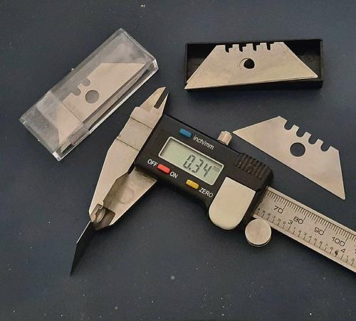
reassemble it, so I assumed that I’d done something wrong. Several failed attempts later I realised that the problem was actually a thin blade. Fortunately as well as many of the knives I also seem to have a few boxes of blades and one from the next box ftted fne. I’ve taken a micrometer to compare the two blades and fnd one pack of blades are 0 44mm or 0 0175” thick The blades from the box that refuse to stay in place are just 0 34mm or 0 0135” thick ‘Ofcial’ Stanley 1992B ‘heavy duty’ blades are 0 65mm or 0 0255” thick
Well, that explains why cheap blade break so easily, with the cheapest being nearly 50% thinner, someone somewhere must be really desperate to fnd a way to save a few pennies on carbon steel Still, I regularly use the ‘bare’ blades for model making and other purposes and they are sharp enough
In the photo, the thinnest blades are those with two notches The others are also third-party and about 33% too thin, but have a third notch which usefully allows you to adjust how far the blade protrudes The moral of this story is obvious…
Neil Wyatt

3 May 2024
Designer: Druck Media Pvt Ltd Publisher: Steve O’Hara By post: Model Engineers’ Workshop, Mortons Media Group, Media Centre, Morton Way, Horncastle, Lincs LN9 6JR Tel: 01507 529589 Fax: 01507 371006
E: Chris@talk-media uk A: Talk Media, The Granary, Downs Court, Yalding Hill, Yalding, Kent ME18 6AL CUSTOMER SERVICES General Queries & Back Issues 01507 529529 Monday-Friday: 8.30-5pm Answerphone 24hr ADVERTISING Group advertising manager: Sue Keily Advertising: Angela Price aprice@mortons co uk Tel: 01507 529411 By Post: Model Engineers’ Workshop advertising, Mortons Media Group, Media Centre, Morton Way, Horncastle, Lincs LN9 6JR PUBLISHING Sales and Distribution Manager: Carl Smith Marketing Manager: Charlotte Park Commercial Director: Nigel Hole Publishing Director: Dan Savage Published by: Mortons Media Group, Media Centre, Morton Way, Horncastle, Lincs LN9 6JR SUBSCRIPTION Full subscription rates (but see page 54 for offer): (12 months 12 issues, inc post and packing) – UK £70 20 Export rates are also available – see page 46 for more details UK subscriptions are zerorated for the purpose of Value Added Tax Enquiries: subscriptions@mortons.co.uk PRINT AND DISTRIBUTIONS Printed by: Acorn Web Offset Ltd., W Yorkshire Distribution by: Seymour Distribution Limited, 2 East Poultry Avenue, London, EC1A 9PT Tel No: 020 7429 4000 EDITORIAL CONTRIBUTIONS Accepted photographs and articles w ll be paid for upon publication Items we cannot use wi l be returned f accompanied by a stamped addressed envelope and recorded del very must clearly state so and enclose suffcient postage In common with practice on other per odica s all material s sent or returned at the contr butors own risk and neither ModelEngineers’Workshop Magazine the editor the staff nor Mortons Media Ltd can be he d responsible for oss or damage howsoever caused The opin ons expressed in MEW are not necessarily those of the ed tor or staff This per odica must not, without the written consent of the publishers frst be ng given be ent sold hired out or otherwise disposed of in a muti ated condition or in any unauthor sed cover by way of trade or annexed to or as part of any pub ication or advertising literary or pictorial matter whatsoever This issue was published on 19 April 2024 The next issue will be on sale 17 May 2024










9 A Sheet Metal Exercise
Dave Fenner took on a lockdown project that put his sheet metal working skills to the test.
12 Setting and Using A Fixed Steady
David George explains how to get the most out of using this essential lathe accessory
15 Getting the most out of your Brushless Mill
ason Ballamy fts a powered table feed to his S 2 brushless motor powered milling machine.
19 Making a Screw Thread Indicator Dial
Paul Tiney makes an aid to screwcutting for his Myford ML4 lathe, over eighty years old and still doing precision work.
27 Micro-Milling
ike Tilby looks at the diferent types of micro milling cutters and how they are used.
32 From the Archives
This month a clever design for cam-locked milling table stops.
33 An A-Z of Metals
ull out and keep the fnal set of pages to fnish your miniature dictionary of terms relating to metals and their properties, from a hobby engineering perspective.

38 A Novel Cutting Oil Delivery System
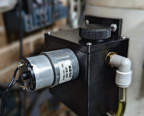
Roger Froud’s cutting oil system was designed for a milling machine but is easily adapted for use on your lathe.
46 Solving Data Corruption In A Digital Scale Readout Display
Fergus Malcolm follows up last month’s discussion by explaining how he implemented his modifcations in practice.
54 Screw Cutting Gauges – A Comparative Review
The Editor discovers some interesting diferences between apparently simple tools.
55 Rebuilding Medway
Queen’s the paddle box fascia


To mark the paddle steamer’s centenary in 2024, Richard Halton takes a look at one of the ‘workshop’ tasks undertaken by the edway Queen Preservation Society’s volunteers.


59 Conditional Statements in Mach 3
A focused article by ohn c hee ofers a way to implement conditional statements for those who write their own machining programmes
64 Beginner’s Workshop
This month Geometer looks at roller chains, still one of the most efcient ways to transfer power
Model Engineers’ Workshop www.model-engineer.co.uk 6 SUBSCRIBE TODAY! GET YOUR FAVOURITE MAGAZINE FOR LESS DELIVERED TO YOUR DOOR! See page 24-25 for details
Contents
£ 8 No339 INSIDE THIS PACKED ISSUE: A SHEET METAL PROJECT Roger Froud combines 3D printing and traditional metalworking. Dave Fenner models an AEC Matador Get more out of your workshop with MEW in the satio ww del-engin .uk CONDITIONAL OPERATIONS IN MACH 3 RESTORATION WORK ON THE MEDWAY QUEEN ADJUSTABLE STOPS FOR YOUR MILLING MACHINE UNDERSTANDING MICRO MILLING CUTTERS SCREW GAUGES COMPARED TACKLING READOUT DATA CORRUPTION ROLLER CHAINS AND SPROCKETS A TO Z OF METALS – FINAL PART HOW TO GET THE MOST OUT OF FIXED STEADIES PLUS ALL YOUR REGULAR FAVOURITES! A CUTTING OIL DELIVERY SYSTEM GETTING THE MOST FROM A BRUSHLESS MILL Jason Ballamy fits a powered table feed to an SX2 Mill. THE MAGAZINE OR HOBB ENG NEERS, MAKERS AND MODELLERS MA 2024 SSUE 339 WWW.MODEL-ENG NEER CO UK A THREAD INDICATOR DIAL Paul Tiney s accessory for s pre-war Myford ML4 IND T DI Tiney’s ML4. 55
Coming up… in our next issue
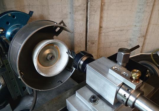
In our next issue Stewart Hart shares his cost and time efcient solution to tool and cutter grinding in the workshop

3 On the Editor ’s Bench
The Editor has a bee in his bonnet over cheap blades
22 On the Wire
The 2024 idlands odel Engineering Exhibition and airbrushing courses.
26 Readers’ Tips
Our winner this month came up with a tip for accurate boring on the lathe Send your tips to meweditor@mortons co uk, you could win a prize
44 Scribe A Line
In this month’s postbag readers react to the content of recent issues We are always keen to hear from you – send an email to meweditor@mortons co uk
65 Readers’ Classifieds
This month’s collection of readers’ for sale and wanted adverts
ON THE COVER
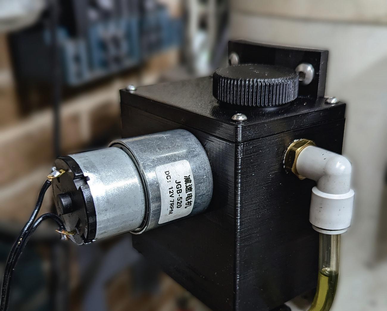
Our cover features the 3Dprinted pump housing for Roger Froud’s automated cutting oil system
See more details on page 38 and download the files from www model-engineer co uk


e will be making the 3 print fles for oger roud’s cutting oil delivery system available for download from the forum at www.model-engineer co.uk 23909 3d-printed-parts-for-rogerfrouds-cutting-oil-delivery-system/ Or search the forum for ‘cutting oil delivery’
Hot topics on the forum include:
Setting up new workshop for clocks. Need advice How to get started in a horology, by bprisk.
Chinese mini lathe bearings Is a bearing change needed and how to measure any play in the spindle, by att T


Proper way to make this part? How to machine a tricky to hold part, by ike Come and have a Chat!
As well as plenty of engineering and hobby related discussion, we are happy for forum members to use it to share advice and support. Come and join us – it’s free to all readers!
7
Regulars
Visit our Website Why not follow us on Twitter? twitter.com/ ModelEngineers hashtag #MEW THIS MONTH’S BONUS CONTENT
Extra Content!
O E EAT ES O S O E E TS O S A B S ASSI IE S E T A S BS IBE A I E S IE S £ No339 INSIDE THIS PACKED ISSUE A SHEET METAL PROJECT TAL PR C Roger Froud combines 3D printing and r ombines traditional metalworking. tradit or D F models AEC Matador Get more out of your workshop with MEW .model-engineer ADJUSTABLE STOPS FOR YOUR MILLING MACHINE. UNDERSTANDING MICRO MILLING CUTTERS. ROLLER CHAINS AND SPROCKETS. A TO Z OF METALS – FINAL PART HOW TO GET THE A CUTTING OIL DELIVERY SYSTEM NG O L DE I Y GETT NG THE MOST FROM A BRUSHLESS MILL Ballamy fits po ed table feed to an SX2 Mill.A THREAD INDICATOR DIAL Paul Tiney’s accessory for s pre-war Myford ML4. T AD INDICA aul Tine s ac or pr M d ML May 2024
www.model-engineer.co.uk




















A Sheet Metal Exercise
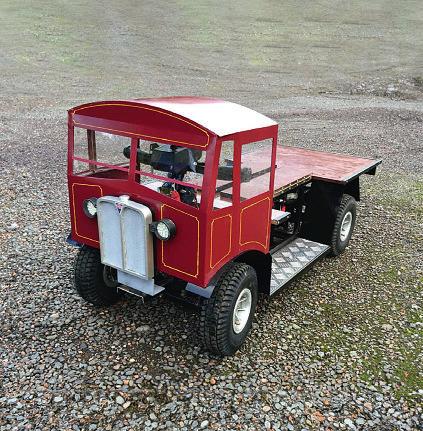
Dave Fenner built a model AEC Matador as a lock down project that involved some interesting sheet metal work.
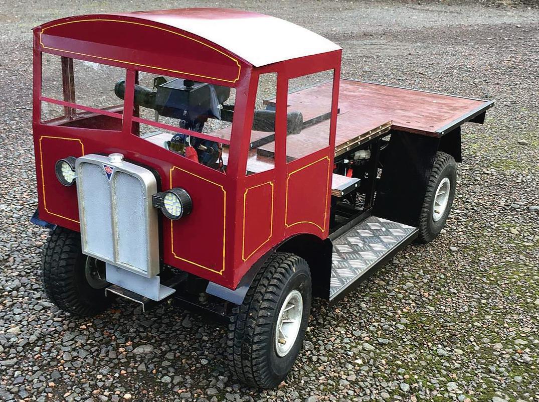
Those of us who were retired pensioners were spared the much of the fnancial hit experienced by many during lockdown. It did though impose severe constraints on the usual social activities As a result there was more time to retire to the workshop As the grandchildren were getting beyond the toddler stage it seemed ftting that one project might be aimed at amusing them It is said that the sincerest form of attery is imitation, and in this case, it was prompted by seeing an advert by Ian’s Electric Engines”, IEE) where the advertiser ofered a set of body parts to convert a mobility scooter
into one of two lorry models, roughly uarter scale The frst was a Sentinel steam waggon, and the second an AE atador. The atador was generally composed of attish panels more suited to the facilities in my workshop I therefore opted to produce my own interpretation of that prototype, p oto It should be noted that this article is being written sometime afer a house move which forced a severe downsi e of workshop space and facilities arious items of kit employed at the time were sold of and there is a degree of reliance on photos taken at the time of build.
Scouring the umtree ads for a mobility scooter led to the purchase of a ymco ini S, which on detailed examination proved a bit too good to cannibalise and a bit too small for the project It was sold on The IEE website does specify a particular make and model, the Shoprider Sovereign, so the ads were studied again, and one of these, in uestionable condition, did eventually turn up about 40 miles away
Initial Testing and Modification
The bodywork and seat were removed, and a couple of old car batteries
› 9 Sheet Metal Project May 2024
1
The Finished Truck
connected in series to give the required 24 volt power The thing refused to go ortunately it was a repeat of a fault found earlier on the ymco any mobility scooters have a spring loaded multi disc safety brake which is built on to the motor hen power is applied, the integral solenoid should pull back the spring pressure and release the brake.
owever if the thing is lef unused for a period of time, especially in an

unheated shed, then mild corrosion sets in and locks the brake The remedy is to dismantle and clean the multiple discs, using clamps to control the release of the internal spring pressure. Once the brake was freed of, the scooter behaved as expected
One aspect of the chassis geometry which became evident was that the front track was about two inches narrower than the rear I suspect this is to improve manoeuvrability in confned spaces. To improve the appearance of the model, a new front axle beam was constructed from 25 x 25 x 3mm E s uare steel tube making the front and rear track e ual. The steering column was shortened, as were the handlebars,

these changes being made at a later stage, once the cab si e and position were determined
Bodywork Design
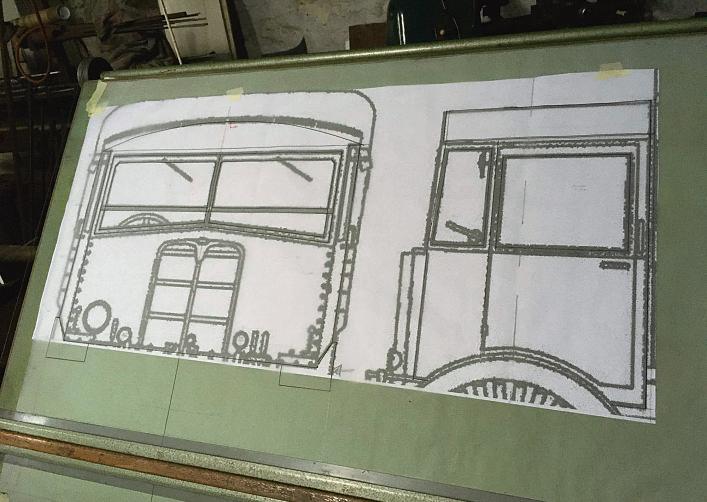
Although in an earlier life I did spend some time in a drawing ofce, I am certainly no artist, so looked on the internet for suitable outline drawings of the cab These were then printed out at pretty small scale on A4 paper. It was then a case of working out a magnifcation ratio to suit the track width and wheel diameter The A4 was then taken to our local print shop who produced the larger scale output which could be fxed to the drawing board as in photo 2, and used to trace of the various sheet metal parts from 1 g or 1 2mm steel sheet
Model Engineers’ Workshop www.model-engineer.co.uk 10
Full size print on drawing board
Rotary bench shear(extension handle stored in base)
Monodex cutter showing wide kerf and rolled swarf
2 3 4 5
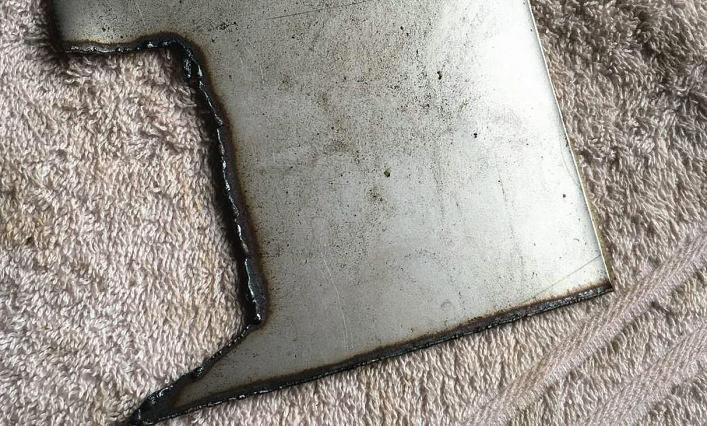
Typicaledges cut withplasma cutter

Methods for Cutting Sheet Metal Parts in the Home workshop
Over some forty years or so I had accumulated a reasonable array of tools and disposed of some) for sheet metal cutting Each has its own advantages and drawbacks
• Treadle guillotine this would have been ideal for cutting straight lines, pretty uiet and no dust or swarf, nfortunately it had been sold some years earlier
• otary bench shear, photo 3, again good for straight lines but does cause curling plus edge distortion plus knurl” type marking on one side of the cut
• Tinsnips can be hard work on the hands and cause problems similar to the rotary shear but minus the knurl efect.
• onodex cutter can be hard work but gives little distortion, photo 3 There was also a pneumatic tool with similar cutting geometry which even for 1 g material proved underpowered In either case a central curled slice is sheared away as swarf between the two cuts It can be used for curves.
• Angle rinder ftted with a 1mm cutting disc will cut accurate straight lines, fairly uickly but with signifcant noise and dust.
• ibbler- my nibbler was a pneumatic version which I found underpowered and prone to stalling even on 1 g material. The type which attaches to an electric drill might be more powerful The cut is near distortion free, but it’s a noisy process. The swarf is produced as small sharp
crescent shaped pieces, so it is well worth cleaning up carefully aferwards. Again curved cuts are posssible.
• Body Saw ip Saw) this was a gadget acquired for cutting away car panels In that application it is an efective tool or cutting on the at it could probably be used with a guide bar, but not tried by me airly noisy, with high fre uency vibration The swarf comes of as sawdust There are special blades for these, but it is possible to modify a broken fne tooth hacksaw blade for reuse As it is a sawing action, the distortion is negligible
• ig Saw this is basically a similar process to the ip saw, but as the speed is lower, the noise is of a lower fre uency Again, a fne-tooth blade is needed
• lasma utter I tend to think of this as the modern version of the oxyacetylene cutting torch It does though re uire a compressor The cut edge is melted and oxidised, but by using a guide bar, fairly accurate cuts can be achieved, as may be seen in p oto , and very uickly A light run over with an angle grinder will remove the melted oxidised slag eneral distortion is negligible
• Bandsaw I still have my Taiwanese 4 inch hori ontal vertical bandsaw purchased around 19 0 It is fre uently called upon to cut sheet material but normally has a blade of either 14tpi or 1 tpi I always remember articles in E by the late Bob oader where he recommended that for thin materials a blade with at least three teeth in contact was ideal owever, cutting thin steel on the bandsaw does work very well It is accurate, controllable, distortion free, with low vibration as the cutting force is constantly downwards The downside is that due to the coarseness of the blades, eventually a tooth will break, followed by its neighbour. ou then fnd yourself timing when to apply cutting pressure and when to release, in an attempt to avoid the missing teeth
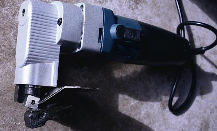
• Electric shears These, photo 6, were purchased afer this project so were not available to use at that time. Subse uent testing showed that it was possible to cut with reasonable accuracy and that the amount of distortion was rather less than with the roller shears. Photograph 7 shows a sample, as cut.
› 11 Sheet Metal Project May 2024
Electric shears
6 7
Sample cut using electric shears

Distortion Problems
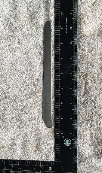
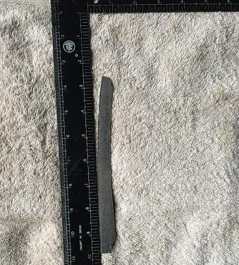
The bodywork re uired a number of angle pieces measuring about 10 x 10 x 1 2mm section These would be folded in a home brew 24-inch folder so re uired strips to be cut approximately 20mm wide. The angle strips would ultimately be spot or mig welded to the inside of the cab, and at least one side would be hidden Even though the roller shears produced signifcant distortion, I did still choose this method on the grounds of simplicity, cleanliness and silence The cut strips had a pronounced curl which was taken out in the vice and then the ypress, The part was then at but displayed a pronounced curve as could be seen in photo 8. Another piece of kit acquired years ago for car restoration work was the shrinker stretcher, p oto and it was used to bring the strips to reasonable straightness as may be seen in p oto . or readers who have not encountered these tools, they are supplied with two sets of dies, and the action either stretches or shrinks the edge of the material. The purchase was originally prompted by need to produce lengths of curved angle for locations like boot lid apertures or wheel arch edges
Cab and Body Construction
The various components were either spot or mig welded, the choice being fre uently dictated by access considerations. A sub chassis was designed to allow the two batteries to be ftted along the centre line, so that the at bed could be hinged up
This would then allow clearance for legs and for feet to rest on the foot boards. The material chosen for the chassis was 3 4inch x 1 gauge E tube, principally because I had some on the shelf The at bed was cut from 9mm plywood, edged with plastic trim, the hinged parts being ftted with piano hinges ab windows were cut from 2mm perspex held in place with silicone sealer.
Lights
or the rear lights, the originals were reused, ftted with 12 volt E bulbs wired in series or the front, a search on ebay came up with round E arrays of about the right si e, so two were purchased ousings were then 3 printed to accommodate and locate these
Radiator
Afer fnding the correct shape on the web, this was traced then copied on to pieces of , and cut out The AE badge was also found on line and printed out at suitable si e. Aluminium mesh formed the two grilles It was a turning job to produce a reasonable looking radiator cap from a short length of aluminium bar.
Painting and Lining
A uick check through the tins of paint lef over from years of car repair yielded one of auxhall maroon which dated back to a ova in the late 0’s Afer a coat of grey primer, this was sprayed on to the cab assembly Black was chosen
9
10
for the chassis and lower details ere it was applied by brush or the lining, I still had a tin of signwriting yellow ac uired some years before, and this was applied somewhat cack handedly with a drafing bow pen The heading photo shows the result
Batteries
A pair of new budget mobility batteries were sourced from Tayna batteries, these being the cheapest I could fnd at the time I have no connection with Tayna but am happy to report that the batteries continue to perform well afer some three years or so of regular us
Model Engineers’ Workshop www.model-engineer.co.uk 12
still a pronounced curve
in use to straighten a narrow strip Strip aferstraightening
Aferplanishing,
Shrinker/Stretcher
Setting And Using A Fixed Steady
David George explains the use of this essential aid for supporting long workpieces in the lathe.
Using and setting a fxed steady is fairly simple but here are some ideas and uses that are particularly useful
The main use is to hold and support a long shaf or tube whilst turning, drilling or parting of to length The frst thing to do is ft the steady to the bed looking at the location faces and checking for swarf
and damage to both the steady and the bedways I give the mating faces rub with a small smooth stone and afer giving a wipe with a clean paper wipe followed by a lite oil smear as it is likely that it will be slid along the bed at sometime during use The other thing is to check that the steady clamps in the correct places, for example on my type lathe the front
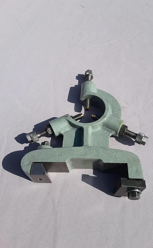
wedge clamp pulls it down and across to locate on the back of the rear of the bed and the rear clamp pulls the steady down and clamps it down as well On other lathes it is more usual to locate the steady on the pyramid form on the top of the bed with a single clamp under the bed with a bolt through the bed casting slots, photos 1 and 2.
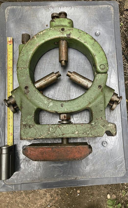
› 13 Fixed Steady May 2024
t pe edstead
1
arrison edstead
2
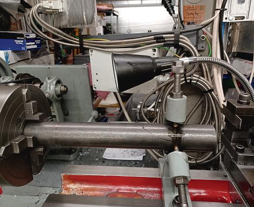
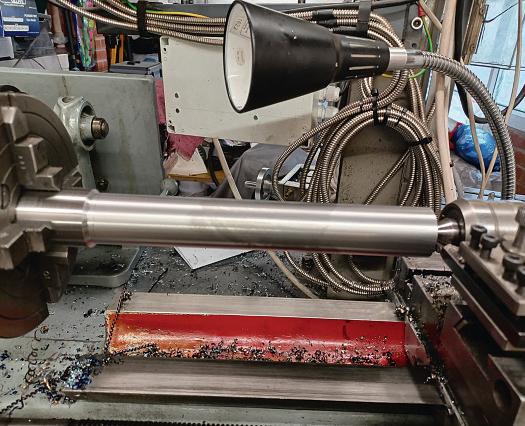
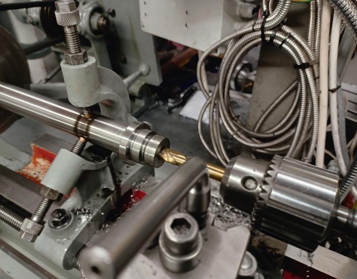
If you put a short setting piece into the chuck which makes it easier to set the fngers to the correct diameter or turn a piece of the work, if possible, to the correct si e ut the steady on to bed and slide it with the fngers clear of the setting piece, slide it along and clamp it down along the setting piece length and clamp down to the bed Then adjust the support fngers till they just touch lightly one at a time, run the lathe at a medium speed feeling the pressure on each of the three fngers till you get an even pressure on all three and with some oil on the diameter there is no excessive heat build-up. ou
should then stop the lathe and release the top fnger to allow the steady to be moved to the length that you need for the long piece. Afer moving the steady to the correct place along the bed replace the setting piece with the job in hand, tighten down the top fnger lightly to the job, turn the chuck by hand feeling for tight spots or excessive friction and oil with a bed way oil Turn on the lathe and tighten the fnger slightly feeling the bar for excessive heat increase caused by overtightening then if it gets slightly warm that is all right but check regularly for heat increase especially if the turning or

drilling operation is causing the metal to warm up and expand as well ou can release the top fnger slightly at any time if excessive heat build-up occurs, and stop and cool if necessary, always keep lubricating it regularly!
hen I have a piece of black bar or non-concentric bar to turn, I hold it in the steady as tight as I can which may be a bit loose as it may not be exactly round. I then centre drill the end and support the bar with a revolving centre which allows me to turn a band width on the black bar to set to and use as the area for the steady to run on properly, photos 3 and 4
Photographs 5 and 6 show some examples of other operations using the steady for support.
Model Engineers’ Workshop www.model-engineer.co.uk 14
holding lac ar
drillingthrough solid ar
scre cutting location thread
3 4 5 6
s i ed lac aron centre
Getting the most out of your Brushless Mill. Part 1
Jason Ballamy follows up his series on Milling for Beginners (MEW 261 and subsequent odd numbered issues to MEW 279) with a series of linked articles focused on using brushless hobby mills.

What’s included in thepackage
Over the next few articles, I will be looking at how to get the best out of brushless hobby mills particularly in regard to speeds and feeds. Several recent threads on Model Engineer Forum have prompted this as some of the more traditional approaches which are ofen based on using belt/gear driven more rigid machines don’t always work so well when applied to the smaller bench top hobby type mills To help demonstrate the optimum feed rates I was sent a power feed unit from ARC Euro Trade to ft to the SIE S 2 that featured in the “milling for Beginners” Series and I will cover ftting that frst.
Power feed for the SX2.7 Mill
I have had a similar power feed to this one ftted to my SIE 3 for just over seven years which was sent to me by ARC to evaluate when they were originally considering stocking this item However some recent threads on ME forum related to feed rates when cutting with shell face mills prompted ftting a unit to the S 2 mill with a standard table that I also have in the workshop
As usual a large sturdy box arrived next day from ARC Euro Trade and inside that along with some shredded cardboard packaging was a slightly smaller box containing all the necessary parts which were
individually bagged and held within rigid foam dividers
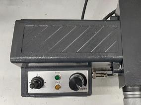
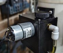
Photograph 1 Shows the contents of the package starting in the top middle an working anti-clockwise we have: The main feed unit with variable speed knob, lef right toggle switch and two LEDs to indicate power and fault. A 240 A to 24 transformer. Power lead for the transformer ftted with 3 pin plug top A small enclosure with the limit switches and attached lead. Two adjustable limit stops. Selection of socket head screws needed to attach the feed to the mill. The fnal item is the clutch adaptor block which varies according to which
› 15 Brushless Mill May 2024
1
mill/table combination the package is intended to ft, so make sure you order the correct one for your particular machine. The instruction booklet covers ftting the unit to the various mills within the SIE range.
Fitting
Before commencing ftment of the power feed, it is a good idea to check that the gib strips are correctly adjusted particularly checking that there is no decrease in ease of movement at the
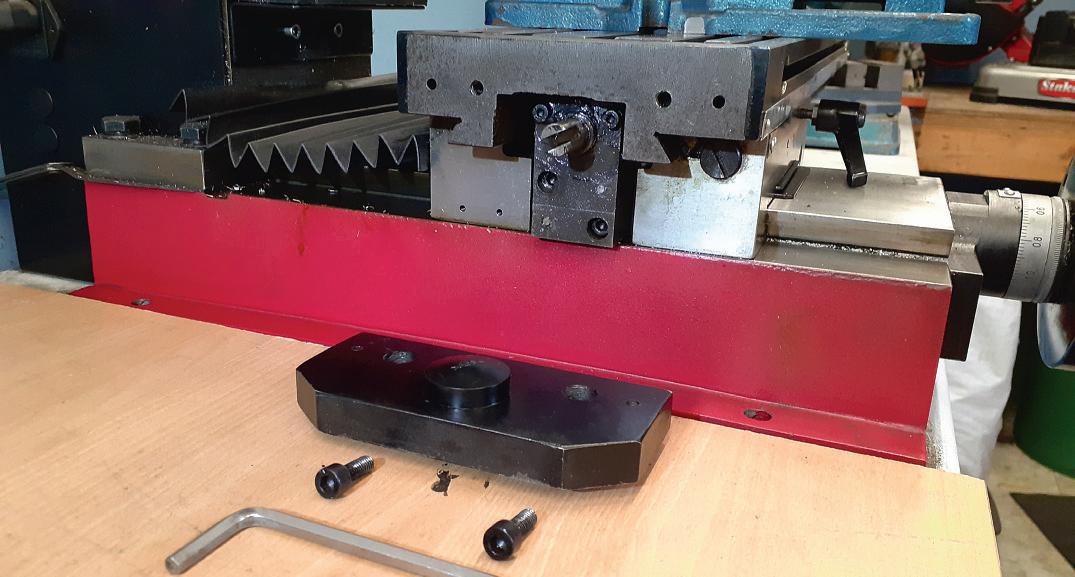
two extremes of travel and to lubricate the ways and lead screw Then move the table to a position just short of its maximum to the right which gets the nut close to the end of the lead screw. The frst thing to do is to remove the existing end plate from the lefhand end of the table by unscrewing the two M6 socket head screws and then gently ease the plate away from the table. There are two location dowels that may make it a bit stif to remove but mine came of uite easily,
photograph 2. It’s also worth noting that with the end plate removed access to the two backlash adjusting screws at the top of the lead screw nut is a lot easier so they can also be adjusted now if they need it.
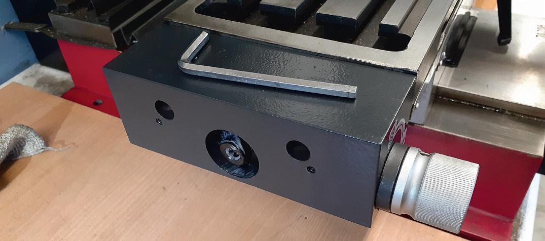
The clutch/adaptor block can now be screwed into place using the two longer M6 Socket head screws provided. Take care to ensure that the slot in the end of the lead screw lines up correctly with the mating male part in the clutch, you may need to turn the axis hand
Model Engineers’ Workshop www.model-engineer.co.uk 16
2 3
Existing endplate removed
lutch loc tted

wheel back and forth as the screws draw the block into place to get the correct engagement Before fully tightening the screws check that the hand wheel turns with a similar efort to when you started and that the block is not pulling the end of the lead screw out of line, photo 3.
The S 2 already comes with two 3 tapped holes in the front of the table
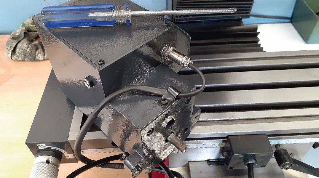
which makes for easy no drill mounting of the limit switch box using the provided screws through the backing plate that protrudes below the bottom of the box. The two adjustable stops can also be ftted to the table’s front tee slot and nipped up I fnd most of the time they can be lef at the ends of the slot simply as a safety feature if you
forget to stop the feed but can also be positioned as re uired when wanting to stop the table in preset positions, photo 4
Before mounting the actual feed unit connect the limit switch wire into it’s socket and make sure the wire is secure through the “P” clip strain relief, p oto . I also found that the two
› 17 Brushless Mill May 2024
4 5 i it s
itch and actuators tted
Strain reliefclip around cable

tapped holes in the clutch/adaptor block had some paint in them so uickly cleaned out the threads with an 4 tap, photo 6
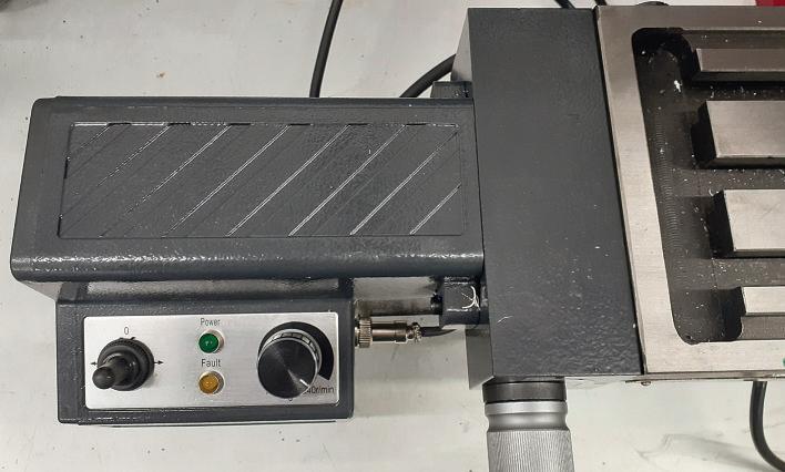
The completed installation can be seen in photo 7 The green LED indicates when there is power to the unit and the amber one when there is a fault. The fault light will tend to come on if the mains power is turned on when the speed control knob is in any position other than of, so acts as a safety feature preventing the table moving afer a power cut or just unintentionally when frst powered up It is easily cleared by turning the speed control knob to the of position fully anti-clockwise until it clicks) and then you are ready to go
To engage the feed the clutch knob is turned 90 degrees clockwise so
that the arrow is horizontal, you will probably have to turn the x-axis hand wheel a little at the same time to get the two halves of the dog clutch to line up and fully engage. The speed knob can then be turned to the re uired position and the toggle switch icked lef or right depending on the direction you want the table to move. The knob needs to be turned to approximately the 10 o’clock position before the gear head motor overcomes any stiction and the table begins to move. The slowest rate therefore works out at approximately 5mm min round to the fastest of approximately 450mm min. See link to video at the end of this article To return to manual feed simply turn the clutch knob anticlockwise until the arrow is vertical In use it is still possible to use the hand wheel while
the unit is engaged but as there is a lot more resistance due to having to turn the motor as well it is best just used for small movements such as when toughing of to establish height or locate an edge rather than hand feeding a cut
If the stops are to be used then they can be placed roughly where re uired by loosening the M8 nut at the front, sliding into place an tightening the nut again ine adjustment is then possible by altering the length of the sprung adjusters ote that depending on the speed of travel there will be some compression of the stop adjuster and switch plunger before the unit switches of See second video in link
Summary
The power feed unit was very easy to ft and if my other one is anything to go buy should give many years of trouble-free use. Although not something you must have or even need to use all the time once ftted, the Power feed does enable the use of higher feed rates for insert tools than it is possible to turn the hand wheel at as well as slow and steady feeds needed for things like traditional SS y cutters both of which result in better fnishes Or it can simply be used as a fast traverse to return a tool to the start of a cut or when clocking in long work pieces.
A small safety note, when using the power feed, it is good practice to disengage the -axis hand wheel so that it does not spin round wildly and hit you, it also reduces vibration that can afect the fnish of the work piece In the videos that accompany this and the following articles I have removed the spring so the handle stays engaged as it gives a simple visual indication of how fast the hand wheel is rotating
References
Power Feed https://www arceurotrade co uk/Catalogue/Machines-Accessories/ illing- achines SIE -S 2 - ill S 2ill-Accessories owerfeed-for-SIE2 -and-S 2 - ills
ideo https www model-engineer co uk 9 59 power-feed-for-the-siegsx2- -mill
Model Engineers’ Workshop www.model-engineer.co.uk 18
6
Removing paint from threaded holes Installation Complete
Making a Screw akin Thread Indicator Dial o
Paul Tiney made this aid to screwcutting for his long in the tooth Myford ML4.
Wh en it comes to screw cutting, I revert to my second lathe, (swank!) an elderly Myford ML4 A venerable old prewar machine found at a car boot sale, complete with change wheels, for £30 Before you whisper “lucky blighter” it was some years ago when “the pound in your pocket etc ”
One of the most important aspects of screw cutting is making sure you “pick up” at the same spot every time you take a cut There are all sorts of mathematical calculations you can make concerning the T.P.I. of your lead screw, the T.P.I. of the thread being cut, and talk of chalk marks, and hand reversing without disengaging; some, or all, of which I have
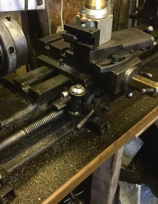
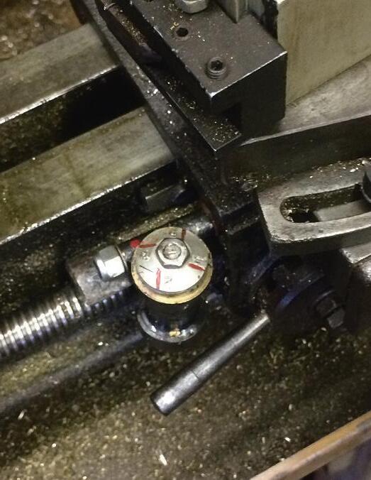
tried However for real peace of mind a “thread indicator dial” is the answer One attached to the carriage that can be swung into and out of mesh with the lead screw as required Once available as an “extra equipment option” for most lathes but now only an expensive “vintage part” for mine Therefore if I wanted one, I was going to have to make it, and so, as they say, “the die was cast”, p otos and 2. There are plenty of pictures of them in books, so overall design of the thing was very easily arrived at
The frst and most obvious problem was to obtain a gear wheel that would engage with the lead screw This is a sort of skew gear of almost helical form
having the same pitch and form as the lead screw; in the case of my wee Myford an 8 tpi acme thread With no gear cutting available a compromise was going to have to be arrived at, purists should look away now I decided that an ordinary straight cut gear would do the job Although it wouldn’t engage and mesh completely it should be fne as it wasn’t going to be transmitting any large drive loads When the clasp nut on the carriage is not engaged with the lead screw the dial simply revolves, driven round by the lead screw When the clasp nut is engaged the movement of the carriage along the lathe bed cancels out the rotation of the dial and it no longer revolves The only load on
› 19 Thread Indicator Dial May 2024
1 2
Fitted to carriage.
Driver's view

Closeup of components.
the gear is that required to overcome the friction in the body of the indicator, a tri ing amount
A gear only having 8 teeth and a circumference of 1 inch was out of the question so a 16-tooth wheel with a 2
inch circumference was settled on Of the shelf gears are mostly metric sized and of metric profles, ofen made in China, as you would expect, and are readily available online Fortunately the purveyors of these gear wheels also publish fully dimensioned specifcation charts and drawings in their adverts
Afer much deliberation and school boy geometrical calculations I placed an order for a couple of gears of 16 tooth, No1 Modulus, 18mm diameter Oh, and they were ridiculously cheap
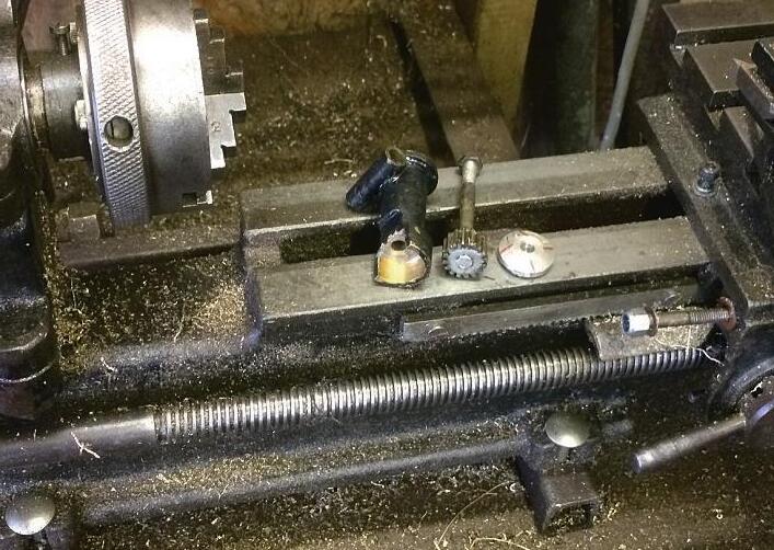
Once they had arrived and I had satisfed myself that they would do the job I got on with making the other parts, photo 3
The main body was turned in brass to a satisfying profle and bored for the drive spindle The bottom was drilled, and a boring bar used to open a hole large enough and deep enough to accommodate the gear wheel Removing it from the lathe this lower portion had half of it cut away with a hacksaw to allow the gear to engage with the lead screw, photo 4
The drive spindle was cleaned with emery and soldered into the drive gear Soldering seems to have gone out of fashion and has now been replaced by the use of “super glues” By placing the parts to be soldered on the hot plate of my Rayburn they warm up nicely as I make my porridge in the morning I like to use “killed spirits” (zinc dissolved in hydrochloric acid) ux for most soldering jobs except electrical and plumbing work, and if you do the same do remember to wash it all of in water aferwards oes anyone else remember the funny Fry’s Fluxite Solder Imps, photo 5, from the old magazine adverts? Sorry I digress, to continue
The other end of the spindle had a thread cut on it ready to receive the dial The dial was turned to shape from a piece of alloy and drilled and tapped to suit the spindle thread A small portion surrounding the central tapped hole was lef raised on the back of the dial to provide running clearance It was marked using a sharp pointed tool held in the tool holder and the stop and headstock gear wheel used to index it
A short length of brass bored and fled on the side to the profle of the main body was soldered in place for the mounting A lock nut placed above the
Model Engineers’ Workshop www.model-engineer.co.uk 20
3 Parts.
4


