Talk Media, TheGranary,Downs Court, Yalding Hill, Yalding,Kent ME18 6AL
PUBLISHING
Sales &Distribution Manager: Carl Smith
Head of Marketing: Charlote Park
Commercial Director: Nigel Hole
Publishing Director: Dan Savage
Published by: Mortons Media Group,Media Centre, MortonWay,Horncastle, LincsLN9 6JR
SUBSCRIPTIONS
Full subscription rates(see inside forofers): 12 months, 12 issues, inc. post &packing- UK £71.40. Export ratesare also available, see www.classicmagazines.co.ukfor moredetails. UK subscriptions arezero-rated forthe purpose of Value Added Tax.
Enquiries: subscriptions@mortons.co.uk
PRINT ANDDISTRIBUTION
Printedby: Acorn WebOfsetLtd, WYorkshire. Distribution by: Seymour Distribution Limited, 2East Poultry Avenue, London, EC1A 9PT Telephone: 020 7429 4000
EDITORIAL CONTRIBUTIONS
Acceptedphotographs and articles will be paid forupon publication. Items we cannot use will be returned if accompanied by astamped addressed envelope, and recordeddelivery must clearlystatesoand enclose suficientpostage. In common with practice in other periodicals, allmaterialissent or returned at the contributor’sown risk, and neither Model Engineer &Workshop Magazine, theeditor, the staf,nor Mortons Media Group Ltd can be held responsible forloss or damage, howsoevercaused.
Theopinions expressed in ME&W arenot necessarily those of the editor or staf
This periodical must not, without the writen consentofthe publishers, be given, lent,resold, hired out, or otherwise disposed of in amutilated condition or in anyunauthorizedcover, by wayoftrade, or annexedtooraspart of any publication or advertising,literary or pictorial mater whatsoever.
This issue waspublished on: 21 February 2025
The next issue will be on sale: 21 March 2025
Editor
Welcometothe first magazineunder thetitle Model Engineer &Workshop
Strictly this is thelatest of manyiterations of Model Engineer,soit continuesthe numbering andvolumes of that title. Nonetheless, it’s important to stress that thenew magazine is intended to be abalanced combinationof Model Engineer and Model Engineers’ Workshop.A true re-uniting of thetwo titles, notone becoming an annextothe other.
It wasagreat privilegetoedit MEW fornearly eleven years, andIlook forwardtothe futurefor ME&W.I’d like to thank Martin Evans, who’s done a wonderfuljob of editing ModelEngineer in recent years, forgiving me so much help andassistance withthe handover Thanks also to Diane Carney,who has always been agreat sourceofhelpand inspiration from my earlydays, when she wasfulltime editor of ME,through to nowwhen shewill be continuing as DeputyEditor of ME&W
Iknowmanyreaders will be nervous about whatthe futureofthismagazine
Editor
might look like; amagazine that has been literally synonymous with the greathobby of model engineering for over125 years. We have sixteen extra pagesand we will be working hard to make sure thereisthe variety to keep allreaders happy. Ihopethis will assuagethe concerns of those readers of either title who might see this wider ranging magazine covering topics with which they areless familiar
Ourfirst fewissues will be asetling in period so we maymakesome more changes. We will soonbeencouraging allreaders to take part in asurvey on whatyou want to see in the magazine. With theexperienceofour first fewissues andyour feedback,Diane andI aredetermined that Model Engineer &Workshop will continue to be thebest read forall hobbyand model engineers
Neil Wyat
Neil Wyat
Diane Carney Deputy
Contents
9 ASpring Parting Tool
This accessory,designed by Bruce Porteous, is atested solutionfor reliable partingofonlargerlathes.
15 The BR Standard 2-6-0 Class 4StandardEngine
This instalment from Doug Hewson,one of the leadingdesignersofclose-scale model locomotives, includes some useful tips.
Paul Zeusche details techniques for polyurethane casting and mould makingin thistwo-part article.
26 AGear Depthing Tool
This scissor-style tool by Tony Birdhelps ensure accuratemeshing of gears.
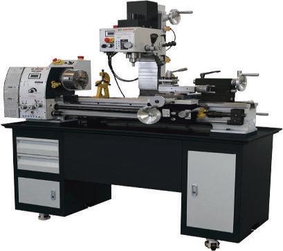
34 Working on the Lathe: Drilling and Boring
Useful advice forbeginnersand the more experienced hobbyengineer from Neil Raine.
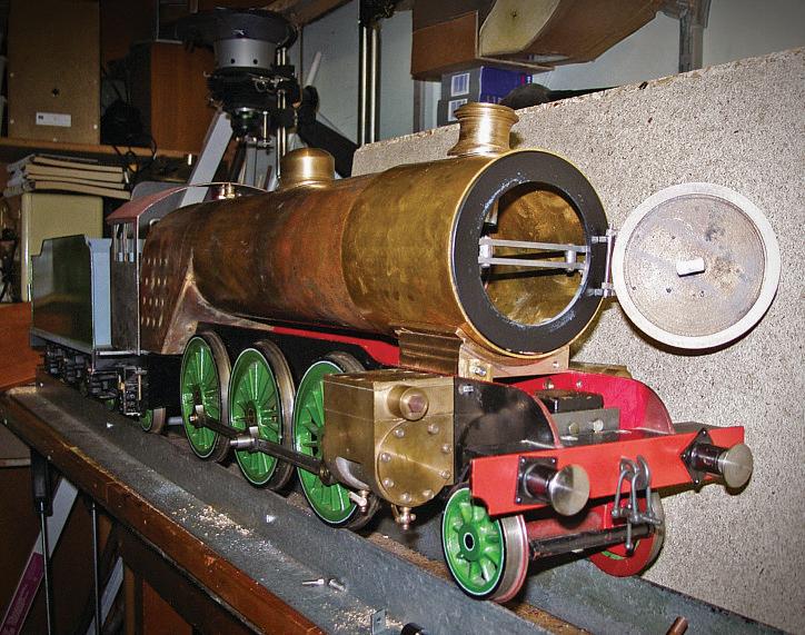
38 COVER STORY: How, Not, to Build aLocomotive… forSomeone Else
John Woods and JonathanBregazzi, on oppositesides of the world, onthe building of aManx Railway 2-4-0 tank locomotive.
44 The Stationary Steam Engine RonFitzgerald tells the story of the development of the stationary steam engine with abriefdiversionabout the earliest steam locomotives
46 Harold Hall (1933-2024)
We mark the passingofModel Engineers’ Workshop’s second editorwith his perspectiveonthe magazine and the hobby.
51 UsingComsol with aSteam Boiler
Manyreaders maybeunfamiliarwith high meltingpoint conventionalsolders David Wainwright explains howheused onetocompleteanelderlyboiler and getitcertified
56 X1 Mill Belt DriveUpgrade
John McPheecompleteda particularly neat spindle upgrade using 3D printedparts.
60 Beginner’sWorkshop
Removing broken taps anddrills is aproblemweall face from time to time. Geometer passesonhis workshopwisdom.
62 AWorkshopDiary Ordinary superglues ofer away to address arange of latheworkholding challenges; AlexduPre shares his approach.
65 ATandemCompound MillEngine
David Thomas makesaHartnell Governor forArnoldThrop’s classic Corliss-valved engine.
76 Upgrading aLathe CrossSlide
David George makes anew cross slide leadscrew forhis venerable M-Type lathe, andimprovesits action along the way.
Regulars Visitour Website
3 SmokeRings
Theeditors welcome youtothe first issue under the masthead of Model Engineer &Workshop
42 Postbag
Afull postbagthis month, with your comments, questions and ideas. Send the editors your leters at meweditor@ mortons.co.uk.
50 Readers’Tips
This month our winner is atip fora simple tailstock veeclamp.Send your tips to meweditor@mortons.co.uk- you could win aprize.
69 Club Diary
Whynot expand your hobbyhorizons by going along to meetfellowmodel engineersatone of these meetings?
70 Club News
GeofTheasby shares his regular round up of what’sbeen happening at the clubs.
74 On the Wire News of this year’sMidlands Model Engineering Exhibition, and howtoget your owndesigns 3D printed in metal.
80 Readers’Classifieds
Our monthly selection of readersfree advertisements. Is it time foryou to grab abargain?
Your magazine is growing and changing into Model Engineer &Workshop.Find out more and letusknowwhatyou wouldliketosee in the new, larger magazine at: www.model-engineer.co.uk/forums
Visit theforum to find the files forcarryingout JohnMcPhee’s X1 spindle upgrade on your ownmachine.
Hottopics on the forum include:
•MyfordTopslide base casting graduations started by Martin Kyte -They seem to be unique to each machine!
•Question about correcting error introduced by using straightslide in valvegear started by Chris Kaminski. -Figuring out diferencesinvalvegear designs
•WhatDid YouDoToday2025 started by JasonB -Our regular thread where Forum membersreport back on their adventures.
•Had Another Go started by Nigel Graham 2- Asimple questions turns into an extended discussion on using AlibreAtom3D
Comeand have aChat!
As well as plenty of engineering and hobbyrelateddiscussion, we arehappyfor forum memberstouse it to shareadvice and support. Come and join us –it’s free to all readers!
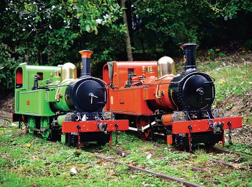
On theCover Next Issue
Our coverfeatures John Wood’sand Jonathan Bregazzi’s matching ‘Manx Peacock’ locomotives, symbolising the reunification of ME and MEW. Moredetails on page38.
In our next issue RodJenkins looksatthe time honoured techniques formilling in the lathe. Whynot followusonX? www.x.com/ModelEngineers hashtag
ASpringParting Of Toolholder
Bruce Porteous describes aspringparting tool forthe DB10 andother largerlathes.
Parting of is somethingI’ve alwaysapproachedwith a degree of careand some trepidation.Usuallyitgoes fairly smoothly but when it does go wrong it can be 'interesting'.This
article describesa springparting-of toolholder made formyChester DB10 lathe that makesparting amore reliableprocess.
Whilst I’ma charteredengineer, that’s duetoacareer in sofware. My first
sofwarejob though wasinacompany that made metrology equipment. One lessonwas that everything is flexible -for aturned part,wecouldtell how many jaws thechuck that held the part had. Themetal is squeezed by the chuck, turnedround butthen springs back slightly whenthe part is takenout of thechucksoends up with three or four lobes,albeit to atinyextent. This leads directly to parting of -if youconsider thecross-slide and toolpost as being flexible, what happens if youput adownwardforce on the tool? Becauseofthe overhang and flexibilityittendstomoveforward and take adeeper cut- whichincreases the downward forceand so on.Onagood daythatsorts itself out, on abad day thetool digsinand there’saloud bang as something gives. This is generally abad thing with aruined part or half a parting-ofblade whistlingpast your ear Thecommon solution is to use a rear tool-post. With that geometrythe upward forceofcuting tendstopush thetool away from thepartsothat the process is self-adjusting.Having built one formyChester DB10 lathe Ican confirmthatthisworks fine and that it’s
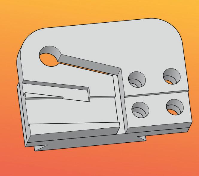
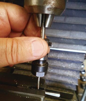
Photo 1: 3D printed prototype.
possible to easily part of largerdiameters and at higher speeds than with the tool in the normal fronttoolpost. The one snag though is the rear toolpost tends to getinthe wayofother operationssoonly gets broughtout whenit’s really needed.
THESPRING TOOLHOLDER
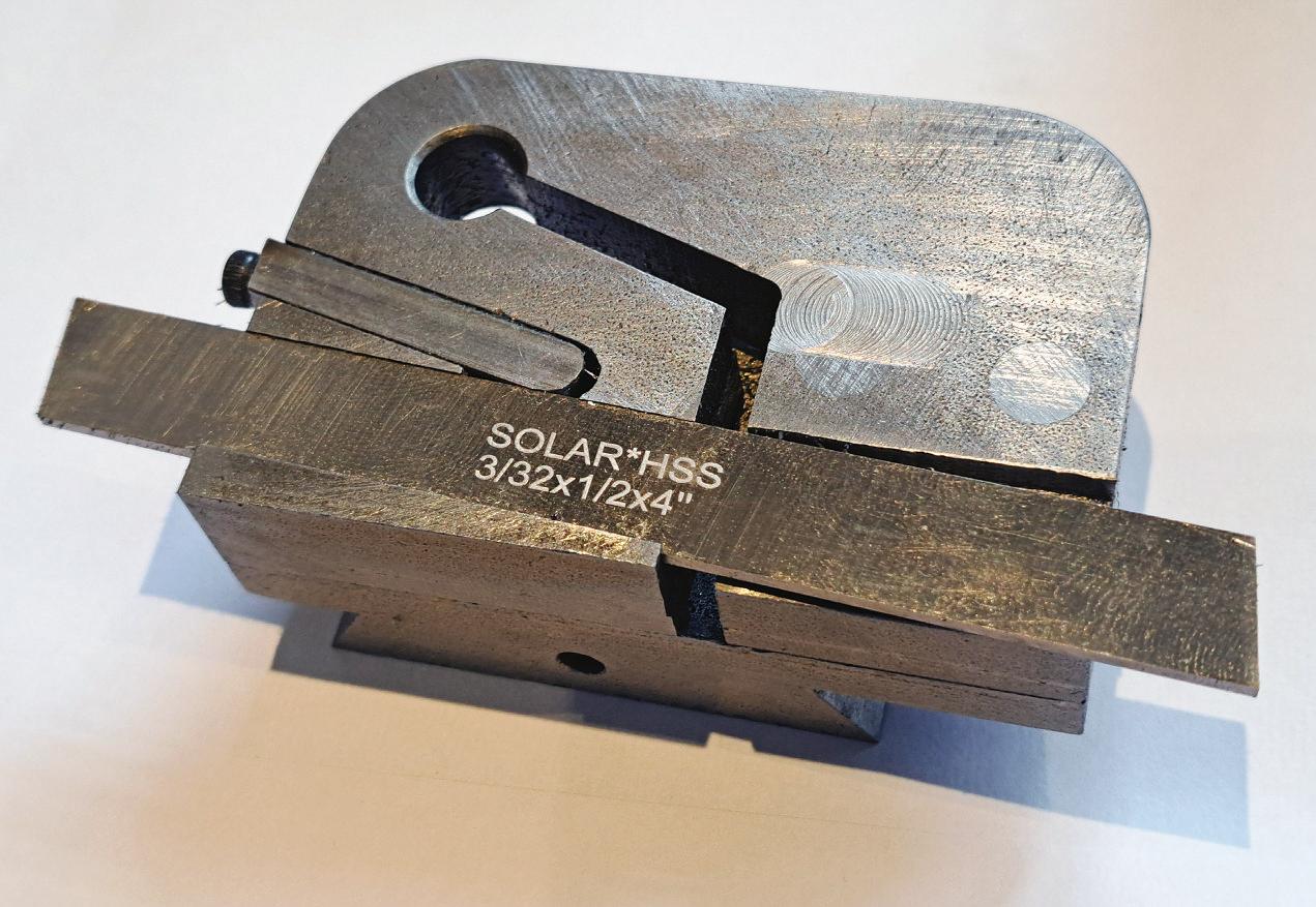
Theidea hereistocreatethe geometry of the toolholder so that under downward pressure it movesawayfrom the part rather than digging in. Starting with astandardcommercial ½x 3/32” parting-of blade, afew sketches came up with some ideas. Thepartingof blade is held underneatha 'spring'. The 'spring' hereisstill fairly substantial as it only needstomovefractionally underload. I’dliketoclaim complex stress calculations to getthe spring dimensions correct butinreality,itwas moreofa TLAR (that looksabout right) designprocess.
Theother aim wastoget it to drop
directlyintomy(Hemingway kits)quick changetoolpost (QCTP). Afer afew sketches on paperI used FreeCAD to come up with the3Dmodel in fig. 1 that Icould 3D print to check forsize, oddities (like holes breaking through) andsee if Iwas happywith the dimensions.
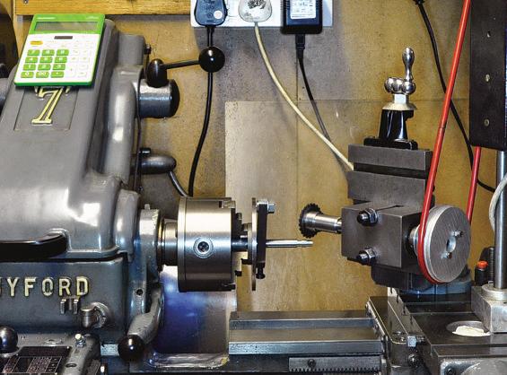
Afer afew iterations Ihad a3-D printed prototypethatI could tryfor sizeand fit on thelathe as seenin photo1.This is agood example of how 3D printing tiesinwellwith moretraditional engineeringinmetal.It’smuch less stressfulmakingmistakeswhen all youneedtodoisprintanother part
Thebasicstructurecan be seenfrom theprototype andthe sketch -there aretwo main parts: thetoolholderitself, and acarrierthatengages with the toolpost. Thetwo partsare then held together with steel dowels andLoctite. What’sonthe back of thecarrier is up to you. Ihavea dovetail to fit my quickchange toolpost butmakewhateverwill fityours.
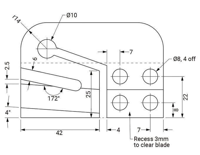
Thedimensions forthe main toolholder areshown in fig. 2.Nothing’s that critical butthere’s notmuch wriggleroom in places
Theblade itselfsits in aslightly dovetailedchannelcut at an angletoensure theblade is supportedfirmly.Itisthen lockedinplace witha tapered wedge adjusted with an M3 screw.
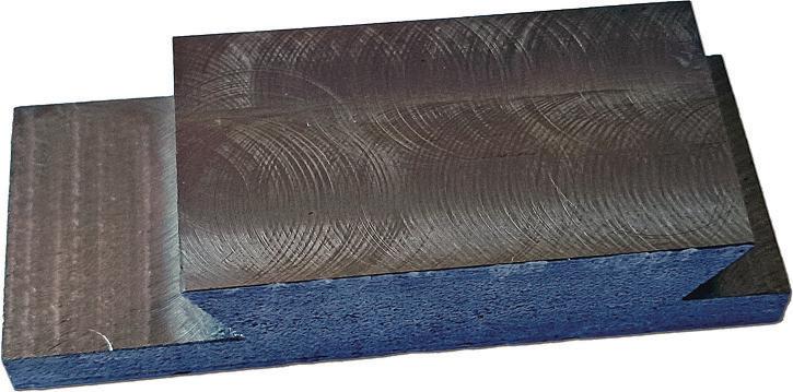
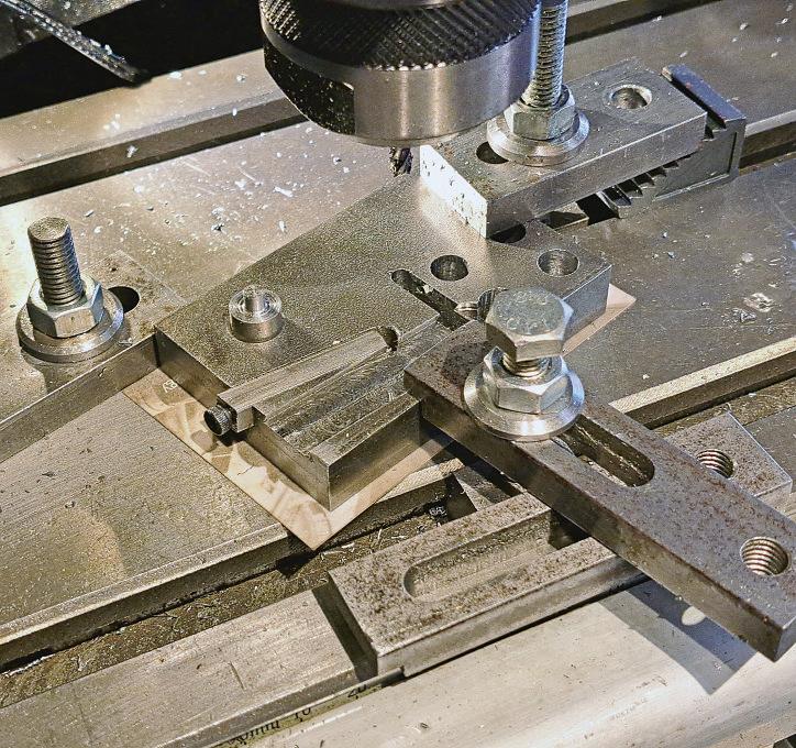
Startbymachining the carrier.I’m notgoing to go intothisasyours will be diferentbut make sure there’senough thickness to supportthe dowels that will hold this to therest of the toolpost.I wouldn’tgobelow 6mm forthis. At this stagemine, having started life as apiece of 16 x30mmmild steel bar, looked like photo3.The dovetails are formyQCTP- yourswill be diferent -justreplace thedovetail with something that will fit in your toolpost. If you haven’tgot heightadjustment in your toolpost then aimtoget the blade at centre heightallowing fora shim for fineadjustment.
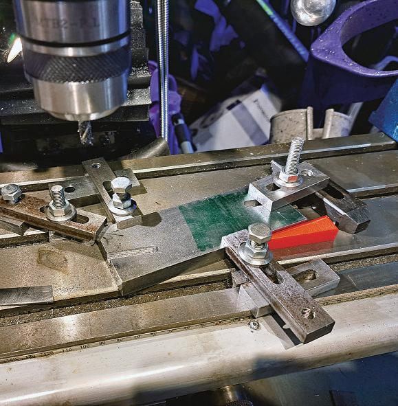
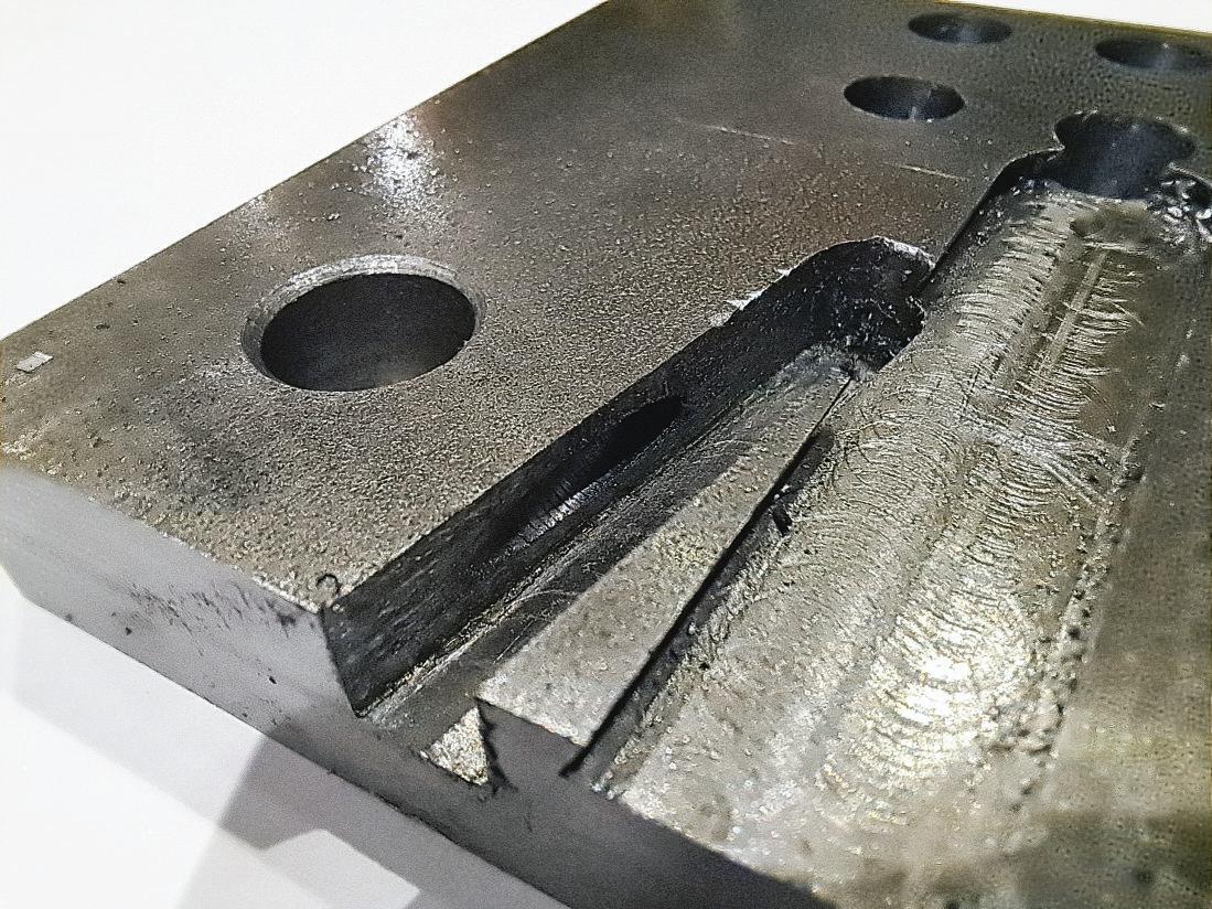
Themain body started lifeasapiece of 2x½”steel barwith one end squared up in themill.Clamped to the mill table thefirst operation is to mill outthe angledslotfor theclamping wedge. In photo3 I’musinga 3D printed angle gaugetoset the12-degree angle. but anyaccuratemethodofseting the angle will do.The wedgeismadefrom 6mm square mild steel so use a6mm cuter to mill aslottoadepth of 6mm. I’msure¼inch could be used instead if that’swhatyou have to hand. Just make sureit’sproperlyclamped down. The marked-out end under the clamps is evidence of aprevious atemptwhere it moved!
Photo 2: Carrier piece.
Photo 3: Initial setup for milling the clamping slot.
Fig1:3DviewfromFreecad.
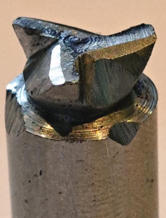
DOVETAILCUTTER
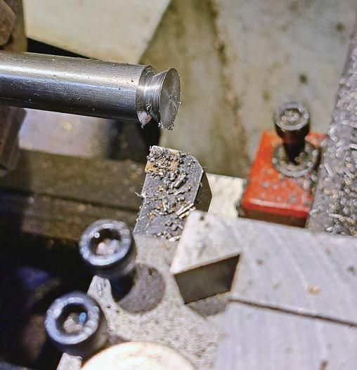
Thenextstepwill be to mill out the pocketfor the parting of blade but here thereneeds to be an undercut to hold the blade in place so,unless you’vegot aminiaturedovetail cuter,you’ll need to makeone out of silver steel. This isn’t dificult andyou’re notlooking fortoolroom accuracy. So first turn adovetail shapeinwhatever diameter(10 -12mm or so)silver steel comes to hand as shown in photo4.Then part of about 50mm -it
just needs to be long enough to hold securelyinyourmill
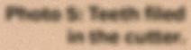
Then,hand-file some teethintothe dovetailpart. Threeseemed to work well and I’msurethe toothshape wouldgive someonenightmares- minedid look abit rough as youcan see in photo5.Once the cuterlooks plausible then harden it by heating untilorangeand plunging intowater.For asingle use cuter Ididn’t bother tempering it anditwas fine. Don’t skip the hardeningstepasitwillbeblunt before you’re finished if youdo.
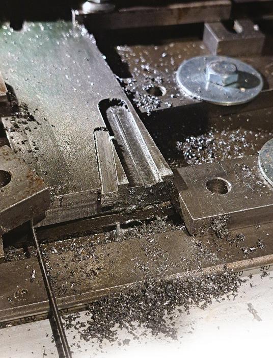
MILLINGTHE BLADESLOT
Havingmadethe cuter the next step is to mill theslotfor the blade. Theblade is taperedsothe workpiece should be supportedatthe topside by apiece of 1.5mmdiameterwiretogive half theincludedangle of the blade. In practice 16swgpiano wire(1.6mm diameter) is close enough.The workpiece is also angled of,thistime 4degrees from theaxis of themill table. Loctite (638 retaining compound)the 6mm
Photo 4: Firststage of dovetailcuter.
Photo 5: Teethfiled in the cuter.
Photo 6: Set-up for milling blade slot.
Fig 2: Dimensions.
squareclamping wedgeinplace so that both thewedgeand themain holder can be machined together.Leave a fewmmofwedgesticking outtohelp remove it later.The set-up on themill is shown in photo 6 -you cansee the pianowirebeing used to setthe slight angleofthe botomofthe slotand also theangle of the slotrelative to the botomofthe holder
Mill the pocket to 3/32" (2.4mm) depth (the width of theblade)atthe deeper side usinganormal endmill. Don’t go to the full width of theparting of blade but allow1mm each side forcuting the dovetails. Then with your silver-steel cuter at fulldepth, andusing plenty of cuting oil, cutthe dovetails. When you’re approachingthe full width,goin0.1mm stepsand use theblade as agauge to endupwith a smooth, slop-free fit of theblade in the holder. Don’t worry about theback-end of the slot- it will be machinedaway later anyway
In photo 6 youcan see theundercutmade by the litle dovetail cuter and also see that the wedgehas been machinedtothe same profile along its last fewmm.
BLADE CARRIER AND WEDGE
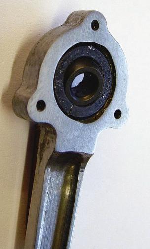
Now’sagood time to cut the toolholder of from the original length of bar-stock and mill to length. Clamp it horizontally on the mill table or in the vice and drill the four dowelholes and the 10mm diameter hole forthe centreofthe spring.Ideally the four mounting holes can be drilled and reamed with the carrierclamped in place also so that the holes line up.The exact position of theholes isn’t absolutely critical, but it is criticalthatthey line up so that dowels can be retained in place without anyfreeplayorslop Because of the dovetails on my carrier part twoofthe holes had to be blind and were finished with aslotdrill.
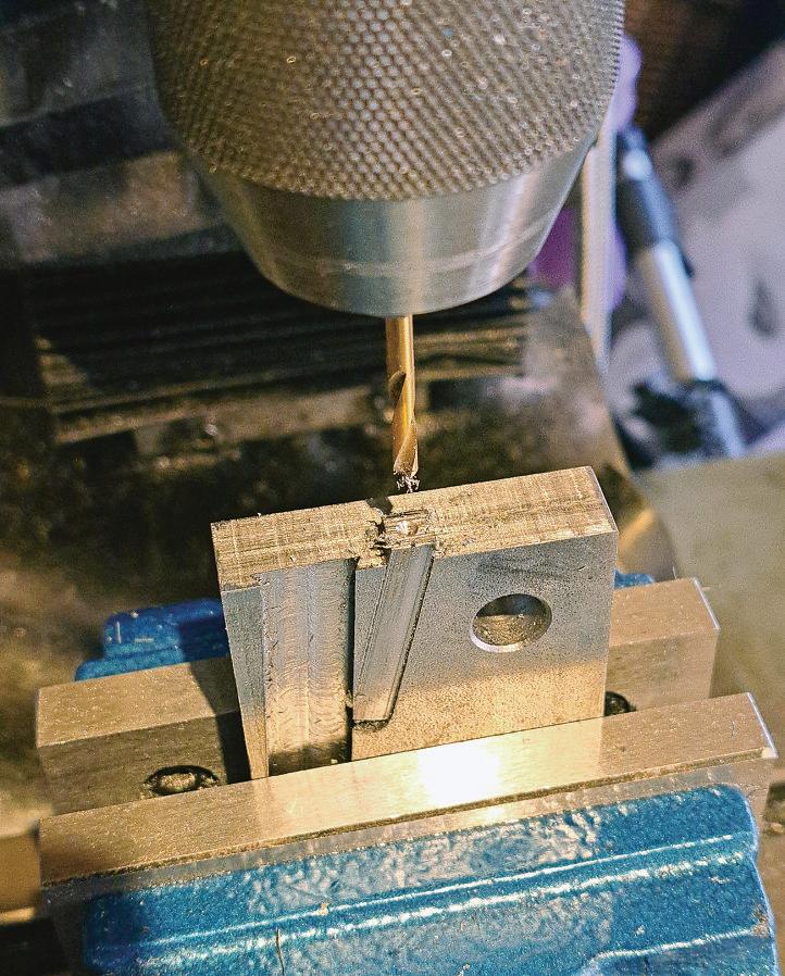
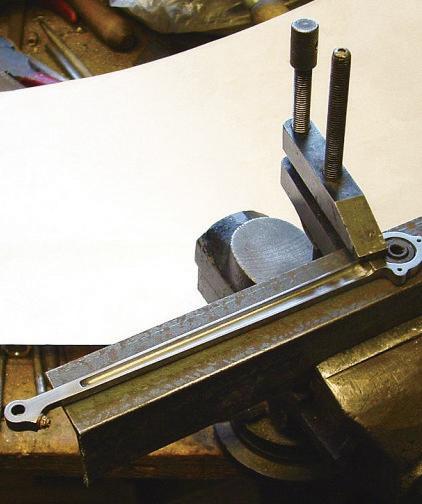
While the wedgeisstill retained in place, mount vertically and drill and tap M3 as shown in photo 7.Ideally this should go to afull 42mm depth so that it reaches the slotthat will separatethe sprung from the fixed parts of the holder
Photo7:Drilling wedge forlocking screw.
Youmight notbeable to tap it to full depthbut it can be further tapped once the wedgeisremoved. It is important to getthe body,not just thewedge tapped though. Finally, start to open out the hole in thewedge to 3.2mm diametertoa depth of about 15mm
Once thewedgehas been drilled you can remove it. Heat it in ahot oven to loosen theLoctiteand witha screwdriver behindand abit of persuasion on the extralength thatisstickingout, it should be possible to free it withouttoo
much efort.
Once freed,put the wedgeback in the vice and continue the 3.2diameterhole to the full depth. Thehole follows the original 8-degree anglebut use the existinghole to setthisinthe vice. It needs a litlebit of slop foradjustment so if the adjustment bolt is abit tight open up the hold to 3.3mm.
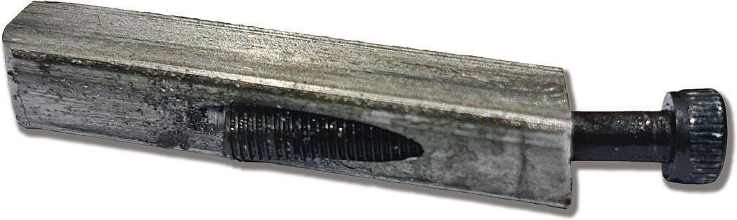
Once that’s done youshould have a part that lookssimilarto photo8 below and atapped holeinthe main holder wherethe wedgeslidesasin photo9
Photo 8: Wedge and locking screw.
ADDING FLEXIBILITY
Once that’sdone, the next stepisto mill the slots in the holder that allow the part that holds the blade to flex whilst the part that’sfixed to thecarrier staysrigid. Firstmill the slotfromthe botomofthe holder up to thespring hole.The first slotissimple enough as it’satright angles to thebase of the holder. Thesecond is slightly fiddly to setupand asimple alignment gauge that fits into the spring hole helps alot as shown in photo 10. Notethe card underneath the part to avoiddamaging the mill table.
Afer milling the slots, radiusthe two topcorners. Iused my rotarytable,but this couldequally well be done with a hacksawand files. If youdouse arotary table, then ashort length of 10mmsteel dowelheld in the chuck will centrethe partnicely on the springhole.The other side wasmarked out and located with awiggler with gentle tapping to getthe partlocated as in photo 11
Thelast machiningsteponthis part is to mill the relief(3mm) behindthe parting blade slotsothat theblade doesn’t come intocontact with thenon-sprung partwhen the holder flexes.
At this point yo us hould ha ve a comple te dh olde ra nd ac arr ier plat e that ma tc hes what ever to olpost se t- up yo uu se on the lathe. Cut fo ur silver st eel do we ls to slightly ove rl ength -o ne end should be turned flat, the ot her can be le ft ro ugh. Lo ctit et he assembly to ge th er with the do we ls also held by Lo ctit e (ret aining compound) in place and allo wt oc ure. Be caref ul when yo u’ re doing this no tt oc ontaminat et he sprung pa rt of the holder to the mounting plat e- yo um ay wa nt to add at hin smear of Va seline where yo ud on’t wa nt the Lo ctit e! Th is is n’ t as harda si tm ight sound as therei s a4 mm slo ts epar ating the bit that is re tained and the bit that isn’t. Finally,p ut the assembly back on the mill and skim of ft he excess on the do we ls so that theya re flush with the surf ace. Yo us hould no wb ea ble to slide the parting-o ff blade int ot he hol de ra nd to snug do wn the clamping we dg ew ith an M3 bolt.
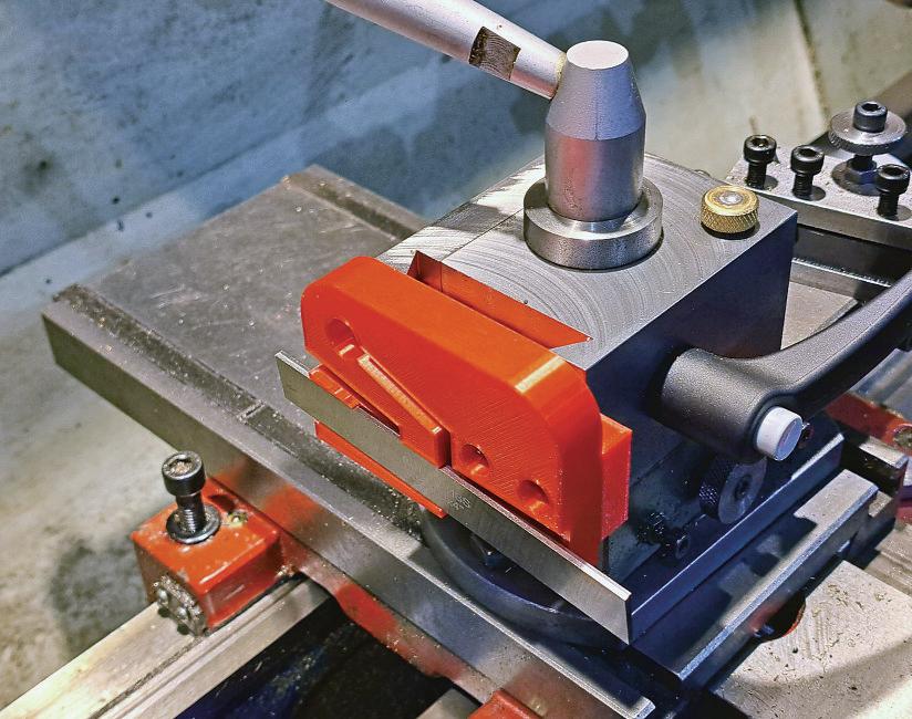
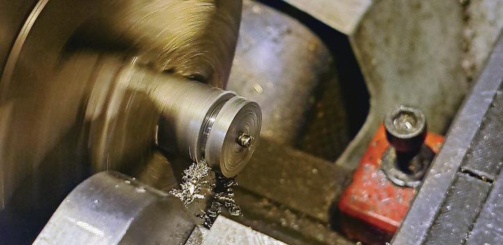
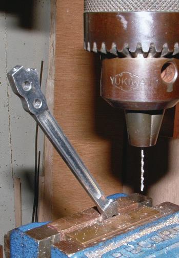
Normal rules still apply when parting of fw ith this holder (e .g .l ock axes that don’t need to move)a nd yo uc an see it in oper ation in pho to 12 .You will no tice that yo u’ re able to use higher speed and the to ol doesn’t te nd to dig in which wa st he whole point of the exercise!
Model Engineer& Workshop
RodJenkins discusses milling in the lathe, a useful skill forbeginners with only alathe at hand.
Alan Barnes describes Chris Barham’s 4” Garret traction engine.
To pre-order your next copy of ME&W visit www.classicmagazines.co.uk or call 0150
Photo12: In operation.
TheBRStandard 2-6- 0Class 4 Tender Engine
THEVALVE GEAR
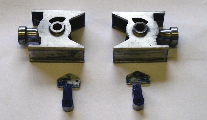
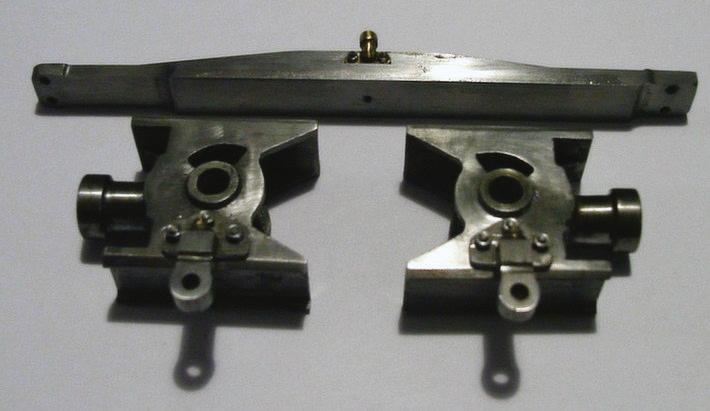
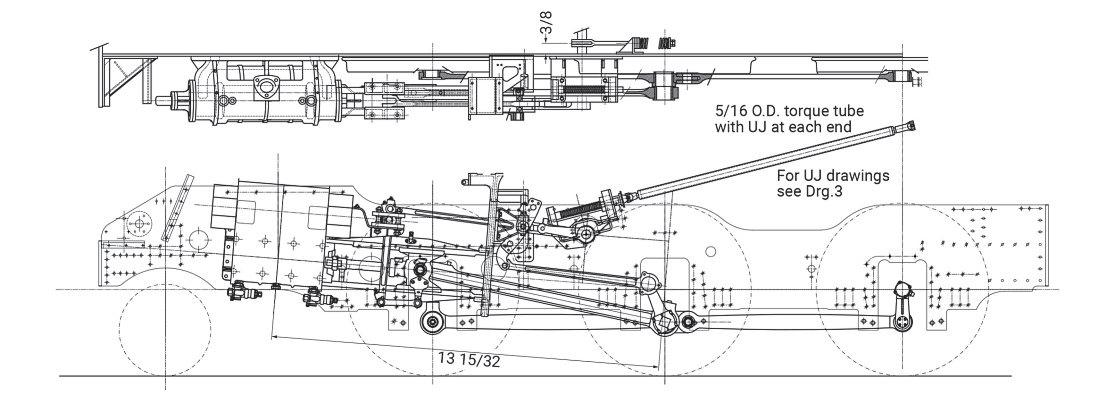
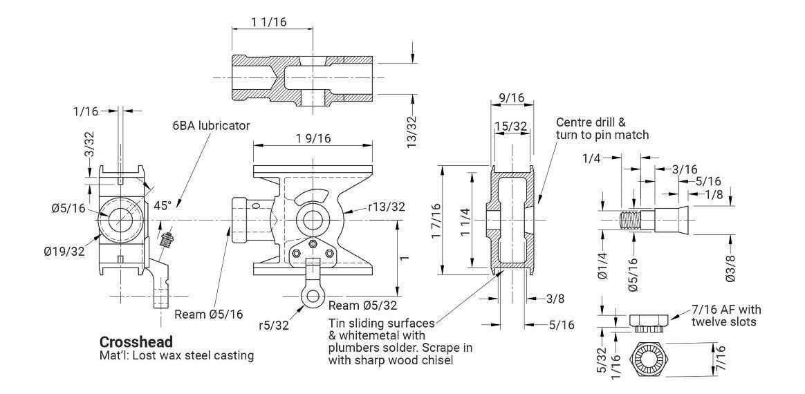
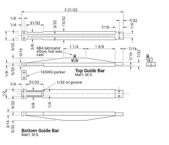
An ot able thing about the BR St andar de ngines is tha ts ev er al of them ha ve similar va lv eg ear, fig 42 , an dt he 2- 6-0 Cl as s4 te nder eng in e is on e. One thing Im isse do ff la st ti me, but shall deal with her e, is the cr ossheads, fig 43 .Ih ad the se cast in stainless st ee l, fo ro bv io us re asons, but the ys till need ab it of mach in in g, such as the ho le fo rt he lit tl ee nd bearing which also re qu ir es cou nt er sinking as we ll as re aming Pho to gr aph 95 s ho ws the p ai r of stainless st ee lc as ing s ;i t’sm y under standing that these ar ei den tica lt ot he Black Fiv es and qu it eal ot of ot her LMS engines. Pho to gr ap h 96 sho ws the cr ossh eads o nce Ih ad cleaned them up al ittle and ro ugh ed ou tt he dr op link s. Pho to gr ap h9 7 sho ws the cr ossheads ag ain but her eIh av ea dded as lidebar, fig 44 , an dy ou can also see ano ther li ttle lo st wa xc asting whic hI made fo r the lubricat or connect ion. Yo ua lso ne ed to re am the hole fo rt he pi st on ro d. One thing Id id wa st ot ry to fo x the ey eal ittle, as the pi nw hi ch fix es
th ec ro sshead to the pi st on ro dw as just as im ple tape rp in but on to po f that Is ilv er sol de re da no va lh ead to ma ke it lo ok lik et he pr oper pin. Of cour se, yo un eed to try the pi n in the hole fir st and then yo uc an judg ew her ei tn eeds the to pc utting of fa nd Ia llo we da bout 10 thou ex tr a, just to be su re .You can ’t see the join!
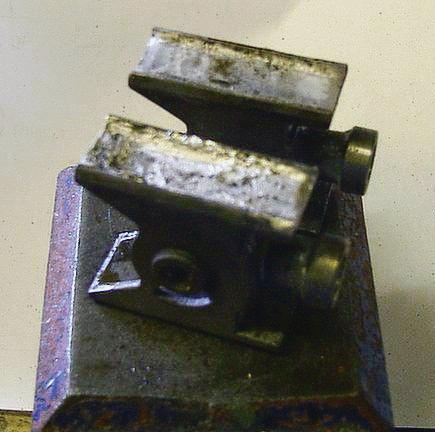
Ano ther thi ng Id id wa st ow hi te me tal the slides. Ih avea no ld to olm aker’sc lamp wh ic hm yd ad made whe nh ewas an appren tice at Scunthorpe Ste elw ork sa nd Ic lamp the ends of the crosshead to fo rm ad am at each end; pou rt he wh it e me tal in and then machi ne it as yo uw ould norm ally.You can ob tain whit em et al from an yb ro ke nt oy
Photo 96: Crossheads cleanedup, with drop links.
Photo 97: Crossheads again with aslide bar complete with oiler.
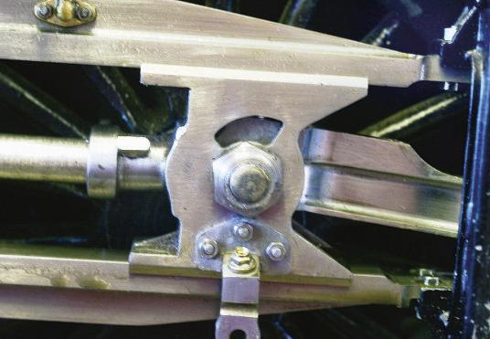
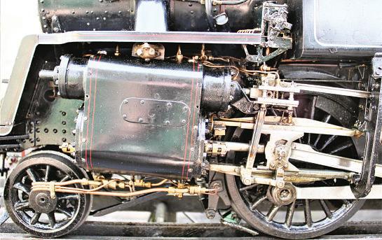
Pho to gr aph 98 sho ws the whit e me tal no wi nt he crosshead slide a nd thi sn eeds mach ining sy mme trically so that the pist on ro dremains in the centre. No w, Id idn’t ge ta re ally go od pho to of the pin which fixes the pi st on ro dt ot he crosshead, so Ia m hop ing th at the production te am ha ve go ta be tt er kit than Ih avef or fixing it! Ac lose-up viewi si n pho to 99 Pho to gr aph 100 sho ws the ro ds and va lveg ear on my 80080 but the pin is half hidden by the co mbination leve r.
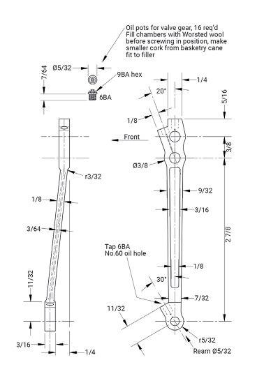
COMBINATION LEVER
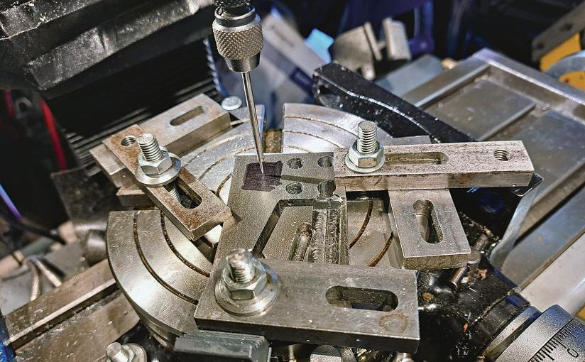
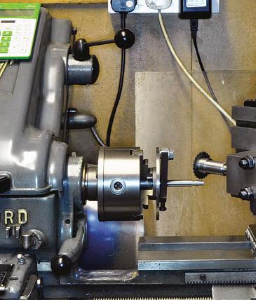
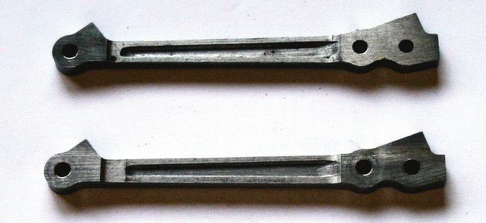
We can no wg et on with the com bination leve r, fig 45 ,a nd pho to 101 sh owst he pair of them. MikeJ ack made these fo rm e, as he had als o done fo r8 0080.Id id, ho weve r, ha ve to drill the hole fo rt he angled oi lh ole an d pho to 102 sho ws my se t- up fo r doing this and as imilar one at the to p. Th ey we re bo th fitt ed with the u su al br ass he xag on fittings screw ed in to the oi lh oles threaded 6B A wherea ppropri at e. Pho to gr aph 103
98:Slides whitemetalled.
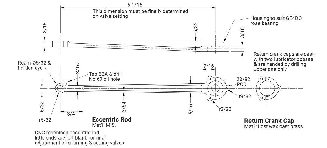
sho ws one of the eccen tric ro ds, fig 46 ,recei ving al ittle sp it an dp oli sh, ag ai nw ith my polishin gs tick, an d pho to 104 sho ws ac lose up of th e ‘rose’s elf-a ligning bearin g. Th ese are excep ti onal li ttle thi ngs an dId on’t kno wh ow man ym ile s8 008 0h as no w run -b ut it’sal ot -a nd Id on’t th ink it is sho wing an ys igns of we ar ye t.
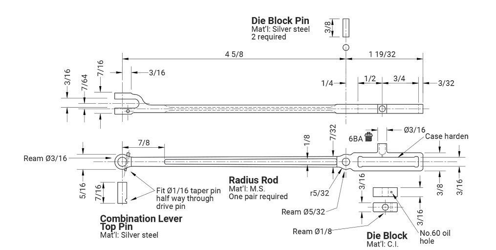
Ih avei ncluded ad ra win gf or th e ra dius ro d, fig 47 in this pa rt be fo re we move on the ex pan sion lin ks , re turn cr ank sa nd va lverods an d guides ne xt tim e.
Photo
Photo 100:Crosshead detail on my
Photo 99:A close view of the crosshead assembled.
Fig: 43
Photo 101: Apair of
Fig: 45
Fig: 44
Photo 103: An eccentric rodreceives someTLC.
Photo 102: Set-up for drilling for the angled oil hole.
Photo 104: The Rose self-aligning bearing.
Fig: 47
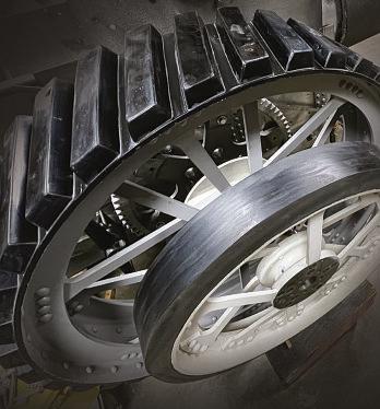
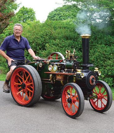
Paul Zeusche,inthe USA, sought a workablealternativetovulcanised rubberfor histraction enginetyres. His experiences will be usefultoanyone interested in casingpolyurethane.
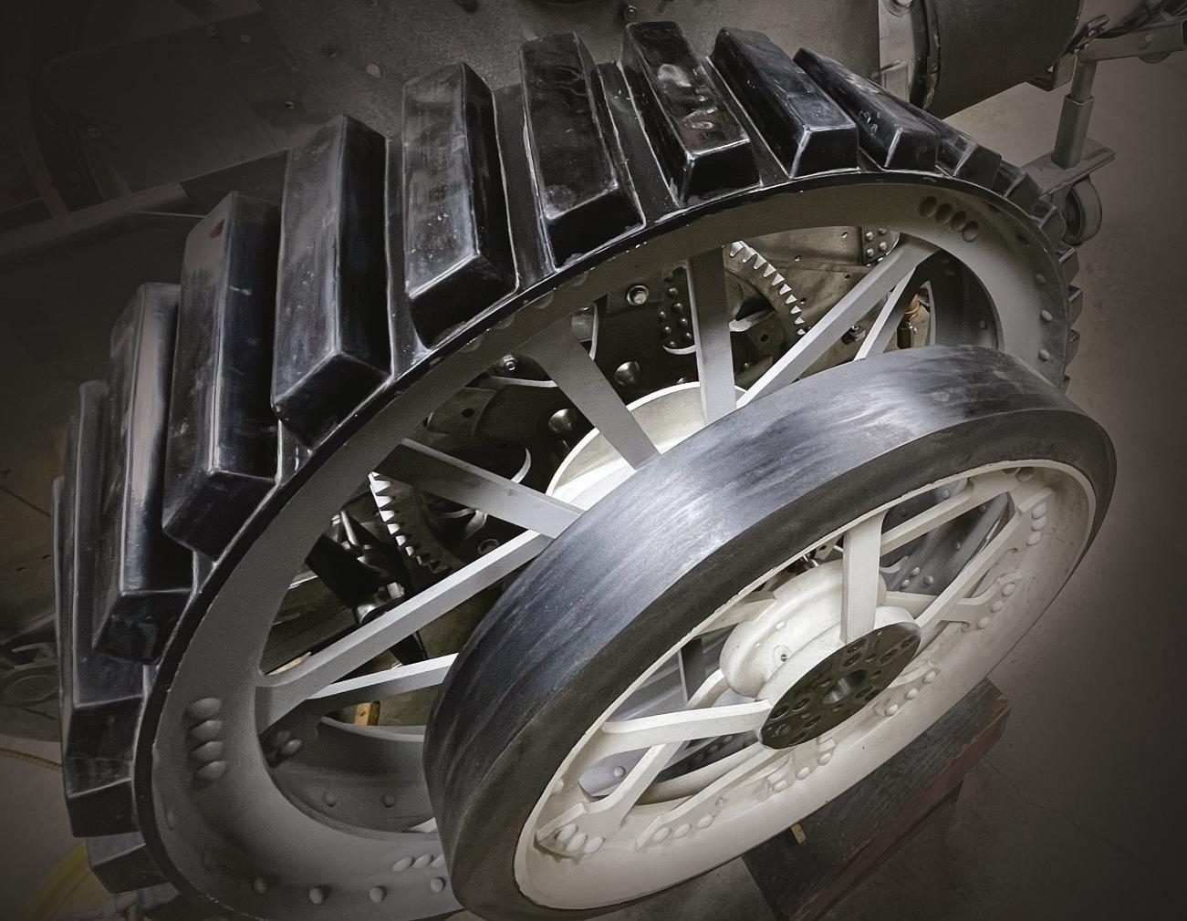
Asthe traction engine hobbyinthe USAdoesn't have the wide following it does in Europe andthe UK, specialist supportingservices in theUSare scarce and even if available, are ofen very expensive. Early on in my build of aDevonshireDCC half-scale traction enginefromcastings from UK’sLitle SamsonModels, while waitingfor the code boiler to be built locally,the wheelswere thefirst major parts to be tackled.
Early enquiries were made forcompleting vulcanized rubber tyres, thelocal prices were quotedinthe thousands of dollars and either of no apparent interest to the vendor or outside their direct experience.AsIliveinarural areadistant from major manufacturingcentres the problemsare further exacerbated. Somuch for the preamble:
Whilst visiting the Great Dorset Steam Fair some yearsago Ifellintoa conversation with theownerofa magnificent full sizeshowman's engine and
noticed theyhad individually bolted and mouldedstrakes ratherthan solid tyres and assumed these were most likely rubber.Apassingmentionmuch later in amagazine notedtheseweremoulded polyurethane and notrubber,but unfortunatelynodetails given
Thehigh cost and uncertainty of local commercial vulcanized rubberled to the subjectofthis article,moulded strakes for the rear wheels and solid cast tyres forthe smaller front wheels at amoreafordable cost andwithin the capabilities of the amateur.Beaware that this approach forstrakes is fairly time consuming and will requiresome tools, equipment and experience youmay not(yet) have in your workshop
Themost time-consumingpartis producing the moulds forthe strakes. As described below, there is anotheroption using aflexible siliconecompound forthe mould and its use is well coveredonthe Smooth-On website; this maybea more
atractiveand less involved option and worthconsidering
Thepolyurethane product (PU) Iused is marketedbySmooth-On andisavailable in the UK and Europe,sothe following procedures relatespecifically to that product. Smooth-On have avery informative websitewith good product information, video guides and safety data sheets for every product.
As this is achemical compound thereis apossibility of personalsensitivity,soall appropriate precautions should be taken when handling the components andwhile mixing and during use. Disposable gloves and safety glasses should be worn as at the very leastitsticks likethe devil.
PU compounds arewidely available in avarietyofformulations and hardnesses, ofen expressed as ShoreA value. Select aslowcuretoprovide adequateworking time.Typically atwo-component mix plus a blackcolouring compound, as without,itis atranslucent amber colour.
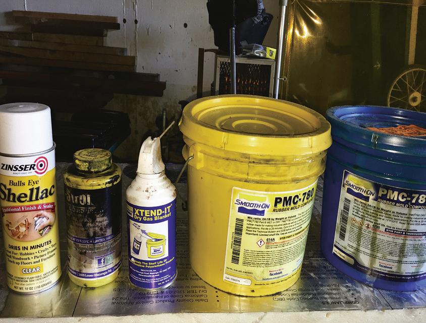
Photo 2: Unwaxedshellac, black colourant,inert gas, and PMC 780 Polyurethane compound, parts A& B.
Photo 3: Translucent test strake, error in insert placement obvious.
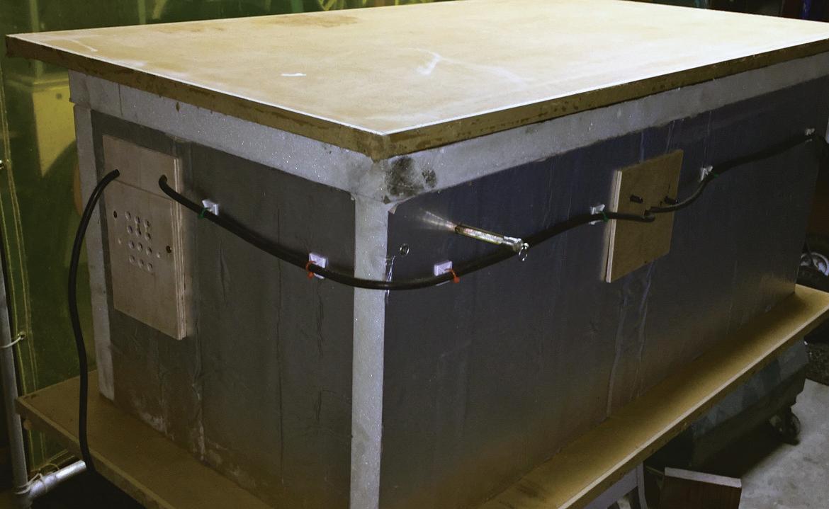
Photo 4: Hotbox made from foil faced 2” insulation board, topisremovable.
My final choice, PMC780 (dry)was sourced direct from Smooth-On, photo 2,represented in the UK with details on their informativeweb site, www smooth-on.com. This is availableina 3lb 'sample'for evaluation purposesand in largervolumes, with amixingratio of twoparts Atoone part B. PCM 780 has aworking lifeofabout 30 minutes and ideally apost cureatover100°F (38°C).
Before commiting to aspecific product Iopted to cast alef andright strake
hand in ‘clear’ortranslucent PU where the insertsare somewhat visible. An error in placement became obvious requiring cutinga flat on the edge of the ofending inserts, photo 3 (see alsophoto 10 later). I’dguessed at ahardness value of 70 ShoreA,but felt this wasultimately toosof so upped the final choice to 80 (PMC80).
Aheated enclosureof‘hotbox’is recommended if using apost cured product.Thiscan be asimple enclosure
made from 2” insulating foam, a 100-watincandescentlight bulb,a computer fanand athermostat with a simple glass thermometertomonitor temperature, photo4.Once adjusted therewas no need to fiddle, and the lightbulb produced enough heat foran adequatepostcure
Digital scales areuseful foraccurate small quantityPUcomponent mixing, widely available online. 1kgcapacity is adequate.