


Welcome to the June 2023 issue of RCM&E.


Welcome to the June 2023 issue of RCM&E.
In the last issue I recalled watching, as a young lad, a segment on radio-controlled aerobatics on ITV’s ‘World of Sport’ programme. I was unable to access the ITV archive to find a clip of this event so I wondered if the BBC had any similar clips. Af ter Googling ‘Model aircraf t BBC archive’ I was rewarded with some segments from 1970 editions of Nationwide, their early evening current af fairs programme (long before the One Show), with one item showing the UK’s top scale modellers of the time, namely Mick Charles, Terry Melleney and Roy Yates. A later episode the same year featured the 1970 Scale World Championships, hosted by the SMAE (Society of Model Aeronautical Engineers, forerunner of the BMFA) which was held at Cranfield. This shows some eyewatering crashes of some very nice scale models, one of which ended up inside the spectator area on the opposite side of the runway – ouch! Some may think that modern day health and safety measures at model shows and events may have gone a bit too far but watching this film really does bring home just how much such changes were needed when presenting our hobby to the general public.
At the bottom of the list of links is a piece from Blue Peter in which John Noakes can be seen steering an R/C Avro Shackleton around the studio f loor, its two inboard glow engines burbling away until swif tly silenced by virtue of John throwing his hanky into the props; the ‘wise way’ to stop the engines, says John… I’m guessing that the engines were set to a fast idle to keep them running during the pressures of the live transmission rather than relying on lower revs and finely tuned carburettors.
Another link takes you to a piece to camera by James Burke, who is seen f lying an R/C Spitfire for Tomorrow’s World – a ‘must watch’ TV programme for young Master Crozier back in 1969, although I have to admit that this particular episode must have passed me by as I have no recollection of it. James’ film ends with a montage of pictures taken of the airfield from a camera mounted underneath another model, leading him to speculate on the possible use of R/C models as spy planes. I wonder what the Tomorrow’s World team would have thought of even the most basic camera equipped drones had they been available back then!
James was of course most famous for his work covering the Apollo moon landings. Finding this clip was one of those rare coincidences that make you think that a higher power must be
at work because as I write this I have been keeping an ear open on the exciting events as the first SpaceX Starship prepares to launch from Boca Chica in Southern Texas. Serendipity indeed!
It’s time now to take a brief look at what we have lined up for you in the June issue of RCM&E, starting with our regular columns.
In his latest Bench Blog, Tim Hooper completes the curvaceous Boomer Bus and then turns his attention to starting a recalcitrant spark ignition engine. In One Man & His Shed sunlight proves to be the saviour allowing Dave Goodenough to keep his f light box battery topped up using solar power. Then it’s over to Chris Williams for more Scale Gliding as Chris sees another senior friendly size scale soarer, a Slingsby Type 50 Skylark 4, make the transition from his drawing board and into the sky. Later on, Keith Jackson’s Aerobatic Scene column brings us up to date with all the latest news from the world of F3A f lying before Graham Ashby and Kick the Tyres in which Graham takes a turn on the committee of his model club, attempts to fashion a silk purse out of a sow’s ear with a sheet foam SE5a and encourages us to consider drawing up a post-f light care plan.
For this month’s centre-fold Pro-Plan it’s back to Chris Williams who introduces part one of his article describing the build and f lying of a classic one sixth scale vintage glider, the Slingsby T.30 Prefect.

Our feature articles start with Contra Club, which discusses if two props are better than one; John Stennard attempts to find out as he tests a new contra rotating propeller system for small models. Next, Stephen Wessel makes use of ping pong balls and hair curlers to fabricate the induction pipework for his half size V8 aero engine. Finally, we join John Bristow from Deluxe Materials as he describes the many and varied uses for Super’Phatic! glue.
On test this month David Ashby f lies a trio of small WW2 fighters from Top RC before Helmut Harhaus concludes this month’s reviews by recreating a pioneering rocket propelled aeroplane, the Opel Rak 1, in model form using the FUNModellbau kit. Little did he know when he started but he was in for quite a wild ride!
I hope you enjoy reading it all.
Happy Flying!








Photo: Chris Williams
Slingsby’s Type 30 Prefect from 1948 was intended as a replacement for the Grunau Baby. Designed by Chris Williams at 1:6 scale and with a 2.4M span this is a perfect stablemate for the slightly smaller Wolf, previously published in RCM&E.
David Ashby f lies a trio of small WW2 fighters from Top RC
Helmut Harhaus recreates a pioneering rocket propelled aeroplane in model form using the FUN-Modellbau kit.


10 CONTRA CLUB
Are two props better than one? John Stennard attempts to find out as he tests a new contra rotating propeller system for small models

42 SUBSCRIBE…
... and receive Luf twaf fe Fighters & Sea Harriers FREE!*


44
In part seven of his ENV aero engine build series Stephen Wessel fabricates the motor’s induction pipework

86 SUPER ’PHATIC!
John Bristow from Deluxe Materials describes a 21st Century glue
16
Tim Hooper completes his Boomer Bus curvy wing bird and then turns his attention to starting a recalcitrant spark ignition engine
Dave Goodenough keeps his f light box battery topped up using solar power before finishing his ‘Beginner’s Bundle’ glider

36
Chris Williams sees another senior friendly size scale soarer make the transition from his drawing board and into the sky
72 AEROBATIC SCENE
Keith Jackson brings us up to date with all the latest news from the world of F3A f lying
Graham Ashby takes a turn on the committee and encourages us to consider drawing up a post-f light care plan
48
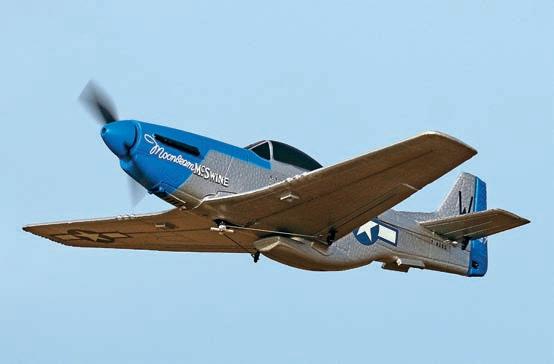
Chris Williams introduces part one of his article describing the build and f lying of a classic one sixth scale vintage glider

All reasonable care is taken in the preparation of the magazine contents, but the publishers cannot be held legally responsible for errors in the contents of this magazine or for any loss however arising from such errors, including loss resulting from negligence of our staff. Reliance placed upon the contents of this magazine is at readers’ own risk.
We were sad to learn of the passing earlier this year of Ian Peacock who was a wellknown contributor to RCM&E, especially during the editorship of David Boddington. Our thanks go to Kit Spackman, a close modelling friend, who sent the following letter recalling his time spent with Ian:
My friend of many years, Ian Peacock died at the end of January, and yesterday I went to his funeral. You might have thought that this was a sad occasion but not so. To give an idea of Ian and his thinking the order of service had instructions for folding it into a paper dart printed on the back. I was expecting some of the congregation to actually fold one up and fly it up the chapel, but they didn’t. His son did fold one and place it on the coffin however, his thinking obviously being that Ian would need something to fly in the life hereafter.
Ian was a total aviation nut and he worked for Vickers at the time they were building Valiants and Viscounts. One of his tales concerned working on the Valiant’s fin 30 plus feet above the ground and they were issued with safety harnesses attached to sprung reels in the hangar roof.
Of course, they were NOT permitted to abseil down the fin while wearing the harnesses - no more needs be written about that…
I met Ian in 1972 at a Birmingham IPMS (International Plastic Modellers Society) meeting and we hit it off right away, both of us thinking slightly off the normal track, and we were both radio control flyers as well, so we had more than one common interest, but both aviation related of course. The radio control aspect broadened into model boats and we both built several of them.
Ian’s plastic kit builds were mainly 1/48 scale, at the time when the Monogram Mosquito was THE kit to have, and Ian built almost all the Monogram range at one time or another. Later he got to like the Tamiya 1/100 scale range and built at least one of every model available, many of them with non-standard colour schemes once I’d developed my home decal printing technique. At one time or another I always had one of Ian’s decal schemes under development on my various laptops.
Ian’s primary interest was flying models, both control line and radio control, with the occasional move into free flight models, and for a while he ran his own firm, Peacock Models, manufacturing kits for radio models in his garagecum-workshop.
Back in the 70s and 80s there was a full-size aerobatic display group in the UK called The Barnstomers, which was headed up by the late David Boddington. David was also a serious aeromodeller (and a well-known editor of RCM&E) and he wanted to add some model flying to their display routine. He asked Ian to put a programme together. I mostly flew R/C gliders then and Ian suggested we have a go at aerotowing a glider from the ground, casting off at altitude and then both the glider and the tow aircraft each
After publishing the highly regarded work of aviation artist Martin Bleasby in the last issue, the author of ‘Creating Your Masteriece’ (pages 84-87) Noel Harvey realised that his article did not contain contact details for any readers who were interested in talking to Martin about purchasing prints or original artworks.


Noel says: Martin does not have a website but tends to market his aviation art on Facebook using the following link: https://www.facebook.com/ MartinBleasbyAviationArtist/ Or you can find him on Facebook: @ MartinBleasbyAviationArtist
doing an aerobatic display. As Ian was doing the commentary on all this, I ended up flying one of my glider designs, a 10-foot span model called a ‘Curved Air’, named after the band and because it had curved dihedral. The towplane was a three times size ‘Purple Haze’ with a hefty glow plug engine and a servo in the tail to release the tow line in case things went wrong. Obviously my ‘Curved Air’ had one in the nose to drop the tow line as well and this idea worked rather well, but only during the test flights of course!

We did our very first public display flight at a park in Matlock in Derbyshire and the 1:1 scale displays were flown from a nearby airfield as there wasn’t anywhere for them to fly from in the park. But we could fly our models from the cricket pitch there. It all went well until the time came to land the models; the tow plane was stooging around waiting for me to land but as I turned the glider onto the approach a whole lot of younger members of the viewing public decided that this nice piece of grass would be just the place to have an impromptu game of football! Despite Ian warning them of the approaching model over the PA, and the entreaties of their parents, they were far more interested in kicking the ball around. I had to do something fast and made a sharpish turn over the fence of a nearby tennis court, popped out the spoilers and brought the model into a landing inside the court. It stopped with the nose poking through one of the holes in the opposite fence! Ian naturally made out that this was all part of the planned display…
Modelling life was never dull around Ian and I’ll miss him and all his crazy ideas very much.
Kit SpackmanReferring to Jim Newberry’s build article for his M.23c early Messerschmitt design, a couple of readers have pointed out that the plan does not include a dihedral template although a template is mentioned in the text:
The ribs can now be fitted accurately in position, ensuring that they are snug on the main spar, the rear tabs are resting on the building board and that each rib is vertical, except for R1, which must be fitted at the correct angle for the dihedral, using the dihedral template as a guide.
Experienced modellers, which this plan is best suited to, will realise that the dihedral is
The Centenary of the first successful flight of the Cierva C.4 autogyro, built by Spanish aviation pioneer Juan de la Cierva, almost passed us by had it not been for an email sent to us by Santiago de Blas Larramendi. In his message Santiago informed us of a model diorama dedicated to this important milestone in aviation built from recycled materials and which is currently on display in the window of his art studio, DeBlas - Estudio de Arte, in Getafe, Spain.
Santiago writes:
In Getafe, the cradle of Juan de la Cierva’s Autogyro, soon after the Centenary (9th January 1923), ‘De Blas- Estudio de Arte’ presents a tribute to the Autogyro and Juan de la Cierva with a scale Playmobil model made using recycled materials. What is it made with?
Blades - Gel bottle
Wheels - Wine carton caps
Wheel support - Clothes hanger
Structure - Ikea cardboard and coffee sticks
Main rotor motor - HP printer motor
Visible engine - VHS VCR motor
The main blades move. We know that originally

Sarik Hobbies are continuing their RCM&E readers’ wood pack offers by giving a generous 10% discount on the wood packs that they have prepared for Chris William’s Slingsby T.30 Prefect scale glider, the first part of which is featured in this issue.

set by the position of the wing tubes in the inboard ribs. However, to save anybody else from searching for the missing template, a sketch is provided here.
Jim says: “That’s annoying. I remember writing that part of the instructions at the same time as drawing the plan, before the penny dropped that I wouldn’t need a template as long as the root rob was set perpendicular to the aluminium tubes, but I should have spotted the section was still in the instructions. I’ve measured the plans and a scrap of wood with an 87-degree angle in one corner will do the job. It’s two ways of skinning the same cat but I can see
why some people would prefer to set the rib with a template and it’s probably better to give them that option, especially as that’s what the instructions will say for any future builders.”
the upper blades moved only by the action of the wind to support the gyroplane, but we have put a motor on them to make them more spectacular when stationary, since our model does not fly.
We created the plans from scratch, generated templates, searched for useful materials, adapted and assembled them to create this non-flying replica, even though the blades move. But I wish it had a better paint finish.
This diorama can be enjoyed in our shop window, located in Madrid, Getafe, Calle Lártiga 2, corner Calle Leganes. There we teach Industrial Design classes for adults and children, among other disciplines. We make our own toys, as well
as enjoy our own world of illusion created for Playmobil. Find us on Facebook: https://fb.watch/ ixNUaQMQEg/
Many thanks for sending us details of your recycled autogyro model Santiago. And thanks also for reminding us of the important first flight of a Cierva designed autogyro
We are sure that there are several R/C scale models of Cierva aircraft, and the associated Avro and de Havilland based designs, so why not send us some details and a picture or two if you are the proud owner/builder of an appropriate R/C scale model autogyro.
Please visit the Prefect page of the Sarik Hobbies website: https://www.sarikhobbies. com/product/slingsby-type-30-prefect-90-55/ Since the wood packs will not be ready until the second part of the Prefect plans are published in the August issue, please bookmark this link and revisit to take advantage of the offer when available.
This is nothing to do with contrary club members (who has those anyway?) but is to do with flying models using contrarotating electric motors. In general, if you fly a model with contra-rotating props you are likely to be an F3A pilot or indoor F3P ultra-light wizard. If so you will be using high end units designed specifically for a demanding style of flying, often in a competitive environment. For the average modeller contra-rotating motors (CR from now on) can be a complication too far and it offers few advantages over a conventional power system.


 » John Stennard
So why use this motor system? As far as models are concerned it eliminates the torque action and for competitive aerobatic flying this is a valued function. For indoor models larger and slower revving props can be used, enabling models to be flown very slowly. Of course, some very iconic full-size aircraft have used CA power and there is an attraction in replicating them in a scale model with a functioning CR unit.
But, as far as I was concerned, I just liked the idea and I saw it as an opportunity to try something a bit different. There are several CR units of different sizes available commercially and I have tried a variety of them.
These all flew the models well whilst making a unique sound.
But before launching into these it’s worth a quick look at the historical full-size scene.
“…I just liked the idea and I saw it as an opportunity to try something a bit different”
To balance out the technical and engineering difficulties of a CR system it should give comparable power and/or efficiency as a conventional power system, plus give the benefits of reduced torque effect. Research led to two design variations for CR systems: one engine driving both props or use an engine for each prop.
The superb Martin Baker MB5, which first flew in 1944, used the one engine system. Capt. Eric Brown said, ‘In my opinion this is an outstanding aircraft.’ Power came from a single Rolls-Royce Griffon 83 liquid-cooled V12 engine driving three-blade props.
The Spitfire was developed into the Spiteful, with a laminar flow wing, and this was further developed into the Seafang. This was a naval version with the Griffon CR engine and it first flew in 1946. Eric Brown was less happy with this aircraft due to its stall characteristics.
By this time jet fighter development had taken centre stage so further development was abandoned. However, the contra-rotating system still seemed to offer advantages for certain aircraft designs, particularly naval types and this led to three iconic aircraft: the Wyvern, the Shackleton and the Gannet.
The Westland Wyvern was designed for CR and was powered by a 3,500 hp (2,610 kW) Eagle engine driving large and distinctive CR propellers. The first flight was in 1946 and 127 were built. The next aircraft in the contra line up was the Avro Shackleton, first flying in 1949 and 185 were built. Initially Merlin engines were used but these were replaced with the larger, more powerful Rolls-Royce Griffons with 13ft (4m) diameter CR propellers. For the Gannet, Fairey selected an engine based on the Armstrong Siddeley Mamba turboprop, the Double Mamba (or Twin Mamba). This utilised two Mambas mounted side-by-side,
coupled through a common gearbox to coaxial CR propellers. The Gannet first flew in 1957 and 303 were built. The Shackleton had a long and successful service life and was only retired in 1991. However, maybe this was due more to there being no replacement aircraft being immediately available, until the Nimrod entered service.

I know that several ingenious and very capable modellers have built and flown successful CR powered aircraft using their ‘own design’ power systems. I am not a member of this league of gentlemen, but I have always been interested in different approaches to powering model aircraft.


The first CR unit I purchased was quite small. It used 3-blade 5-inch GWS props and it appealed to my interest in small models. The design made the unit quite difficult to mount and it required two ESCs to function correctly. Initially I installed it in a small foam Sea Fury and I was pleased with the results. The model certainly flew no better that it would have done with a standard single motor, but it had an interesting alternative propulsion system and sound. I later modified this model to look like a bit like a Gannet – well, from a distance, anyway! It flew fine and looked surprisingly good in the air.
The second contra-rotating unit was much bigger and equally difficult to mount. The PJS
Small CR unit in my foam Sea Fury. The Sea Fury flew no better that it would have with a single motor, but it had an interesting alternative propulsion system and sound.unit used 2-blade 8 x 6-inch props. I fitted this in a semi-scale Tucano, and it required two 20A ESCs and two 3S flight packs. The model flew nicely but again it was no better with the contra-rotating props. It was just a bit alternative and sounded good. This added a different dimension to the model and its flight performance, and it always created interest.
CR REVIVAL

I had not actually planned a CR revival but when I saw the DZP30 unit my dormant interest was awakened. The DZP30 is a beautifully designed and made unit with two 1500kV motors driving conveniently sized GWS 3-blade 7035 props. It features an easy-to-use mounting system and I was delighted with the unit, which weighs around 35g. Using a 3S LiPo the quoted thrust is 240g per motor. Tests have shown that it will operate using a single 20A ESC providing the throttle is opened slowly. However, two separate ESCs do improve the handling and performance. Not wishing to build a scale/semi-scale model until I had tested the motor’s potential, I utilised a redundant model donated by a friend. It is larger than required but it gave me an idea of the performance of the motor unit before embarking on a more suitable design and build project. But it definitely won’t be a Shackleton!


Flight tests have shown that the motor functions really well in the 800mm (31.5”) wingspan X-PLANE test model, with an AUW of 433g (15.3oz) using a 3S 1000mAh LiPo. The unit ran very smoothly, and I could roll and loop the model with ease, so it is definitely a motor with potential.
Feeling really pleased with my first flight using a 3S 800mAh LiPo, I fitted a 3S 1000mAh for my next flight. This pack produced an even better performance and a more suitably sized model would, of course, enhance this further. I am still enjoying flying the X-PLANE so currently I have no plans to fit the DZP30 unit in another model.
Gannet flew well and had a very interesting motor sound. PJS system was a much bigger CR unit. The semi-scale Tukano suited the PJS unit.“I have always been interested in different approaches to powering model aircraft”

The small original small CR model and Gannet conversion date back to 2013 and eventually they became unfit for service. However, you can’t keep a good idea down and the small CR unit is available again as the DZP13 or YX-13DZ. It is the same basic unit but now has a really neat mounting and is available as a package, complete with two 7A ESCs and 3-blade GWS 5 x 3 props. Unable to resist, and with a new Gannet in mind, I ordered the unit via Aliexpress.com. It arrived very quickly and after fitting the motor mount (beware the microscopic screws!) and following a power connector swap, I was able to test it. Although the motor unit only weighs 13g, once connected to the ESCs and with the props fitted the AUW rises to around 34g. So, not exactly a heavyweight combo and the thrust is listed as 180g.


 Tukano flew well and was quite aerobatic.
DZP30 contra-rotating unit for indoor models is just under 4cm long from the back of the mount to the tip of its shaft.
Although larger than required the X-Plane makes a good test bed.
DZP30 motor unit gives plenty of power for steep climb outs
I soon had the motors running in the advised directions, the rear anti-clockwise and the front clockwise. Prop fitting is unusual as the rear prop must be a tight push fit on the shaft while the front prop uses a standard prop adaptor. The video of setting up the motors and props shows that the hub of the rear prop is carefully enlarged to 5mm so that it is a tight push fit on the shaft. In fact, the supplied props already had a hole slightly larger than 5mm. This means that the prop is not at all tight on the shaft. I was very reluctant to glue the prop on and was thinking along the lines of putting heat shrink tube on

the shaft and making an enlarged hole in the prop when I remembered I had some props of this size. A quick check showed that these had a smaller hole and were a tighter fit on the rear shaft. The front prop uses a plastic insert to reduce the size of the hole to suit the front prop shaft. Different batches of these props must vary slightly, which would normally not be a problem. Tests showed that the CR unit ran well but I was unhappy with having so many connectors. So, I disposed of the Y-lead connector used to couple the ESCs to the receiver by soldering the ESC leads to a single Rx connector.
Twin XP-7A ESCs are supplied with the DZP30. However, it will operate using a single 20A ESC providing the throttle is opened slowly.


This motor is destined for a new purpose-built Gannet. This will have a 6mm foam / 3mm ply / 6mm foam sandwich fuselage and a 6mm foam wing of 500mm span. The tail parts will be from 3mm foam. There are quite a few challenges with the design, so it won’t be a fast build. Both the DZP30 and DZP13 are available online, as are several other larger units. Check them out at Aliexpress.com. It is always rewarding to try new motor and airframe opportunities and fitting these CR units into models and enjoying a different flying experience has been very satisfying.
X-Plane has proved to be a really nice model to pilot and with the CR unit it has a good turn of speed if required.
“This motor is destined for a new purpose built Gannet”








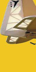

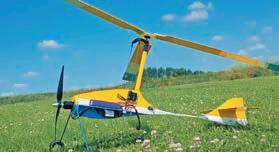


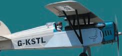
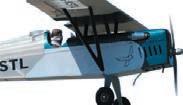


Tim Hooper completes his bent wing bird and then turns his attention to a recalcitrant sparkie engine words & photos » Tim

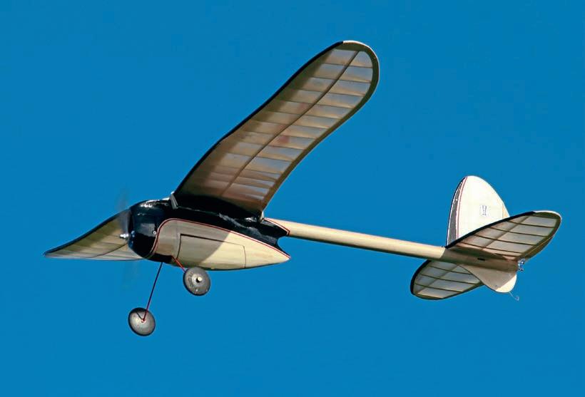
At last, we’re at the end of this journey to build the somewhat unusual Boomer Bus, which hails from the pen of Henry Struck, way back in 1941. We’re up to the final assembly.
Those 2 1/2” wheels are treasure from a swap meet. They are genuine Keil Kraft rubber streamliners and heft in at over 3oz for the pair. Obviously, relics from the short-nose days of aeromodelling when heavy wheels could double up as usable ballast.

Henry Struck’s 1941 Boomer Bus was designed for IC power but makes an ideal vehicle for a modern electric conversion. A ‘proper’ builder’s model that won’t be hurried - either on the board or in the air.
HooperThe plan shows some rather swoopy, streamlining fillets of 1/32” balsa sheet to cover the fuselage joins and these were next on the agenda. I opted to complicate things by using 1/64” ply for these fillets as they’ll help to reinforce the joint betwixt pod and boom. Given that the fillet pieces would have to adopt a compound curve as they rounded over the fuselage, I dunked them in water overnight to try and soften them up a bit.
The next morning, I was able to persuade the first fillet to conform to the desired, concave shape. Using a combination of glue, pins, scraps of balsa dowel and elastic bands, I secured the fillet in place whilst the glue dried. The opposing fillet, on the other side of the fuselage, followed suit a day later. After all, we’re not in a rush, are we?
The ply motor box has 3° of downthrust built into it and I eyeballed in a little bit of side thrust too using packing washers under the motor’s lugs. Using the prop adapter as a foundation, I cut a tear-drop shaped piece of 1/16” ply to act as a front former and bolted this to the front of the motor. Installed, and with the front former vertical, I wrapped the motor with masking tape, not only to stop it rotating but also to keep the inevitable sawdust out of its innards.
OVAL COWL
That unusual cowl was formed from scrap balsa block and I used the old trick of applying Sellotape to the motor box where I didn’t want
the cowl to be installed permanently, prior to building the cowl in situ. The most joyous part of the project so far was breaking out the belt sander, then roughing out the shape of the cowl. It’s quite intricate, with three areas that are concave, so I carefully used the very end of the belt where it passes over the end roller to give a tighter internal radius.
As space was tight in the nose, I spent some time pondering the fitment of the ESC and its attachment to the motor’s wires. After trying out various ideas for routing the wiring, I hit on the idea of passing the three cables under the cowl, and then between the undercarriage and its mounting plate, and then into the front of the pod. The only snag with this scheme was that the wires would interfere with the front face of the large belly hatch, so I fabricated an internal, open-fronted box in the hatch to accommodate the ESC cables.
Whilst I pondered the cowl and hatch, part of me was also wondering what to do at the tail end of the boom about mounting the tail surfaces. Should the tail set be fixed in place or removable. Where to run the control linkages? The original design calls for a banded-on tail set in the interests of

free flight flexibility. But that can inevitably lead to unwanted movement and loss of trim settings.
Whilst I deliberated all these esoteric issues, I ploughed ahead and fitted a curved mounting plate, which was inset into the top of the boom. The plate matches the curvature of the underside of the tailplane pretty exactly. This was achieved by using the tailplane itself to hold the mounting plate in place as the glue dries.
Very nice, but it still didn’t help my dilemma very much. Eventually, I hit upon what seems to be a reasonable compromise - a dowel at the leading edge and a piano wire clip at the rear.

Given that there’s a gap between the tailplane’s central ribs to create a slot for the fin to sit in, I glued a length of bamboo skewer chord-wise on the lower surface, with front and rear ends protruding. A quick rummage in the gubbins drawer yielded a short wing bolt with a flattened finger grip, which I was able to drill to accept the dowel. I then drilled into the top of the boom, and into the central keel, and let the wing bolt self-tap itself downwards. With the drilled finger grip set at 90°to the boom I can slip the tailplane’s front dowel in place, leaving just the trailing edge to accept the swinging clip.


With all the airframe’s components pretty much sorted, I had a think about the covering material. Thinking back, our last foray on the Ghost Rider project led me, once again, to go the Doculam/tissue route on the open-framed areas of the flying surfaces.
The underside of the wing came first. Given that its gull-wing format gave it a large undercamber when viewed from the front, I applied the Doculam working from the centre outwards, tacking it to each rib in turn, before zapping the whole panel, one rib bay at a time with the heat gun. The wing’s top surface was treated similarly, although I only covered the open areas rear of the top spar.
Carnival Papers tissue was next on the agenda. Previously I’ve applied this budget paper pre-damped and doped it in place. This method works well but can leave the tissue with a mottled, bloomed finish.
This time I applied the tissue dry and attached it to the edges of the framework with a glue stick. Only then was it sprayed with water. The underside of the wing panels was no problem but I was expecting to struggle with the cambered top surfaces. I covered each top surfaces in three separate pieces of tissue to minimise the amount of shrinkage required.
This disc and belt sander has proved very useful over the years. The pulley end of the belt produces beautiful concave curves if used carefully. The cowl is blended into the fuselage’s fillets. The battery hatch was separated later. Tailplane seat is a gently curved piece of 1/8” balsa sheet.The end result does have a few wrinkles, it’s true, even after a couple of coats of thinned, shrinking dope. More surprising was that even though the wing panels were pinned back in station on that bent building board as the dope dried there’s a significant, but equal, amount of washout on both panels.
The leading edge of the wing was covered in span-wise strips of black Profilm, followed by a thin trim line of red Solartrim. An appropriate logo was comped up on the Cricut vinyl cutter and the end result looks pretty swish, I think.

The fuselage and access hatches were covered by simply doping on panels of tissue paper. This took longer than expected, I’ll confess. The interior of the cowl was given a coat of fearsome red enamel, as was the undercarriage.

What did show through the tissue finish on the pod, though, were those streamlining fillets of dark brown ply. So, I masked some swoopy curves with low tack masking tape and filled them in with water-based black enamel. There was a little bit of bleeding under the tape afterwards but a gentle scrape with a knife point got rid of most of this. Red Solartrim pin stripes followed the outline of the black areas and I used a coolish iron to coax the tape around the curves, sticking it in position as I went along.
The next stage was final assembly. Experience tells me that even though I’ve assembled the airframe and all its fittings several times already, and so this should be the work of a single evening, the final fit-out always seems to take ages.
First up came those skinny pushrods and the question of just how to fit them inside that long boom now that both ends were sealed. The penny dropped that all I needed to do was to drill two holes in the front bulkhead so I could feed the rods in from the front and then guide their rear ends out through slots in the tailplane area.
The elevator pushrod is dead conventional and exits beneath the tailplane. But the rudder rod is a little less aesthetically pleasing in that it runs over the top of the tailplane. No matteras long as it works as it should.

Suddenly, I had a completed aeroplane on the bench! I eyeballed the CG position and added a lump of lead within the cowl to drag it forwards to around 35% of the chord, which seemed about right. Completed weight (including the 3S 1800mAh LiPo) turned out at 29oz and with 170 watts on tap I had no worries about the power loading.
 The tailplane’s rear dowel is caught by a swinging piano wire clip to allow for easy removal.
Just to be on the safe side I screwed a chunk of lead to bring the CG forwards a little.
SUNNY MAIDEN
The very next day happened to be a sunny Saturday and so the Boomer Bus was taken to the field for its debut. I was a bit hesitant, given the gusty crosswind, but having taken the static shots I braced myself appropriately and took the Bus out to the flight line.
I opted for a pukka take off, as opposed to the relative safety of a hand launch and pointed the model into the wind. As the throttle was eased forwards the Bus tracked dead straight for a few yards and then lifted cleanly, heading skywards in a perfectly straight line.
The remainder of the maiden saw quite a few circuits at a reasonable height. I didn’t risk any low camera passes in the crosswind. The landing was simple and gentle, with no drama. Subsequent flights were with my clubmate, Trevor, on the sticks whilst I took a few snaps. Trev remarked that the Bus was remarkably smooth and relaxing to fly, which is very affirming, because he’s not an easy bloke to please. Should I have done anything different? Well, even on full rates, the rudder is very soft - more advisory than authoritative. So, yes, if I’d been a bit smarter, I’d have made the rudder about
50% larger, which would help at low airspeeds, such as when making that final turn into wind when on the landing approach. Never mind, she’ll stay as she is!


So, there’s another keeper for my everincreasing fleet of oddball vintage models.
O&R SPARKIE

Ever start a job that should be oh-so-simple, but which turns out to be a lengthy saga instead?
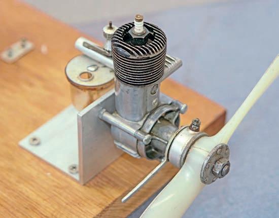
Some while ago my old mucker, Ian Easton, sent me a rather splendid Ohlsson & Rice .23
Viewed from below, the ESC cables pass between the undercarriage and the battery box, and then into the fuselage pod.sparkie that was built in the USA sometime during the 1940s. That makes this 3.76cc engine nearly eighty years old.
It hails from an age when a model engine needed an ignition system to give life to the miniature spark plug using a high-tension spark from a coil. The coil is triggered by a set of contact points within a circular housing just behind the prop driver. There’s a spindly lever sticking out sideways from this housing, which lets the user rotate the housing to alter the ignition timing and thus optimise the point at which the plug fires.

I know very little about the vagaries of IC engine theory, but I do know that as the revs increase then the spark needs to happen earlier - well before the piston reaches the top of its compression stroke. These days our model engines do this automatically but the O&R pre-dates such niceties and has to be adjusted manually prior to launch.
This engine needed the aforementioned ignition coil too. Pukka vintage coils are available but they’re not cheap and neither are modern repro items. But as I didn’t
really know if the engine was a runner or a paperweight, I didn’t want to spend a lot of money. Famous last words, really.
The engine doesn’t sport the usual beam mounts but has to be secured by the through bolts that hold it all together, so I fabbed up a radial mount from angle section aluminium, which then got screwed to my favourite bit of wooden plank. Still unsure about the ignition system I’d need, I also added an empty ice-cream tub to hold any necessary bits and bobs.
Thinking I was being clever, I bought a cheap 12V motorcycle coil from eBay and hooked it up to a 3S LiPo. The negative lead went to the engine itself, the positive to the top of the spark plug and the low-tension feed to those decades old contact points.
I flicked the prop a few times and there was an audible ‘pop’ as the coil burned out with that smell that’s peculiar to fried electronics. It was then pointed out by my online buddies that even a 12V vehicle doesn’t
benefits from some gloopy oil to help it to seal effectively.

always supply the full voltage to the coil but drops it through some sort of resistor. Try again, Hooper.
I bought a second coil from the same supplier but this time I used a lower voltage 2S LiPo as a power source. This looked a bit more promising and there was a definite spark at the spark plug - sometimes. I suspected those aged and oily contact points of being less than reliable, so I spent a happy hour stripping everything down, cleaning and re-facing the points. Trouble is, they live in an oil-soaked environment which just isn’t going to be conducive to long term conductivity.
Just for fun, I inspected the spark plug that came with the engine and saw several hairline cracks in the porcelain insulator. Indeed, further testing witnessed stray spark paths up and down the outside of the plug. New plug, please.
This 1940s Ohlsson & Rice seemed so innocent at first, but it heralded the start of quite a saga!It’s a pretty engine, you’ll agree - although that rearoverhang will take some accommodating when it finally gets an airframe around it. Alchemy! This old engine predates modern CNC machining so the piston/liner fit