DISTRIBUTOR CATALOG
www.flexfab.com
Authorized Wholesale Distributor This is part of our brand name library available at: www.HoseWarehouse.com/catalogs
Bulk Pricing Trained Techs & Customer Supoort Quick Order Fulfillment Product Warranty Product Traceability Recall notification
HOSE
Warehouse
THE FLEXFAB CREED VALUE FOR CUSTOMERS:
We believe our first commitment is to our customers. In meeting their needs, everything we do must be of high quality. We must constantly strive to reduce our costs, and improve our quality and productivity. Customers’ orders must be serviced promptly and accurately.
QUALITY OF LIFE FOR EMPLOYEES: We are committed to the general welfare of our employees and the belief that each must be treated as an individual. We must respect their dignity and recognize their merit. There must be a sense of security in their employment and compensation must be fair. Employees must feel free to make suggestions and complaints. Working conditions must be safe, clean, and orderly. There must be equal opportunity for employment, personal development, and advancement for those qualified. The worth of an employee must be recognized by providing challenging work. Adequately trained and educated employees are necessary in maintaining our quality of work life. We must provide competent management, whose responsibility is to accomplish our long term goals and objectives. Their actions must be just and ethical.
SERVICE FOR COMMUNITY:
We are committed to the communities in which we live and work. We must be good citizens by supporting community projects and charities both financially and with time and talents of employees. We must encourage civic improvements and better health and education. We must maintain, in good order, our property and protect the environment and natural resources.
BENEFIT FOR SHAREHOLDERS: Our final commitment is to our shareholders. The long term viability of the corporation must be assured. New products and capabilities must be developed. New ideas must be encouraged and experimented with. Research must be carried on and innovative programs developed. Facilities and equipment must be properly maintained and replaced when necessary. To meet this commitment, adequate profits are necessary, as well as reserves for adverse times. With a fair price for our products and keeping costs under control, the shareholders will realize a fair return.
Engineering trust. Around the world.™
Flexfab GR 4440 44th St. SE, Kentwood, MI 49512, USA, Phone: 888-353-9323, Fax: 888-353-9344, www.flexfab.com All rights reserved. ©2017 Flexfab Horizons International, Inc. A member of the FHI® family of companies. Flexfab® does not assume any liability for errors or omissions. ZZZ-34693G – January, 2021
BENEFITS AND APPLICATIONS OF SILICONE RUBBER WHY USE SILICONE RUBBER WHEN SO MANY OTHER ELASTOMERS ARE AVAILABLE? STABILITY: Silicone rubber components have a useful life far superior to other elastomers under conditions that would cause those other materials to deteriorate. It has excellent resistance to many chemicals and fluids commonly encountered in service, which is particularly useful at temperatures which prevent the use of other materials.
SILICONE’S STRENGTH IN HARSH CONDITIONS: RELIABILITY: Silicone rubber consistently offers better performance under normal conditions, but it really shows its strength under the most extreme conditions industry can dish out. No matter the application, silicone rubber is the obvious choice for stability, reliability, and value. Visit Flexfab.com to learn how Flexfab’s range of Silicone products can improve your company’s systems...and your bottom line.
FLEXFAB SILICONE PRODUCTS: The uniqueness of silicone rubber provides its users with mechanical, thermal, electrical, and chemical attributes not found in other elastomers. Resistant to hostile environments and damaging elements; strong yet flexible; long service life; are the key ingredients in setting silicone rubber products above the rest.
2
From flexible hose, ducts and sleeves, to high temperature gaskets, electric heat tapes, conveyor belting, etc…. silicone rubber products have proven to provide above average protection from potentially harmful elements.
SNAPSHOT: FEATURES AND BENEFITS • Resistant to a wide range of temperatures • Resistant to hardening, cracking, ozone attack, sunlight • Resistant to moisture, steam, dust, aging, various pressure ranges • Resistant to many chemicals • Retains flexibility in hostile engine environments • Excellent electrical insulating properties • Longer life than EPDM (black rubber)
Phone: 888-353-9323 Fax: 888-353-9344 Email: distribution@flexfab.com www.flexfab.com
CONTENTS 5515 and 5500 Series 3-Ply Coolant Hose
4-5
7701 Series Fiberglass Reinforced Turbo Sleeves
5581 and 5501 Series 4-Ply Coolant Hose
6-7
7703 Series Heavy Duty Fiberglass Reinforced Turbo Sleeves 36-37
8-9
5415 Series 3-Ply Glossy Coolant Hose
34-35
7851 Series Meta-Aramid Reinforced Turbo Sleeves
38-39
5508 Series Wire Reinforced Coolant Hose
10-11
2005 Series Sil-Fab2™ Wire Reinforced Duct
40-41
3000 Series Coolant Hose Kit
12-13
7884 and 7896 Series 3-Ply Silicone Elbows
42-43
High Temp Coolant Hose
14-15
7903 Series Reducers
44-45
5526 Series Standard Heater Hose
16-17
5531 Series Low Pressure Silicone Tubing
46-47
5521 and 5834 Series Premium Heater Hose
18-19
36519 Series Beaded Connectors
48-49
Specialty Hoses
20-21
2582 Series Lined Worm Gear Clamps
50-51
5001 Series Heater Hose Repair Kit
22-23
2584 Series Constant Tension Clamps
52-53
Charge Air Connector (CAC): Convoluted Reducers
24-25
2583 Series T-Bolt Clamps
54-55
Charge Air Connector (CAC): Hot and Cold Side
26-27
2588 Series Spring Loaded T-Bolt Clamps
56-57
Heavy-Wall Charge Air Connector (CAC)
28-29
Cooling System and Charge Air System
4000 Series Charge Air Connector Hose and Clamp Kits 30-31 Large ID Charge Air Connector (CAC)
Flexfab GR 4440 44th St. SE, Kentwood, MI 49512, USA
General Information
58-59
32-33
3
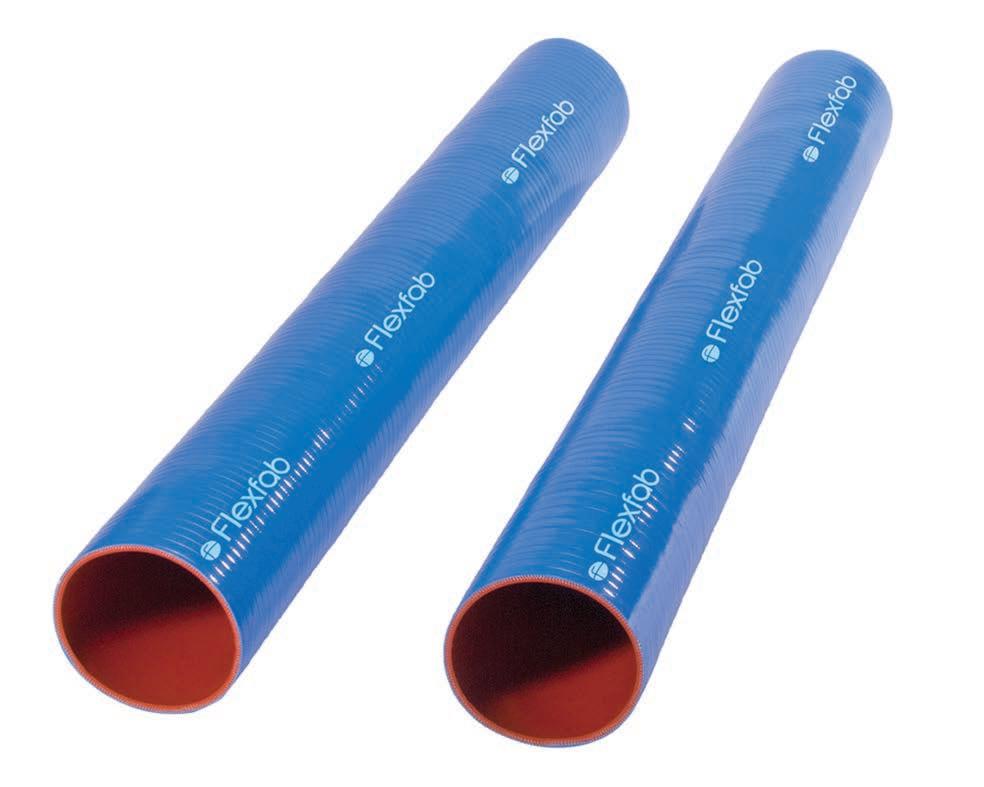
5515 AND
5500 SERIES: 3-PLY COOLANT HOSE To order (3 foot stick) reference part number: FLX5515-300 To order (12 foot stick) reference part number: FLX5515-300x12
Engineered for hostile engine environments, this coolant hose is ideal for extreme temperature and pressure ranges where high performance levels are required. It resists hardening, cracking, cold leaks, aging, and a number of chemicals, making it a durable, long-lasting solution for your applications.
CONSTRUCTION: + Silicone hose with 3-plies of polyester reinforcement
BENEFITS Extreme Temperature Resistance Extreme Duty Cycle Tested for Hostile Engine Environments Durable Construction for Various Pressure Ranges Long Life Design
+ Available in: + Stocked in 3’ lengths + 12’ lengths also available (call for availability)
CUSTOM ENGINEERED TO WITHSTAND:
SPECIFICATIONS: + Meets or exceeds the operating requirements of SAE J20 R1 Class A + Meets or exceeds the operating requirements of TMC RP303B Class I Grade II + Custom wall thickness is .140”/.190”
HOT TEMPS
OIL SPLASH RESISTANCE
OZONE RESISTANT
DIRECT SUNLIGHT
TEMPERATURE RANGE: 500
+ Working pressure is 1/3 of the burst pressure + Resists hardening, cracking, cold leaks, aging, and many chemicals + Ideal for extreme temperature and various pressure ranges where high performance levels are required
4
COOL TEMPS
350
350º F (+177º C)
200 50 0 -50 -200
- 65º F (-54º C)
-350 -500
Phone: 888-353-9323 Fax: 888-353-9344 Email: distribution@flexfab.com www.flexfab.com
5515 AND 5500 SERIES: 3-PLY COOLANT HOSE Blue Series Part Number
Green Series Part Number
Inch
MM
Inch
MM
Actual Burst Pressure - PSI
SAE J20 R1
TMC
5515-038 5500-038
0.38
10
0.70
18
500
425
125
0.12
-
5515-050 5500-050
0.50
13
0.82
21
500
425
125
0.16
2582-0006
5515-062 5500-062
0.63
16
0.95
24
485
425
125
0.20
2582-0010
5515-075 5500-075
0.75
19
1.07
27
475
325
125
0.24
2582-0012
5515-087 5500-087
0.88
22
1.20
30
465
300
125
0.28
2582-0012
5515-100 5500-100
1.00
25
1.32
34
450
300
125
0.32
2582-0016
5515-112 5500-112
1.13
29
1.45
37
435
300
125
0.36
2582-0016 or 2584-0175
5515-125 5500-125
1.25
32
1.57
40
425
275
125
0.40
2582-0020 or 2584-0175
5515-138 5500-138
1.38
35
1.70
43
400
250
125
0.44
2582-0020 or 2584-0212
5515-150 5500-150
1.50
38
1.82
46
375
250
125
0.48
2582-0024 or 2584-0212
5515-162 5500-162
1.63
41
1.95
50
350
225
125
0.52
2582-0024 or 2584-0212
5515-175 5500-175
1.75
44
2.07
53
300
225
125
0.56
2582-0028 or 2584-0262
5515-187 5500-187
1.88
48
2.20
56
250
200
100
0.60
2582-0032 or 2584-0262
5515-200 5500-200
2.00
51
2.32
59
250
200
100
0.64
2582-0032 or 2584-0262
5515-212 5500-212
2.13
54
2.45
62
235
175
100
0.68
2582-0032 or 2584-0262
5515-225 5500-225
2.25
57
2.57
65
225
175
100
0.72
2582-0036 or 2584-0312
5515-238 5500-238
2.38
60
2.70
69
210
150
100
0.76
2582-0040 or 2584-0312
5515-250 5500-250
2.50
64
2.82
72
200
150
100
0.80
2582-0040 or 2584-0312
5515-262 5500-262
2.63
67
2.95
75
200
125
100
0.84
2582-0040 or 2584-0312
5515-275 5500-275
2.75
70
3.07
78
200
125
100
0.88
2582-0044 or 2584-0362
5515-287 5500-287
2.88
73
3.20
81
200
100
100
0.92
2582-0044 or 2584-0362
5515-300 5500-300
3.00
76
3.32
84
200
100
100
0.96
2582-0048 or 2584-0362
5515-312 5500-312
3.13
80
3.45
88
175
75
100
1.00
2582-0048 or 2584-0362
5515-325 5500-325
3.25
83
3.57
91
175
75
100
1.04
2582-0052 or 2584-0412
5515-338 5500-338
3.38
86
3.70
94
150
75
100
1.08
2582-0052 or 2584-0412
5515-350 5500-350
3.50
89
3.82
97
150
75
100
1.12
2582-0056 or 2584-0412
5515-375 5500-375
3.75
95
4.07
103
135
50
100
1.20
2582-0060 or 2584-0412
5515-387 5500-387
3.88
99
4.20
107
125
50
100
1.24
2582-0060 or 2584-0462
5515-400 5500-400
4.00
102
4.32
110
125
50
100
1.28
2582-0064 or 2584-0462
5515-450 5500-450
4.50
114
4.82
122
100
N/A
N/A
1.44
2582-0072 or 2584-0512
5515-500 5500-500
5.00
127
5.32
135
90
N/A
N/A
1.60
2584-0562
5515-550 5500-550
5.50
140
5.82
148
75
N/A
N/A
1.76
2584-0612
5515-600 5500-600
6.00
152
6.32
161
75
N/A
N/A
1.92
2584-0662
Inside Diameter
Outside Diameter
Burst Pressure - PSI
Weight (LB/FT)
Clamp
*Specifications for reference only. Specific test data available on request.
Flexfab GR 4440 44th St. SE, Kentwood, MI 49512, USA
5
5581 AND
5501 SERIES:
4-PLY COOLANT HOSE To order (3 foot stick) reference part number: FLX5581-300 To order (12 foot stick) reference part number: FLX5581-300x12
Put this 4-ply silicone polyester coolant hose to work in your extreme temperature and pressure range environments. You’ll find its reliable construction resists many of the issues other hoses present, including hardening, cracking, and aging. Ideal for diesel powered city transit, school buses, and refuse vehicles.
BENEFITS Extreme Temperature Resistance Extreme Duty Cycle Tested for Hostile Engine Environments Durable Construction for Various Pressure Ranges Long Life Design
CONSTRUCTION: + Silicone hose with 4-plies of polyester reinforcement + Available in:
CUSTOM ENGINEERED TO WITHSTAND:
+ Stocked in 3’ lengths + 12’ lengths also available (call for availability)
SPECIFICATIONS:
COOL TEMPS
+ Meets or exceeds the operating requirements of SAE J20 R1 Class A + Meets or exceeds the operating requirements of TMC RP303B Class I Grade II + Standard wall thickness is .170”/.220” + Resists hardening, cracking, cold leaks, aging, and many chemicals + Ideal for extreme temperature and various pressure ranges where high performance levels are required
OIL SPLASH RESISTANCE
OZONE RESISTANT
DIRECT SUNLIGHT
TEMPERATURE RANGE: 500 350
+ Working pressure is 1/3 of the burst pressure
HOT TEMPS
350º F (+177º C)
200 50 0 -50 -200
- 65º F (-54º C)
-350 -500
+ Ideal for diesel powered city transit, school buses, and refuse vehicles
6
Phone: 888-353-9323 Fax: 888-353-9344 Email: distribution@flexfab.com www.flexfab.com
5581 AND 5501 SERIES: 4-PLY COOLANT HOSE Blue Series Part Number
Green Series Part Number
Inch
MM
Inch
MM
Actual Burst Pressure - PSI
SAE J20 R1
TMC
5581-038 5501-038
0.38
10
0.77
20
600
425
5581-050 5501-050
0.50
13
0.89
23
600
425
5581-062 5501-062
0.63
16
1.02
26
585
5581-075 5501-075
0.75
19
1.14
29
5581-087 5501-087
0.88
22
1.27
5581-100 5501-100
1.00
25
1.39
5581-112 5501-112
1.13
29
5581-125 5501-125
1.25
32
5581-138 5501-138
1.38
5581-150 5501-150
Weight (LB/FT)
Clamp
125
0.16
2582-0006
125
0.20
2582-0008
425
125
0.24
2582-0010
575
325
125
0.29
2582-0012
32
560
300
125
0.34
2582-0016
35
550
300
125
0.39
2582-0016 or 2584-0175
1.52
39
525
300
125
0.44
2582-0020 or 2584-0175
1.64
42
500
275
125
0.49
2582-0020 or 2584-0212
35
1.77
45
475
250
125
0.54
2582-0024 or 2584-0212
1.50
38
1.89
48
450
250
125
0.59
2582-0024 or 2584-0212
5581-162 5501-162
1.63
41
2.02
51
425
225
125
0.63
2582-0028 or 2584-0262
5581-175 5501-175
1.75
44
2.14
54
400
225
125
0.68
2582-0028 or 2584-0262
5581-187 5501-187
1.88
48
2.27
58
400
200
100
0.73
2582-0032 or 2584-0262
5581-200 5501-200
2.00
51
2.39
61
400
200
100
0.78
2582-0032 or 2584-0262
5581-212 5501-212
2.13
54
2.52
64
375
175
100
0.83
2582-0036 or 2584-0312
5581-225 5501-225
2.25
57
2.64
67
350
175
100
0.88
2582-0036 or 2584-0312
5581-238 5501-238
2.38
60
2.77
70
325
150
100
0.93
2582-0040 or 2584-0312
5581-250 5501-250
2.50
64
2.89
73
300
150
100
0.98
2582-0040 or 2584-0312
5581-262 5501-262
2.63
67
3.02
77
285
125
100
1.02
2582-0044 or 2584-0362
5581-275 5501-275
2.75
70
3.14
80
275
125
100
1.07
2582-0044 or 2584-0362
5581-287 5501-287
2.88
73
3.27
83
250
100
100
1.12
2582-0048 or 2584-0362
5581-300 5501-300
3.00
76
3.39
86
250
100
100
1.17
2582-0048 or 2584-0362
5581-312 5501-312
3.13
80
3.52
89
225
75
100
1.22
2582-0052 or 2584-0412
5581-325 5501-325
3.25
83
3.64
92
225
75
100
1.27
2582-0052 or 2584-0412
5581-338 5501-338
3.38
86
3.77
96
200
75
100
1.32
2582-0056 or 2584-0412
5581-350 5501-350
3.50
89
3.89
99
200
75
100
1.37
2582-0056 or 2584-0412
5581-375 5501-375
3.75
95
4.14
105
175
50
100
1.46
2582-0060 or 2584-0462
5581-400 5501-400
4.00
102
4.39
112
150
50
100
1.56
2582-0064 or 2584-0462
5581-450 5501-450
4.50
114
4.89
124
150
N/A
N/A
1.76
2582-0072 or 2584-0512
5581-500 5501-500
5.00
127
5.39
137
125
N/A
N/A
1.95
2584-0562
5581-550 5501-550
5.50
140
5.89
150
100
N/A
N/A
2.16
2584-0612
5581-600 5501-600
6.00
152
6.39
162
100
N/A
N/A
2.34
2584-0662
Inside Diameter
Outside Diameter
Burst Pressure - PSI
*Specifications for reference only. Specific test data available on request.
Flexfab GR 4440 44th St. SE, Kentwood, MI 49512, USA
7
5415 SERIES: 3-PLY GLOSSY COOLANT HOSE Ideal for high-performance environments where oil splash is present, Flexfab’s 3-ply glossy lined polyester coolant hose stands out for its strength and durability. It won’t harden, crack, or leak, and resists aging, a range of chemicals, ozone, and UV rays.
CONSTRUCTION: + Silicone hose with 3-plies of polyester reinforcement + Available in: + Stocked in 3’ lengths
SPECIFICATIONS:
BENEFITS Extreme Temperature Resistance Extreme Duty Cycle Tested for Hostile Engine Environments Durable Construction for Various Pressure Ranges Glossy Exterior Ideal Where Oil Splash is Present CUSTOM ENGINEERED TO WITHSTAND:
+ Meets or exceeds the operating requirements of SAE J20 R1 Class A + Meets or exceeds the operating requirements of TMC RP303B Class I Grade II
COOL TEMPS
HOT TEMPS
OIL SPLASH RESISTANCE
OZONE RESISTANT
DIRECT SUNLIGHT
+ Standard wall thickness is .140”/.190” + Working pressure is 1/3 of the burst pressure + Resists hardening, cracking, cold leaks, aging, and many chemicals + Ideal for extreme temperature and various pressure ranges where high performance levels are required
TEMPERATURE RANGE: 500 350
350º F (+177º C)
200 50 0 -50 -200
- 65º F (-54º C)
-350 -500
8
Phone: 888-353-9323 Fax: 888-353-9344 Email: distribution@flexfab.com www.flexfab.com
5415 SERIES: 3-PLY GLOSSY COOLANT HOSE Inch
MM
Inch
MM
Actual Burst Pressure - PSI
5415-038
0.38
10
0.70
18
500
425
125
0.12
-
5415-050
0.50
13
0.82
21
500
425
125
0.16
2582-0006
5415-062
0.63
16
0.95
24
485
425
125
0.20
2582-0010
5415-075
0.75
19
1.07
27
475
325
125
0.24
2582-0012
5415-087
0.88
22
1.20
30
465
300
125
0.28
2582-0012
5415-100
1.00
25
1.32
34
450
300
125
0.32
2582-0016
5415-112
1.13
29
1.45
37
435
300
125
0.36
2582-0016 or 2584-0175
5415-125
1.25
32
1.57
40
425
275
125
0.40
2582-0020 or 2584-0175
5415-138
1.38
35
1.70
43
400
250
125
0.44
2582-0020 or 2584-0212
5415-150
1.50
38
1.82
46
375
250
125
0.48
2582-0024 or 2584-0212
5415-162
1.63
41
1.95
50
350
225
125
0.52
2582-0024 or 2584-0212
5415-175
1.75
44
2.07
53
300
225
125
0.56
2582-0028 or 2584-0262
5415-187
1.88
48
2.20
56
250
200
100
0.60
2582-0032 or 2584-0262
5415-200
2.00
51
2.32
59
250
200
100
0.64
2582-0032 or 2584-0262
5415-212
2.13
54
2.45
62
235
175
100
0.68
2582-0032 or 2584-0262
5415-225
2.25
57
2.57
65
225
175
100
0.72
2582-0036 or 2584-0312
5415-238
2.38
60
2.70
69
210
150
100
0.76
2582-0040 or 2584-0312
5415-250
2.50
64
2.82
72
200
150
100
0.80
2582-0040 or 2584-0312
5415-262
2.63
67
2.95
75
200
125
100
0.84
2582-0040 or 2584-0312
5415-275
2.75
70
3.07
78
200
125
100
0.88
2582-0044 or 2584-0362
5415-287
2.88
73
3.20
81
200
100
100
0.92
2582-0044 or 2584-0362
5415-300
3.00
76
3.32
84
200
100
100
0.96
2582-0048 or 2584-0362
5415-312
3.13
80
3.45
88
175
75
100
1.00
2582-0048 or 2584-0362
5415-325
3.25
83
3.57
91
175
75
100
1.04
2582-0052 or 2584-0412
5415-338
3.38
86
3.70
94
150
75
100
1.08
2582-0052 or 2584-0412
5415-350
3.50
89
3.82
97
150
75
100
1.12
2582-0056 or 2584-0412
5415-375
3.75
95
4.07
103
135
50
100
1.20
2582-0060 or 2584-0412
5415-387
3.88
99
4.20
107
125
50
100
1.24
2582-0060 or 2584-0462
5415-400
4.00
102
4.32
110
125
50
100
1.28
2582-0064 or 2584-0462
5415-450
4.50
114
4.82
122
100
N/A
N/A
1.44
2582-0072 or 2584-0512
5415-500
5.00
127
5.32
135
90
N/A
N/A
1.60
2584-0562
5415-550
5.50
140
5.82
148
75
N/A
N/A
1.76
2584-0612
5415-600
6.00
152
6.32
161
75
N/A
N/A
1.92
2584-0662
Part Number
Inside Diameter
Outside Diameter
Burst Pressure - PSI SAE J20 R1
TMC
Weight (LB/FT)
Clamp
*Specifications for reference only. Specific test data available on request.
Flexfab GR 4440 44th St. SE, Kentwood, MI 49512, USA
9
5508 SERIES: WIRE REINFORCED COOLANT HOSE This coolant hose is reinforced with two plies of polyester reinforcement, with helical wire that allows for some forced curvature. This design makes it an ideal solution for heavy duty pressure connections in hostile engine environments.
CONSTRUCTION: + Silicone hose with 2-plies of polyester reinforcement, with helical wire + Available in: + Stocked in 3’ lengths + 12’ lengths also available (call for availability)
BENEFITS Extreme Temperature Resistance Helical Wire Construction Withstand Vacuum Pressures Extreme Duty Cycle Tested for Hostile Engine Environments Engineered for Heavy Duty Pressure Connections Wire Reinforced Coolant Hoses are Designed to Handle Vacuum and/or Some Forced Curvature
SPECIFICATIONS: + Meets or exceeds the operating requirements of SAE J20 R2 Class A
CUSTOM ENGINEERED TO WITHSTAND:
+ Wall thickness at Hose ends exclusive of Wire Gauge .130”/.180” + Working pressure is 1/3 of the burst pressure + Negative pressure is -10 PSI
COOL TEMPS
HOT TEMPS
OIL SPLASH RESISTANCE
OZONE RESISTANT
DIRECT SUNLIGHT
TEMPERATURE RANGE: 500 350
350º F (+177º C)
200 50 0 -50 -200
- 65º F (-54º C)
-350 -500
10
Phone: 888-353-9323 Fax: 888-353-9344 Email: distribution@flexfab.com www.flexfab.com
5508 SERIES: WIRE REINFORCED COOLANT HOSE Part Number
Inside Diameter
Outside Diameter
Burst Pressure PSI
Max Neg. PSI
Bend Radius (Inch)
Weight (LB/FT)
MM
Inch
MM
0.50
13
0.92
23
600
10
2.00
0.17
5508-062
0.63
16
1.05
27
600
10
2.25
0.21
5508-075
0.75
19
1.17
30
600
10
2.50
0.23
5508-087
0.88
22
1.30
33
550
10
2.75
0.26
5508-100
1.00
25
1.42
36
550
10
3.00
0.30
5508-125
1.25
32
1.67
42
525
10
3.50
0.36
5508-150
1.50
38
1.92
49
500
10
4.00
0.43
5508-175
1.75
44
2.17
55
475
10
4.50
0.51
5508-200
2.00
51
2.42
61
450
10
5.00
0.56
5508-225
2.25
57
2.67
68
400
10
5.50
0.65
5508-250
2.50
64
2.92
74
350
10
6.00
0.74
5508-275
2.75
70
3.17
81
325
10
6.50
0.79
5508-300
3.00
76
3.42
87
300
10
7.00
0.85
5508-350
3.50
89
3.92
100
275
10
8.00
1.09
5508-400
4.00
102
4.42
112
250
10
9.00
1.19
5508-600
6.00
152
6.42
163
125
10
13.00
1.84
Inch
5508-050
*Specifications for reference only. Specific test data available on request.
Flexfab GR 4440 44th St. SE, Kentwood, MI 49512, USA
11
3000 SERIES: COOLANT HOSE KITS
At 1’ length, Flexfab’s 3000 series coolant hose and clamp kits are convenient for on the go use. Engineered for hostile engine environments, this coolant hose is ideal for extreme temperature and pressure ranges where high performance levels are required. Silicone resists hardening, cracking, cold leaks, aging, and a number of chemicals, making it a durable, long-lasting solution for your applications.
BENEFITS Extreme Temperature Resistance Extreme Duty Cycle Tested for Hostile Engine Environments Durable Construction for Various Pressure Ranges Long Life Design
CONSTRUCTION: + Silicone hose with 3 plies of polyester reinforcement + Available in:
CUSTOM ENGINEERED TO WITHSTAND:
+ Stocked in 1’ lengths COOL TEMPS
SPECIFICATIONS: + Meets or exceeds the operating requirements of SAE J20 R1 Class A + Meets or exceeds the operating requirements of TMC RP303B Class I Grade II + Custom wall thickness is .140”/.190” + Working pressure is 1/3 of the burst pressure + Resists hardening, cracking, cold leaks, aging, and many chemicals + Ideal for extreme temperature and various pressure ranges where high performance levels are required
12
HOT TEMPS
OIL SPLASH RESISTANCE
OZONE RESISTANT
DIRECT SUNLIGHT
TEMPERATURE RANGE: 500 350
350º F (+177º C)
200 50 0 -50 -200
- 65º F (-54º C)
-350 -500
Phone: 888-353-9323 Fax: 888-353-9344 Email: distribution@flexfab.com www.flexfab.com
3000 SERIES: COOLANT HOSE KITS Part Number KIT3001 KIT3002 KIT3003 KIT3004
Hose and Clamp Provided in Kit
Hose Length Inch
Inside Diameter Inch MM
Outside Diameter Inch MM
Actual Burs Pressure PSI
Burst Pressure PSI SAE J20 R1 TMC
Weight (LB)
5515-200
12
2
51
2.32
59
250
200
100
2584-0262
N/A
1.75 - 2.63
45 - 67
N/A
N/A
N/A
N/A
N/A
0.2
5515-225
12
2.25
57
2.57
65
225
175
100
0.72
2584-0312
N/A
2.25 - 3.13
57 - 79
N/A
N/A
N/A
N/A
N/A
0.2
5515-250
12
2.5
64
2.82
72
200
150
100
0.8
2584-0312
N/A
2.25 - 3.13
57 - 79
N/A
N/A
N/A
N/A
N/A
0.2
5515-300
12
3
76
3.32
84
200
100
100
0.96
2584-0362
N/A
2.75 - 3.63
70 - 92
N/A
N/A
N/A
N/A
N/A
0.2
Flexfab GR 4440 44th St. SE, Kentwood, MI 49512, USA
0.64
13
HIGH TEMP COOLANT HOSE Our high temperature coolant hose features a thicker wall that offers higher pressure handling than standard hoses. Strong and reliable, it withstands the hardening, cracking, and leaks that can be present in hostile engine environments. Plus, it’s resistant to aging and chemicals, including coolant additives.
BENEFITS Extreme Temperature Resistance Extreme Duty Cycle Tested for Hostile Engine Environments Pressure Endurance Available in Various Lengths
CONSTRUCTION: + Silicone + Meta-Aramid
CUSTOM ENGINEERED TO WITHSTAND:
+ Available in various standard lengths*
SPECIFICATIONS:
COOL TEMPS
+ Meets or exceeds SAE J20 R1 H.T. + Standard wall thickness available in 3/8” - 2 1/2” diameter + Heavy wall thickness available in 2 5/8” - 6” diameter + Extreme pressure resistance up to 175 PSIG
HOT TEMPS
OIL SPLASH RESISTANCE
OZONE RESISTANT
DIRECT SUNLIGHT
TEMPERATURE RANGE: 500 350
500º F (+260º C)
200 50 0 -50 -200
- 65º F (-54º C)
-350 -500
14
Phone: 888-353-9323 Fax: 888-353-9344 Email: distribution@flexfab.com www.flexfab.com
HIGH TEMP COOLANT HOSE: Part Number
Wall Thickness
Inside Diameter
Outside Diameter
Pressure Ratings
Min
Max
Inch
MM
Inch
MM
Working (PSI)
Burst (PSI)
5780-038
0.170
0.220
0.38
10
0.77
20
175
600
5780-050
0.170
0.220
0.50
13
0.89
23
175
600
5780-062
0.170
0.220
0.63
16
1.02
26
175
575
5780-075
0.170
0.220
0.75
19
1.14
29
175
575
5780-087
0.170
0.220
0.88
22
1.27
32
150
550
5780-100
0.170
0.220
1.00
25
1.39
35
150
550
5780-112
0.170
0.220
1.13
29
1.52
39
150
500
5780-125
0.170
0.220
1.25
32
1.64
42
150
500
5780-138
0.170
0.220
1.38
35
1.77
45
150
450
5780-150
0.170
0.220
1.50
38
. 1.89.
48
150
450
5780-162
0.170
0.220
1.62
41
2.01
51
125
400
5780-175
0.170
0.220
1.75
44
2.14
54
125
400
5780-187
0.170
0.220
1.88
48
2.27
58
125
400
5780-200
0.170
0.220
2.00
51
2.39
61
125
400
5780-212
0.170
0.220
2.13
54
2.52
64
100
350
5780-225
0.170
0.220
2.25
57
2.64
67
100
350
5780-238
0.170
0.220
2.38
60
2.77
70
100
300
5780-250
0.170
0.220
2.50
64
2.89
73
100
300
5780-262
0.220
0.279
2.63
67
3.13
79
80
275
5780-275
0.220
0.279
2.75
70
3.25
83
80
275
5780-287
0.220
0.279
2.88
73
3.38
86
80
250
5780-300
0.220
0.279
3.00
76
3.50
89
80
250
5780-312
0.220
0.279
3.13
80
3.63
92
60
200
5780-325
0.220
0.279
3.25
83
3.75
95
60
200
5780-338
0.220
0.279
3.38
86
3.88
99
60
200
5780-350
0.220
0.279
3.50
89
4.00
102
60
200
5780-375
0.220
0.279
3.75
95
4.25
108
50
150
5780-400
0.220
0.279
4.00
102
4.50
114
50
150
5780-450
0.220
0.279
4.50
114
5.00
127
40
120
5780-500
0.220
0.279
5.00
127
5.50
140
35
105
5780-550
0.220
0.279
5.50
140
6.00
152
30
100
5780-600
0.220
0.279
6.00
152
6.50
165
30
100
Flexfab GR 4440 44th St. SE, Kentwood, MI 49512, USA
15
5526 SERIES: STANDARD HEATER HOSE Engineered with superior flexibility and durability, Flexfab’s standard heater hose is resistant to coolant additives, as well as hardening, cracking, cold leaks, and aging. It’s extreme duty cycle tested.
BENEFITS Box and Spool Lengths Available Extreme Temperature Resistance Superior Flexibility
CONSTRUCTION: + Silicone hose with 1-ply of nylon fiber reinforcement + Available in:
Extreme Duty Cycle Tested for Hostile Engine Environments Durable Construction
+ Stocked in 25’ and 50’ boxes + Available in longer lengths on standard wooden spools* *Continuous lengths are not guaranteed, if continuous lengths are required please contact a sales rep for price and availability
Resistant to Coolant Additives CUSTOM ENGINEERED TO WITHSTAND:
SPECIFICATIONS: + Meets or exceeds the operating requirements of SAE J20 R3 Class A + Meets or exceeds the operating requirements of TMC RP303B Class I Grade II + Standard wall thickness is .140”/.170”
COOL TEMPS
OIL SPLASH RESISTANCE
OZONE RESISTANT
DIRECT SUNLIGHT
TEMPERATURE RANGE: 500
+ Working pressure is 1/3 of the burst pressure
350
+ Bend radius is 5 times the ID of the hose
50
+ Resists hardening, cracking, cold leaks, aging, and many chemicals
16
HOT TEMPS
350º F (+177º C)
200
0 -50 -200
- 65º F (-54º C)
-350 -500
Phone: 888-353-9323 Fax: 888-353-9344 Email: distribution@flexfab.com www.flexfab.com
5526 SERIES: STANDARD HEATER HOSE Part Number
Inside Diameter
Outside Diameter
Actual Burst Pressure - PSI
Burst Pressure - PSI
Weight (LB/FT)
Overall Length (Feet) 25’ Box
Clamp
Inch
MM
Inch
MM
SAE J20 R1
TMC
5526-025x25
0.25
6
0.58
15
320
250
125
0.111
5526-025x50
0.25
6
0.58
15
320
250
125
0.111
50’ Box
-
5526-025x250
0.25
6
0.58
15
320
250
125
0.111
250’ Spool
-
5526-025x800
0.25
6
0.58
15
320
250
125
0.111
800’ Spool
-
5526-031x25
0.31
8
0.64
16
310
250
125
0.128
25’ Box
-
5526-031x50
0.31
8
0.64
16
310
250
125
0.128
50’ Box
-
5526-031x600
0.31
8
0.64
16
310
250
125
0.128
600’ Spool
-
5526-038x25
0.38
10
0.71
18
310
250
125
0.145
25’ Box
2582-0006
5526-038x50
0.38
10
0.71
18
310
250
125
0.145
50’ Box
2582-0006
5526-038x250
0.38
10
0.71
18
310
250
125
0.145
250’ Spool
2582-0006
5526-038x600
0.38
10
0.71
18
310
250
125
0.145
600’ Spool
2582-0006
5526-050x25
0.50
13
0.83
21
310
250
125
0.181
25’ Box
2582-0006
5526-050x50
0.50
13
0.83
21
310
250
125
0.181
50’ Box
2582-0006
5526-050x250
0.50
13
0.83
21
310
250
125
0.181
250’ Spool
2582-0006
5526-050x500
0.50
13
0.83
21
310
250
125
0.181
500’ Spool
2582-0006
5526-062x25
0.63
16
0.96
24
300
250
125
0.216
25’ Box
2582-0008
5526-062x50
0.63
16
0.96
24
300
250
125
0.216
50’ Box
2582-0008
5526-062x250
0.63
16
0.96
24
300
250
125
0.216
250’ Spool
2582-0008
5526-062x400
0.63
16
0.96
24
300
250
125
0.216
400’ Spool
2582-0008
5526-075x25
0.75
19
1.08
27
300
200
125
0.25
25’ Box
2582-0010
5526-075x50
0.75
19
1.08
27
300
200
125
0.25
50’ Box
2582-0010
5526-075x250
0.75
19
1.08
27
300
200
125
0.25
250’ Spool
2582-0010
5526-075x300
0.75
19
1.08
27
300
200
125
0.25
300’ Spool
2582-0010
5526-087x25
0.88
22
1.21
31
250
175
125
0.287
25’ Box
2582-0012
5526-087x50
0.88
22
1.21
31
250
175
125
0.287
50’ Box
2582-0012
5526-087x200
0.88
22
1.21
31
250
175
125
0.287
200’ Spool
2582-0012
5526-100x25
1.00
25
1.33
34
250
175
125
0.324
25’ Box
2582-0016
5526-100x50
1.00
25
1.33
34
250
175
125
0.324
50’ Box
2582-0016
5526-100x200
1.00
25
1.33
34
250
175
125
0.324
200’ Spool
2582-0016
5526-125x25
1.25
32
1.58
40
200
175
125
0.385
25’ Box
2582-0020
5526-125x50
1.25
32
1.58
40
200
175
125
0.385
50’ Box
2582-0020
5526-125x150
1.25
32
1.58
40
200
175
125
0.385
150’ Spool
2582-0020
*Specifications for reference only. Specific test data available on request.
Flexfab GR 4440 44th St. SE, Kentwood, MI 49512, USA
17
5521 AND
5834 SERIES:
PREMIUM HEATER HOSE Our premium heater hose features a thicker wall that offers higher pressure handling than standard hoses. Strong and reliable, it withstands the hardening, cracking, and leaks that can be present in hostile engine environments. Plus, it’s resistant to aging and chemicals, including coolant additives.
BENEFITS Box and Spool Lengths* Extreme Temperature Resistance Extreme Duty Cycle Tested for Hostile Engine Environments Superior Flexibility
CONSTRUCTION: + 5521 Series: silicone hose with 1-ply of nylon fiber reinforcement. Green cover, red liner
Bend Radius is 5 x ID Durable Construction Resistant to Coolant Additives
+ 5834 Series: silicone hose with 1-ply of para-aramid fiber reinforcement. Blue cover, red liner
Pressure Endurance
+ Available in:
+ Available in: + Stocked in 25’ and 50’ boxes + Available in longer lengths on standard wooden spools*
Thicker Wall Offers Higher Pressure Handling CUSTOM ENGINEERED TO WITHSTAND:
*Continuous lengths are not guaranteed, if continuous lengths are required please contact a sales rep for price and availability COOL TEMPS
SPECIFICATIONS: + Meets or exceeds the operating requirements of SAE J20 R3 Class A + Meets or exceeds the operating requirements of TMC RP303B Class I Grade II + Standard wall thickness is .170”/.220” + Working pressure is 1/3 of the burst pressure + Resists hardening, cracking, cold leaks, aging, and many chemicals 18
HOT TEMPS
OIL SPLASH RESISTANCE
OZONE RESISTANT
DIRECT SUNLIGHT
TEMPERATURE RANGE: 500 350
350º F (+177º C)
200 50 0 -50 -200
- 65º F (-54º C)
-350 -500
Phone: 888-353-9323 Fax: 888-353-9344 Email: distribution@flexfab.com www.flexfab.com
5521 SERIES: PREMIUM HEATER HOSE (GREEN) Part Number
Inside Diameter
Actual Burst Pressure - PSI
Outside Diameter
Inch
MM
Inch
MM
5521-025x25
0.25
6
0.64
16
5521-025x50
0.25
6
0.64
16
5521-025x800
0.25
6
0.64
16
475
5521-031x25
0.31
8
0.70
18
475
5521-031x50
0.31
8
0.70
18
475
5521-031x600
0.31
8
0.70
18
475
5521-038x25
0.38
10
0.77
20
5521-038x50
0.38
10
0.77
20
5521-038x500
0.38
10
0.77
5521-050x25
0.50
13
5521-050x50
0.50
13
5521-050x500
0.50
5521-062x25
Burst Pressure - PSI
Weight (LB/FT)
Overall Length (Feet)
Clamp
SAE J20 R1
TMC
475
475
125
0.121
25’ Box
-
475
475
125
0.121
50’ Box
-
475
125
0.121
800’ Spool
-
475
125
0.151
25’ Box
-
475
125
0.151
50’ Box
-
475
125
0.151
500’ Spool
-
475
475
125
0.181
25’ Box
2582-0006
475
475
125
0.181
50’ Box
2582-0006
20
475
475
125
0.181
600’ Spool
2582-0006
0.89
23
425
425
125
0.226
25’ Box
2582-0006
0.89
23
425
425
125
0.226
50’ Box
2582-0006
13
0.89
23
425
425
125
0.226
500’ Spool
2582-0006
0.63
16
1.02
26
375
375
125
0.258
25’ Box
2582-0010
5521-062x50
0.63
16
1.02
26
375
375
125
0.258
50’ Box
2582-0010
5521-062x400
0.63
16
1.02
26
375
375
125
0.258
400’ Spool
2582-0010
5521-075x25
0.75
19
1.14
29
325
325
125
0.301
25’ Box
2582-0012
5521-075x50
0.75
19
1.14
29
325
325
125
0.301
50’ Box
2582-0012
5521-075x300
0.75
19
1.14
29
325
325
125
0.301
300’ Spool
2582-0012
5521-087x25
0.88
22
1.27
32
300
300
125
0.346
25’ Box
2582-0012
5521-087x50
0.88
22
1.27
32
300
300
125
0.346
50’ Box
2582-0012
5521-087x200
0.88
22
1.27
32
300
300
125
0.346
150’ Spool
2582-0012
5521-100x25
1.00
25
1.39
35
300
300
125
0.391
25’ Box
2582-0016
5521-100x50
1.00
25
1.39
35
300
300
125
0.391
50’ Box
2582-0016
5521-100x200
1.00
25
1.39
35
300
300
125
0.391
200’ Spool
2582-0016
5521-125x25
1.25
32
1.64
42
200
275
125
0.491
25’ Box
2582-0020
5521-125x50
1.25
32
1.64
42
200
275
125
0.491
50’ Box
2582-0020
5521-125x150
1.25
32
1.64
42
200
275
125
0.491
150’ Spool
2582-0020
*Specifications for reference only. Specific test data available on request.
5834 SERIES: PREMIUM HEATER HOSE (BLUE) Part Number
Inside Diameter
Outside Diameter
Inch
MM
Inch
MM
5834-112x25
1.13
29
1.52
38
5834-112x50
1.13
29
1.52
38
5834-112x150
1.13
29
1.52
38
Actual Burst Pressure - PSI
Burst Pressure - PSI
Weight (LB/FT)
Overall Length (Feet)
Clamp
SAE J20 R1
TMC
250
275
125
0.438
25’ Box
2582-0020
250
275
125
0.438
50’ Box
2582-0020
250
275
125
0.438
150’ Spool
2582-0020
*Specifications for reference only. Specific test data available on request.
Flexfab GR 4440 44th St. SE, Kentwood, MI 49512, USA
19
SPECIALTY HOSES:
A.
b.
B.
C.
D.
Designed for unique applications, Flexfab’s specialty hoses are durable, long lasting, and built to withstand extreme temperature environments. Their maximum operating pressure ranges from 30 PSI for the coolant sleeve to 55 PSI for the charge air 45° elbow.
A. 7730-0001: Coolant Sleeve + Specially designed coolant hose for unique applications. Sales should be consulted before use in new applications as pressure ratings are very specific. + Hose can also be used for a cold side charge air-cooler application
CUSTOM ENGINEERED TO WITHSTAND:
COOL TEMPS
HOT TEMPS
OIL SPLASH RESISTANCE
OZONE RESISTANT
DIRECT SUNLIGHT
+ 4-ply polyester reinforced hose + Maximum operating pressure is 30 PSI + Temperature range is -65°F (-54°C) to +350°F (+177°C)
B. 7967: Coolant Bellows + Meets or exceeds the operating requirements of SAE J20 R1 Class A
CUSTOM ENGINEERED TO WITHSTAND:
+ Once installed, the hose can handle up to 1.00” of lateral movement in the application + 3-Ply Polyester reinforced hose
COOL TEMPS
HOT TEMPS
OIL SPLASH RESISTANCE
OZONE RESISTANT
DIRECT SUNLIGHT
+ Maximum operating pressure is 50 PSI + Temperature range is -65°F (-54°C) to +350°F (+177°C)
20
Phone: 888-353-9323 Fax: 888-353-9344 Email: distribution@flexfab.com www.flexfab.com
C. 7965: Coolant Elbow
CUSTOM ENGINEERED TO WITHSTAND:
+ Meets or exceeds the operating requirements of SAE J20 R1 Class A + Used for a 90˚ coolant connection between pipes
COOL TEMPS
HOT TEMPS
+ Tighter bend radius than most other 90˚ elbows
OIL SPLASH RESISTANCE
OZONE RESISTANT
DIRECT SUNLIGHT
+ 4-ply polyester reinforced hose + Maximum operating pressure is 50 PSI + Temperature range is -65°F (-54°C) to +350°F (+177°C)
D. 7902: Charge Air 45˚ Elbow
CUSTOM ENGINEERED TO WITHSTAND:
+ Used for a 45˚ hot side charge air connection between pipes + 6-ply meta-aramid reinforced hose
COOL TEMPS
HOT TEMPS
+ Maximum operating pressure is 55 PSI
OIL SPLASH RESISTANCE
OZONE RESISTANT
DIRECT SUNLIGHT
+ Temperature range is - 65°F (54°C) to +450°F (+232°C)
SPECIALTY HOSES: Part Number
Inside Diameter
Outside Diameter
Overall Length Inches
Inch
MM
Inch
MM
A. 7730-0001
3.00
76
3.23
82
6.00
B. 7967
2.50
64
2.82
72
8.50
C. 7965
2.50
64
2.92
74
10.00
D. 7902
3.50/4.00
89/102
4.17/4.67
8.75
106/119
Stainless Steel Rings
Burst Pressure - PSI
Weight LBS
Clamp
No
90
0.5
2582-0043 or 2584-0362
Yes
150
0.5
2582-0040 or 2584-0312
No
150
0.5
2582-0040 or 2584-0312
No
165
0.5
2583-0350/2583-0400
*Specifications for reference only. Specific test data available on request.
Flexfab GR 4440 44th St. SE, Kentwood, MI 49512, USA
21
5001 SERIES: HEATER HOSE REPAIR KIT
Reduce engine downtime and make quick repairs on the road with this heater hose repair kit. The kit contains 300-grade stainless steel lined worm gear clamps, 5/16” clamp head, and 9/16” clamp band.
BENEFITS Quick Repairs on the Road -Reduce Engine Downtime Lasts Until Next Service
CONSTRUCTION:
+ Anodized aluminum construction -Corrosion resistance
SPECIFICATIONS: + Bead height per AS5131 specification + Meets anodized aluminum specification MIL-A8625 + 300 grade stainless steel lined worm gear clamps + Clamp hex head 5/16” + Clamp band width 9/16”
22
Phone: 888-353-9323 Fax: 888-353-9344 Email: distribution@flexfab.com www.flexfab.com
5001 SERIES: HEATER HOSE REPAIR KIT
N/A 19
N/A
N/A
1.00
25
FLX2582-‐0016
N/A
N/A
KIT5003D
FLX2582-0010 DEA-36519-1000
5526-062
N/A .047-.087 N/A .047-.087 N/A
N/A 0.75
3.00 N/A
-
3.00
5526-‐075
FLX2582-0008 DEA-36519-0750
.047-.087
N/A
-
3.00
5526-‐100
N/A
-
16
Use With
0.63
Overall Length (Feet)
DEA-36519-0625
Bead Height (AS5131)
MM
Inch
KIT5002D
Outside Diameter
Provided in Kit
KIT5001D
Connector and Clamp
Part Number
*Specifications for reference only.
Flexfab GR 4440 44th St. SE, Kentwood, MI 49512, USA
23
CHARGE AIR
CONNECTOR (CAC) CONVOLUTED REDUCERS Get great value with Flexfab’s charge air convoluted (CAC) reducers. They can be used on both hot side and cold side of the CAC system and are constructed with 4-ply silicone coated meta-aramid fabric. Custom engineered to withstand harsh environments, they are resistant to extreme temperatures and pressures.
BENEFITS Can be Used on Both Hot Side and Cold Side of the CAC System Extreme Temperature Resistance Extreme Duty Cycle Tested for Hostile Engine Environments High Pressure Resistance
CONSTRUCTION: + 4-ply silicone coated meta-aramid fabric with stainless steel pressure retention rings where noted
CUSTOM ENGINEERED TO WITHSTAND:
SPECIFICATIONS: + Wall thickness is .092”/.132” COOL TEMPS
HOT TEMPS
OIL SPLASH RESISTANCE
OZONE RESISTANT
DIRECT SUNLIGHT
TEMPERATURE RANGE: 500 350
500º F (+260º C)
200 50 0 -50 -200
- 65º F (-54º C)
-350 -500
24
Phone: 888-353-9323 Fax: 888-353-9344 Email: distribution@flexfab.com www.flexfab.com
CHARGE AIR CONNECTOR (CAC) CONVOLUTED REDUCERS Inch
MM
Inch
MM
Overall Length Inches
7868
2.50/3.00
64/76
2.73/3.23
69/82
4.00
1
None
40
0.5
7726
3.00/3.50
76/89
3.23/3.73
82/95
5.00
1
2
55
0.5
7766
3.00/4.00
76/102
3.23/4.23
82/107
6.30
1
2
50
0.5
7880
3.50/4.00
89/102
3.73/4.23
95/107
6.00
2
2
50
0.5
7711
4.00/4.50
102/114
4.23/4.73
107/120
6.00
1
None
30
0.5
7866
4.00/4.50
102/114
4.23/4.73
107/120
7.00
2
3
45
0.6
Part Number
Inside Diameter
Outside Diameter
Convolutes (Humps)
Stainless Steel Rings
Max Operating Pressure - PSI
Weight LBS
Clamp 2583-0250/2583-0300 2584-0312/2584-0362 2583-0300/2583-0350 2584-0362/2584-0412 2583-0300/2583-0400 2584-0362/2584-0462 2583-0350/2583-0400 2584-0412/2584-0462 2583-0400/2583-0450 2584-0462/2584-0512 2583-0400/2583-0450 2584-0462/2584-0512
*Specifications for reference only. Specific test data available on request.
Flexfab GR 4440 44th St. SE, Kentwood, MI 49512, USA
25
CHARGE AIR
CONNECTOR (CAC)
HOT SIDE AND COLD SIDE This charge air connector for the hot side features 4-ply silicone coated meta-aramid fabric with stainless steel pressure retention rings. This charge air connector for the cold side features 3-ply silicone coated polyester fabric with stainless steel pressure retention rings.
CONSTRUCTION: + Hot Side: 4-ply silicone coated meta-aramid fabric with stainless steel pressure retention rings + Cold Side: 3-ply silicone coated polyester fabric with stainless steel pressure retention rings
SPECIFICATIONS: + Hot Side: wall thickness is .085”/.135” + Cold Side: wall thickness is .084”/.130”
BENEFITS Extreme Temperature Resistance Extreme Duty Cycle Tested for Hostile Engine Environments High Pressure Resistance CUSTOM ENGINEERED TO WITHSTAND:
COOL TEMPS
HOT TEMPS
OZONE RESISTANT
DIRECT SUNLIGHT
TEMPERATURE RANGE: TEMPERATURE RANGE: HOT SIDE COLD SIDE 500 350
500º F (+260º C)
500 350
200
200
50
50
0 -50 -200 -350 -500
26
OIL SPLASH RESISTANCE
350º F (+177º C)
0
- 65º F (-54º C)
-50 -200 -350
- 65º F (-54º C)
-500
Phone: 888-353-9323 Fax: 888-353-9344 Email: distribution@flexfab.com www.flexfab.com
CHARGE AIR CONNECTOR (CAC) – HOT SIDE Part Number
Inside Diameter
Outside Diameter
Overall Length Inches
Convolutes (Humps)
Stainless Steel Rings
Max Operating Pressure - PSI
Weight LBS
Clamp
Inch
MM
Inch
MM
7887
2.50
64
2.73
69
6.00
2
3
60
0.5
2583-0250 or 2584-0312
7731-0001
3.00
76
3.23
82
6.00
2
3
60
0.5
2583-0300 or 2584-0362
7732-0001
3.50
89
3.73
95
6.00
2
3
55
0.5
2583-0350 or 2584-0412
7717
3.50
89
3.73
95
7.50
2
3
55
0.5
2583-0350 or 2584-0462
7715-0002
4.00
102
4.23
107
6.00
2
3
50
0.5
2583-0400 or 2584-0462
7723
4.00
102
4.23
107
6.00
1
2
50
0.5
2583-0400 or 2584-0462
1020-0001
4.00
102
4.23
107
6.50
2
3
50
0.5
2583-0400 or 2584-0462
7716
4.00
102
4.23
107
7.00
2
3
50
0.6
2583-0400 or 2584-0462
7728
4.00
102
4.23
107
7.50
2
3
50
0.6
2583-0400 or 2584-0462
7727-0001
4.00
102
4.23
107
8.00
2
3
50
0.7
2583-0400 or 2584-0462
7742-0001
4.50
114
4.73
120
6.00
2
3
45
0.5
2583-0450 or 2584-0512
7797
5.00
127
5.23
133
6.00
2
3
35
0.5
2583-0500 or 2584-0562
*Specifications for reference only. Specific test data available on request.
CHARGE AIR CONNECTOR (CAC) – COLD SIDE Part Number
Inside Diameter
Outside Diameter
Overall Length Inches
Convolutes (Humps)
Stainless Steel Rings
Max Operating Pressure - PSI
Weight LBS
Clamp
Inch
MM
Inch
MM
7758-0001
3.00
76
3.23
82
6.00
2
3
60
0.5
2583-0300 or 2584-0362
7753-0001
3.50
89
3.73
95
6.00
2
3
55
0.5
2583-0350 or 2584-0412
7755-0002
4.00
102
4.23
107
6.00
2
3
50
0.5
2583-0400 or 2584-0462
7759-0001
4.50
114
4.73
120
6.00
2
3
45
0.5
2583-0450 or 2584-0512
*Specifications for reference only. Specific test data available on request.
Flexfab GR 4440 44th St. SE, Kentwood, MI 49512, USA
27
HEAVY–WALL CHARGE AIR
CONNECTOR (CAC)
HOT SIDE AND COLD SIDE Exclusive to Flexfab, these heavy-wall charge air connectors feature clamp saddle design for proper clamp alignment, along with chamfered ID for easy installation. They are temperature and high pressure resistant.
CAC CONSTRUCTION: + 4-ply heavy duty silicone coated meta-aramid fabric with heavy duty stainless steel pressure retention rings
CAC SPECIFICATIONS:
BENEFITS Extreme Temperature Resistance Extreme Duty Cycle Tested for Hostile Engine Environments Custom Design Clamp Saddle Design Allows for Proper Clamp Alignment Chamfered ID is Easy to Install
+ Wall thickness is .117”/.163”
CUSTOM ENGINEERED TO WITHSTAND:
FLUOROCARBON LINED CHARGE AIR CONNECTOR
COOL TEMPS
These connectors have a fluorocarbon liner that the other heavy wall hoses don’t have. They’re designed to meet EPA 2007 and EURO IV & V reduced emissions requirements.
HOT TEMPS
OIL SPLASH RESISTANCE
OZONE RESISTANT
DIRECT SUNLIGHT
TEMPERATURE RANGE: 500
500º F (+260º C)
350 200 50
CONSTRUCTION:
0 -50
+ High temperature fluorocarbon elastomeric liner + 4-ply heavy duty silicone coated meta-aramid fabric with heavy duty stainless steel pressure retention rings
-200
- 65º F (-54º C)
-350 -500
SPECIFICATIONS: + Wall thickness is 117”/.163” 28
Phone: 888-353-9323 Fax: 888-353-9344 Email: distribution@flexfab.com www.flexfab.com
HEAVY-WALL CHARGE AIR CONNECTOR (CAC) – HOT SIDE Part Number
Inside Diameter
Outside Diameter
Overall Length Inches
Convolutes (Humps)
Stainless Steel Rings
Max Operating Pressure - PSI
Weight LBS
Clamp
Inch
MM
Inch
MM
4076-0001
2.50
64
2.73
69
6.00
2
3
80
0.5
2583-0250
4074-0001
3.00
76
3.23
82
6.00
2
3
70
0.5
2588-0306
4073-0001
3.50
89
3.73
95
6.00
2
3
70
0.5
2588-0356
4070-0001
4.00
102
4.23
107
6.00
2
3
70
0.5
2588-0406
4075-0001
4.50
114
4.73
120
6.00
2
3
60
0.5
2588-0456
*Specifications for reference only. Specific test data available on request.
HEAVY-WALL CHARGE AIR CONNECTOR (CAC) – COLD SIDE Part Number
Inside Diameter
Outside Diameter
Overall Length Inches
Convolutes (Humps)
Stainless Steel Rings
Max Operating Pressure - PSI
Weight LBS
Clamp
Inch
MM
Inch
MM
4076-0002
2.50
64
2.73
69
6.00
2
3
80
0.5
2583-0250
4074-0002
3.00
76
3.23
82
6.00
2
3
70
0.5
2588-0306
4073-0002
3.50
89
3.73
95
6.00
2
3
70
0.5
2588-0356
4070-0002
4.00
102
4.23
107
6.00
2
3
70
0.5
2588-0406
4075-0002
4.50
114
4.73
120
6.00
2
3
60
0.5
2588-0456
*Specifications for reference only. Specific test data available on request.
FLUOROCARBON LINED CHARGE AIR CONNECTOR Part Number
Overall Length Inches
Convolutes (Humps)
Stainless Steel Rings
Max Operating Pressure - PSI
Weight LBS
Clamp
69
6.00
2
3
80
0.5
2583-0250
82
6.00
2
3
70
0.5
2588-0306
3.73
95
6.00
2
3
70
0.5
2588-0356
102
4.23
107
6.00
2
3
70
0.5
2588-0406
114
4.73
120
6.00
2
3
60
0.5
2588-0456
Inside Diameter
Outside Diameter
Inch
MM
Inch
MM
1076-0003
2.50
64
2.73
1074-0003
3.00
76
3.23
1073-0003
3.50
89
1070-0003
4.00
1075-0003
4.50
*Specifications for reference only. Specific test data available on request.
Flexfab GR 4440 44th St. SE, Kentwood, MI 49512, USA
29
4000 SERIES: CHARGE AIR CONNECTOR HOSE AND CLAMP KITS Flexfab’s 4000 series CAC hose and clamp kits feature 4-ply silicone coated meta-aramid fabric with stainless steel pressure retention rings. They perform well in extreme temperatures and have all stainless steel spring-loaded T-bolt clamps. The clamps resist salt water and can be used in marine applications.
APPLICATION: + Flexfab 4000 series clamp kits provide a CAC hose and 2 spring-loaded T-bolt clamps with each kit. Hoses provided in these kits are compatible with both hot or cold side of the charge air cooler system.
CONSTRUCTION: + Charge air connector hose, 4-ply silicone coated meta-aramid fabric with stainless steel pressure retention rings + All stainless steel spring-loaded T-bolt clamps
BENEFITS Extreme Temperature Resistance Extreme Duty Cycle Tested for Hostile Engine Environments High Pressure Resistance Salt Water Resistant Clamps CUSTOM ENGINEERED TO WITHSTAND:
COOL TEMPS
HOT TEMPS
OIL SPLASH RESISTANCE
OZONE RESISTANT
DIRECT SUNLIGHT
TEMPERATURE RANGE: 500
500º F (+260º C)
350
SPECIFICATIONS:
200 50
+ Charge air connector wall thickness is .085”/.135” + Spring-loaded T-bolt clamps: resists salt water and may be used in marine applications
30
0 -50 -200
- 65º F (-54º C)
-350 -500
Phone: 888-353-9323 Fax: 888-353-9344 Email: distribution@flexfab.com www.flexfab.com
4000 SERIES: CHARGE AIR CONNECTOR HOSE AND CLAMP KITS Part Number KIT4001D
KIT4002D
KIT4003D
KIT4004D
KIT4005D
Hose and Clamp Provided in Kit
Inside Diameter
Outside Diameter
Overall Length Inches
Convolutes (Humps)
Stainless Steel Rings
Max Operating Pressure - PSI
6.00
2
3
70 N/A
Inch
MM
Inch
MM
4070-0001
4.00
102
4.23
107
FLX2588-0406
4.06
103
4.38
111
N/A
N/A
N/A
4070-0002
4.00
102
4.23
107
6.00
2
3
70
FLX2588-0406
4.06
103
4.38
111
N/A
N/A
N/A
N/A
7727-0001
4.00
102
4.23
107
8.00
2
3
50
FLX2588-0406
4.06
103
4.38
111
N/A
N/A
N/A
N/A
4073-0001
3.50
89
3.73
95
6.00
2
3
70
FLX2588-0356
3.56
91
3.88
98
N/A
N/A
N/A
N/A
4074-0001
3.00
76
3.23
82
6.00
2
3
70
FLX2588-0306
3.06
78
3.38
86
N/A
N/A
N/A
N/A
*Specifications for reference only. Specific test data available on request.
Flexfab GR 4440 44th St. SE, Kentwood, MI 49512, USA
31
LARGE ID
CHARGE AIR CONNECTOR (CAC) Notice: Flexfab recommends double clamping at each end for proper installation.
Designed for use on both hot and cold sides of the charge air cooler systems, this connector has 6-ply silicone coated meta-aramid fabric with stainless steel pressure retention rings. It’s engineered for extreme temperatures, and is both ozone and UV resistant. Used on diesel truck engines to deliver pressurized intake air to the charge air intercooler and intake manifold.
CONSTRUCTION:
BENEFITS Extreme Temperature Resistance Can be Used on Both Hot Side or Cold Side of the Charge Air Cooler System Fuel and Oil Splash Resistant CUSTOM ENGINEERED TO WITHSTAND:
+ 6-ply silicone coated meta-aramid fabric with stainless steel pressure retention ring
SPECIFICATIONS:
COOL TEMPS
HOT TEMPS
OIL SPLASH RESISTANCE
OZONE RESISTANT
DIRECT SUNLIGHT
+ Wall thickness is .138”/.198”
TEMPERATURE RANGE: 500
500º F (+260º C)
350 200 50 0 -50 -200
- 65º F (-54º C)
-350 -500
32
Phone: 888-353-9323 Fax: 888-353-9344 Email: distribution@flexfab.com www.flexfab.com
LARGE ID CHARGE AIR CONNECTOR (CAC) Part Number
Inside Diameter
Outside Diameter
Overall Length Inches
Convolutes (Humps)
Stainless Steel Rings
Max Operating Pressure - PSI
Weight LBS
Clamp
Inch
MM
Inch
MM
7968
6.00
152
6.34
161
8.00
2
3
50
1.42
2584-0662
7969
7.00
178
7.34
186
8.00
2
3
40
1.68
2584-0762
7970
8.00
203
8.34
212
8.00
2
3
40
1.92
2584-0862
*Specifications for reference only. Specific test data available on request.
Flexfab GR 4440 44th St. SE, Kentwood, MI 49512, USA
33
7701 SERIES: FIBERGLASS REINFORCED TURBO SLEEVES To order (3 foot stick) reference part number: FLX7701-300 To order (12 foot stick) reference part number: FLX7701-300x12
Flexfab’s fiberglass reinforced turbo sleeves resist chemicals, steam, coolants and ozone. They are engineered with 3-ply silicone coated fiberglass reinforcement and can withstand extreme temperatures.
CONSTRUCTION: + 3-ply silicone coated fiberglass fabric reinforcement
BENEFITS Resists Chemicals, Steam, Ozone, Coolants, and Aging Conditions Extreme Temperature Resistance CUSTOM ENGINEERED TO WITHSTAND:
+ Stocked in 3’ lengths + 12’ lengths also available (please call for availability) COOL TEMPS
SPECIFICATIONS:
HOT TEMPS
OIL SPLASH RESISTANCE
OZONE RESISTANT
DIRECT SUNLIGHT
+ Standard wall thickness is .080”/.110”
TEMPERATURE RANGE:
APPLICATIONS: + For connection between the turbocharger and the engine
500
(where no vibration is present)
200
500º F (+260º C)
350
50 0 -50 -200
- 65º F (-54º C)
-350 -500
34
Phone: 888-353-9323 Fax: 888-353-9344 Email: distribution@flexfab.com www.flexfab.com
7701 SERIES: FIBERGLASS REINFORCED TURBO SLEEVES Part Number
Inside Diameter
Outside Diameter
Burst Pressure (PSI)
Max Operating Pressure - PSI
Weight (LB/FT)
Clamp
Inch
MM
Inch
MM
7701-075
0.75
19
0.94
24
135
45
0.450
2582-0010
7701-087
0.88
22
1.07
27
135
45
0.475
2582-0010
7701-100
1.00
25
1.19
30
135
45
0.500
2582-0012
7701-112
1.12
28
1.31
33
120
40
0.525
2582-0016
7701-125
1.25
32
1.44
37
120
40
0.550
2583-0138 or 2584-0175
7701-138
1.38
35
1.57
40
120
40
0.575
2583-0138 or 2584-0175
7701-150
1.50
38
1.69
43
120
40
0.600
2583-0150 or 2584-0212
7701-162
1.63
41
1.82
46
105
35
0.625
2583-0162 or 2584-0212
7701-175
1.75
44
1.94
49
105
35
0.650
2583-0175 or 2584-0212
7701-187
1.88
48
2.07
53
105
35
0.675
2583-0187 or 2584-0212
7701-200
2.00
51
2.19
56
105
35
0.700
2583-0200 or 2584-0262
7701-212
2.13
54
2.32
59
90
30
0.725
2583-0212 or 2584-0262
7701-225
2.25
57
2.44
62
90
30
0.750
2583-0225 or 2584-0262
7701-238
2.38
60
2.57
65
90
30
0.775
2583-0238 or 2584-0312
7701-250
2.50
64
2.69
68
90
30
0.800
2583-0250 or 2584-0312
7701-262
2.63
67
2.82
72
75
25
0.825
2583-0262 or 2584-0312
7701-275
2.75
70
2.94
75
75
25
0.850
2583-0275 or 2584-0312
7701-287
2.88
73
3.07
78
75
25
0.875
2583-0287 or 2584-0362
7701-300
3.00
76
3.19
81
75
25
0.900
2583-0300 or 2584-0362
7701-312
3.13
80
3.32
84
60
20
0.925
2583-0312 or 2584-0362
7701-325
3.25
83
3.44
87
60
20
0.950
2583-0325 or 2584-0362
7701-338
3.38
86
3.57
91
60
20
0.975
2583-0338 or 2584-0412
7701-350
3.50
89
3.69
94
60
20
1.000
2583-0350 or 2584-0412
7701-375
3.75
95
3.94
100
45
15
1.050
2583-0375 or 2584-0412
7701-400
4.00
102
4.19
106
45
15
1.100
2583-0400 or 2584-0462
7701-425
4.25
108
4.44
113
30
10
1.150
2583-0425 or 2584-0462
7701-450
4.50
114
4.69
119
30
10
1.175
2583-0450 or 2584-0512
7701-500
5.00
127
5.19
132
30
10
1.200
2583-0500 or 2584-0562
7701-600
6.00
152
6.19
157
30
10
1.300
2584-0662
*Specifications for reference only. Specific test data available on request.
Flexfab GR 4440 44th St. SE, Kentwood, MI 49512, USA
35
7703 SERIES: HEAVY DUTY FIBERGLASS REINFORCED TURBO SLEEVES Constructed with 6-ply heavy duty silicone coated fiberglass reinforcement, these sleeves provide resistance to extreme temperatures, chemicals, steam, ozone, and coolants.
BENEFITS Resists Chemicals, Steam, Ozone, Coolants, and Aging Conditions Extreme Temperature Resistance
CONSTRUCTION: + 6-ply heavy duty silicone coated fiberglass fabric reinforcement
CUSTOM ENGINEERED TO WITHSTAND:
+ Stocked in 3’ lengths only + Limited sizes available
SPECIFICATIONS:
COOL TEMPS
HOT TEMPS
OIL SPLASH RESISTANCE
OZONE RESISTANT
DIRECT SUNLIGHT
+ Standard wall thickness is .140”/.183”
TEMPERATURE RANGE:
APPLICATIONS: + For connection between the turbocharger and the engine (where no vibration is present)
500
500º F (+260º C)
350 200 50 0 -50 -200
- 65º F (-54º C)
-350 -500
36
Phone: 888-353-9323 Fax: 888-353-9344 Email: distribution@flexfab.com www.flexfab.com
7703 SERIES: HEAVY DUTY FIBERGLASS REINFORCED TURBO SLEEVES Part Number
Inside Diameter
Outside Diameter
Burst Pressure (PSI)
Max Operating Pressure - PSI
Weight (LB/FT)
Clamp
Inch
MM
Inch
MM
7703-200
2.00
51
2.63
67
210
70
1.4
2583-0212 or 2584-0262
7703-250
2.50
64
3.13
80
180
60
1.6
2583-0262 or 2584-0312
7703-300
3.00
76
3.63
92
150
50
1.8
2583-0312 or 2584-0362
7703-350
3.50
89
4.13
105
120
40
2.0
2583-0375 or 2584-0412
7703-400
4.00
102
4.63
118
90
30
2.2
2583-0400 or 2584-0462
*Specifications for reference only. Specific test data available on request.
COMPARE 7701 VS. 7703 Inside Diameter Operating Pressure PSIG Burst Pressure PSIG
Flexfab Turbo Sleeve Comparison Chart
Flexfab Turbo Sleeve Comparison Chart
FLX7701 Series Turbo Sleeves
FLX7703 Series Heavy Duty Turbo Sleeves
7701-200
7701-250
7701-300
7701-350
7701-400
35
30
25
20
15
105
90
75
60
45
Inside Diameter Operating Pressure PSIG Burst Pressure PSIG
7703-200
7703-250
7703-300
7703-350
7703-400
70
60
50
40
30
210
180
150
120
90
The 7703 series turbo sleeves were designed to handle higher pressure standards in certain applications. The chart above references the pressure details between the standard turbo sleeves 7701 series and the heavy duty version 7703 series. *Specifications for reference only. Specific test data available on request.
Flexfab GR 4440 44th St. SE, Kentwood, MI 49512, USA
37
7851 SERIES: META-ARAMID REINFORCED TURBO SLEEVES Built to resist extreme temperatures, ozone, and UV, Flexfab’s meta-aramid reinforced turbo sleeves withstand the aging conditions that can be found in hostile engine environments.
CONSTRUCTION: + 4-ply silicone coated meta-aramid fabric reinforcement + Stocked in 3’ lengths only
SPECIFICATIONS:
BENEFITS Resists Chemicals, Steam, Ozone, Coolants, and Aging Conditions Engineered for Hostile Engine Environments Extreme Temperature Resistance CUSTOM ENGINEERED TO WITHSTAND:
+ Standard wall thickness is .090”/.135”
APPLICATIONS: + For connection between the turbocharger and the engine
COOL TEMPS
HOT TEMPS
OIL SPLASH RESISTANCE
OZONE RESISTANT
DIRECT SUNLIGHT
TEMPERATURE RANGE: 500
500º F (+260º C)
350 200 50 0 -50 -200
- 65º F (-54º C)
-350 -500
38
Phone: 888-353-9323 Fax: 888-353-9344 Email: distribution@flexfab.com www.flexfab.com
7851 SERIES: META-ARAMID REINFORCED TURBO SLEEVES Part Number
Inside Diameter
Outside Diameter
Burst Pressure (PSI)
Max Operating Pressure - PSI
Weight (LB/FT)
Clamp
Inch
MM
Inch
MM
7851-100
1.00
25
1.23
31
135
45
0.50
2582-0012
7851-150
1.50
38
1.73
44
120
40
0.60
2583-0150 or 2584-0212
7851-200
2.00
51
2.23
57
105
35
0.70
2583-0200 or 2584-0262
7851-250
2.50
64
2.73
69
90
30
0.80
2583-0250 or 2584-0312
7851-300
3.00
76
3.23
82
75
25
0.90
2583-0300 or 2584-0362
7851-350
3.50
89
3.73
95
60
20
1.00
2583-0350 or 2584-0412
7851-400
4.00
102
4.23
107
45
15
1.10
2583-0400 or 2584-0462
7851-500
5.00
127
5.23
133
30
10
1.20
2583-0500 or 2584-0562
7851-600
6.00
152
6.23
158
30
10
1.30
2584-0662
*Specifications for reference only. Specific test data available on request.
Flexfab GR 4440 44th St. SE, Kentwood, MI 49512, USA
39
2005 SERIES: INDUSTRIAL SIL-FAB2™ WIRE REINFORCED DUCT Industrial SIL-FAB2™ wire reinforced duct is manufactured for extreme temperature resistance. Lightweight and non-kinking, it’s vulcanized to last longer in hot air exhaust applications.
BENEFITS Designed for Medium Pressure Handling of Air, Dust, Fumes, and Light Powders Extreme Temperature Resistance
CONSTRUCTION: + 2-ply silicone coated fiberglass fabric with wire reinforcement (no cuffs)
CUSTOM ENGINEERED TO WITHSTAND:
+ Stocked in 12’ lengths only + Chemically treated, helically wound, spring steel wire for flexibility + Double, continuous filament, silicone treated fiberglass cord
SPECIFICATIONS:
COOL TEMPS
HOT TEMPS
OIL SPLASH RESISTANCE
OZONE RESISTANT
DIRECT SUNLIGHT
TEMPERATURE RANGE:
+ Vulcanized for long service life + Lightweight, non-kinking
500
+ Bend radius is equal to the inside diameter of the hose + Working pressure is 1/3 of the burst pressure
200 50 0 -50
+ Ideal for hot air exhaust
-200
+ Used in engine service bays for engine exhaust
500º F (+260º C)
350
- 65º F (-54º C)
-350 -500
+ Used to exhaust hot air in injection molding processes + Not recommended for handling liquids or abrasive materials + Not recommended for charge air applications
40
Phone: 888-353-9323 Fax: 888-353-9344 Email: distribution@flexfab.com www.flexfab.com
2005 SERIES: INDUSTRIAL SIL-FAB2™ WIRE REINFORCED DUCT Part Number
Inside Diameter
Outside Diameter
Burst Pressure (PSI)
Max. Leakage CFM
Max. Neg. PSI
Wall Thickness
Weight (OZ/FT)
Inch
MM
Inch
MM
2005-100
1.00
25
1.14
29
180
0.015
15
0.07
2.00
2005-125
1.25
32
1.39
35
180
0.015
15
0.07
2.50
2005-150
1.50
38
1.64
42
165
0.015
13
0.07
3.00
2005-175
1.75
44
1.89
48
165
0.02
13
0.07
3.50
2005-200
2.00
51
2.14
54
150
0.02
10
0.07
4.00
2005-225
2.25
57
2.39
61
150
0.02
10
0.07
4.50
2005-250
2.50
64
2.64
67
135
0.025
8
0.07
5.00
2005-275
2.75
70
2.89
73
135
0.025
8
0.07
6.00
2005-300
3.00
76
3.14
80
135
0.03
7
0.07
6.20
2005-325
3.25
83
3.39
86
135
0.03
6
0.07
6.70
2005-350
3.50
89
3.64
92
120
0.035
6
0.07
7.20
2005-375
3.75
95
3.89
99
120
0.035
5
0.07
7.80
2005-400
4.00
102
4.14
105
120
0.04
5
0.08
8.40
2005-450
4.50
114
4.64
118
105
0.05
4
0.08
9.60
2005-500
5.00
127
5.14
131
105
0.06
4
0.08
10.70
2005-550
5.50
140
5.64
143
90
0.08
3
0.08
11.80
2005-600
6.00
152
6.14
156
90
0.1
3
0.08
13.00
2005-800
8.00
203
8.14
207
45
0.15
3
0.08
17.80
2005-1000
10.00
254
10.14
258
24
0.2
2
0.08
22.60
2005-1200
12.00
305
12.14
308
12
0.3
2
0.08
27.10
*Specifications for reference only. Specific test data available on request.
DIAGRAM OF AIRFLOW SIL-FAB2™ Unrestricted inside diameter in bends or axial compression is only available by using SIL-FAB2TM. Other flexible hoses create restricted inside diameter in bends or axial compression.
SIL-FAB2 TM full ID when hose is axially compressed
SIL-FAB2 TM
Other Hoses Restricted ID when hose is axially compressed
Most other lightweight, flexible hose types
Flexfab GR 4440 44th St. SE, Kentwood, MI 49512, USA
Full ID when hose is bent
RESTRICTED ID when hose is bent
41
7884 AND
7896 SERIES:
90° AND 45° SILICONE ELBOWS With dual purpose design for coolant and charge air connector systems, these silicone elbows are extreme duty cycle tested for hostile engine environments. They’re constructed with low dilation design to prevent expansion.
FLEXFAB 7884 AND 7896 SERIES SERVE A DUAL PURPOSE. + Can be used as a coolant hose + Can be used as a charge air connector (CAC)
CONSTRUCTION:
BENEFITS Extreme Temperature Resistance Extreme Duty Cycle Tested for Hostile Engine Environments Low Dilation Design Prevents Expansion Engineered for Coolant and Charge Air Connector Systems CUSTOM ENGINEERED TO WITHSTAND:
+ Silicone hose with 3-plies of meta-aramid reinforcement + Stocked in standard lengths
SPECIFICATIONS:
COOL TEMPS
+ Meets or exceeds the operating requirements of SAE J20 R1 Class A + Meets or exceeds the operating requirements of TMC RP303B Class I Grade II
HOT TEMPS
OIL SPLASH RESISTANCE
OZONE RESISTANT
DIRECT SUNLIGHT
TEMPERATURE RANGE: 500
500º F (+260º C)
350
+ Standard wall thickness is .140”/.190”
200
+ Working pressure is 1/3 of the burst pressure
0
50
-50 -200
- 65º F (-54º C)
-350 -500
42
Phone: 888-353-9323 Fax: 888-353-9344 Email: distribution@flexfab.com www.flexfab.com
7884 SERIES: 90° SILICONE ELBOWS Part Number
Inside Diameter
Outside Diameter
Leg Length - Inches (Avail. Clamp Space)
Bend Radius Inches
Inch
MM
Inch
MM
7884-075
0.75
19
1.07
27
6.00
7884-100
1.00
25
1.32
34
6.00
7884-125
1.25
32
1.57
40
7884-150
1.50
38
1.82
46
7884-175
1.75
44
2.07
7884-200
2.00
51
7884-225
2.25
7884-250
Burst Pressure - PSI
Weight LBS
Clamp
SAE J20 R1
TMC
1.50
325
125
0.50
2582-0012
2.00
300
125
0.50
2582-0016
6.00
2.50
275
125
0.50
2582-0020 or 2584-0212
6.00
3.00
250
125
0.50
2582-0024 or 2584-0212
53
6.00
3.50
225
125
0.50
2582-0028 or 2584-0262
2.32
59
6.00
4.00
200
100
0.50
2582-0032 or 2584-0262
57
2.57
65
6.00
3.38
175
100
1.00
2582-0036 or 2584-0312
2.50
64
2.82
72
6.50
3.75
150
100
1.00
2582-0040 or 2584-0312
7884-275
2.75
70
3.07
78
7.00
4.13
125
100
1.00
2582-0044 or 2584-0362
7884-300
3.00
76
3.32
84
7.50
4.50
100
100
1.00
2582-0048 or 2584-0362
7884-350
3.50
89
3.82
97
8.50
5.25
75
100
1.50
2582-0056 or 2584-0412
7884-400
4.00
102
4.32
110
9.50
6.00
50
100
1.50
2582-0064 or 2584-0462
7884-500
5.00
127
5.32
135
13.50
7.50
N/A
N/A
1.50
2584-0562
*Specifications for reference only. Specific test data available on request.
7896 SERIES: 45° SILICONE ELBOWS Part Number
Weight LBS
Clamp
125
0.50
2582-0012
125
0.50
2582-0016
275
125
0.50
2582-0020 or 2584-0212
4.00
250
125
0.50
2582-0024 or 2584-0212
4.00
225
125
0.50
2582-0028 or 2584-0262
6.00
4.00
200
100
0.50
2582-0032 or 2584-0262
65
6.00
4.00
175
100
1.00
2582-0036 or 2584-0312
72
6.50
4.00
150
100
1.00
2582-0040 or 2584-0312
3.07
78
7.00
4.00
125
100
1.00
2582-0044 or 2584-0362
76
3.32
84
7.50
4.00
100
100
1.50
2582-0048 or 2584-0362
3.50
89
3.82
97
8.50
4.00
75
100
2.00
2582-0056 or 2584-0412
4.00
102
4.32
110
9.50
4.00
50
100
2.50
2582-0064 or 2584-0462
Leg Length - Inches (Avail. Clamp Space)
Bend Radius Inches
27
6.00
34
6.00
1.57
40
38
1.82
44
2.07
2.00
51
7896-225
2.25
7896-250
2.50
7896-275
Inside Diameter
Outside Diameter
Inch
MM
Inch
MM
7896-075
0.75
19
1.07
7896-100
1.00
25
1.32
7896-125
1.25
32
7896-150
1.50
7896-175
1.75
7896-200
Burst Pressure - PSI SAE J20 R1
TMC
4.00
325
4.00
300
6.00
4.00
46
6.00
53
6.00
2.32
59
57
2.57
64
2.82
2.75
70
7896-300
3.00
7896-350 7896-400
*Specifications for reference only. Specific test data available on request.
Flexfab GR 4440 44th St. SE, Kentwood, MI 49512, USA
43
7903 SERIES: REDUCERS
These reducers have dual purpose design for coolant and charge air connector systems, and are constructed for extreme temperature and pressure resistance. They withstand oil, ozone, and UV rays.
FLEXFAB 7903 SERIES REDUCERS SERVE A DUAL PURPOSE. + Can be used as a coolant hose + Can be used as a charge air connector (CAC)
CONSTRUCTION:
BENEFITS Extreme Temperature Resistance Extreme Duty Cycle Tested for Hostile Engine Environments High Pressure Resistance Engineered for Coolant and Charge Air Connector Systems CUSTOM ENGINEERED TO WITHSTAND:
+ Silicone hose with 4-plies of meta-aramid reinforcement + Stocked in standard 6” lengths COOL TEMPS
SPECIFICATIONS: + Meets or exceeds the operating requirements of SAE J20 R1 Class A + Meets or exceeds the operating requirements of TMC RP303B Class I Grade II
HOT TEMPS
OIL SPLASH RESISTANCE
OZONE RESISTANT
DIRECT SUNLIGHT
TEMPERATURE RANGE: 500
500º F (+260º C)
350
+ Standard wall thickness is .170”/.220”
200
+ Working pressure is 1/3 of the burst pressure
0
+ Resists hardening, cracking, cold leaks, aging, and many chemicals
-200
50
-50
- 65º F (-54º C)
-350 -500
+ Ideal for extreme temperature and various pressure ranges where high performance levels are required + Resists chemicals, steam, ozone, coolants, and aging conditions normally found in the engine environment
44
Phone: 888-353-9323 Fax: 888-353-9344 Email: distribution@flexfab.com www.flexfab.com
7903 SERIES: REDUCERS Part Number
Inside Diameter
Outside Diameter
Inch
MM
Inch
MM
FLX7903-100125
1.00/1.25
25/32
1.39/1.64
35/42
FLX7903-100150
1.00/1.50
25/38
1.39/1.89
FLX7903-100175
1.00/1.75
25/44
FLX7903-100200
1.00/2.00
FLX7903-125200
Overall Length Inches
Burst Pressure - PSI
Weight (LBS)
SAE J20 R1
TMC
6.00
275
125
0.5
35/48
6.00
250
125
0.5
1.39/2.14
35/54
6.00
225
125
0.5
25/51
1.39/2.39
35/61
6.00
200
100
0.5
1.25/2.00
32/51
1.64/2.39
42/61
6.00
200
100
0.5
FLX7903-150200
1.50/2.00
38/51
1.89/2.39
48/61
6.00
200
100
0.5
FLX7903-175200
1.75/2.00
44/51
2.14/2.39
54/61
6.00
200
100
0.5
FLX7903-200225
2.00/2.25
51/57
2.39/2.64
61/67
6.00
175
100
0.5
FLX7903-200250
2.00/2.50
51/64
2.39/2.89
61/73
6.00
150
100
0.5
FLX7903-200275
2.00/2.75
51/70
2.39/3.14
61/80
6.00
125
100
0.5
FLX7903-200300
2.00/3.00
51/76
2.39/3.39
61/86
6.00
100
100
0.5
FLX7903-225250
2.25/2.50
57/64
2.64/2.89
67/73
6.00
150
100
0.5
FLX7903-225275
2.25/2.75
57/70
2.64/3.14
67/80
6.00
125
100
0.5
FLX7903-225300
2.25/3.00
57/76
2.64/3.39
67/86
6.00
100
100
0.5
FLX7903-250275
2.50/2.75
64/70
2.89/3.14
73/80
6.00
125
100
0.5
FLX7903-250300
2.50/3.00
64/76
2.89/3.39
73/86
6.00
100
100
0.5
FLX7903-250350
2.50/3.50
64/89
2.89/3.89
73/99
6.00
75
100
0.5
FLX7903-275300
2.75/3.00
70/76
3.14/3.39
80/86
6.00
100
100
0.5
FLX7903-300350
3.00/3.50
76/89
3.39/3.89
86/99
6.00
75
100
0.5
FLX7903-300400
3.00/4.00
76/102
3.39/4.39
86/112
6.00
50
100
0.5
FLX7903-350400
3.50/4.00
89/102
3.89/4.39
99/112
6.00
50
100
0.5
FLX7903-400500
4.00/5.00
102/127
4.39/5.39
112/137
6.00
N/A
N/A
0.5
Clamp 2582-0016/2582-0020 2584-0175/2584-0212 2582-0016/2582-0024 2584-0175/2584-0212 2582-0016/2582-0028 2584-0175/2584-0262 2582-0016/2582-0032 2584-0175/2584-0262 2582-0020/2582-0032 2584-0175/2584-0262 2582-0024/2582-0032 2584-0212/2584-0262 2582-0028/2582-0032 2584-0262/2584-0262 2582-0032/2582-0036 2584-0262/2584-0312 2582-0032/2582-0040 2584-0262/2584-0312 2582-0032/2582-0044 2584-0262/2584-0362 2582-0032/2582-0048 2584-0262/2584-0362 2582-0036/2582-0040 2584-0312/2584-0312 2582-0036/2582-0044 2584-0312/2584-0362 2582-0036/2582-0048 2584-0312/2584-0362 2582-0040/2582-0044 2584-0312/2584-0362 2582-0040/2582-0048 2584-0312/2584-0362 2582-0040/2582-0056 2584-0312/2584-0412 2582-0044/2582-0048 2584-0362/2584-0362 2582-0048/2582-0056 2584-0362/2584-0412 2582-0048/2582-0064 2584-0362/2584-0462 2582-0056/2582-0064 2584-0412/2584-0462 2584-0462/2584-0562
*Specifications for reference only. Specific test data available on request.
Flexfab GR 4440 44th St. SE, Kentwood, MI 49512, USA
45
5531 SERIES: LOW PRESSURE SILICONE TUBING Flexfab’s durable low pressure silicone tubing withstands extreme temperatures in low pressure vacuum advance, windshield washer fluid, transmission modulator, and emission control applications.
BENEFITS Long Life Silicone Extreme Temperature Resistance Durable and Long Lasting
APPLICATION: + Designed for low pressure vacuum advance, windshield washer fluid, transmission modulator and emission control
CONSTRUCTION:
CUSTOM ENGINEERED TO WITHSTAND:
COOL TEMPS
HOT TEMPS
OIL SPLASH RESISTANCE
OZONE RESISTANT
DIRECT SUNLIGHT
+ Silicone hose without reinforcement + Available in: + Stocked in 25’ boxes
TEMPERATURE RANGE: 500 350 200
266º F (+130º C)
50 0 -50 -200
- 65º F (-54º C)
-350 -500
46
Phone: 888-353-9323 Fax: 888-353-9344 Email: distribution@flexfab.com www.flexfab.com
5531 SERIES: LOW PRESSURE SILICONE TUBING Part Number
Wall Thickness
Weight (LB/FT)
9
.075/.085
0.0379
6
.045/.055
0.0162
0.45
11
.095/.105
0.0609
7.92
0.55
14
.115/.125
0.0892
9.53
0.68
17
.145/.155
0.1342
Inside Diameter
Outside Diameter
Inch
MM
Inch
MM
5531-018
0.19
4.75
0.35
5531-012
0.13
3.18
0.23
5531-025
0.25
6.35
5531-031
0.31
5531-038
0.38
*Specifications for reference only. Specific test data available on request.
Temperature in Fahrenheit
Temperature in Celsius
Expected Life
<266˚F
<130˚C
Several Years
302˚F
150˚C
1.5 Years
392˚F
200˚C
8 Months
482˚F
250˚C
3 Months
572˚F
300˚C
10 Days
Media: hot air with continuous exposure This information is for reference ONLY and is not a guarantee.
Flexfab GR 4440 44th St. SE, Kentwood, MI 49512, USA
47
36519 SERIES: BEADED CONNECTORS Use Flexfab’s beaded connectors in coolant, charge air and marine applications. They’re constructed with anodized aluminum to resist salt water damage and withstand extreme temperatures, oil, ozone, and UV rays. These beaded connectors feature anodized aluminum construction and are corrosion resistant.
BENEFITS Customizable Capabilities - Add to Hose Length or Change Hose Shape Anodized Aluminum Construction Corrosion Resistance Extreme Temperature Resistance
CONSTRUCTION: + Bead height per AS5131 specification + Meets anodized aluminum specification MIL-A8625
48
Phone: 888-353-9323 Fax: 888-353-9344 Email: distribution@flexfab.com www.flexfab.com
36519 SERIES: BEADED CONNECTORS Part Number Beaded Connectors
Inch
DEA-36519-0625
0.63
16
DEA-36519-0750
0.75
19
DEA-36519-1000
1.00
Overall Length Inches
Weight LBS
.047 - .087
3.00
0.50
.047 - .087
3.00
0.50
25
.047 - .087
3.00
0.50
Outside Diameter MM
Bead Height (AS5131)
DEA-36519-1250
1.25
32
.047 - .087
3.00
0.50
DEA-36519-1500
1.50
38
.047 - .087
3.00
0.50
DEA-36519-1750
1.75
44
.047 - .087
3.00
0.50
DEA-36519-2000
2.00
51
.047 - .087
3.00
0.50
DEA-36519-2250
2.25
57
.047 - .087
3.00
0.50
DEA-36519-2500
2.50
64
.047 - .087
3.00
0.50
DEA-36519-2750
2.75
70
.047 - .087
3.00
0.50
DEA-36519-3000
3.00
76
.047 - .087
3.00
0.50
DEA-36519-3500
3.50
89
.047 - .087
3.00
0.50
DEA-36519-4000
4.00
102
.047 - .087
3.00
0.50
*Specifications for reference only.
Flexfab GR 4440 44th St. SE, Kentwood, MI 49512, USA
49
2582 SERIES: LINED WORM GEAR CLAMPS Constructed with all 300 grade stainless steel, the lining of these clamps protects the hose surface and prevents silicone from shearing through band notches. The clamps are salt water resistant, making them an ideal solution for marine applications.
BENEFITS Recommended for Silicone Coolant Hose, Heater Hose, Marine, and Silicone Tubing Durable and Long Lasting
APPLICATION: + For charge air connector (CAC) applications
Salt Water Resistant
CONSTRUCTION: + Lined clamps are designed for use with silicone rubber and other soft hose applications. The liner protects the hose surface and prevents it from extruding or shearing through the band notches as the clamp is tightened. + Please call for availability
SPECIFICATIONS: + All 300 grade stainless steel lined worm gear clamps + Hex Head: 5/16” + Band Width: 9/16”
50
Phone: 888-353-9323 Fax: 888-353-9344 Email: distribution@flexfab.com www.flexfab.com
2582 SERIES: LINED WORM GEAR CLAMPS Part Number Clamps Lined Worm Gear
Min. Dia. (in.)
FLX2582-0006 FLX2582-0008
Max. Dia. (in.)
Min. Dia. (mm)
Max. Dia. (mm)
Pack Size
Weight LBS- Per 10
0.50
0.88
13
22
10
0.5
0.63
1.00
16
25
10
0.5
FLX2582-0010
0.75
1.06
19
27
10
0.5
FLX2582-0012
0.88
1.25
22
32
10
0.5
FLX2582-0016
1.00
1.50
26
38
10
0.5
FLX2582-0020
1.13
1.75
29
44
10
0.5
FLX2582-0024
1.25
2.00
32
51
10
0.5
FLX2582-0028
1.31
2.25
33
57
10
0.5
FLX2582-0032
1.56
2.50
40
63
10
0.5
FLX2582-0036
1.81
2.75
46
70
10
0.5
FLX2582-0040
2.06
3.00
52
76
10
0.5
FLX2582-0044
2.31
3.25
59
82
10
0.5
FLX2582-0048
2.56
3.50
65
89
10
0.5
FLX2582-0052
2.81
3.75
72
95
10
0.5
FLX2582-0056
3.06
4.00
78
101
10
0.5
FLX2582-0060
3.31
4.25
84
108
10
0.5
FLX2582-0064
3.56
4.50
91
114
10
1
FLX2582-0072
4.06
5.00
103
127
10
1
*Specifications for reference only.
COOLANT AND HEATER HOSE CLAMPING INSTRUCTIONS: Worm gear or constant torque type stainless steel clamps with inner liner are recommended for silicone heater and coolant hose. Initial clamp torque should be 40 inch-lbs. If re-torqueing is required, it should be limited to 20 inchlbs. Do not use serrated, slotted, or wire type clamps.
Clamp, Lined
Formed Tube End
Silicone Hose .25” Min.
Flexfab GR 4440 44th St. SE, Kentwood, MI 49512, USA
1.25” Min.
51
2584 SERIES: CONSTANT TENSION CLAMPS An ideal solution for silicone coolant hose, heater hose, and marine connections, constant tension clamps provide a uniform 360° seal. They are constructed to respond to constant temperature fluctuations and resist extreme temperatures.
APPLICATION: + For charge air connector (CAC) applications
BENEFITS Lined Clamp Design Belleville Spring and Clamp Construction is Designed to Respond to Constant Temperature Fluctuations Ideal for Silicone Coolant Hose, Heater Hose, and Marine Connections Provides Uniform 360° Seal
CONSTRUCTION: + All 300 grade stainless steel constant tension lined clamps + Hex Head: 3/8” + Band Width: 5/8” + Resists salt water and may be used in marine applications + Liner protects the hose surface and prevents silicone from shearing through band notches
52
Phone: 888-353-9323 Fax: 888-353-9344 Email: distribution@flexfab.com www.flexfab.com
2584 SERIES: CONSTANT TENSION CLAMPS Part Number Clamps Constant Tension
Min. Dia. (in.)
Max. Dia. (in.)
Min. Dia. (mm)
Max. Dia. (mm)
Pack Size
Weight LBS- Per 10
FLX2584-0175
1.00
1.75
25
45
10
2
FLX2584-0212
1.25
2.13
32
54
10
2
FLX2584-0262
1.75
2.63
45
67
10
2
FLX2584-0312
2.25
3.13
57
79
10
2
FLX2584-0362
2.75
3.63
70
92
10
2
FLX2584-0412
3.25
4.13
83
105
10
2.5
FLX2584-0462
3.75
4.63
95
117
10
2.5
FLX2584-0512
4.25
5.13
108
130
10
2.5
FLX2584-0562
4.75
5.63
121
143
10
2.5
FLX2584-0612
5.25
6.13
133
155
10
2.5
FLX2584-0662
5.75
6.63
146
168
10
3
FLX2584-0712
6.25
7.13
159
181
10
3
FLX2584-0762
6.75
7.63
172
193
10
3 3
FLX2584-0812
7.25
8.13
184
206
10
FLX2584-0862
7.75
8.63
197
219
10
3
FLX2584-0912
8.25
9.13
210
232
10
3.5
*Specifications for reference only.
COOLANT AND HEATER HOSE CLAMPING INSTRUCTIONS:
Worm gear or constant torque type stainless steel clamps with inner liner are recommended for silicone heater and coolant hose. Initial clamp torque should be 40 inch-lbs. If re-torqueing is required, it should be limited to 20 inch-lbs. Do not use serrated, slotted, or wire type clamps.
T-Bolt Clamp
Formed Tube End
Silicone Charge Air Connector .25” Min.
Flexfab GR 4440 44th St. SE, Kentwood, MI 49512, USA
1.25” Min.
53
2583 SERIES: T-BOLT CLAMPS
BENEFITS
These clamps provide a positive, uniform seal for high-vibration applications, including marine.
APPLICATION:
Salt Water Resistant Clamp Provides a Uniform 360° Seal
+ For charge air connector (CAC) applications and turbo charger sleeves + Heavy-duty T-bolt clamps provide uniform sealing pressure for a positive, reliable seal. Designed for use in high vibration applications in heavy-duty trucks, industrial machinery, off-road equipment, agricultural irrigation equipment and machinery.
Recommended for Coolant Hose, CAC hose, Turbo Sleeves, Marine Hose, 90° and 45° Degree Elbows, and SILFABTM Ducting sleeves
CONSTRUCTION: + Features a 3/4” wide stainless steel band with welded construction for reliability. + All 300 grade stainless steel T-bolt clamps + Please call for availability
SPECIFICATIONS: + Hex Head: 7/16” with nylon insert + Band Width: 3/4” + Resists salt water and may be used in marine applications
54
Phone: 888-353-9323 Fax: 888-353-9344 Email: distribution@flexfab.com www.flexfab.com
2583 SERIES: T-BOLT CLAMPS Part Number Clamps T-Bolt
Min. Dia. (in.)
Max. Dia. (in.)
Min. Dia. (mm)
Max. Dia. (mm)
Pack Size
FLX2583-0138
1.38
1.56
35
39
10
1
FLX2583-0150
1.50
1.63
38
42
10
1.5
FLX2583-0163
1.63
1.88
41
46
10
1.5
FLX2583-0175
1.75
2.00
45
51
10
1.5
FLX2583-0188
1.88
2.19
48
56
10
1.5
FLX2583-0200
2.00
2.31
51
59
10
1.5
FLX2583-0213
2.13
2.44
54
62
10
1.5
FLX2583-0225
2.25
2.56
57
65
10
1.5
FLX2583-0238
2.38
2.69
61
68
10
1.5
FLX2583-0250
2.50
2.81
64
71
10
1.5
FLX2583-0263
2.63
2.94
67
75
10
1.5
FLX2583-0275
2.75
3.06
70
78
10
1.5
FLX2583-0288
2.88
3.19
73
81
10
1.5
FLX2583-0300
3.00
3.31
76
84
10
1.5
FLX2583-0313
3.13
3.44
80
87
10
1.5
FLX2583-0325
3.25
3.56
83
90
10
1.5
FLX2583-0338
3.38
3.69
86
94
10
1.5
FLX2583-0350
3.50
3.81
89
97
10
1.5
FLX2583-0363
3.63
3.94
92
100
10
1.5
FLX2583-0375
3.75
4.06
95
103
10
1.5
FLX2583-0400
4.00
4.31
102
110
10
2
FLX2583-0425
4.25
4.56
108
116
10
2
FLX2583-0450
4.50
4.81
114
122
10
2
FLX2583-0475
4.75
5.06
121
129
10
2
FLX2583-0500
5.00
5.31
127
135
10
Weight LBS- Per 10
2
*Specifications for reference only.
CAC AND TURBO CHARGER HOSE CLAMPING INSTRUCTIONS: Use only T-bolt style clamps. Constant torque T-bolt style clamps may help retain clamp load. Torque clamps to 70-75 inch-lbs. Clamp, Lined
Formed Tube End
Silicone Hose .25” Min.
Flexfab GR 4440 44th St. SE, Kentwood, MI 49512, USA
1.25” Min.
55
2588 SERIES: SPRING LOADED T-BOLT CLAMPS These T-Bolt Clamps provide consistent band tension and compensate for fluctuations that can happen in hose line assemblies. They resist salt water, and temperature and/or pressure changes.
APPLICATION: + For charge air connector (CAC) applications
Spring Loaded T-Bolt Clamps are Designed to Compensate for Fluctuations in Hose Line Assemblies Spring Loaded T-Bolt Clamps Adjust to Temperature and/or Pressure Changes to Provide Constant Band Tension
SPECIFICATIONS:
BENEFITS
+ All 316 grade stainless steel spring-loaded T-bolt clamps + Hex Head: 5/16” + Band Width: 3/4”
Recommended for Silicone Coolant Hose, CAC Hose, Turbo Sleeves, Marine Hose, 90º and 45º Degree Elbows, and SILFAB TM Ducting
+ Resists salt water and may be used in marine applications
56
Phone: 888-353-9323 Fax: 888-353-9344 Email: distribution@flexfab.com www.flexfab.com
2588 SERIES: SPRING LOADED T-BOLT CLAMPS Part Number Clamps Spring Loaded T-Bolt
Min. Dia. (in.)
Max. Dia. (in.)
Min. Dia. (mm)
Max. Dia. (mm)
Pack Size
Weight LBS- Per 10
FLX2588-0306
3.0625
3.375
77.8
85.7
10
2
FLX2588-0356
3.562
3.875
90.5
98.4
10
2
FLX2588-0406
4.0625
4.375
103.2
111.1
10
2
FLX2588-0456
4.562
4.875
115.9
123.8
10
2
FLX2588-0506
5.0652
5.375
128.59
136.53
10
2
*Specifications for reference only.
CAC AND TURBO CHARGER HOSE CLAMPING INSTRUCTIONS: Use only T-bolt style clamps. Constant torque T-bolt style clamps may help retain clamp load. Torque clamps to 70-75 inch-lbs.
Clamp, Lined
Formed Tube End
Silicone Hose .25” Min.
Flexfab GR 4440 44th St. SE, Kentwood, MI 49512, USA
1.25” Min.
57
HOW DOES A COOLING SYSTEM WORK? The cooling system is made up of the passages inside the engine block and heads, a pump to circulate the coolant, a thermostat to control the temperature of the coolant, a radiator to cool the coolant, a radiator cap to control the pressure in the system, and some plumbing consisting of interconnecting hoses (Flexfab hoses). These hoses transfer the coolant from the engine to radiator and also to the heater system, where hot coolant is used to warm up the vehicle interior on a cold day. The diagram below shows the flow of coolant with a down flow radiator:
FLX5526 Series Heater Hose Coolant Recovery System
Heater Core
FLX5515 Series Coolant Hose FLX5581 Series Coolant Hose FLX5415 Series Coolant Hose FLX7884 Series 90º Elbows FLX7896 Series 45º Elbows FLX7903 Series Reducers
Down-Flow Radiator
There are several hoses that make up the plumbing to connect the components of the cooling system. The main hoses are called the upper and lower radiator hoses. These two hoses direct coolant between the engine and the radiator. Two additional hoses, called heater hoses, supply hot coolant from the engine to the heater core. These hoses are designed to withstand the pressure inside the cooling system. Because of this, they are subject to wear and tear and eventually may require replacing as part of routine maintenance. FOR REFERENCE ONLY
58
Phone: 888-353-9323 Fax: 888-353-9344 Email: distribution@flexfab.com www.flexfab.com
CHARGE AIR COOLING PROCESS A very important component to overall engine efficiency
The charge air cooler and turbocharger are part of a high tech induction system that increases engine combustion efficiency. The turbocharger uses exhaust gases to compress air before it enters the charge air cooler. The compressed air going through the charge air cooler is then cooled by the ambient air flowing across the cooler fins. The cooled air is denser than warm air, so when it flows into the intake side of the engine, the increased density improves horsepower, fuel economy and reduces emissions. The following illustration provides a clear view of the components associated with the charge air cooler and how the air flows through the system:
Turbocharger
Charge Air Cooler
FLX7755-0002D or other cold side CAC Bellow FLX7884 Series 90º Elbows FLX7896 Series 45º Elbows FLX7903 Series Reducers
FLX7715-0002D or other Hot Side CAC Bellow FLX7884 Series 90º Elbows FLX7896 Series 45º Elbows FLX7903 Series Reducers
Charge air cooler systems can develop leaks and can fail if the leaks are not caught. A leaking charge air cooler system can cause the engine to lose up to ½ mpg in fuel economy. To maintain engine power and fuel efficiency, it is important to properly maintain all charge air cooler systems. FOR REFERENCE ONLY
Flexfab GR 4440 44th St. SE, Kentwood, MI 49512, USA
59