00 00 00
07:30 07:00 00 06:30
04:00
04:30
05:00
05:30
00 06:00 00 00 00 00 00 00 03:30
02:30
00 03:00 00 00
02:00 01:30
Turning
01:00
Bypassing
Cruising Cruising
00:30
Visitor
21 Left 20 Left
17 Left
18 Left
19 Left
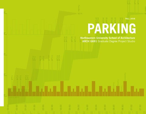
Northeastern University School of Architecture ARCH G691 Graduate Degree Project Studio
16 Left
et 00:00
3 Left
24 Left
25 Left
26 Left
27 Left
29 Left 28 Left
FALL 2008
23 Left 22 Left
+30’-0”
2 Left
1 Left 0 Left
Familiar
PARKING 15 Left 14 Left 13 Left 12 Left 11 Left
9 Left 8 Left 7 Left 6 Left 5 Left 4 Left 3 Left 2 Left
Relative MPH
+10’-0”
1 Left
+10’-0”
10 Left
+20’-0”
85
85%
+40’-0”