Photovoltaic Systems and the National Electric Code
Used throughout the United States and many other countries, the National Electric Code (NEC) is the world’s most detailed set of electrical codes pertaining to photovoltaic (PV) systems.
Photovoltaic Systems and the National Electric Code presents a straightforward explanation of the NEC in everyday language. The new book is based on the 2017 NEC, which will be used widely until 2023, with most of the interpretations and material staying true long after. This book interprets the distinct differences between previous versions of the NEC and the 2017 NEC and clarifies how these Code changes relate specifically to photovoltaic installations.
Written by two of the leading authorities and educators in the field, this book will be a vital resource for solar professionals, as well as anyone preparing for a solar certification exam.
Bill Brooks is Principal Engineer at Brooks Engineering, Vacaville, USA.
Sean White is a Solar PV professor, trainer and contractor in the USA.
Photovoltaic Systems and the National Electric Code
Bill Brooks and Sean White
First published 2018 by Routledge
2 Park Square, Milton Park, Abingdon, Oxon OX14 4RN and by Routledge 711 Third Avenue, New York, NY 10017
The right of Bill Brooks and Sean White to be identified as authors of this work has been asserted by them in accordance with sections 77 and 78 of the Copyright, Designs and Patents Act 1988.
All rights reserved. No part of this book may be reprinted or reproduced or utilised in any form or by any electronic, mechanical, or other means, now known or hereafter invented, including photocopying and recording, or in any information storage or retrieval system, without permission in writing from the publishers.
Trademark notice: Product or corporate names may be trademarks or registered trademarks, and are used only for identification and explanation without intent to infringe.
British Library Cataloguing-in-Publication Data
A catalogue record for this book is available from the British Library
Library of Congress Cataloging-in-Publication Data
A catalog record for this book has been requested
ISBN: 978-1-138-08752-1 (hbk)
ISBN: 978-1-138-08753-8 (pbk)
ISBN: 978-1-315-11030-1 (ebk)
Typeset in Sabon by Apex CoVantage, LLC
1.5
1.6
2.4
6.1 Fuse grounded PV array with one functional grounded conductor
Photovoltaic (PV) is growing fast, and the PV material in the National Electric Code (NEC) is changing faster than anything the NEC has seen since the days of Thomas Edison and Nikola Tesla hashing it out over dc vs. ac. It appeared that Tesla was right when 2-phase ac power1 was installed at Niagara Falls and that ac was the way of the future, but the future is always unpredictable and with PV, dc is making a comeback.
This book is designed to relay to the layperson working in the PV industry the NEC PV-related material and changes as simply as possible, but not simpler. We hope that professional engineers (PEs) and sunburnt solar installers alike will comprehend this easy writing style and be entertained just enough to not be bored learning about a Code that has been known to work better than melatonin on a redeye flight. Since this book is about PV, rather than starting at the beginning of the NEC, we will start with the most relevant article of the NEC, which is Article 690 Photovoltaic (PV) Systems; we will then cover the new Article 691 Large-Scale Photovoltaic (PV) Electric Power Production Facility which modifies Article 690 for large PV systems and then dive into the interconnections of Article 705 Interconnected Electric Power Production Sources where we understand how PV and other power sources can connect to and feed other power sources, such as the utility grid. The next articles we will cover are the articles on energy storage, which are the old Article 480 Storage Batteries and the new and more relevant in 2017 Article 706 Energy Storage Systems. While we are on the subject of energy storage, we will cover the new Article 710 Stand-Alone Systems (which was formerly 690.10) and this will lead us to another new and renewable themed Article 712 Dc Microgrids. We will then go back to the beginning of the NEC and look at Chapters 1 through 4 of the NEC, which apply to all wiring systems, including PV. We will see that, in covering the new and
renewable PV centric articles, we already covered the more important parts of Chapters 1 through 4 used for PV systems and all electric installations, such as Article 250 Grounding and Bonding and Article 310 for wire sizing. There will be many times, when we are covering material in Article 690, that we will go back and forth to other articles, since this is the way to properly use the NEC.
The NEC is updated every three years with a new Code cycle. This edition of Photovoltaic Systems and the National Electric Code reflects the 2017 NEC and will discuss earlier versions of the NEC. When the 2020 NEC comes out, this material will not be obsolete; in fact more than half the PV in the United States is installed in places that adopt the NEC three years after a Code is released. For instance, the state with half of the solar in the US is California, and in California, the 2017 NEC is adopted in 2020 and used until the 2020 NEC is adopted in 2023. It is also interesting to note that the proposals for changes to the NEC are crafted three years earlier, so the material in the 2017 NEC was proposed in 2014 and will be used on a regular basis by inspectors until nine years later. Since the equipment changes
so fast in the PV industry, the Code writers intentionally leave parts of the Code open-ended to make way for new inventions that you may come up with, which will save lives and may make you rich.
The 2017 NEC proposals for Article 690 and for other solar-relevant parts of the Code were first proposed at meetings at NREL in Colorado in 2014 and put on a Word document by Bill Brooks. This Word document grew, and the proposals were refined with a lot of input. These future Codes were later proposed to the top dogs at the National Fire Protection Association by Ward Bower (inventor of the grid-tied inverter) and Bill Brooks of NEC Code Making Panel 4 in Hilton Head, North Carolina.
Now is the time to take out your 2017 NEC and follow along to understand PV and the NEC.
Note
1 The first power plant at Niagara Falls had two phases that were 90 degrees out of phase with each other (weird). Now we use three phases that are 120 degrees out of phase with each other. This is interesting!
Article 690 photovoltaic (PV) systems
Article 690 first came out in a little book known as the 1984 NEC and has been updated and mostly lengthened ever since.
In comparing the original 1984 version of Article 690 to today’s NEC, there are many similarities yet also quite a few differences. Time to dig in!
Let us first list what we are dealing with in Article 690 before we dig deep. This will give us perspective and familiarize us with how to look things up quickly.
The NEC is also known as NFPA 70 and is divided into Chapters, then Articles, then Parts and Sections.
For example, rapid shutdown requirements are found in:
NEC Chapter 6 Special Equipment
Article 690 Solar Photovoltaic (PV) Systems
Part II Circuit Requirements
Section 690.12 Rapid Shutdown of PV Systems on Buildings
Here is what we find in Article 690:
Article 690 solar photovoltaic (PV) systems
Part I general (part)
690.1 Scope [Section 690.1]
690.2 Definitions [There are more NEC definitions in Article 100, such as the definitions for PV, ac and dc.]
690.4 General Requirements [They could not come up with a better title for this category.]
690.6 Alternating Current (ac) Modules
Part II circuit requirements
690.7 Maximum Voltage
690.8 Circuit Sizing and Current
690.9 Overcurrent Protection [Article 240 is also Overcurrent Protection.]
690.10 Stand Alone Systems [This has been moved to Article 710 in the 2017 NEC.]
690.12 Rapid Shutdown of PV Systems on Buildings [Big changes]
Part III disconnecting means
690.13 Photovoltaic System Disconnecting Means
690.15 Disconnection of PV Equipment
Part IV wiring methods
690.31 Methods Permitted
690.32 Component Interconnections
690.33 Connectors
690.34 Access to Boxes
Part V grounding and bonding [Article 250 is also grounding and bonding.]
690.41 System Grounding [Big changes in the 2017 NEC]
690.42 Point of System Grounding Connections
690.43 Equipment Grounding and Bonding
690.45 Size of Equipment Grounding Conductors
690.46 Array Equipment Grounding Conductors
690.47 Grounding Electrode System [Experts argue over a lot of this article, which is interesting to observe.]
690.50 Equipment Bonding Jumpers
Part VI marking
690.51 Modules
690.52 Alternating Current Photovoltaic Modules
690.53 Direct Current Photovoltaic Power Source
690.54 Interactive System Point of Interconnection
690.55 Photovoltaic Systems Connected to Energy Storage Systems
690.56 Identification of Power Sources [This includes new Rapid Shutdown signs.]
Part VII connection to other sources
690.59 Connection to Other Sources [Directs us to Article 705]
Part VIII energy storage systems
690.71 General [Directs us to Article 706]
690.72 Self- Regulated PV Charge Control
Article 690 photovoltaic (PV) systems 7
Now it is time to dive into the detail of Article 690.
Article 690 solar photovoltaic (PV) systems
Part I general (part)
690.1 scope (section 690.1)
Word-for-word NEC:
“690.1 Scope. This article applies to solar PV systems, other than those covered by Article 691, including the array circuit(s), inverter(s), and controller(s) for such systems. [See Figure 690.1(a) and Figure 690.1(b).] The systems covered by this article may be interactive with other electrical power production sources or stand-alone or both, and may or may not be connected to energy storage systems such as batteries. These PV systems may have ac or dc output for utilization.
Informational Note: Article 691 covers the installation of large-scale PV electric supply stations.”
Discussion: For the most part 690.1 is self-explanatory, however, if we read the 2014 and the 2017 NEC carefully, we will notice that energy storage systems (batteries) are no longer part of the PV system. 2017 NEC language:
“may or may not be connected to energy storage systems.”
2014 NEC language:
“may be interactive with other electrical power production sources or stand-alone, with or without electrical energy storage such as batteries.”
It takes some careful analysis of the language, but we see that being connected to batteries in the 2017 NEC is different than with batteries in the 2014 NEC.
So what does this mean for us? Batteries are no longer part of the PV system as of the 2017 NEC and are part of a separate energy storage system that is covered in the new Article 706. Consequently, rapid shutdown and other requirements that are specific to PV systems no longer apply to the batteries.
Figure 1.2 2014 NEC Figure 690.1(a) PV power source Courtesy NFPA
Next, we see diagrams that will show us the dividing line between the PV system and not the PV system.
Section 690.1 also has some figures that we can look at in order to get a picture of what we are talking about.
Figure 1.2 is an image from the 2014 NEC.
Figure 1.3 is an image from the 2017 NEC.
Figure 1.3 is from the 2017 NEC with the added dc-to-dc converter. From comparing these images, the main difference here is the insertion of the dc-to-dc converters. The writers of the NEC left the dc-todc converter definition open-ended for your billion-dollar invention. 2017 dc-to-dc converters are usually one per module, rather than three modules per converter in this image. Take note that, as we will learn coming up in Section 690.12 Rapid Shutdown, in 2019 the 2017 NEC will increase requirements for rapid shutdown on buildings and module level shutdown may be one of the only methods to comply. However, new inventions in the meantime could introduce other methods not currently foreseen.
Figure 1.3 2017 NEC PV Figure 690.1(a) PV power source Courtesy NFPA
It is interesting to note that the solar cells in the diagram have gone from round in the 2014 NEC (really old style) to square in the 2017 NEC (polycrystalline). For someone first learning about solar, it could be confusing to see a solar module with 12 cells and then to see panels made of three modules. It would be even more confusing to have one dc-to-dc converter per three modules that is being connected with fuses to a dc-to-dc converter combining busbar and then off to a dc-to-dc converter output circuit. Dc-to-dc converters being installed in 2017 have a single PV module with a dc-to-dc converter under the module and then a number of dc-to-dc converters connected in series, and then the dc-to-dc converter source circuit is connected directly to the inverter.
1.4 Interactive system [2017 NEC Fig 690.1(b)]
Courtesy NFPA
Figure 1.5 Ac module system [2017 NEC Fig 690.1(b)]
Courtesy NFPA
Images are good to learn from. Next, we will go over the different images in Figures 690.1(B), paying close attention to the various PV system disconnecting means, which separate the PV system covered here in Article 690 from systems covered in other areas of the 2017 Code. Remember, much of this has changed in the 2017 NEC.
Interactive (grid-tied) inverter circuits are very simple. The inverter is used only for PV power; it has no other purpose and therefore is part of the PV system.
A big question installers have is: “What is the difference between an ac module and a microinverter bolted to a PV module?” The answer is that if the PV module was listed to UL1703 while the inverter was bolted to it and the inverter was tested and listed to UL 1741 while bolted to the PV module, then it is an ac module and we do not consider dc part of the product when installing this module.
Figure
If the module and microinverter were not listed together, then we are responsible for applying the NEC to the dc circuit going from the module to the inverter. It is also interesting to note that the word microinverter does not appear in the NEC. The NEC looks at a microinverter as nothing more than a small (micro) inverter.
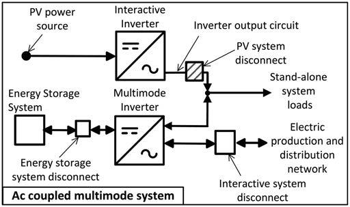
There is a lot of information in Figure 1.6. First of all, dc coupled and multimode are different things, which can go together. A dc coupled system is a PV system that is typically charging batteries with a charge controller connected to a PV array. The inverter in a dc coupled system will be coupled with the inverter and the charge controller working with dc voltage. In fact, it is possible to have a dc coupled system that does not have an inverter, but most people would like to utilize ac electricity with their dc coupled systems.
As we can see in the 690.2 Definitions that we are about to dive into, a multimode inverter is an inverter that can work in different modes, such as stand-alone (off-grid) and interactive (grid-tied). This type of inverter was also known as a bimodal inverter for a time and will have different outputs. One output will go to the stand-alone (backed up) loads and the other output will go to the loads that are not backed up and to the grid. When the power goes down, the interactive output of the inverter
Figure 1.6 Dc coupled multimode system [2017 NEC Fig 690.1(b)]
Courtesy NFPA
Article 690 photovoltaic (PV) systems
will act exactly as an interactive inverter and anti-island (stop sending voltage or current to the grid). No interactive inverter circuit is allowed to be an “island of power” and must disconnect from the grid.
Multimodal vs. hybrid
There is often confusion about multimodal inverters and hybrid PV systems.
A hybrid system is defined in Article 100 Definitions as, “A system comprised of different power sources. These power sources could include photovoltaic, wind, micro-hydro generators, enginedriven generators, and others, but do not include electric power production and distribution network systems. Energy storage systems such as batteries, flywheels, or superconducting magnetic storage equipment do not constitute a power source for the purpose of this definition.” What we are saying here is that being connected to the grid has nothing to do with being hybrid. Hybrid has to do with having multiple sources of power, not including energy storage or the grid. A multimodal system is, as we have mentioned, one that can work in grid (interactive) or off-grid (stand-alone) mode.
Ac coupled systems are becoming more popular. There are arguments on each side, whether it is best to add energy storage to PV systems via ac coupled and dc coupled systems (or both). Ac coupled systems have the benefit of being able to use regular grid-tied inverters in the system and the drawback of having two kinds of inverters.
In Figure 1.7, starting at the upper left, we have a PV array and an interactive inverter, which is the PV system according to the 2017 NEC. On the other hand, according to the 2014 NEC, almost everything in the image is the PV system. We can see that the border that separates the PV system from the rest of the ac coupled multimode system is the PV system disconnect. It is surprising to many that the multimode inverter has no place to connect PV to it. This inverter is connected to an energy storage system (usually batteries) on the dc side and to the grid (electrical production and distribution network) on one ac output and to what I like to call the “ac microgrid” on the other ac circuit, where backed up loads can usually operate. It is also interesting that some manufacturers can make ac coupled systems that will not operate at all when the grid is down. This can be for what is often called “self-consumption” in the industry. These systems will be able to send electricity from the batteries to the loads or the grid when it is
Figure 1.7 Ac coupled multimode system [2017 NEC Fig 690.1(b)]
Courtesy NFPA
beneficial to do so because of utility demand charges, time-of-use rate schedules or because in some places, utility customers are not allowed to export energy.
The stand-alone system in the image above has a few differences with the average stand-alone system we see in the field. First of all, there is usually a charge controller that is connected to three different things. First is the PV array, second is the energy storage system and third is the inverter. These days, it is unusual to have dc loads as shown in Figure 1.8.
Figure 1.8 could also be considered a dc coupled system without a multimode inverter.
690.2 definitions
Because this book is meant to be read with an actual NEC book handy or to be read by someone already familiar with the NEC, we will not repeat every easy to understand definition in Article 690. We will repeat the language of some of the newer and more difficult to understand definitions that a solar professional will have a tendency to use in their career. We will also add discussion to some definitions.
Alternating current (ac) module
Discussion: The question that many solar professionals have is: “What is the difference between an ac module and a microinverter attached
Figure 1.8 Stand-alone system [2017 NEC Fig 690.1(b)]
Courtesy NFPA
to a module?” The answer is that the ac module has the microinverter attached to it before it goes through the UL 1703 PV testing and the UL 1741 inverter testing (also see Figure 1.5, page 10 of this book).
Bipolar photovoltaic array
Discussion: A bipolar PV array is dc power analogy of 120/240Vac power on a house in the US. In a bipolar system there is a positively grounded array section and a negatively grounded array section on the same inverter. This means that we can have voltage to ground that is half of the total voltage that the inverter is getting the benefit of processing. The interesting thing about this, in the 2017 NEC, is that with the 1500Vdc to ground equipment, we can have an inverter with a 3000Vdc input in a ground mount PV system! This is not something anyone is likely to see in his or her backyard, but according to the 2017 Code, it is a possibility.
At NREL in 2014, Sean and Bill made a proposal to require lithium batteries for bipolar arrays for the 2017 NEC, but everyone just laughed at them.
Dc-to-dc converter
Discussion: The dc-to-dc converter definition was put into the Code in 2014 and first put into a diagram in the 2017 NEC. The definition is left rather wide open, so that new equipment not yet in use or invented can be put into use and save lives. For instance, the diagram shows dc-to-dc converters connected to PV source circuits and then the dc-to-dc converters are connected to each other in parallel to make a dc-to-dc converter output circuit. The way we usually see it in practice, at the publication of this book, is with the dc-to-dc converters connected to one PV module per optimizer and then the optimizers are connected together in series and then connected to the inverter. There are some optimizers that work almost the same, but with two modules in series. These optimizers with two modules in series may not comply with module level shutdown requirements that we will learn about when we get to 690.12 Rapid Shutdown. (In 2019, the 2017 NEC may require module level shutdown unless other products are made available that provide similar safety benefits).
Power optimizers
Dc-to-dc converters are commonly referred to in the industry as “power optimizers,” which is really a marketing term. If a dc-to-dc converter did not work as well as advertised or was clipping power (reducing power on purpose), perhaps we would call it a “power-pessimizer.”
Dc-to-dc converter source and output circuits
Discussion: Dc-to-dc converter source and output circuits, which are new terms in the 2017 NEC, are like PV source and PV output circuits, however, they are dc-to-dc converters connected together rather than PV modules. Just like how PV modules connected together in series are a PV source circuit, dc-to-dc converters connected together in series are a dc-to-dc converter source circuits.
String theory
We often call a PV source circuit a “string.” The term string is not in the NEC but is used in the IEC (International Electrotechnical Commission) and many other international codes and
standards. Since everyone in the industry is calling PV source circuits “strings,” would it be acceptable to call dc-to-dc converter source circuits “strings”? Perhaps it is as correct as calling a PV source circuit a “string.”
On another note, I often hear installers calling microinverters that are connected together on a circuit a “string.” I am always correcting the microinverter “string” concept and calling it a “branch” rather than a “string,” since microinverters connected together are generally connected in parallel, like a branch circuit, and do not have that “series-string thing” happening.
It is possible for someone to come up with a microinverter technology that requires microinverters to be connected in series with other microinverters that would be lower voltage ac microinverters and the voltages would add.
Dc-to-dc Converter Output Circuits are dc-to-dc Converter Source Circuits connected together in parallel and could be connected together in a combiner. Dc-to-dc Converter Output Circuits are uncommon, however, the NEC gurus thought it important enough to define and to let the future decide what circuits will be used.
Diversion charge controller
Discussion: A diversion charge controller will divert charge from a battery to prevent the battery from getting overcharged. A diversion charge controller will often send the excess energy to a diversion load, such as a pump or a heating element in a hot water heater. Also included in this definition of a diversion load is sending energy back to the grid, so if we have a grid-tied battery-backup PV system, when the batteries are charged, we will divert the excess energy to the grid.
Electrical production and distribution network
Discussion: This is a fancy name for a grid, which can be a big utility grid or a smaller micro-sized grid such as a groovy college campus.
Functional grounded PV system
One of the biggest theoretical changes in the 2017 NEC for PV turns everything we formerly thought we knew about PV system grounding upside down or we should say right side up!
From now on, common interactive inverters that are either system grounded via a fuse (old-style formerly known as grounded) and systems that are transformerless (formerly known as ungrounded) and do all their magic through electronics in the inverter are hereby considered functionally grounded inverters!
Let’s talk about the “formerly known as grounded” fuse grounded inverters first (may Prince rest in peace). These inverters are system grounded through a fuse. This means that usually a negative, but sometimes a positive dc busbar in the inverter is connected to the ground busbar via a fuse. When enough current goes through the ground wire during a ground fault, then the fuse blows and suddenly the grounded conductor becomes ungrounded. So in this type of system when there is a ground fault, what has been white to indicate it is a grounded conductor may be ungrounded when we are working on it. This previously (no more) required us to have a sign telling us that if a ground fault is indicated, then the grounded conductor may be energized. This is a very confusing label to someone who is not familiar with PV systems. Electricians are used to white-colored grounded conductors to be near ground potential! (Remember: a grounded conductor is a current-carrying conductor that has the same voltage as ground due to a single point of system grounding).
These “formerly known as grounded” inverters had a problem. Large PV systems would often have a few milliamps per module of leakage currents taking the parallel fuse pathway home to the negative bus as some of the electrons took the path through glass, frames, cables, insulation and rails when there were no ground faults. As the system became larger, the leakage became greater and the immediate cure was to upsize the ground fault detection and interruption (GFDI) fuse. With a larger GFDI fuse and a foggy day, some systems would not be able to catch a real ground fault. Even without a foggy day a ground fault that was not severe would stay hidden and the system would keep on making good, clean solar energy. Then what would happen in a few cases is the dangerous outcome. A second ground fault would occur and we have what in tennis they call a double fault. An entire array can get short-circuited and start backfeeding through a single string and poof, smoke and the rest we will leave up to your imagination before someone uses this against us in court.
The solution: “Formerly known as ungrounded” inverters are also known as transformerless inverters, non-isolated inverters or, as I like to call them, magic boxes. It is easier to call these inverters magic than it is to explain the internal workings of these inverters and to explain the workings of a non-isolated grounded ac circuit. Non-isolated inverters
have a reference point to ground related to the internal workings of the inverter, but do not have a grounded conductor. We used to call these inverters European inverters, since having something ungrounded on your house was historically an AHJ no-no in the United States. Then after some modernization, a few puffs of smoke (not a pun) and some explaining, these formerly known as ungrounded inverters soon became the safer norm. After all, they are safer, cheaper and more efficient; safer being the key. These inverters can detect ground faults that are way less than the other inverters. Every day these modern inverters do insulation testing on the PV circuits. They are very sensitive and can detect minor ground faults.
With all of this being said, it is still possible to have a solidly grounded PV array; it’s just not common in the modern era. Perhaps you have a small PV system running a water pump. Your PV array negative might be solidly connected to a ground rod. That would be a solid ground and it would be safe to say that the system is more than “functionally” grounded.
The term functional grounding was taken from Europeans by someone on NEC Code Making Panel 4. “Hey Bill, the Europeans called and they want their functional grounding back!”
Because most of our PV systems are functionally grounded systems, we have a new set of rules that covers all of these functionally grounded systems. No more white negatives (or positives), no more required PV wires (USE-2 is good), no more fuses on two polarities and opening positive and negative in the dc disconnect are required to be functional. We will cover this again as soon as you almost forget it and force it into your long-term memory when we get to the meat of Article 690.
Generating capacity
This is the output of the inverter. This is measured in kW and at 40°C. We often call this our ac system size. 690.7 maximum voltage and 690.8 circuit sizing and current have some special exceptions for systems with a generating capacity over 100kW and Article 691 largescale photovoltaic (PV) power production facilities has exceptions that apply to systems with a generating capacity of 5000kW (5MW) or greater. This definition is new in the 2017 NEC.
Another random document with no related content on Scribd:
vigorously engaged upon a vain effort to preserve order by a passable imitation of Chanticleer saluting the happy morn.
From ‘Q’s’ report of another outbreak of disorder it would appear that in the House meeting in the ‘thirties of the nineteenth century, exchange of personalities went far beyond modern experience. The once heated Maynooth question was to the fore. In the course of an animated set-to between a Mr. Shaw and Daniel O’Connell, the former shouted ‘The Hon. Member has charged me with being actuated by spiritual ferocity. My ferocity is not of the description which takes for its symbol a death’s head and cross bones.’
O’Connell, as a certain fishwife locally famous for picturesque language discovered, was hard to beat in the game of vituperation. Turning upon Shaw, he retorted ‘Yours is a calf’s head and jaw bones.’
‘Q’ records that the retort was greeted with deafening cheers from the Ministerial side where O’Connell and his party were seated. Mr. Shaw’s polite, but perhaps inconsequential, remark had been received with equal enthusiasm by the Opposition.
AFTER THE BATTLE.
�� ������ �����������.
‘Caesar,’ said a Sub-lieutenant to his friend, a temporary Lieutenant R.N.V.R., who at the outbreak of war had been a classical scholar at Oxford, ‘you were in the thick of our scrap yonder off the Jutland coast. You were in it every blessed minute with the battle cruisers, and must have had a lovely time. Did you ever, Caesar, try to write the story of it?’
It was early in June of last year, and a group of officers had gathered near the ninth hole of an abominable golf course which they had themselves laid out upon an island in the great landlocked bay wherein reposed from their labours long lines of silent ships. It was a peaceful scene. Few even of the battleships showed the scars of battle, though among them were some which the Germans claimed to be at the bottom of the sea. There they lay, coaled, their magazines refilled, ready at short notice to issue forth with every eager man and boy standing at his action station. And while all waited for the next call, officers went ashore, keen, after the restrictions upon free exercise, to stretch their muscles upon the infamous golf course. It was, I suppose, one of the very worst courses in the world. There were no prepared tees, no fairway, no greens. But there was much bare rock, great tufts of coarse grass greedy of balls, wide stretches of hard, naked soil destructive of wooden clubs, and holes cut here and there of approximately the regulation size. Few officers of the Grand Fleet, except those in Beatty’s Salt of the Earth squadrons, far to the south, had since the war began been privileged to play upon more gracious courses. But the Sea Service, which takes the rough with the smooth, with cheerful and profane philosophy, accepted the home-made links as a spirited triumph of the handy-man over forbidding nature.
‘Yes,’ said the naval volunteer, ‘I tried many times, but gave up all attempts as hopeless. I came up here to get first-hand material, and have sacrificed my short battle leave to no purpose. The more I learn the more helplessly incapable I feel. I can describe the life of a ship, and make you people move and speak like live things. But a battle is too big for me. One might as well try to realise and set on paper the Day of Judgment. All I did was to write a letter to an old friend, one Copplestone, beseeching him to make clear to the people at home what we really had done. I wrote it three days after the battle, but never sent it. Here it is.’
Lieutenant Caesar drew a paper from his pocket and read as follows:
‘M� ���� C����������,—Picture to yourself our feelings. On Wednesday we were in the fiery hell of the greatest naval action ever fought. A real Battle of the Giants. Beatty’s and Hood’s battle cruisers—chaffingly known as the Salt of the Earth—and Evan Thomas’s squadron of four fast Queen Elizabeths had fought for two hours the whole German High Seas Fleet. Beatty, in spite of his heavy losses, had outmanœuvred Fritz’s battle cruisers and enveloped the German line. The Fifth Battle Squadron had stalled off the German Main Fleet, and led them into the net of Jellicoe, who, coming up, deployed between Evan Thomas and Beatty, though he could not see either, crossed the T of the Germans in the beautifullest of beautiful manœuvres, and had them for a moment as good as sunk. But the Lord giveth and the Lord taketh away; it is sometimes difficult to say Blessed be the Name of the Lord. For just when we most needed full visibility the mist came down thick, the light failed, and we were robbed of the fruits of victory when they were almost in our hands. It was hard, hard, bitterly hard. But we had done the utmost which the Fates permitted. The enemy, after being harried all night by destroyers, had got away home in torn rags, and we were left in supreme command of the North Sea, a command more complete and unchallengeable than at
any moment since the war began. For Fritz had put out his full strength, all his unknown cards were on the table, we knew his strength and his weakness, and that he could not stand for a moment against our concentrated power. All this we had done, and rejoiced mightily. In the morning we picked up from Poldhu the German wireless claiming the battle as a glorious victory—at which we laughed loudly. But there was no laughter when in the afternoon Poldhu sent out an official message from our own Admiralty which, from its clumsy wording and apologetic tone, seemed actually to suggest that we had had the devil of a hiding. Then when we arrived at our bases came the newspapers with their talk of immense losses, and of bungling, and of the Grand Fleet’s failure! Oh, it was a monstrous shame! The country which depends utterly upon us for life and honour, and had trusted us utterly, had been struck to the heart. We had come back glowing, exalted by the battle, full of admiration for the skill of our leaders and for the serene intrepidity of our men. We had seen our ships go down and pay the price of sea command—pay it willingly and ungrudgingly as the Navy always pays. Nothing that the enemy had done or could do was able to hurt us, but we had been mortally wounded in the house of our friends. It will take days, weeks, perhaps months, for England and the world to be made to understand and to do us justice. Do what you can, old man. Don’t delay a minute. Get busy. You know the Navy, and love it with your whole soul. Collect notes and diagrams from the scores of friends whom you have in the Service; they will talk to you and tell you everything. I can do little myself. A Naval Volunteer who fought through the action in a turret, looking after a pair of big guns, could not himself see anything outside his thick steel walls. Go ahead at once, do knots, and the fighting Navy will remember you in its prayers.’
The attention of others in the group had been drawn to the reader and his letter, and when Lieutenant Caesar stopped, flushed and out of breath, there came a chorus of approving laughter.
‘This temporary gentleman is quite a literary character,’ said a tworing Lieutenant who had been in an exposed spotting top throughout the whole action, ‘but we’ve made a Navy man of him since he joined. That’s a dashed good letter, and I hope you sent it.’
‘No,’ said Caesar. ‘While I was hesitating, wondering whether I would risk the lightning of the Higher Powers, a possible court martial, and the loss of my insecure wavy rings, the business was taken out of my hands by this same man to whom I was wanting to write. He got moving on his own account, and now, though the battle is only ten days old, the country knows the rights of what we did. When it comes to describing the battle itself, I make way for my betters. For what could I see? On the afternoon of May 31, we were doing gun drill in my turret. Suddenly came an order to put lyddite into the guns and follow the Control. During the next two hours as the battle developed we saw nothing. We were just parts of a big human machine intent upon working our own little bit with faultless accuracy. There was no leisure to think of anything but the job in hand. From beginning to end I had no suggestion of a thrill, for a naval action in a turret is just gun drill glorified, as I suppose it is meant to be. The enemy is not seen; even the explosions of the guns are scarcely heard. I never took my ear-protectors from their case in my pocket. All is quiet, organised labour, sometimes very hard labour when for any reason one has to hoist the great shells by the hand purchase. It is extraordinary to think that I got fifty times more actual excitement out of a squadron regatta months ago than out of the greatest battle in naval history.’
‘That’s quite true,’ said the Spotting Officer, ‘and quite to be expected. Battleship fighting is not thrilling except for the very few For nine-tenths of the officers and men it is a quiet, almost dull routine of exact duties. For some of us up in exposed positions in the spotting tops or on the signal bridge, with big shells banging on the armour or bursting alongside in the sea, it becomes mighty wetting and very prayerful. For the still fewer, the real fighters of the ship in the conning tower, it must be absorbingly interesting. But for the true blazing rapture of battle one has to go to the destroyers. In a battleship one lives like a gentleman until one is dead, and takes the
deuce of a lot of killing. In a destroyer one lives rather like a pig, and one dies with extraordinary suddenness. Yet the destroyer officers and men have their reward in a battle, for then they drink deep of the wine of life. I would sooner any day take the risks of destroyer work, tremendous though they are, just for the fun which one gets out of it. It was great to see our boys round up Fritz’s little lot. While you were in your turret, and the Sub. yonder in control of a side battery, Fritz massed his destroyers like Prussian infantry and tried to rush up close so as to strafe us with the torpedo. Before they could get fairly going, our destroyers dashed at them, broke up their masses, buffeted and hustled them about exactly like a pack of wolves worrying sheep, and with exactly the same result. Fritz’s destroyers either clustered together like sheep or scattered flying to the four winds. It was just the same with the light cruisers as with the destroyers. Fritz could not stand against us for a moment, and could not get away, for we had the heels of him and the guns of him. There was a deadly slaughter of destroyers and light cruisers going on while we were firing our heavy stuff over their heads. Even if we had sunk no battle cruisers or battleships, the German High Seas Fleet would have been crippled for months by the destruction of its indispensable “cavalry screen.”’
As the Spotting Officer spoke, a Lieutenant-Commander holed out on the last jungle with a mashie—no one uses a putter on the Grand Fleet’s private golf course—and approached our group, who, while they talked, were busy over a picnic lunch.
‘If you pigs haven’t finished all the bully beef and hard tack,’ said he, ‘perhaps you can spare a bite for one of the blooming ’eroes of the X Destroyer Flotilla.’ The speaker was about twenty-seven, in rude health, and bore no sign of the nerve-racking strain through which he had passed for eighteen long-drawn hours. The young Navy is as unconscious of nerves as it is of indigestion. The Lieutenant-Commander, his hunger satisfied, lighted a pipe and joined in the talk.
‘It was hot work,’ said he, ‘but great sport. We went in sixteen and came out a round dozen. If Fritz had known his business, I ought to be dead. He can shoot very well till he hears the shells screaming
past his ears, and then his nerves go. Funny thing how wrong we’ve been about him. He is smart to look at, fights well in a crowd, but cracks when he has to act on his own without orders. When we charged his destroyers and ran right in he just crumpled to bits. We had a batch of him nicely herded up, and were laying him out in detail with guns and mouldies, when there came along a beastly intrusive Control Officer on a battle cruiser and took him out of our mouths. It was a sweet shot, though. Someone—I don’t know his name, or he would hear of his deuced interference from me— plumped a salvo of twelve-inch common shell right into the brown of Fritz’s huddled batch. Two or three of his destroyers went aloft in scrap-iron, and half a dozen others were disabled. After the first hour his destroyers and light cruisers ceased to be on the stage; they had flown quadrivious—there’s an ormolu word for our classical volunteer —and we could have a whack at the big ships. Later, at night, it was fine. We ran right in upon Fritz’s after-guard of sound battleships and rattled them most tremendous. He let fly at us with every bally gun he had, from four-inch to fourteen, and we were a very pretty mark under his searchlights. We ought to have been all laid out, but our loss was astonishingly small, and we strafed two of his heavy ships. Most of his shots went over us.’
‘Yes,’ called out the Spotting Officer, ‘yes, they did, and ricochetted all round us in the Queen Elizabeths. There was the devil of a row. The firing in the main action was nothing to it. All the while you were charging, and our guns were masked for fear of hitting you, Fritz’s bonbons were screaming over our upper works and making us say our prayers out loud in the Spotting Tops. You’d have thought we were at church. I was in the devil of a funk, and could hear my teeth rattling. It is when one is fired on and can’t hit back that one thinks of one’s latter end.’
‘Did any of you see the Queen Mary go?’ asked a tall thin man with the three rings of a Commander. ‘Our little lot saw nothing of the first part of the battle; we were with the K.G. Fives and Orions.’
‘I saw her,’ spoke a Gunnery Lieutenant, a small, quiet man with dreamy, introspective eyes—the eyes of a poet turned gunner. ‘I saw her. She was hit forward, and went in five seconds. You all know
how It was a thing which won’t bear talking about. The Invincible took a long time to sink, and was still floating bottom up when Jellicoe’s little lot came in to feed after we and the Salt of the Earth had eaten up most of the dinner. I don’t believe that half the Grand Fleet fired a shot.’
There came a savage growl from officers of the main Battle Squadrons, who, invited to a choice banquet, had seen it all cleared away before their arrival. ‘That’s all very well,’ grumbled one of them; ‘the four Q.E.s are getting a bit above themselves because they had the luck of the fair. They didn’t fight the High Seas Fleet by their haughty selves because they wanted to, you bet.’
The Gunnery Lieutenant with the dreamy eyes smiled. ‘We certainly shouldn’t have chosen that day to fight them on. But if the Queen Elizabeth herself had been with us, and we had had full visibility—with the horizon a hard dark line—we would have willingly taken on all Fritz’s twelve-inch Dreadnoughts and thrown in his battle cruisers.’
‘That’s the worst of it,’ grumbled the Commander, very sore still at having tasted only of the skim milk of the battle; ‘naval war is now only a matter of machines. The men don’t count as they did in Nelson’s day.’
‘Excuse me, sir,’ remarked the Sub-Lieutenant; ‘may I say a word or two about that? I have been thinking it out.’
There came a general laugh. The Sub-Lieutenant, twenty years of age, small and dark and with the bright black eyes of his mother—a pretty little lady from the Midi de la France whom his father had met and married in Paris—did not look like a philosopher, but he had the clear-thinking, logical mind of his mother’s people.
‘Think aloud, my son,’ said the Commander. ‘As a living incarnation of l’Entente Cordiale, you are privileged above those others of the gun-room.’
The light in the Sub’s eyes seemed to die out as his gaze turned inwards. He spoke slowly, carefully, sometimes injecting a word from his mother’s tongue which could better express his meaning. He
looked all the while towards the sea, and seemed scarcely to be conscious of an audience of seniors. His last few sentences were spoken wholly in French.
‘No—naval war is a war of men, as it always was and always will be. For what are the machines but the material expression of the souls of the men? Our ships are better and faster than the German ships, our guns heavier and more accurate than theirs, our gunners more deadly than their gunners, because our Navy has the greater human soul. The Royal Navy is not a collection of lifeless ships and guns imposed upon men by some external power as the Kaiser sought to impose a fleet upon the Germans, a nation of landsmen. The Navy is only a matter of machines in so far as human beings can only achieve material ends by material means. I look upon the ships and guns as secreted by the men just as a tortoise secretes its shell. They are the products of naval thought, and naval brains, and, above all, of that ever-expanding naval soul (l’esprit) which has been growing for a thousand years. Our ships yonder are materially new, the products almost of yesterday, but really they are old, centuries old; they are the expression of a naval soul working, fermenting, always growing through the centuries, always seeking to express itself in machinery. Naval war is an art, the art of men, and where in the world will one find men like ours, officers like ours? Have you ever thought whence come those qualities which one sees glowing every day in our men, from the highest Admiral to the smallest ship boy—have you ever thought whence they come?’
He paused, still looking out to sea. His companions, all of them his superiors in rank and experience, stared at him in astonishment, and one or two laughed. But the Commander signalled for silence. ‘Et après,’ he asked quietly; ‘d’où viennent ces qualités?’ Unconsciously he had sloughed the current naval slang and spoke in the native language of the Sub.
The effect was not what he had expected. At the sound of the Commander’s voice speaking in French the Sub-Lieutenant woke up, flushed, and instantly reverted to his English self. ‘I am sorry, sir. I got speaking French, in which I always think, and when I talk French I talk the most frightful rot.’
‘I am not so sure that it was rot. Your theory seems to be that we are, in the naval sense, the heirs of the ages, and that no nation that has not been through our centuries-old mill can hope to stand against us. I hope that you are right. It is a comforting theory.’
‘But isn’t that what we all think, sir, though we may not put it quite that way? Most of us know that our officers and men are of unapproachable stuff in body and mind, but we don’t seek for a reason. We accept it as an axiom. I’ve tried to reason the thing out because I’m half French; and also because I’ve been brought up among dogs and horses and believe thoroughly in heredity. It’s all a matter of breeding.’
‘The Sub’s right,’ broke in the Gunnery Lieutenant with the poet’s eyes; ‘though a Sub who six months ago was a snotty has no business to think of anything outside his duty. The Service would go to the devil if the gun-room began to talk psychology. We excuse it in this Sub here for the sake of the Entente Cordiale, of which he is the living embodiment; but had any other jawed at us in that style I would have sat upon his head. Of course he is right, though it isn’t our English way to see through things and define them as the French do. No race on earth can touch us for horses or dogs or prize cattle—or Navy men. It takes centuries to breed the boys who ran submarines through the Dardanelles and the Sound and stayed out in narrow enemy waters for weeks together. Brains and nerves and sea skill can’t be made to order even by a German Kaiser. Navy men should marry young and choose their women from sea families, and then their kids won’t need to be taught. They’ll have the secret of the Service in their blood.’
‘That’s all very fine,’ observed a Marine Lieutenant reflectively; ‘but who is going to pay for it all? We can’t. I get 7s. 6d. a day, and shall have 11s. in a year or two; it sounds handsome, but would hardly run to a family. Few in the Navy have any private money, so how can we marry early?’
‘Of course we can’t as things go now,’ said the Gunnery Lieutenant. ‘But some day even the Admiralty will discover that the English Navy will become a mere list of useless machines unless the
English naval families can be kept up on the lower deck as well as in the ward-room and gun-room. Why, look at the names of our submarine officers whenever they get into the papers for honours. They are always salt of the sea, names which have been in the Navy List ever since there was a List. You may read the same names in the Trafalgar roll and back to the Dutch wars. Most of us were Pongos before that—shore Pongos who went afloat with Blake or Prince Rupert—but then we became sailors, and so remained, father to son. I can only go back myself to the Glorious First of June, but some of us here in the Grand Fleet date from the Stuarts at least. It is jolly fine to be of Navy blood, but not all plum jam. One has such a devil of a record to live up to. In my term at Dartmouth there was a poor little beast called Francis Drake—a real Devon Drake, a genuine antique—but what a load of a name to carry! Thank God, my humble name doesn’t shine out of the history books. And as with the officers, so with the seamen. Half of them come from my own county of Devon—the cradle of the Navy. They are in the direct line from Drake’s buccaneers. Most of the others come from the ancient maritime counties of the Channel seaboard, where the blood of everyone tingles with Navy salt. The Germans can build ships which are more or less accurate copies of our own, but they can’t breed the men. That is the whole secret.’
The Lieutenant-Commander, whose war-scarred destroyer lay below refitting, laughed gently. ‘There is a lot in all that, more than we often realise when we grumble at the cursed obstinacy of our old ratings, but even you do not go back far enough. It is the old blood of the Vikings and sea-pirates in us English which makes us turn to the sea; the rest is training. In no other way can you explain the success of the Fringes, the mine-sweepers, and patrols, most of them manned by naval volunteers who, before the war, had never served under the White Ensign nor seen a shot fired. What is our classical scholar here, Caesar, but a naval volunteer whom Whale Island and natural intelligence have turned into a gunner? But as regards the regular Navy, the Navy of the Grand Fleet, you are right. Pick your boys from the sea families, catch them young, pump them full to the teeth with the Navy Spirit—l’esprit marine of our bi-lingual Sub here —make them drunk with it. Then they are all right. But they must
never be allowed to think of a darned thing except of the job in hand. The Navy has no use for men who seek to peer into their own souls. They might do it in action and discover blue funk. We want them to be no more conscious of their souls than of their livers. Though I admit that it is devilish difficult to forget one’s liver when one has been cooped up in a destroyer for a week. It is not nerve that Fritz lacks so much as a kindly obedient liver. He is an iron-gutted swine, and that is partly why he can’t run destroyers and submarines against us. The German liver is a thing to wonder at. Do you know—’ but here the Lieutenant-Commander became too Rabelaisian for my delicate pen.
The group had thinned out during this exercise in naval analysis. Several of the officers had resumed their heart-and-club-breaking struggle with the villainous golf course, but the Sub, the volunteer Lieutenant, and the Pongo (Marine) still sat at the feet of their seniors. ‘May I say how the Navy strikes an outsider like me?’ asked Caesar diffidently. Whale Island, which had forgotten all other Latin authors, had given him the name as appropriate to one of his learning.
‘Go ahead,’ said the Commander generously. ‘All this stuff is useful enough for a volunteer; without the Pongos and the Volunteers to swallow our tall stories, the Navy would fail of an audience. The snotties know too much.’
‘I was going to speak of the snotties,’ said Caesar, ‘who seem to me to be even more typical of the Service than the senior officers. They have all its qualities emphasised, almost comically exaggerated. I do not know whether they are never young or that they never grow old, but there is no essential difference in age and in knowledge between a snotty six months out of cadet training and a Commander of six years’ standing. They rag after dinner with equal zest, and seem to be equally well versed in the profound technical details of their sea work. Perhaps it is that they are born full of knowledge. The snotties interest me beyond every type that I have met. Their manners are perfect and in startling contrast with those of the average public school boy of fifteen or sixteen—even in College at Winchester—and they combine their real irresponsible
youthfulness with a grave mask of professional learning which is delightful to look upon. I have before me the vision of a child of fifteen with tousled yellow hair and a face as glum as a sea-boot, sitting opposite to me in the machine which took us back one day to the boat, smoking a “fag” with the clumsiness which betrayed his lack of practice, in between bites of “goo” (in this instance Turkish Delight), of which I had seen him consume a pound. He looked about ten years old, and in a husky, congested voice, due to the continual absorption of sticky food, he described minutely to me the method of conning a battleship in manœuvres and the correct amount to allow for the inertia of the ship when the helm is centred; he also explained the tactical handling of a squadron during subcalibre firing. That snotty was a sheer joy, and the Navy is full of him. He’s gone himself, poor little chap—blown to bits by a shell which penetrated the deck.’
‘In time, Caesar,’ said the Commander, ‘by strict attention to duty you will become a Navy man. But we have talked enough of deep mysteries. It was that confounded Sub, with his French imagination, who started us. What I really wish someone would tell me is this: what was the “northern enterprise” that Fritz was on when we chipped in and spoilt his little game?’
‘It does not matter,’ said the Gunnery Lieutenant. ‘We spoilt it, anyhow. The dear old newspapers talk of his losses in big ships as if they were all that counted. What has really crippled him has been the wiping out of his destroyers and fast new cruisers. Without them he is helpless. It was a great battle, much more decisive than most people think, even in the Grand Fleet itself. It was as decisive by sea as the Marne was by land. We have destroyed Fritz’s mobility.’
The men rose and looked out over the bay. There below them lay their sea homes, serene, invulnerable, and about them stretched the dull, dour, treeless landscape of their northern fastness. Their minds were as peaceful as the scene. As they looked a bright light from the compass platform of one of the battleships began to flicker through the sunshine—dash, dot, dot, dash. ‘There goes a signal,’ said the Commander. ‘You are great at Morse, Pongo. Read what it says, my son.’
The Lieutenant of Marines watched the flashes, and as he read grinned capaciously. ‘It is some wag with a signal lantern.’ said he. ‘It reads: Question—Daddy,—what—did—you—do—in—the—Great— War?’
‘I wonder,’ observed the Sub-Lieutenant, ‘what new answer the lower deck has found to that question. Before the battle their reply was: “I was kept doubling round the decks, sonny.”’
‘There goes the signal again,’ said the Pongo; ‘and here comes the answer.’ He read it out slowly as it flashed word after word: ‘“I ���� ��� ���� ����, �����”’
‘And a dashed good answer, too,’ cried the Commander heartily.
‘That would make a grand fleet signal before a general action,’ remarked the Gunnery Lieutenant. ‘I don’t care much for Nelson’s Trafalgar signal. It was too high-flown and sentimental for the lower deck. It was aimed at the history books, rather than at old tarrybreeks of the fleet a hundred years ago. No—there could not be a better signal than just “Lay the Guns True”—carry out your orders precisely, intelligently, faultlessly. What do you say, my Hun of a classical volunteer?’
‘It could not be bettered,’ said Caesar.
‘I will make a note of it,’ said the Gunnery Lieutenant, ‘against the day when, as a future Jellicoe, I myself shall lead a new Grand Fleet into action.’
L’ILE NANCE.
�� ������� �����.
Nance was a tomboy, or whatever may be the equivalent of this type in the doggy world, and she looked it. An ungainly body, clad in a rough coat of silver and grey on a foundation of brown, carried a head that appeared ill-shaped because of the unusual width of skull. Over her forehead continually straggled a tangle of hairs that mixed with others growing stiffly above her snout, and through this cover were to be seen two pearly eyes that were wondrously bright and intelligent. She had a trick, too, of tossing her head in a manner suggestive of nothing so much as a girl throwing back the curls from face and shoulders, and it seemed to emphasise the tomboy in Nance. But she had sterling qualities, of which her broad skull and quick eyes gave more than a hint. If ungainly, her little body was untiring and as supple as a whiplash, and her legs were as finely tempered steel springs. She had, too, a rare turn of speed, and it was the combination of these gifts with her remarkable intelligence that in later days made her the most noted dog in Craven.
Her puppyhood was unpromising. Indeed, for one born on a farm, where is lack neither of shelter nor food, her earliest hours were doubly perilous, for, in addition to the prospect of a watery grave in a bucket, her existence, and that of the whole litter, was threatened by negligent nursing. Fate had given the little family a mother not only herself young, but of all dogs that ever worked on a farm the most irresponsible. It was quite in keeping with her reputation that Lucy should bring her children to birth in the exposed hollow trunk of a tree and then forget the blind, sprawling, whimpering puppies for hours together. It was going hard with the weaklings when fate again took a hand in their welfare, this time in the person of young Zub.
It had become evident to the farm folk, to whom matters of birth and reproduction are commonplaces of daily life, that Lucy’s new
duties had come upon her, and it was plainly evident, too, before the third day had run, that she was neglecting them. It was then that young Zub, or Zubdil, as he was indifferently called, either name serving to distinguish him from Owd Zub, his father, actively bestirred himself. Hitherto he had done no more than keep his eyes and ears open as he moved about the farm buildings, but neither soft whimper nor the sound of tender noses nuzzling against a warm body had rewarded him. His first deliberate efforts were to watch Lucy’s comings and goings, in the hope of tracing her hiding-place. But the mother dog, a poacher at heart and with all a four-footed poacher’s cunning, had easily beaten him at this game. When he recognised this, angry at the thought that somewhere a small family was suffering, he soundly cuffed her about the ears in the hope that she would bolt for her hiding-place and her blind charges. But the graceless one, howling, raced no further than to her kennel, and from its depths kept one watchful eye open for further developments.
‘Drat thee,’ cried Zubdil, as his experiment went wrong, ‘but I’ll find ’em yet.’ He turned and slowly entered the kitchen, where Owd Zub was quietly chuckling to himself.
‘Shoo’s bested thee, reight an’ all, this time,’ he said. ‘Doesn’t thy books tell thee owt?’
It was a thrust he was fond of making. Zubdil’s strongly developed taste for reading was something beyond the old farmer’s understanding. He would have given but occasional heed to it had not the younger man taken up works on scientific farming and breeding, and also studied these subjects in a course of postal lessons with the Agricultural Department at the Northern University. New ideas thus acquired often clashed with the father’s ingrained conservative methods, and they left him sore. A chance to get in a sly dig at this ‘book larning’ was too good to be missed. He chuckled again as he asked the question.
The younger man laughed. He was broadening in more ways than one, and he bore no malice. ‘Happen they do,’ he said. ‘Yo just watch, fayther, an’ happen yo’ll leearn summat.’
He reached up to the blackened oak beam that spanned the ceiling, took down his gun, and strolled casually out across the yard. In a moment Lucy had tumultuously burst out of the kennel and was dancing about him, all animation and keenness. Graceless she might be, and lacking in the discharge of her mothering duties, but heart and soul she was a lover of sport. At the sight of the gun she was in transports. Unheeding her, young Zub passed on through the gate. Wriggling through ere it closed, Lucy was after him and away in front of him like a streak, making river-wards. There, as well she knew, were the plumpest rabbits. When the old dalesman, his curiosity whetted, reached a point where he could see without being seen, the two were ranging the low field where runs the Wharfe. Steadily they passed along through Dub End and into Lang Pasture, the gun still hooked in the curl of the man’s arm, then as they came through the field gate together into the High Garth Lucy’s tail suddenly drooped. She hesitated, turned about in indecision, and finally, disregarding the sharp whistle calling her to heel, slid off up the hill under the wallside and vanished by the riven oak.
‘Dang it,’ said Owd Zub, greatly interested, and understanding, ‘I owt to ha’ knawn shoo’d ha’ gooan to ’em if they came owt near ’em.’
By the time he arrived on the spot, and he walked across the field with a great show of carelessness, Zubdil had the whimpering youngsters on the grass and was examining them. Couched near by, her tail going in great pride, Lucy was mothering each one as it was laid down again.
‘They’re a poor lot,’ said the elder man, eyeing them critically, and discreetly making no reference to the finding of them; ‘put ’em ivvery one i’ t’ pail.’
Zubdil did not reply immediately. He was watching one puppy, more vigorous than any of the rest, trying to prop itself up on its forelegs. Its sightless eyes were turned towards him, its tiny nostrils were working, and there was a decided quiver—it was an immature wagging—in its wisp of a tail. He picked it up again. A tiny patch of red slid out and licked his hand, and there were faint noises that brought Lucy’s ears to the prick. Zubdil laughed.
‘Sitha for pluck, fayther,’ he cried. ‘This is best o’ t’ lot. I’se keeping this for mysen.’
‘Thou’ll drown t’ lot,’ said his father, sharply ‘We’ve dogs enough on t’ farm. Besides, they’re hawf deead.’
They are sparing of speech, these Craven dalesmen, but their words are ever to the point. They have also a stiff measure of obstinacy in their constitution, as have all men whose forebears for generations have lived and died amid the everlasting hills. Obstinacy now showed in the younger man. He put the youngster down beside the mother dog, gathered up the others into a bag that he took from his capacious pocket, and rose. Lucy was up in an instant, ears cocked. Zubdil checked her sternly.
‘Lig thee theer,’ he ordered, and she resumed her nursing under constraint. Young Zub turned to the elder.
‘I’se keeping it,’ he announced, briefly.
The other knew that tone, and gave in. ‘Well,’ grudgingly, ‘I’se heving nowt to do wi’ it, then. An’ if theer’s another licence to get, tha pays for it thysen.’
So the pup was spared, and she flourished and grew apace. Nance, he called her, after one from a neighbouring farm, thoughts of whom had been occupying his mind a good deal of late. He ventured to tell her what he had done when one evening, by chance that had been occurring frequently of late, he met her by the old bridge. The girl reddened with pleasure at the implied compliment, giggled a little, and gave him a playful nudge with her elbow. It was a nudge that would have upset many a city-bred man. ‘Thou’s a silly fond fellow,’ she said, but there was no reproach in her words. Rather was it that in turn he was pleased. It was a little incident that marked a distinct advance in their relations.
It was also an incident that led young Zub to take more interest in the dog’s welfare than otherwise he might have done. Dimly floating at the back of his mind, tinged with romance, was the idea that the four-footed Nance ought to be worthy of the name she bore. It led him to take her education in hand seriously, and to the task he
brought all his fieldcraft, his native shrewdness, and his great patience. He began early, when she was not yet half grown and still a playful puppy; but, early as he was, someone was before him. Whatever her demerits as a mother, Lucy excelled in woodcraft and the art of the chase. She had the soul of an artist for it, which was perhaps why, as an ordinary working farm dog, she was an indifferent success. And what she knew she taught her daughter, taking the young one with her as soon as Nance was strong enough to stand these excursions. Their favourite time was dawn of day, and their hunting-ground the woods that mantled the breast of the moors high above the farm, or the sandy stretches along Wharfe side, where fat rabbits were abundant. Nance was an apt pupil. She learned to stalk, to obliterate herself behind seemingly inadequate cover, to crawl almost without action visible to the eye, and her instinct for choosing the moment for the final fatal rush was not bettered even in the older dog.
Thus it happened that when Zubdil took up her training the ground had been prepared for him better than ever he knew. Yet he began his task opportunely, for Nance was at the parting of the ways. Lucy was a clever dog, but her best and finest qualities, neglected through want of recognition, had deteriorated until she was now no more than a cunning hunter. The little dog—l’ile Nance she was to everybody—inherited all her mother’s cleverness, and, happily for her, Zubdil took her in hand while yet she was in her plastic, impressionable days. He made her his constant companion. If he went no further than the length of the field to fasten up the chickens safe from the predatory fox, he called her to accompany him. If he went on to the moor, or to the village, or to a neighbouring farm, she was with him. And she was taught to do strange things. Sometimes she was sent chasing round a field and brought back to heel in zigzag tracings. At other times she was bidden to crouch by a gate and to stir not at all until his return. Sometimes she was sent ahead at full gallop and then made to stop dead and lie prone, when he would overtake and pass her, man and dog alike apparently unconscious of each other’s presence, save for the way in which those pearly eyes of hers watched his every movement.
It was all done with no more language than can be conveyed in a whistle. But expressive! With his ash stick tucked under one arm Zubdil would thrust the better part, as it seemed, of both hands into his mouth, whence would proceed now a single piercing call, now a prolonged high-pitched note, now a series of staccato commands, and ever and again fluty modulations as if a blackbird had joined in the business. And every note had a definite meaning. It was a great game for Nance, who at these times was nothing more than two bright eyes and a pair of ever-working ears. She strove to please and worked hard, and when it dawned upon the deliberately moving mind of the young dalesman that he had a dog of unusual parts it stimulated him to greater efforts. It also stimulated him to secrecy, though why he could not have explained.
He gave her experience in the rounding-up of the half-wild, hardy, half-bred sheep on the moorlands, and here she learned to work dumbly, without yielding to the temptation to nip the flying legs of the nervous fleeces. It was on these uplands, too, that he received his first meed of praise, and it fired the smouldering pride in his heart and lifted him out of the ordinary workaday rut. For it gave him an idea. It was dipping-time, when the moors had to be thoroughly scoured for the sheep, and from a dozen farms in the dale below men had gathered together to co-operate in the work. With them came their dogs; dogs that barked and fought, dogs that raced hither and thither irresolutely trying to obey the many and confusing whistlings, doing their best to please all and giving satisfaction to none. Young Zub stood on a knoll a little apart, and at his bidding a silver and grey-brown form flashed among the bracken and the ling, sometimes buried from sight, at times only the tips of pricked ears visible, but always making a wider and further stretching circle than the others. And wherever Nance ranged sheep came into view and were deftly piloted to the common gathering-ground.
It was Long Abram who first recognised what she was doing.
‘That theer young dog o’ thy lad’s is doing weel,’ he said, turning to Owd Zub. ‘It’ll mak a rare ’un i’ time.’