PHANTOM II
INTRODUCTION
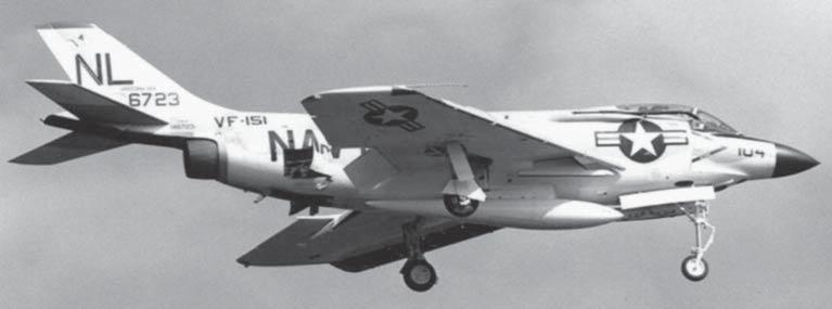
F3H-2 Demon BuNo 146723, one of only 32 delivered from an order for 108. The remainder of the order was canceled. VF-151 Vigilantes converted to the F-4B Phantom II in 1964 and made the naval Phantom’s last carrier landing on March 24, 1986. (US Navy)
When the first F4H-1 emerged from the McDonnell Aircraft Company’s St Louis factory in May 1958 some observers undoubtedly reconsidered the old adage, “if it looks right it will fly right.” Its upswept outer wing panels, severely drooped tail-plane and pendulous nose prompted humorists to suggest that the fighter had been rolled out upside down. Conceived as a naval interceptor, its bulky dimensions did not imply fighter-like performance to pilots brought up on nimble dogfighters like the F-86 Sabre. Closer inspection revealed a lack of guns (previously deemed essential for a true fighter) and a second cockpit, very much at odds with the established solo fighter mentality. When those skeptics heard that the aircraft could carry up to 16,000lb of ordnance (roughly the loaded weight of an F-86A Sabre) and nearly 13,000lb of fuel (2,000lb heavier than an empty F-86A), that fighter designation would have seemed more puzzling. However, a glance at the huge, twin jet exhausts would have revealed the fighter’s main strength: more raw power than any previous fighter could muster. With more than seven times the thrust of the F-86A, the F4H-1 could take full advantage of its load-carrying performance and turn its apparent disadvantages into war-winning fighter-bomber qualities.
Although the US Air Force had been interested in the F4H-1 from the outset, it was the revelation of the fighter’s substantial ordnance-carrying capability that swung a decision to break precedent and order a US Navyinspired design from a company that had worked mainly to Navy contracts.
In October 1945 McDonnell received its first USAF task. Reviving the “parasite fighter” concept, the company designed the XF-85 Goblin, a tiny jet fighter carried beneath Strategic Air Command’s mighty B-36 intercontinental bombers for limited air defense over targets. This project was quickly abandoned, but in 1947 the McDonnell design team under Herman D. Barkey produced a far more practical bomber escort, the long-range, twin-jet XF-88. This evolved into the F-101 Voodoo escort fighter by May 1953, and 77 F-101As were ordered. Displaying their customary skill in maximizing the potential of each design, McDonnell adapted the Voodoo to changing USAF demands, giving the F-101A/C nuclear strike capability. Further redesign yielded the RF-101A/C reconnaissance variant, a stalwart performer in Vietnam and numerous Cold War scenarios. Adding a second cockpit, air-toair missiles and an advanced Hughes MG-13 fire control system in 1956 gave the USAF and Royal Canadian Air Force the F-101B/F and long-serving CF-101B all-weather interceptors.
The Voodoo was large and heavy, 67.5ft long in its RF-101A/C form and weighing up to 52,400lb. It followed McDonnell’s well-tried, twin-jet approach to providing enough thrust and an element of safety for over-water operations. The company’s only single-engined production fighter, the F3H Demon, had been critically under-powered. When work began in 1945 on the McDonnell’s first design, the FH-1 Phantom (the first jet designed for aircraft carrier use), its two jet engines yielded only 1,600lb of thrust each. Sixty were produced and over 850 of a developed version, Barkey’s successful F2H Banshee, were delivered to the US Navy and Royal Canadian Navy. Specialized, radar-equipped and reconnaissance variants were included, but performance was still limited by a total thrust of around 7,000lb. Versatile Banshees fought in the Korean War and the aircraft brought considerable profit to McDonnell, remaining in production until 1953, the year in which design work began on the F4H. In its definitive F-4 Phantom versions the resultant aircraft is often judged the greatest jet fighter ever built. Its production run of 5,201 exceeds that of any other modern Western fighter aircraft. It served with 83 wings and groups of the USAF and Air National Guard, 60 units of the US Navy and US Marines, and 11 other nations’ air forces. With frequent updates this fighter, which entered operational service in 1961, will still be in front-line use with several air forces up to 55 years later. This partly reflects the aircraft’s relatively low initial purchase cost compared to the billions of dollars required to purchase a few of its 21st-century successors, but it is primarily a recognition of the F-4’s sheer quality in performance and adaptability. In the skies above Southeast Asia and the Middle East, F-4s flew countless combat sorties delivering a vast range of ordnance against punishing defenses, with reconnaissance data, protection from enemy defenses and fighter escort often being provided by other Phantoms. F-4 crews have claimed victories over more than 350 enemy aircraft in aerial combat since 1965. It is unlikely ever to have an equal.
DESIGN AND DEVELOPMENT
The McDonnell F2H Banshee’s immediate successor, the F3H Demon, reversed the company’s profitable financial ascent, almost bankrupting it in 1954. The end of the Korean War terminated F2H production – an additional blow. A Navy-sponsored engine competition in 1947 had produced the
1. Radar scanner dish
2. AN/APQ-120 fire control radar unit
3. Ammunition drum for M61 gun (639 rounds)
4. M61A1 six-barrel rotary cannon
5. Nose undercarriage unit
6. Pilot’s right-hand panels with communications, navigation and lighting controls
7. Battery
8. Intake ramp
9. Centre-line fuel tank (600 gallons)
10. Air intake duct
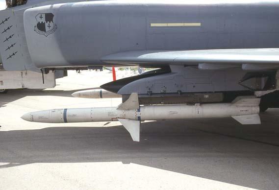
11. AIM-9E Sidewinder missiles on Aero-3B rails
12. External drop tank (370 gallons) and integral pylon
13. Main landing gear bearing
14. Integral fuel tank
15. Position light
16. Hydraulic actuators for flaps and ailerons
17. AIM-7E-2 Sparrow missile in rear missile bay
18. Tail-hook
19. Engine afterburner section
20. Brake parachute container
21. Fuel vent
22. Stabilator feel system pressure probe
23. Stabilator hydraulic actuator
24. Number 7 fuel tank
25. Fuel system piping
26. J79-GE-17 compressor face
27. Number 2 fuel tank
28. Retractable in-flight refuelling receptacle
29. Integral fuel tank
30. Avionics equipment bay
31. Martin Baker Mk H7 ejection seat (both cockpits)
32. Pilot’s left-hand panels with throttles, autopilot and oxygen controls
33. Lead-computing optical sight set (LCOSS)
34. ADF antenna
35. Gun compartment vent
36. Pitot tube
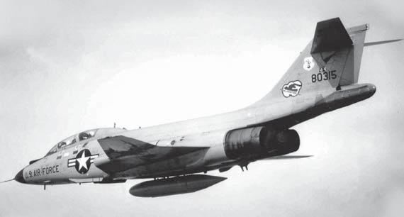
The USAF Phantom’s immediate predecessor at McDonnell, the F-101 Voodoo, reverted to the company’s usual twin-engined layout, adding (for the F-101B interceptor version) a second cockpit for a radar operator, with strengthened undercarriage and bigger tires like the F-4C Phantom. Armament, carried internally, included the Hughes GAR-8 (AIM-4) Falcon, which proved less successful in air-to-air combat for the F-4D/E Phantom. (USAF)
Westinghouse J40, promising 10,500lb of afterburning thrust. It never met that target, and an increase in aircraft weight from 22,000lb to 29,000lb as the Navy switched its role from short-range interception to long-range air superiority seriously reduced the F3H’s design performance. It lost a fly-off competition with Chance Vought’s F8U Crusader as the Navy’s new supersonic day fighter. After several accidents with J40-powered F3H-1s, chief designer Richard Deagan was allowed to replace the J40 with the established Allison J71 (producing 14,250lb of afterburning thrust) for the 459 F3H-2/2M Demons that eventually entered USN service from 1956. Twenty-nine earlier F3H-1Ns, unable to take J71s, were scrapped. Although the Demon remained stubbornly subsonic, it provided experience of the Sperry Sparrow III (AIM-7C) and its associated APG-51A fire control radar, invaluable in developing the F4H-1. It also reinforced McDonnell’s belief in twin powerplants.
Despite its disappointing performance, the Demon provided a solid foundation for the F4H. When studies for a new fighter began in McDonnell’s advanced-design “cage” at St Louis in 1953, they initially proposed little more than a twin-engined Demon to recoup some of the investment in the stalled F3H program. This proposal, suitably modified, won a September 1954 “letter of intent” for an all-weather, two-seat attack aircraft. The initial $38m contract saved the firm, but it also pressed McDonnell to experiment with new technology. The aircraft was re-named AH-1 (their first “attack” design) without specific design parameters from the USN, whose attack mission objective actually required a larger aircraft, which became the North American A-5 Vigilante. AH-1 was reallocated to the Navy’s fighter design branch in December 1954, where it remained a vague project until July 1955.
Meanwhile, Barkey’s team had drafted numerous F3H-G/H variations. The introduction of Forrestal-class supercarriers allowed space for larger aircraft, and this inspired David S. Lewis, the project director, to explore multimission design options. Retaining the AH-1 attack capability, his team devised cost-saving interchangeable nose sections to convert the aircraft from a single-seat, gun-armed attacker to a photo-reconnaissance or ECM (electronic countermeasures) platform. Two-seat noses offered training, advanced ECM or airstrike coordination versions. Although nose-changing aboard a carrier was soon deemed impractical, the idea of concentrating mission-adapted electronics for radar interception, reconnaissance, or strike
missions in the forward fuselage simplified the production of gun-fighter, reconnaissance, and ECM versions of the Phantom in later years.
To avoid “Demonic” powerplant problems, the designers initially drafted two versions: the F3H-G with the proven J65 engine (a license-built British Armstrong Siddeley Sapphire turbojet), and the better-performing F3H-H with the General Electric J79 developed for the USAF’s Mach 2 B-58A Hustler bomber. The US Navy placed their long lead-time J79 order in 1954 and the engine accrued considerable hours in its first service platform, the Lockheed F-104 Starfighter, by the end of 1956. In all, 17,000 examples were produced in 17 versions, including license-built units in Japan, Europe, Canada, and Israel. For the Phantom, it proved to be an extraordinarily reliable, hardy, driving force. The US Navy anticipated that the combined thrust of two J79s would confer excellent climb-to-interception performance and maneuverability in the vertical plane. The unveiling in September 1954 of the Soviet MiG-19, thought to be capable of Mach 1.5, required equivalent speed from the McDonnell design.
Superior air-to-air performance became the main priority for the McDonnell designers from April 1955, when the Navy announced that it needed a fleet defense fighter rather than an AH-1-type attacker. From that point the term F4H-1 was used to define this aircraft, which would patrol near a carrier group, extending loiter time by using one engine and then responding at supersonic speed to threats from high-flying attackers delivering nuclear bombs or stand-off missiles. Attack capability was to be deleted, but fortunately the design was already too far advanced for this to be economical and the airframe retained five structural hard-points that would be the basis for the Phantom’s ordnance-carrying muscle. The Navy’s fighter branch also specified all-weather performance, requiring complex electronics. Lewis’s team felt that this implied a second crew member, a decision reinforced by pressure from the USN guided missile branch in June 1956 to make the Sperry Sparrow III missile the primary armament, with backup from Sidewinder short-range missiles and a gun. An April 1957 revision deleted the gun, a widespread move in aircraft design at that time as it was felt that aerial combat would be conducted at long range with missiles rather than through “dogfighting.” Interceptors faced bombers flying well above the fighters’ service ceiling, requiring long-range missiles fired from a “snap-up” zoom climb by the interceptor.
F4H-1 BuNo 149405 (USAF serial 62-12168), one of a pair of Production Block 9 aircraft borrowed as F-110As for TAC’s 120-day evaluation in 1962. Another 27 F4H-1s were loaned to initiate the USAF training program at McDill AFB. Carriage of AIM-7D Sparrow missiles on the inboard pylons and four fuselage stations shows the Naval Phantom II’s primary interception role. (McDonnell Aircraft Company)
By the time that this F-4C18-MC (63-7526) reached the 15th TFW at McDill AFB, Florida in June 1964, McDonnell had already built 547 Phantoms, including 121 F-4Cs. This TAC wing detached its 45th TFS to Ubon RTAFB, Thailand between April 4 and August 10, 1965, a deployment that included the USAF’s first Phantom II combat strike missions and first two MiG kills. (R. Besecker via Norman Taylor)
These US Navy requirements were built into the design, which still included multimission possibilities. In June 1955 a USN requirement was issued for a two-seat, all-weather fighter for missile-armed interception, and a contract for seven F4H-1 prototypes followed in July. Rather than taking the long route of flight-testing a series of airframe changes to the F3H-H baseline model, Barkey and Lewis had invested heavily in wind-tunnel testing and computers since 1954. After testing 75 wing designs, the F3H wing-sweep angle was retained but the outer wing was thinned. A Demon/Voodoo-like rear fuselage was clad in heat-resistant titanium. The fuselage was given the contoured “coke bottle” area rule profile recommended by the National Advisory Committee on Aeronautics (NACA), reducing drag-induced buffeting at transonic speeds. A stability augmentation system was designed to defeat “roll coupling”, when oscillations in both roll and yaw if a pilot turned at supersonic speed could throw the aircraft out of control. A larger, thinner vertical stabilizer, built partly from innovative honeycomb structures, also added directional stability, overcoming a problem that had caused the loss of many early supersonic fighters. In addition the outer wing panels were given 12 degrees of dihedral, partly to overcome a small anhedral angle in the overall wing structure but mainly to enhance stability in a rolling maneuver. The horizontal stabilizer (stabilator) was then canted downwards, further increasing roll stability.
The F4H-1’s other distinctive visual feature, its pendulous radome, was lacking from the first example that began ground tests in April 1958. The first two prototypes were built to take the Westinghouse APQ-50 search and track radar that McDonnell had used in the Demon and F2H-3 Banshee. Inadequate detection range using the 24-inch diameter antenna originally specified meant that a larger, 32-inch antenna was used for a revised radar, redesignated APQ72. The increased size demanded an unprecedentedly large fibreglass radome fabricated by the Virginia-based Brunswick Company. Robert Little made the first F4H-1 flight on May 16, 1958. Mach 1.3 was achieved on the third flight, and testing moved to Edwards AFB. Modified air intakes improved the innovative variable-geometry’s supersonic airflow, but the aircraft proved its basic soundness despite its technical complexity. On July 3, 1959, the McDonnell Aircraft Company’s 20th anniversary, James Smith McDonnell, company president and chairman, named the F4H-1 “Phantom II.”
While the Navy prepared to accept its potent new fighter, in 1958 McDonnell was already approaching the US Air Force about a potential
ground-attack version with a new bombing radar installation. However, it was the F4H-1’s multimission potential, demonstrated in tests, that attracted USAF interest. Initially its superior performance compared with the primary USAF interceptor, the Convair F-106A, came into focus. Lt Gen Tom Miller, supervizing the F4H-1 program for the US Marines, recalled:
Air Defense Command (ADC) first became interested in the F4H-1. Col Graham was permitted to fly the F4H-1 very early in the program and he pushed it for ADC versus the F-106. His effort culminated in a fly-off between the two aircraft [Project Highspeed], which showed the F4H-1 to be a far superior fighter. It was during a Pentagon debrief of the results of the competition between the F-106 and F4H-1 that Admiral Pirie [in charge of the air-to-ground aspect of the program] offered to provide USAF tactical air operations with an F4H-1 bombing demonstration. I came away from the meeting with the impression that that the USAF personnel were very impressed with the fighter capabilities of the F4H-1 and that caused Admiral Pirie to bring up its bombing capabilities.
The USN was already planning to show off the Phantom II’s conventional weapons delivery using multiple bomb racks that were unavailable to the Air Force at the time. Major General Hal Vincent (a captain at the time) ran the O/V 5 air-to-ground tests supervized by Admiral Pirie within the Navy’s VX-5 test squadron. He was using F4H-1 BuNo 143390, the fifth Phantom II, for tests with the Mk 7 nuclear special weapon, but “I hung a multiple bomb rack (MBR) on the centerline of the aircraft and I cut another in half, rewired it and made a triple ejector rack for the other two stations, allowing carriage of 24 500lb bombs.” Photographs of the original high-drag MBR configuration were circulated by McDonnell and attracted international interest in the Phantom’s attack possibilities. Tom Miller was ordered to make a “Nav Tac” demonstration drop of 22 500lb bombs on the Camp Lejeune range at MCAS Cherry Point on April 25, 1961, but further “performances” were requested, witnessed by several congressmen and one of the USAF’s most influential policy-shapers, General Curtis Le May. Tom Miller: “They were so impressed that they stole [the Phantom II] away from Air Defense Command. The F-106 remained in ADC and the Phantom II was bought for Tactical Air Command.”
Promotion of the Phantom’s conventional weapons capability fitted well with the policies of John F. Kennedy, the US president from January 1961. His Secretary of Defense, Robert S. McNamara, believed in the cost-effectiveness of missiles and sought “commonality” in funding versatile equipment that could be used by most of the United States’s armed services. In 1960 General Maxwell D. Taylor had written The Uncertain Trumpet, in which he argued that the government’s 1950s focus on massive nuclear retaliation, with Strategic Air Command as its principal exponent, endangered national security by failing to provide for the more likely conventional war scenarios that emerged beneath the nuclear “umbrella.” Kennedy agreed and devised a policy of “flexible response” to meet a range of potential threats, requiring a $3.5m increase in the defense budget. One of the beneficiaries was Hal Vincent’s O/V 5 project, which, he recalls, was “showered with money” to develop the Phantom II’s conventional ordnance delivery. Meanwhile, as the aircraft began to enter US Navy and Marine Corps service, the crews’ training syllabuses focussed on interception but also contained substantial air-to-ground training. The Navy’s first Phantom II squadron completed carrier qualifications in October 1961 and the Marines received F4H-1s from June 1962.
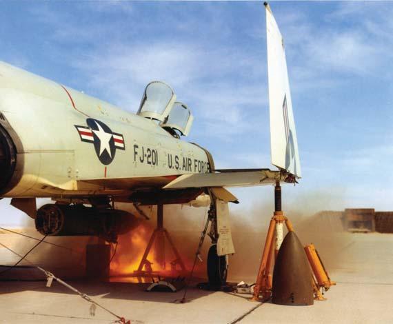
General Electric’s SUU-16/A and SUU-32/A gun-pods satisfied Phantom pilots’ desire for a weapon that would keep heads down ahead of an attack run or provide credible close-in air-to-air shooting power. Remotecontrol range testing of this SUU-16/A involved removal of the rear and lower sections of the pod’s casing, with plenty of restraining cables for the test Phantom. (USAF)
McNamara implemented “flexible response” by seeking a 50 percent increase in the USAF’s tactical airpower. The existing wide range of fighterbombers and light bombers was to be replaced with just two new types, the A-7 Corsair II and General Dynamics F-111, both of which would also be used by Navy squadrons. Because neither of these would be available until at least 1966, he sought a stop-gap fighter-bomber. To McNamara the Phantom II offered both superior performance (proven by the seven world height and speed records attained by F4H-1s by the end of 1961) and also fulfilled his aim of multimission, cost-saving “commonality.” However, despite its obvious qualities, overcoming Air Force preconceptions about buying an aircraft used by a rival service required considerable persuasion by both McNamara and McDonnell’s sales team. In August 1961, two F4H-1s were borrowed for tests at Edwards AFB and flown to Tactical Air Command (TAC) bases by Col Graham and charismatic F-100 wing commander Col George Laven so that USAF pilots could sample the goods. This was followed by an official fly-off competition against TAC’s premier strike fighter, the F-105D Thunderchief, in November 1961. Both types had projected reconnaissance versions in development, which the USAF also required, and both achieved similar results in the set tests, but McNamara’s purposes were best served by selecting the Phantom II.
President Kennedy’s January 1962 budget requested funding for both fighter and reconnaissance versions of the Phantom II. To assuage USAF pride they were initially called F-110A and RF-110A (nicknamed “Spectre”), following the Air Force’s existing “Century Series” fighter designations. To hasten service introduction, 27 more Phantom IIs were reserialed 62-12170/12196 for USAF training and evaluation with the 4453rd CCTW at McDill AFB, Florida. The first aircraft was flown in by Col Stanton Smith on February 11, 1963, by which time McNamara’s September 18, 1962 universal
revision of aircraft designations was in effect and the F4H-1 became the F-4B. In April 1962 the first order for an F-110A (62-12199) was placed with McDonnell, followed on May 29 by another for two YRF-110A reconnaissance prototypes (62-12200 and 62-12201). Like the F4H-1, they received new designations, F-4C Phantom II for the F-110A Spectre and YRF-4C for the recce prototypes.
The first of 583 definitive F-4Cs made its maiden flight on May 27, 1963, and production continued until May 4, 1966. Changes to the F-4B basis were minimal, although TAC was already planning improved ground-attack capability for the type. Some of the first F-4Cs joined the borrowed F-4Bs at McDill AFB, where the 12th TFW became the first active USAF Phantom II wing, achieving operational capability in October 1964.
The USAF’s need for a reconnaissance version of the Phantom in some ways predated its engagement with the F-4C program, and its Specific Operational Requirement (SOR) for the RF-4C was issued in May 1962, three months before a similar SOR for the production-standard F-4C. Its Republic RF-84F Thunderflash and Douglas RB-66 had been in use since early 1954. The RF84F provided relatively short-range, “cameras only” reconnaissance, while the RB-66 carried more sophisticated equipment but lacked the performance and agility to operate over high-threat environments. McDonnell’s own RF-101 Voodoo, in service from 1957, was a short-term solution, offering supersonic performance and longer range, but was equipped only with cameras. In the RF-4C McDonnell was able to combine superior range and supersonic performance with day and night photo-reconnaissance and a sophisticated suite of sideways-looking radar, infrared, and laser-imaging devices.
Two F-4Bs (62-12200/01) were converted into YRF-4Cs (Model 98DF) with an extended camera nose and blanked-off AIM-7 missile wells, and the first was flown on August 8, 1963, only three months after the first F-4C. A fully equipped production version followed in May 1964, and early examples equipped the 4415th CCTS of Shaw AFB’s 363rd TRW in South Carolina that September. The Air Force bought 503 RF-4Cs with deliveries continuing until January 1974, while USMC RF-4B (F4H-1P) production was limited to 46 from 1965, an indication of the way that the USAF took over the Phantom II project from 1964 onwards.
At McDonnell’s St Louis factory, F-4C production increased to 340 per year as 18 TAC wings were progressively reequipped, plus a number of test squadrons and one ADC fighter interceptor squadron, the 57th FIS at Keflavik, Iceland later in the F-4C’s career. The designers’ attention switched to a version that was more attuned to the USAF’s strike roles, the F-4D. Service experience had shown the new fighter to be an exceptional combat aircraft with few vices. Structurally, some cracks had occurred in outer wing panels, and the potting compound used on electrical connectors had proven unsatisfactory and was replaced. Fuel leaks from the wing tanks sometimes necessitated frequent resealing and radars, still relying on pre-solid state technology, required a considerable maintenance effort. Although the F-4 had a far better safety record than its Century Series predecessors, from the aircrews’ viewpoint there were two particular shortcomings. Primarily, there was the “Phantom thing,” a tendency to enter a stall/spin condition if the pilot put too much “g” on the aircraft at high angles of attack, particularly in aerial combat. Spanish F-4C pilots called it the “hachazo” (axe-blow) and it cost them three F-4C crews’ lives. Below 10,000ft there was insufficient time for the aircraft to be recovered from this condition. The solution came
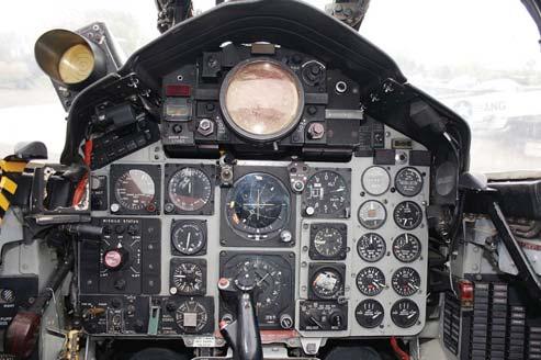
The front instrument panel of F-4C-18-MC 63-7428 at the Minnesota ANG Museum. At the top, centrally, is the radar scope with the attitude directional indicator (ADI or artificial horizon) and horizontal situation indicator vertically below it. The radar altimeter and airspeed indicator are the two larger, circular dials to the left of the ADI and the standard altimeter is to its right. The RWR threat warning indicator is above the left coaming section. (Gary Chambers)
through training, but the second deficiency, the lack of an internal gun, was the result of long-term design policies and was not properly remedied until the F-4E variant was flown in August 1965.
While all-missile armament was appropriate for the Navy’s interception role, TAC could see that USAF ground-attack missions would generate greater need for a gun. Suppression of ground fire, attacks on troop concentrations, and close-in airto-air use could be foreseen in “limited war” scenarios such as Southeast Asia as early as 1963, when interest in an integral gun was first expressed. By 1965, Vietnam experience showed that there was a real need for guns and by October the General Electric M61A-1 rotary cannon, already successful in fighters like the F-104 and F-105, was approved for trial installation in a new Phantom, the F-4E. While this, the most numerous USAF F-4, was developed, an improved F-4C was ordered, although contracts for it had been issued within weeks of the first F-4C deliveries.
The F-4D incorporated changes that brought the Phantom closer to USAF needs without major external changes. Following its Category I acceptance tests in 1966, the usual Category II and III tests were curtailed as the aircraft was so urgently required in Vietnam. In addition to its improved groundattack capability using an ASQ-91 weapons-release computer, it was wired on the production line for the SUU-16/A or SUU-23/A gun-pod, mounted on the centerline. General Electric SUU-16/As had been used in combat, initially by the 8th TFW, as a way of mounting an M61 Vulcan cannon on the F-4 for air-to-ground engagements. It also proved successful in aerial combat, and ten MiGs were destroyed by pod-armed Phantoms over North Vietnam from May 1967. Combat use ended in late 1968. Air-to-air missiles proved to be far from reliable in combat (“miss-iles” rather than “hit-iles,” as one frustrated crewman put it) and pilots welcomed a backup weapon. However, the gunpod was heavy, it used up the 600-gallon tank pylon, its mounting was not sufficiently stable to ensure lasting alignment and accuracy, and its extending ram-air turbine power source limited its use to speeds below 350kts. It also tended to jam.
Mounting the gun internally obviated most of these difficulties, and this had been suggested by McDonnell from 1961 onwards, either as a nosemounted weapon or attached to a rear missile well as a “gun module” containing an M61 and 1200 rounds. Acceptance of the nose-mount location for an F-4E TSF (tactical strike fighter) variant in June 1965 paralleled development of a new radar, the Westinghouse AN/APQ-120(V) (an upgraded AN/APQ-109.) This light-weight, solid-state unit required a smaller scanner, allowing a more pointed nose, extended by 33 inches, and more space to fit the Vulcan cannon and its ammunition drum. At first, engineers used a version that had worked well in the Republic F-105, but the ammunition feed system did not operate properly in the F-4 and redesign was needed. The gun’s
proximity to the aircraft’s radar and other sensitive electronics caused vibration, requiring extensive damping.
A trial gun installation was tested in the YRF-4C prototype 62-12200, replacing the cameras and projecting through the forward/oblique camera window. An AN/APG-30 radar and A4 lead-computing gun sight were fitted for trials as the YF-4E, which also tested prototypes of the J79-GE-10 for the Navy’s new F-4 and J79-GE-17 for the production F-4E. These uprated engines each generated an extra 900lb of thrust and were eventually given a much-needed smoke reduction option. Two more YRF-4Cs were converted, 63-7445 (a former F-4C) and 65-0713 (an F-4D), to refine the gun and radar installations and to establish the correct contours for the nose rather than adapting the flat-sided RF-4C profile. The extra weight in the nose was balanced by an additional 84-gallon fuel tank (number 7) in the rear fuselage. Overall weight reduction was effected by deleting the naval wing-folding mechanism that had been retained in the F-4C/D and the little-used pop-out ram-air turbine that was intended to provide backup generator power. This was later replaced by a small auxiliary power unit in the rear fuselage. Cross-fertilization from the last USN variant, the F-4J, resulted in an improved jet nozzle with longer “turkey feather” afterburner “petals” for the J79-GE-17 engine and a slot on the leading edge of the stabilator, increasing its effectiveness particularly at lower airspeeds.
Production was approved on July 22, 1966 and by June 30, 1967 the definitive F-4E-31-MC (66-0284) was ready to fly, although several items of equipment were not yet installed. One of the principal reasons for the F-4E program was the Hughes CORDS (coherent on receive doppler system), using the APQ-120 radar and Hughes airborne missile control sub-system (AMCS). This advanced system was intended to improve the APQ-120’s performance
A slatted-wing F-4E with six Mk 82s on the centerline pylon, two AIM-9J Sidewinders on LAU-105 rails attached to the right inboard pylon, and a GBU-10 on the opposite pylon. The left forward Sparrow missile well houses an AVQ-23 Pave Spike laser designator pod. MiG-killer pilot Gordon Clouser remarked “I preferred the F-4E. Coming from the F-105 Thunderchief, in my biased opinion any fighter without a gun is not a fighter.” (McDonnell Douglas)
F-4G-43-MC 69-7212 of the 52nd TFW carries an inert AGM-88 HARM in August 1991, although the five “scores” on its intake plate indicate successful live firings during the Gulf War earlier that year. The missile has an adapter beam and the pylon installation is angled slightly outwards to clear the main landing gear. An AN/ALE-40 chaff/flare dispenser is attached to the rear of the pylon. (Author)
against low-flying targets in conditions of “ground clutter,” providing a clearer image for a missile shot against an aircraft as low as 100ft above ground. CORDS ran ahead of the available computer hardware and had to be abandoned in 1968, but a revised APQ-120 was installed in production F-4Es and retrofitted to the first batch of 26 aircraft. Also absent from the first Block 31–33 aircraft was the radar homing and warning (RHAW) system to protect them from enemy SAM (surface-to-air missiles) and other radars. The Bendix AN/APR-107 set originally prescribed for the F-4E proved unreliable and ATI AN/APR-36 and APR-37 units were substituted in production aircraft, with the improved ATI digital AN/ALR-46 system replacing these from the mid-1970s. ALR-46 could be quickly reprogrammed before a mission to tackle threats that might be faced that day.
While all the black boxes were being sorted out, the first F-4E (66-0286) for the 4525th FWW at Nellis AFB was delivered on October 3, 1967 to begin the training program. Other examples reached the first operational TAC wing, the 33rd TFW, at Eglin AFB the following month. By November 1968 F-4Es were replacing the F-105Ds of the 388th TFW at Korat RTAFB, Thailand and flying combat missions over Laos. The F-4E became the USAF’s principal Phantom model and the most widely exported variant. In all, 1,389 were built, of which many were later loaned, transferred, or sold to Greece, Egypt, Iran, Turkey, Israel, Australia, and South Korea. Another 140 were supplied to Japan or built under license by Mitsubishi from 1971 and operated by the
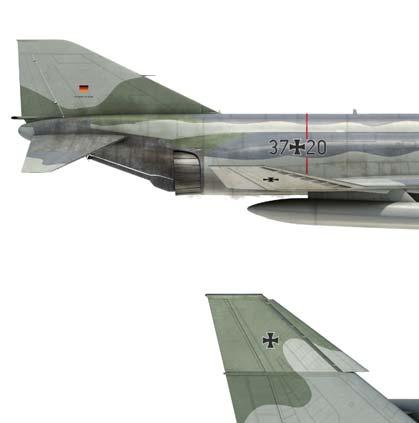
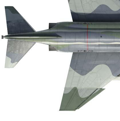
721130, 37+20 OF JG73 STEINHOFF, 1997
The camouflage pattern is Norm 81B using RAL 7012 Basaltgrau, 7009 Grungrau, 7030 Steingrau, and 7037 Staugrau, with 7030 Steingrau and 7035 Lichtgrau undersurfaces. The black radome indicates that the aircraft has received the first two stages of the Peace Rhine/ ICE program, optimizing it for air-to-ground operations for which it would also carry AGM-65 Maverick among other ordnance. JG73 was re-named from JBG35 in 1993 and reestablished at Rostock-Laage AB, operating with former East German AF MiG-29s before converting to the Eurofighter in 2004.


Still wearing civil registration and show number 229 from the 1987 Paris Air Show, Kurnass 66-0327/334 tested the Pratt and Whitney PW1120 turbofan that conferred major improvements in performance, including supersonic speed without afterburner. US disapproval of a potential US-funded competitor for its newer fighters caused withdrawal of the PW1120 option. On museum display, the engineless prototype has the AGM-78 missiles and 105 Squadron markings it used in the 1982 Lebanon conflict. (Author)
Japanese Air Self-Defense Force as the F-4EJ, with 14 RF-4EJ reconnaissance models added in 1974. West Germany ordered 150 RF-4Es and 175 F-4Fs, a modified F-4E with part-manufacture of the airframes and license-building of the J79-GE-17A engines undertaken by German firms. All these countries invested heavily in the F-4E, and it has been the subject of numerous update programs to extract the longest possible service life from each airframe.
In USAF service the F-4E received a number of improvements in the light of combat experience in Vietnam. As a missile-armed interceptor the F-4 was never intended to engage in close combat with enemy fighters, yet over Vietnam there were frequent fights with more agile MiG-17s, MiG-19s, and MiG-21s. While Phantom crews had maintained an acceptable degree of superiority over these adversaries, it was clear that a more maneuverable F-4 would increase the kill rate in combat and also reduce losses through stall-spin “departures” in high-g maneuvering, which caused the loss of almost 200 F-4s in all. From 1958 onwards it had been suggested that slats on the leading edges of the wings of land-based F-4s could replace the blown-flap system that had been installed to improve the naval Phantoms’ low-speed handling for aircraftcarrier recovery. Studies at McDonnell Douglas (the two firms merged in 1967) had been undertaken in the early design phases for the F-4’s successor, the F-15 Eagle, although in the end slats were not required for the new fighter.
Once again, McDonnell’s test-bed Phantom 62-12200 was enlisted, and it was fitted with maneuvering slats in 1969. Supporting trials in Israel with a similarly modified F-4E showed that the stall-spin condition could be abated in hard turns, and combat maneuverability was improved though top speed fell by 80kt. After various slat configurations had been tested in the Agile Eagle 1 and 2 initiatives, a definitive slat arrangement was installed in F-4E 66-0287 using hydraulically powered slats on both outer and inner wing panels. F-4Es from aircraft 71-0237 in production block 48 onwards had slats installed “on the line” and retrofit kits were supplied to modify 304 F-4Es with the original “hard” wing.
Although McDonnell Douglas built reconnaissance versions of the F-4E as the RF-4E for an offset sales agreement with Germany, no funding was
available to replace the USAF fleet of RF-4Cs with the more fuel-efficient J79-GE-17-powered RF-4E. However, one final major evolution of the F-4E design was allowed when 116 USAF F-4Es were converted to F-4G “Wild Weasels.” Soviet SA-2 Guideline air-to-ground missiles proved to be deadly adversaries for US air forces in Vietnam, shooting down 195 aircraft and requiring a considerable effort in devising adequate countermeasures. SAM-suppression equipment was operationally tested in F-100F Super Sabres and then installed in F-105F/G Thunderchief “Wild Weasels,” which achieved considerable success with their electronic countermeasures and specially developed antiradiation missiles. As F-105 production had ceased in December 1964 in favour of the F-4D, it was clear that losses of F-105 Wild Weasels would have to be met by a Phantom conversion. The first attempt was a batch of 36 Wild Weasel IV F-4Cww or “EF-4C” conversions in 1968, but the aircraft’s dense internal structure precluded the effective installation of the necessary electronics, including provision for the AGM-78, the most effective of the available anti-SAM weapons.
F-105Gs (Wild Weasel IV) and EF-4Cs provided SEAD (suppression of enemy air defenses) during the final stages of the Vietnam War, but the quest for a Wild Weasel V received a major boost in 1973. Over 30 Israeli Air Force Phantoms were destroyed by Soviet SAMs and radar-directed ZSU-23 AAA (antiaircraft artillery) during the brutal Yom Kippur conflict that autumn when American ECM equipment in the Israeli aircraft provided insufficient protection. McDonnell and IBM had tested a new homing and warning computer, the AN/APR-38, in two F-4Ds in 1973 but internal space limitations prevented adequate installation. Attention turned to the F-4E, but even there the only viable installation area was to be found by removing the M61 gun, with other components in a fin-top pod. This proposal was successfully tested in F-4E 69-7254, and 134 F-4Es were subsequently converted to F-4Gs. The aircraft gained AGM-78 Standard ARM capability and it could still handle all the F-4E’s external ordnance. It entered squadron service in April 1978. Together with General Dynamics EF-111A Raven and USN EA-6B Prowlers, the USAF’s F-4Gs led the Operation Desert Storm air campaign in 1991, speedily disposing of Iraq’s air defenses. This F-4G force was living on borrowed time though. Its retirement was delayed by participation in the first Iraq war, but six years later the final combat sortie was flown on January 2, 1996. Retirement from active service for these, the last USAF Phantoms, was signaled by the final sortie by an Idaho ANG F-4G on April 20 of the same year, 34 years after the first USAF funding was allocated for the F-4. Whereas 1950s fighter aircraft were expected to last for a few years before being replaced, the F-4 showed that in an age of far more costly warplanes a sound design could be updated and adapted to new roles, still holding its own alongside more recent types. Service life extension programs (SLEP), such as those for Japan’s F-4EJ Kai, Israel’s Kurnass 2000, Germany’s F-4F ICE, and Turkey’s Phantom 2020, have combined advanced digital electronics developed for a later generation of fighters like the F/A-18 Hornet with refurbished F-4 airframes. This has enabled the Phantom to handle a wider range of guided weapons, such as the AIM-120 AMRAAM missile, using more powerful and reliable radars and fire-control systems. Many of these projects have been undertaken by foreign Phantom users, as McDonnell Douglas, from the 1970s onwards, wanted to promote its new products such as the F-15 Eagle and F/A-18 Hornet. In 1967 the company did draft a radical, short-lived proposal for a swing-wing F-4J (FV)S as an alternative to the
Grumman F-14 Tomcat. However, Boeing Military Airplane Company (BMAC), which merged with McDonnell Douglas in 1997, proposed another “Super Phantom.” Reengined with Pratt and Whitney PW1120 turbofans, this F-4E derivative had a 1,100-gallon conformal fuel and weapons tank beneath most of the fuselage, and avionics drawn from the F-16, F/A-18, and Northrop F-20 programs. The PW1120 was installed in a demonstrator and it generated 30 percent more afterburning thrust and weighed 25 percent less, with a potential 18 percent range increase. Although the engine promised spectacular performance improvements, this proposal failed to find customers and funding was terminated in 1986.
TECHNICAL SPECIFICATIONS
Airframe
Fuselage
Aircraft carrier operations required a strong, resilient airframe and the USAF Phantom variants all benefited from its naval origins. During the eight-month building process the fuselage was constructed in three sections. The forward fuselage was split vertically, with most of the wiring and ducting inbuilt before the halves were joined. It included the forward air intake ducts, their ramp actuators, and rigid, machined intake leading edges. The perforated forward ramp let boundary layer air bleed off and exhaust overboard, while its solid rear section was positioned by the air data computer to provide optimum airflow at high speeds. Tandem, pressurized cockpits with two Martin Baker Mk H5 ejection seats (later replaced by the Mk H7 rocket-powered, zero-zero model), the nose undercarriage well, and the Number One fuel cell occupied most of the space, together with denser structures including the radar, cabin air-conditioning, oxygen system, and other avionics. Re-contoured noses, extended by 4.75ft, housed the reconnaissance equipment for the RF-4 versions or the gun for the F-4E/F. The radar scanner, 32 inches in diameter in the F-4C/D but smaller for RF-4/F-4E variants, was housed in a neoprenecovered fibreglass radome.
In the 22ft-long centre section were the two engine compartments with a central dividing keel, six fuel cells (five in the F-4C/D), and access doors for the engines and fuel system. Whereas the forward fuselage was mainly aluminum, a variety of alloy, titanium, and stainless steel components coped with the high temperatures in the central fuselage. The rear fuselage (mostly made by Republic Aviation Corporation) supported the three-spar vertical fin and rudder and the one-piece horizontal stabilator. The latter, with 35 degrees sweepback and 23.25 degrees anhedral, had titanium inner sections to resist the heat from the engine efflux passing directly beneath it. Its drooped configuration provided good longitudinal and directional stability and counteracted the upswept outer wing panels’ tendency to make the aircraft roll during a yawing maneuver. Its location saved structural weight in the vertical fin compared with the high-mounted position McDonnell had used for their F-101 Voodoo, and it prevented the stabilator from being “blanked off” by the wing at high angles of attack. It also acted as an air-brake if fully depressed after touch-down on landing.
Stabilator and rudder operation used a traditional system of push/pullrods, bell-cranks and cables, with a stall warning mechanism that vibrated the
pilot’s left rudder pedal. An aileron/rudder interconnect (ARI) moved the rudder proportionately to the ailerons, allowing smooth, coordinated turns at lower airspeeds. The rudder became effective at about 70kt on take-off. A compartment at the end of the fuselage housed the 16-foot ring-slot brake parachute, deployable below 200kt. The lower keel area between the jet-pipes comprised a double-wall structure with innovative titanium skins, asbestos insulation, and ram-air cooling protected by an additional layer of titanium shingles. All F-4s had the naval arresting hook attached to the central fuselage keel area, actuated by hydraulic pressure.
Wing and flight controls
The basic F-4 wing was a multi-spar structure with 45 degrees of sweepback. A torque-box structure, extending outwards to the wing-fold line where the outer panels were attached, was sealed to form a fuel tank. Canted upwards at 12 degrees, each outer panel folded upwards, another inherited naval characteristic. The skins for this wing-box were expensively milled to taper from the wing-root outwards as a weight-saving measure. Hydraulic threeposition flaps were attached to the trailing edge of the inner wing section. Ailerons fitted outboard of the flaps were synchronized with two spoilers above each inner wing section. The ailerons deflected fully down by 30 degrees individually but upwards by only 1 degree, while the spoilers could rise up to 45 degrees, so that in order to bank to the right, the left aileron was depressed and the right spoiler was raised. With flaps lowered the ailerons both automatically depressed by 10 degrees, but continued to behave as ailerons. For take-off the pilot selected “HALF” on his flap lever, dropping the leading edge flaps by the full 60 degrees and the trailing edge flaps by 30 degrees. Flaps and slats tended to “chatter,” or vibrate on extension, maneuvering, or retraction, audible as brief electronic interference on the pilot’s headphones. On “hard-wing” (unslatted) Phantoms, “HALF” also engaged BLC (boundary layer control) for the leading edge flaps. The “DOWN” position

While “wonder arch” shelters are constructed to protect aircraft from Viet Cong rocket attacks, RF-4C-25-MC 65-0840 sits in an open 12th TRS revetment. The squadron flew combat missions from Tan Son Nhut AB from 1966 to 1971. Ahead of the all-moving, unslotted stabilator with its heat-resistant titanium inner section, the closed doors of the photoflash cartridge ejectors can be seen. The outboard ailerons (or, more accurately, “flaperons”) drooped without hydraulic pressure. (USAF)
General Electric’s J79 engine was produced for over 30 years in various, similar versions for the F-4, F-104, B-58A Hustler, A-5 Vigilante, F11F-1F, IAI Kfir, and in its J79-119 version (with a sharper “bullet” fairing) for the GD F-16/79. Modular construction simplified maintenance. GE boasted that early J79s sustained less than one in-flight shutdown problem per 100,000 flight hours. (General Electric Company)
on the flap control, used for landing, also set the trailing edge flaps at 60 degrees and switched in their BLC too. The BLC system, deleted for the F-4E/G, drew hot air from the 17th compressor stages of both engines, piping it out over the flaps and giving the effect of improved air-flow over the wing and lower stalling speed. A hinged, hydraulic speed-brake opened below each wing, operated by two switches on the throttle control. In wartime, antiradar chaff could be dropped from the speed-brake wells. There were two pylon hard-points on each wing.
Three separate hydraulic systems operated at 300lb psi: PC1 and PC2 to power the ailerons, stabilator and spoilers via a pump attached to each engine, and a utility system to power flaps, undercarriage, rudder, wing-fold (where applicable), arresting hook, and nose-wheel steering. Despite the mutual backup arrangement of the three systems, hydraulic failure, particularly after combat damage, was a common source of lost F-4s. However, a further emergency pneumatic system provided backup power to the flaps, undercarriage, and wheel brakes if the hydraulics failed. The inward-retracting main undercarriage wheels had tires inflated to 200 psi.
Engines
With a production run of over 17,000 units, the General Electric J79 was one of the most successful turbojet engines of its time and its designers won the 1958 Collier Trophy. Aircraft using the engine set 46 new world performance records and it remained in production for over 30 years. License production of 3,249 for overseas users of the F-4 and F-104 Starfighter was undertaken by Bet Shemesh Engines in Israel (also for the IAI Kfir fighter), MTU Aero Engines in Germany, Ishikawajima-Harima Heavy Industries in Japan, Orenda Engines in Canada, and a consortium of Alfa Romeo, Fiat, and Fabrique Nationale in Europe. Weighing 3,850lb, the 19ft 4inch-long powerplant offered light weight and up to 17,900lb of afterburning thrust. Its single-spool turbojet design, including a 17-stage compressor with costly stainless steel blades, was innovative in using stator vanes whose angle could be varied
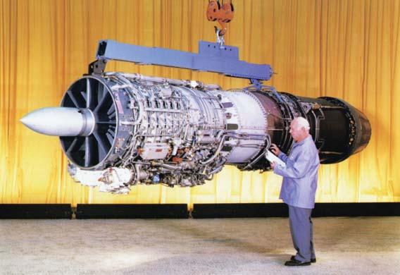
according to the aircraft’s angle of attack. This enabled the engine to develop as much thrust as a twin-spool engine but with lower weight and complexity and reduced compressor stalling. The J79 opened the way for a whole generation of high-thrust, low-weight engines.
A major component in the successful combination of J79 engine and F-4 airframe was the very effective air intake system. McDonnell designed one of the first variable geometry systems, using ramps that varied the intake crosssection to control the speed and volume of airflow and a perforated bell-mouth ring ahead of the compressor, regulating the amount of air that bypassed the engine and reducing a build-up of air and consequent stall. Smooth airflow and controllable pressure were therefore maintained for air entering the engine. As hot gases passed through the engine and afterburner section, where they were mixed with raw JP4 fuel to give a massive thrust increase, they also passed through McDonnell’s convergent/divergent jet nozzles. At that point the jet efflux was mixed at the “convergent” nozzle (the inner “ring” of the rear engine as seen from behind the aircraft) with bypass air that had flowed around the engine giving additional cooling. Gases then passed through the “divergent” nozzle (the outer part of the tail-pipe), which controlled the speed of the air-mass as it left the aircraft. The volume of cooling air drawn into the jet efflux was sufficient to prevent the afterburner heat from damaging the engine casing. Afterburners could be modulated through four stages of extra thrust, a big advance on the “on/off” afterburners of earlier fighters.
The engine oil tank held 6 gallons, burned at about one pint per hour. In combat, the engine’s main disadvantage was its dense smoke-trail, visible from up to 20 miles. It could be reduced by using minimum afterburner on one engine and “idle” power on the other in cruise flight. A minor upgrade that increased burn temperature by about 10 degrees could eliminate the smoketrail, but this reduced engine life and was seldom installed.
Fuel system
The F-4C’s six fuselage tanks held 1,342 gallons of JP4 with another 630 gallons in two internal wing tanks. Additional avionics in the RF-4C and F-4D occupied some No 1 fuselage tank space, reducing overall fuel capacity to 1,259 gallons. The F-4E added a seventh fuselage tank but other reductions in tank size kept overall fuselage capacity to 1,225 gallons. A further 600 gallons were available in an external Royal Jet tank below the fuselage (a “ferry” tank that wasn’t stressed for combat) and 740 gallons in two McDonnell or Sargent Fletcher external wing tanks, each cleared for Mach 1.6. Exact sequencing of the fuel transfer from all these tanks was necessary to preserve the center of gravity. Emergency fuel dump vents were located on each wing trailing edge. Fuel consumption averaged 190lb per minute, increasing to around 750lb per minute in afterburner.
Armament
Air-to-air missiles and guns
Raytheon/General Dynamics AIM-7 Sparrow III. The Phantom was originally designed around this missile, used by all F-4s excluding the RF-4C/E, with two or four carried in purpose-built fuselage wells. Originating from earlier Sparrow air-to-air missiles dating back to 1946, the AIM-7E was the first mass-produced version in 1963 and the main armament for the original F4H-
The breech door for the F-4E/ F’s Vulcan gun, opened with two quick-release fasteners and left open preflight to check that a gun safety pin (visible here with its red ribbon) was in place. Other panels revealed the whole gun for maintenance purposes. Above the gun breech is the air scoop for cooling the avionics and cockpit environmental control system. (Author)
1. It was designed to hit large, non-maneuvering targets at high altitude. Widely used with disappointing results in very different circumstances in Vietnam, it was succeeded by a “dogfight” version in 1969, the AIM-7E-2, which had shorter minimum range and improved maneuverability. The AIM-7F, with a bigger warhead, longer range, and a Doppler seeker head, entered service in 1975 aboard F-4E/G Phantoms and was succeeded in 1982 by the AIM-7M with further warhead improvements and a digital monopulse seeker that could avoid locking on to flares ejected by a target aircraft to distract the missile. The AIM-7E weighed 452lb, achieved a peak speed of Mach 3.7, and had a range of up to 28 miles, though rocket burn time could be reduced to around 5 miles in denser, low-altitude air. Its 66lb warhead exploded into 2,500 destructive fragments. Guidance was by a Raytheon continuous wave, semiactive radar linked to the F-4’s search radar, which had to “illuminate” the target from missile launch until impact or the radar lock would be broken and the missile would go astray. It was replaced on F-4F ICE and Greek AF Peace Icarus 2000 F-4Es by the Hughes AIM-120 AMRAAM with lighter weight and greatly improved performance.
Ford Aerospace/Raytheon AIM-9 Sidewinder. Used by all F-4s including some RF-4Cs and developed from 1951 onwards, the short-range, heatseeking AIM-9 was the USAF’s most successful air-to-air weapon in combat. The first operational version, the AIM-9B, had a 2.6-mile range, a 10lb blastfragmentation warhead, and 155lb weight, but it could only be fired from directly behind a non-maneuvering, heat-emitting target, unlike later models. Later USAF versions (also used by foreign air forces) were the AIM-9E with a more sensitive Peltier thermo-electric cooler, the AIM-9J with double-delta fins, and the AIM-9L all-aspect version. The AIM-9M and AIM-9P were improved AIM-9Ls, and many of them upgraded earlier missiles as well as new-build. Late AIM-9 variants offered a five-fold range increase over the AIM-9B.
General Electric M61 Vulcan 20mm gun. This was used by F-4E/Fs (internally) with 639 rounds of M50 ammunition and in an SUU-16/A or
SUU-23/A external pod with 1,200 rounds by the F-4C/D. Its six, 5ft-long barrels rotated anticlockwise as a unit, reducing heat and increasing barrel life. Rate of fire was selectable at “low” (4,000) or “high” (6,000 rounds per minute), and the pilot could select a set number of rounds (typically 50) per burst, up to a limit of 3 seconds’ firing time to prevent over-heating. Total firing time at 6,000 rounds per minute was about 13 seconds for the internal gun. Electronically primed rounds were drawn from an internal drum (or storage at the rear of the pod) via a linkless feed on a flexible conveyor belt. Spent cases were returned to the drum to preserve the center of gravity.
Hughes AIM-4 Falcon. Dating from 1949, the GAR Falcon family evolved into the AIM-4D (GAR-2B) by 1963. This heatseeking, short-range alternative to the AIM-9 was used by several USAF interceptors and some F-4D/Es. Its complex setup and cooling procedure caused problems for combat use in Vietnam.
Rafael Armament Authority Python 3. An Israeli AIM-9 derivative used from 1977 onwards, this heatseeker with a thermo-cooled IR (infrared) seeker had larger, swept-back tail fins, Mach 3 speed, a 31lb warhead, and all-aspect capability comparable to the AIM-9L.
Air-to-surface guided weapons
Martin Marietta AGM-12 Bullpup. The widely used AGM-12B of 1960 was a redesign of the 1954 ASM-N-7A stand-off, rocket-propelled guided bomb, with a 250lb warhead and a range of 7 miles. It was superseded in 1964 by Bullpup C (AGM-12C) with a 1,000lb warhead. Controlled by a small joystick in the cockpit, the missile had tail-mounted flares for the pilot to guide it visually, but this required him to risk flying directly towards the target until bomb impact.
Hughes/Martin Marietta AGM-62 Walleye. This early glide-bomb was controlled by a nose-mounted TV camera, gyro-stabilized to lock on to a high visual contrast target and allow the carrier aircraft to leave the area, having dropped it from around 35,000ft. It was used by USAF F-4D/Es and Israeli F-4Es. Walleye II was based on a 2,000lb Mk 84 bomb.
Two AIM-7E Sparrows occupy the rear missile wells on this F-4D-33-MC (66-8796) in 1968, while the left forward well houses a Fairchild KB-18 70mm panoramic strike camera for bomb damage assessment. The inboard pylons each hold three SUU41/A “Gravel” dispensers (used by the 8th TFW), with ten cluster weapon adapters per pod. “Gravel” mines, including the CBU-39/A, CBU40/A (antipersonnel), or ten CBU-5/B clusters with a total of 7,500 XM40EJ antiintrusion mines per dispenser, were loaded. (Al Piccirillo via Norman Taylor)
A formidable warload of Mk 82 bombs, AIM-7E missiles, and a 571lb AGM-12B Bullpup air-to-ground missile. The “AWOL” nickname on F-4D32-MC 66-8727’s flank indicated the “absence” of its MiG-killing pilot Capt Doyle D. Baker from the US Marine Corps while he was attached to the 13th TFS at Udorn RTAFB in 1967. Guidance flares can be seen at the rear of the missile. (Col Doyle Baker via Peter B. Mersky)
Hughes AGM-65 Maverick. This Bullpup-replacement project, begun in 1965 for service in 1972, included the TV-guided AGM-65A/B and AGM65D/G with imaging infrared guidance for night-capability, doubled lock-on range, 300lb warhead, and compatibility with the F-4G’s APR-38 system. It was also used by the F-4F and F-4Es of Turkey, Israel (as the “Penguin”), and Greece. Effective range is 8–9 miles.
Rafael Armament Authority/Martin Marietta AGM-142A Popeye. Weighing 3,300lb, this stand-off missile required a special inboard pylon adapter and an AN/ASW-55 data pod on the outboard pylon. It was also cleared for Turkish F-4 “Terminator 2020s” and some RoKAF F-4Es.
IMI Gabriel Mk IIA/S. An air-launched, transonic version of an Israeliproduced, sea-skimming, antishipping missile with a 330lb warhead and 25-mile range. Guidance was either fire-and-forget via its own agile radar, through radar control from the launch aircraft, or via datalink from a helicopter. Two of these 12.6ft-long missiles could be carried by Israeli F-4Es.
Texas Instruments AGM-45A Shrike. A US Navy-developed 400lb antiradiation missile, tuned (premission) to particular radar emitters that it could damage or destroy with a 145lb warhead at around 8–15 miles’ range. It was used by USAF F-4G, F-4Cww, and Israeli AF F-4E.
ORDNANCE/ARMAMENT
1. Rockwell KMU-353A/B (GBU-8/B) HOBOS
2. Ford Aerospace/Raytheon AIM-9L Sidewinder
3. General Electric AN/ALQ-87 ECM pod
4. Rafael Shafrir 2 missile
5. Raytheon/GD AIM-7E-2 Sparrow
6. Hughes AIM-4D Falcon missile
7. Marconi/Tracor QRC-490 chaff dispenser
8. SUU-30/B CBU dispenser
9. Westinghouse AN/ALQ-119(V) ECM pod
10. General Electric SUU-16/A gun-pod
11. Hughes AGM-65B Maverick missile
12. Texas Instruments/Raytheon GBU-12/B
13. Mitsubishi Type 80 ASM-1 missile
14. Hunting Engineering BL755
The inboard pylon of a JaboG35 F-4F, with training rounds for the AIM-9 Sidewinder and AGM-65B Maverick. The “scene mag” stencil indicates that the missile’s TV guidance system includes a facility to magnify a target image on a cockpit screen, allowing the pilot to see and lock on to smaller targets at greater range, albeit with a rather small field of vision. (Author)
Armed for virtually any eventuality apart from “air-toair,” 81st TFW F-4D-31-MC 66-7735 totes a Rockwell GBU-8/B HOBOS (left). The centerline pylon supports an SUU-23/A gun-pod and the right inboard pylon has a GBU-10 laser-guided bomb. The forward missile wells accommodate an AVQ-23 Pave Spike (left well) and an ALQ-119(V) ECM pod (right, foreground). (Author)
General Dynamics AGM-78 Standard ARM. Originally, it used Shrike guidance electronics attached to a USN RIM-66 Standard surface-to-air missile, but was airlaunched to perform the Shrike function more effectively at up to 50 miles’ range with a 214lb warhead. The upgraded AGM-78C/D had new guidance electronics. It was used by USAF F-4Gs and the Israeli Air Force.
Texas Instruments AGM-88A/B/C HARM. A sophisticated replacement for Standard ARM, it was faster, lighter, and had a “broad band” seeker that could be programmed against several SAM sites, either from the F-4G’s APR-47 radar warning receiver or before flight when the missile searched out its target, guiding onto the target’s emissions. A third mode enabled it to home on to unanticipated targets of opportunity.
Mitsubishi Type 80 ASM-1C. This 1,345lb medium-range antishipping missile was compatible with the F-4EJ Kai. Powered by a solid-propellant rocket motor, this “fire-and-forget” 684mph weapon combined inertial and radar guidance.
Bombs
F-4s of many air forces have carried a wide range of general-purpose, free-fall bombs including M117 (820lb), Mk 81 (260lb), Mk 82 (510lb), Mk 84 (1,972lb), and retarded versions of the Mk 81 and Mk 82 with extending Mk 15 Snakeye 1 fins. Air-inflatable retarding kits could also be fitted to the Mk 82 AIR, M117 AIR, and Mk 84 AIR. Spanish F-4Cs also carried indigenous ALD-250 and ALD-500 versions of the Mk 82 and Mk 83, among others.
After tests with many different versions, laser-guided adaptations of the Paveway I series GBU-12 (Mk 82-based) and GBU-10A/B (Mk 84) were used in Vietnam by F-4D/Es, and were succeeded by the Paveway II with simpler guidance electronics and pop-out wings that occupied less space than the fixed aerofoils of Paveway I. Paveway III versions of the Mk 84 (GBU-24/B), introduced in 1987, had a digital autopilot and microprocessor controls for
use in poor weather and for release at low altitude or in a zoom-climb. The Israeli Aircraft Industries’ Griffin and Guillotine were Paveway derivatives, but Israeli F-4s also used GBU-10 and GBU-12A/B (known as Zar’It 82) and the Elbit Opher infrared homing and control package for bombs including the Mk 82.
Laser guidance for Paveway bombs came from a series of designator pods, beginning with the so-called “Zot Box” attached to the rear canopy of 8th TFW F-4Ds in the late 1960s (also to some Iranian AF F-4Ds). Several F-4Ds combat-tested the heavy AVQ-10 Pave Knife designator, which housed laser and low-light TV designators and was intended to work with the aircraft’s radar. Other systems, including AVQ-11 Pave Sword, were also tested, and AVQ-23 Pave Spike, using a similar Pave Knife-type TV system in a much smaller pod, became widely used as a daylight-only laser designator for USAF and some South Korean and Turkish AF F-4D/Es. AVQ-26 Pave Tack, the first night-capable laser designator, was mainly associated with the F-111F Aardvark, but some F-4Es were also equipped with it.
Vietnam was the proving ground for a range of electro-optical precisionguided munitions. The first operational model was the Rockwell homing bomb (HOBOS/GBU-8), using the Mk 84 bomb and GBU-9 with a 3,000lb M118E1. An F-4 back-seater locked the launch-and-leave bomb onto a target, and the weapon’s KMU-353/A (Mk 84) and KMU-390/B (M118) imagecontrast seeker systems guided it on its trajectory. An alternative guidance kit, the KMU-359/B that used infrared imaging, was tested. These weapons were also used by Israeli F-4Es, and they evolved into the GBU-15 Modular Guided Weapon with larger aerofoils to increase range. Like earlier GBUs it used a strap-on guidance package and fin kit attached to a standard bomb, in this case a Mk 84, with datalink control.
Initially, cluster bombs were dispensed from containers (e.g. SUU-7) that remained on the F-4’s pylons, but for greater accuracy and reduced drag, freefall dispensers (e.g. SUU-30) that open out and disperse the “bomblet” submunition contents (e.g. BLU-26/B or BLU-43/B) were devised instead. They were extensively used for tasks ranging from antiaircraft site suppression to
An F-4G with a full complement of SEAD weaponry, including AGM-88B HARMs and AGM-65G Mavericks on LAU-117 launchers, with a pair of AIM-7F Sparrows in the rear wells in case the bad guys appear. A high-g F-15 centerline fuel tank and an AN/ALQ-184(V)1 ECM pod complete the lethal load. (USAF)
Another random document with no related content on Scribd:
The lighter shades of yellow chrome are made by a cold precipitation process, or (as is usual for the deeper shades of chrome, orange, and red) by boiling the ingredients—lead acetate, pulp white lead, bichromate of potash and soda, and sulphate of soda—while barytes is added as the colour is being made. Danger in the first method does not arise (or only in minor degree when steam is injected to bring about more speedy solution) until drying and grinding (in edge-runners), sieving, and packing, are effected. The dust, when inhaled, is quickly absorbed, and in all these dry processes danger, in the absence of very carefully thought out exhaust ventilation, is great. In processes involving ebullition, danger is present in the steam which carries up with it chromate of lead in fine particulate state. Vats and vessels, therefore, in which the boiling is effected require partial hooding over and connection of the hood with an efficient exhaust. In subsequent wet processes of pressing the cakes of chromate of lead, the hands, arms, and overalls become thickly coated with pigment. Danger from chrome greens is practically limited to the dust created in dry grinding, usually effected in large edge-runners.
For references, see end of Chapter XVII.
CHAPTER XVII
DESCRIPTION OF PROCESSES—
Continued
Coach-Painting.
[34]—Lead poisoning is peculiarly prevalent in this industry, and no corresponding reduction in the number reported can be observed from year to year (see the table on p. 47), or in the many industries grouped under the heading, “Paint used in Other Industries,” such as is noted for lead industries taken as a whole.
Of the 697 cases included in returns during the ten years 19001909, 352 were reported from railway carriage and waggon works, 299 from ordinary carriage works and wheelwrights’ shops, and 46 (separate tabulation was only commenced in 1905) in motor-car works. In the year 1903 inquiry was made in 603 factories and workshops, including all classes of coach and carriage building, railway carriage and engine works, and agricultural implement works. Information was asked (among other things) as to—(1) The number of persons employed in painting with lead paints; (2) description of the method adopted for smoothing the coats of paint; and (3) the substitutes tried for white-lead paint. Persons employed numbered 9,608. In 52 factories and workshops smoothing of the coats of paint was not practised, while in the remaining 551 it was affirmed that a wet method alone (pumicestone and water) was used in 178, a dry method alone (sandpaper) in 39, and both wet and dry methods at some stage or other of the work in 334. Substitutes were mentioned as having been tried in 94 instances, but this was almost exclusively for filling and jointing, and not for the first or priming coat.
The figure 178 (wet method alone) is probably much too high, because, while it is true that pumicestone and water alone are used for the flat surfaces of the body—the bulk of the work—dry sandpapering of the first two priming coats and of the final finishing coats (when of white, cream, or yellow colour), of the under parts of
carriages, iron chassis of motor-cars, and of curved surfaces, such as the spokes of wheels, is almost universal. The reason for thus treating the priming coat dry is that a wet process would raise the grain of the wood. The 52 factories in which it was stated that no smoothing was done were nearly all premises for the repair or manufacture of railway trucks, requiring no special finish, and the 39 factories in which only sandpaper was said to be used in smoothing were premises in which rough, cheap, or common vehicles, such as carts, were made. Use of sandpaper is quicker and less expensive than use of pumicestone, and water and wet methods cannot be used very well on iron surfaces.
In ordinary coach and carriage painting, after the sandpapering of the first two priming coats, six or seven coats of “filling” (usually ground slate mixed with gold size and turpentine) are applied, and each coat is rubbed down wet. Joints and interstices of woodwork and irregularities in iron surfaces are generally filled in with a stopping or paste of white lead, in the smoothing of which sandpaper is used.
In the manufacture of motor-cars, the terne (lead) coated sheets which form the body, after preliminary preparation, receive two coats of a lead paint. These are either lightly sandpapered or “flatted” with pumice and water. Three coats of non-poisonous filling follow, and are flatted with pumice or German brick and water. The body then passes to a skilled workman, who applies the final coats of colour. For facing mouldings and for corners throughout all stages of the processes, dry sandpaper takes the place of pumice and water. All stopping on the chassis, the first lead coat on the bonnet, and all coats of paint on the wheels, are sandpapered dry. Sometimes a third of a man’s time may be taken up in sandpapering alone.
Dangers and Prevention.
—Grave risk of inhaling lead dust is present (see the table on p. 47) when sandpaper is used, often at a point just above the mouth and nostrils. Rubbing down the wheels is perhaps the most dangerous work, and for this exhaust ventilation can be applied locally. Inventive genius has yet to be directed to some modification of the vacuum-cleaning apparatus, so that an exhaust can be attached to the back of the worker’s hand or in connection with a frame in which the sandpaper is held. In the
process of wet rubbing, the abraded coats drip on to the floor, and when dry may rise as dust into the atmosphere.
Precisely similar operations, or only modified in detail, have accounted for heavy incidence of lead poisoning in the painting of perambulators, of safes, of bicycles, of bedsteads, of gas-meters, the “metallic” enamelling of baths (in which also chipping off of the old paint not infrequently occasions an attack), in engineering and machine-making works, in cabinet and furniture making, in French polishing, in the making of artists’ canvases, etc. Several cases are reported among railway employees engaged in the painting of bridges, girders, and signal-posts. A method for the removal of the dust given off in these processes has not yet been arranged. Chipping off of old paint can be effectually replaced by solvent solutions, in the use of which, as they are very inflammable, precautions against naked lights are necessary.
In the making of better-class measuring tapes, the tape, after passage through the white-lead mixture and drying, is made to travel through a machine to remove roughnesses, and subsequently through the fingers of the worker, protected by leather. Dust arises in both the last operations, and requires to be removed by exhaust ventilation. Similar means of prevention are necessary wherever paint is applied, as in photo-engraving, and colouring artificial flowers by means of an aerograph instrument.
Owing to the limited extent to which exhaust ventilation is possible, reliance must be placed on substitution of wet processes for dry wherever possible. Cleanliness of floors requires special attention. Although in all painting operations dust is the most potent cause of poisoning, we would assign to contamination of the hands and the eating of food with unwashed hands a more prominent place as a cause than in any of the other processes involving use of lead or lead colours. In a post-mortem on a sign-painter employed only a few days, made three weeks after his cessation of employment on account of an attack of encephalopathy, paint was found thickly adherent under the nails.
Substitution of colours containing no lead suggests itself as a simple remedy, but the progress in this direction made so far in the industries mentioned is limited. Several important firms
manufacturing motor-cars use no lead colours at all; more than one important railway company (the outside of the carriages of which has no white colour) and a few makers of perambulators do the same. It is difficult to obtain knowledge how far leadless are replacing lead colours. In the manufacture of cornice poles (in which small industry several severe attacks were reported) the suggestion of a factory inspector to employ lithopone was adopted, with entire success. A patent graphite has been substituted for orange lead, with which wooden patterns to form the moulds of articles to be subsequently cast in metal are frequently painted.
House-Painting.
[35]—The work of house-painting and plumbing outside a workshop does not come under the Factory and Workshop Act, 1901, except to a limited extent under Section 105 in buildings in course of erection; and even in that case the requirement of notification of lead poisoning imposed by Section 73 does not apply. If, however, a house-painter is employed for part of his time in mixing paints in a workshop belonging to a builder, then the question may legitimately be raised as to whether plumbism may not have been due in some measure to such workshop conditions. Despite the limited extent to which the Act applies to lead poisoning of housepainters and plumbers, seeing that it is industrial in origin many practitioners notify cases, with the result that the number every year exceeds considerably that from any other lead industry in the country. Thus, the number notified in the ten years 1900-1909 was 1,973, including 383 deaths. The proportion of deaths to persons notified is much higher than for lead industries generally (19·4 per cent., as compared with 4·0 per cent.). If the proportion of cases to deaths were the same in house-painting as in other industries (and it is a fair assumption to make), the number of cases would be 9,418. When investigation is made into the reported cases, the predominance of the severer symptoms—paralysis, brain symptoms, and chronic plumbism—is brought out. Causation of poisoning, in order of importance, appears to be: (1) Dust from sandpapering one surface of paint before applying another; (2) dust from mixing dry white lead with oil; (3) dust arising from paint that has dried on overalls; (4) contamination of food with unwashed hands; and (5) fumes from burning off old paint.
Use of Leadless Paints.
—Opinion still differs as to the feasibility of substituting zinc sulphide or zinc oxide (or a combination of the two) for white lead in paints, in spite of elaborate investigation of the point by commissions of inquiry appointed notably by the French, Austrian, and Dutch Governments. There is, however, general consensus of opinion that for the painting of internal surfaces of houses and of all surfaces which are not exposed to the weather zinc paints have the advantage (apart from their non-poisonous quality) over white-lead paint of not changing colour The technique for applying zinc oxide paint differs much from that for applying white lead. Being much less dense, it requires to be ground with a greater proportion of oil, and the vehicles and driers necessary for the thinning of the stiff paste are different from those ordinarily used for thinning and mixing white lead. Coats of zinc oxide should be applied as thin as possible, and hence there is the drawback that where three coats of white lead will suffice, four coats of zinc oxide may be necessary unless the paint is skilfully applied. The best method of applying zinc oxide paint with the brush has to be learnt in order to get the best effect. The ordinary house-painter, therefore, accustomed to the use of lead paint, cannot expect to obtain the same result from zinc paint treated in the same way. And zinc oxides differ in value as pigments according to the methods of production. That obtained by direct roasting of the ore (franklinite and zincite) is superior to that prepared by the indirect method of oxidation of spelter.
Zinc sulphide enters into the composition of many white paints mixed with zinc oxide, barytes, and often lead sulphate. Its defect in colour is thus concealed, and it adds to the mixture the important property known to the painter as “body.” Under a variety of names, such as “Orr’s enamel white,” “patent zinc white,” and “lithopone,” such mixtures have a large sale, and for many purposes can act as a substitute for white-lead paint.
Extensive inquiries have been made in recent years in Continental countries into the effect of use of white-lead paint in producing plumbism, the processes employed, and the possibility of substitutes —in Austria, from 1904 to 1907; in Germany, in 1905; in Holland, from 1903 to 1909; in France, from 1901 to 1909; in Switzerland, in
1904; and in Belgium, from 1904 to 1909. In 1902 the French Government, by a decree applying to house-painting, prohibited (1) use of white lead except when ready mixed with oil; (2) direct handling of white lead; (3) dry-rubbing or sand-papering of painted surfaces; and required (4) provision of the usual means for cleanliness, including overalls. This decree in 1904 was extended to all kinds of painting with use of white lead. Finally, in 1909, a law, to take effect from 1914, was passed prohibiting the use of white lead in paint altogether.
In Belgium, following on regulations issued under royal decree in 1905, in which, among other things, quarterly periodical medical examination of house-painters was required, the law dated August 20, 1909, came into force, prohibiting the sale, transport, and use, of white lead in the form of powder, lumps, or small pieces, and requiring, if intended for the purpose of painting, the white lead to be mixed ready ground in oil. Dry-rubbing and sandpapering are also prohibited.
In the German Empire the work of house-painting is controlled by regulations dated June 27, 1905, of which the following are the main provisions: (1) Prohibition of actual contact with white lead in grinding and mixing, and adequate protection from the dust so created; (2) mechanical incorporation of the white lead with the oil or varnish, and prevention of the escape of dust into the workroom; (3) preliminary moistening prior to scraping, chipping off, or rubbing down, dry oil colours; (4) and (5) provision of overalls and washing accommodation, including soap, nailbrushes, and towels (in erection of new buildings the workmen must be able to wash in a place free from frost); (7) instruction of the workman by the employer as to the risk attaching to the work by supplying him with a copy of the regulations and cautionary notice. Further, where painting operations are carried on in factories or workshops as subsidiary to other processes, there must be (8) provision of washing accommodation in a special room capable of being heated, and of a place in which to keep clothing; (9) periodical medical examination at half-yearly periods; and (10) prohibition of smoking and consumption of alcohol in the workrooms.
The Austrian Regulations, dated April 15, 1909, follow the German Code closely, but differ in that they (1) prohibit the use of white lead paint for the interior surfaces of houses or of any surfaces not exposed to the weather; (2) affixing of a notice on the can or cask that it contains lead; and (3) periodical medical examination at quarterly instead of half-yearly periods.
At the present time committees appointed by the Home Office are inquiring into the coach-painting and house-painting industries in this country.
The results of careful and detailed experiments made by the White Lead Commission appointed by the Dutch Government, which inquired into the subject, are summarized as follows:
I. Zinc-white paints are much better able to withstand the action of sulphuretted hydrogen gas than white-lead paints.
II. Zinc-white paints do not withstand the action of sulphurous acid in the atmosphere as well as white-lead paints.
As this gas is present in coal-smoke of locomotives, steamers, tall chimneys, etc., zinc-white paint much exposed to such smoke—for instance, in railway-stations, etc.—will soon become corroded, and cannot then replace white lead.
III. Zinc-white paints applied on zinc, Portland cement, or iron (the latter having previously been provided with first coats of red oxide of lead or iron), are able to withstand the action of the open air for a space of five years quite as well as white-lead paints, and can entirely replace the latter, provided they are not exposed to the action of vapours containing sulphurous acid.
IV. In the interior of buildings zinc-white paints, applied on wood, iron, zinc, Portland cement, and plaster, are as good as white-lead paints; and can entirely replace the latter, provided they are not exposed much to vapours containing sulphurous acid or to much damp.
V. Zinc-white paints applied on wood, if not exposed much to the action of sulphurous acid gas, will in many cases last during five years in the open air as well as white-lead paints, and can replace the latter with good results. But in all places where water accumulates, as on window-sills, the lower side of cornice-work, etc.,
they will, even after three or four years, deteriorate to such a degree that repainting will become necessary for the preservation of the wood; in this respect, therefore, they are inferior to white-lead paints.
VI. Zinc-white paints, such as the White Lead Commission have used successfully, cover at least equally as well as the white-lead paints customary in this country.
The zinc-white putty used by the White Lead Commission is quite as serviceable as ordinary white-lead putty.
VII. Painting with zinc-white paint, such as the Commission used on new woodwork in the open air, does not cost more than painting with the white-lead paints customary for that purpose.
VIII. Painting on existing paintwork, so-called “repainting,” in the open air, with zinc-white paints such as the White Lead Commission used, costs more than the white-lead paints hitherto in use, inasmuch as the preparation of the wood painted with zinc-white paints involves greater expense in rendering it fit for the repainting than in the case of wood painted with white lead in rendering it fit for further painting with white lead.
In the case of painted wood which is exposed to the open air, the possibility is, moreover, not excluded that, where such wood is in an unfavourable condition of humidity (see under § V.), it may have to be repainted sooner than if it had been painted with white-lead paints.
In these circumstances the cost of maintenance of wood painted with zinc-white paint, and exposed to the open air, is further increased as compared with wood painted with white-lead paint.
IX. Lithopone paints cannot replace white-lead paints in the open air; they have proved to be quite unfit in this respect.
X. For paintwork above water, first coats of oxide of iron have, during five years, proved to be quite as good and serviceable as first coats of red oxide of lead.
For coats of paint under water, oxide of iron cannot be used.
Coats of oxide of iron paint are cheaper than coats of red oxide of lead paint.
When oxide of iron is used for the first coat, much more technical skill is required for the painting of the covering coats than is the case when red oxide of lead is used for the first coat.
Shipbuilding.[36]—Cases arising in shipbuilding are due not so much to mixing the paints or red-lead paste as to the dust produced in sandpapering the coats of white paint applied in cabins, etc., in chipping and scraping off old red-lead paint, often in confined spaces such as double bottoms, tanks, bilges, etc. Splashing from injecting red lead between plates, fumes from burning off old paint, and fumes from paint while using it in confined spaces, are mentioned in reports. Several attacks have occurred to persons engaged in inserting red-hot rivets into holes containing yarn soaked in red lead and oil. Lead fumes, it is suggested, are given off. The number of cases included under this heading each year has been—
The figures illustrate the difficulty of obtaining a reduction in the attacks when the cause is to be found in conditions not amenable to control by exhaust ventilation. The possibility of effecting some reduction by such precautions as can be adopted is suggested by the diminution (from 110 to 60) in the number of cases in the Government dockyards in the six years 1905-1910 and 1899-1904 respectively, as compared with the increase (from 67 to 87) in all other shipbuilding yards.
In the Government dockyards, among other precautions, men employed on red-leading appear before the medical officer periodically, and no man is allowed to do the work for more than two days a week. Further, oxide of iron paint is to be used in the double bottoms, wing passages, and other confined spaces on board ships.
All men employed as painters are allowed five minutes out of their working time for washing.
Other Industries.
—The industries and processes which are gathered together under this head will be seen from the following distribution:
Industries
Cases (Ten Years: 1900-1909)
(1) Iron drums and kegs 47
(2) Harness furniture 23
(3) Tempering springs 13
(4) Other contact with molten lead 103
(5) Metal sorting 13
(6) Handling lead and dust from metallic lead 122
(7) Shot-making 14
(8) Glass-making 13
(9) India-rubber 23
(10) Yarn-dyeing 28
(11) Copper letters and opal signs 28
(12) Other lead compounds 196
(13) Miscellaneous 36
Total 659
(1) and (2) have been described under tinning of metals, as the processes are similar, and in the year 1909 they were included along with tinning of hollow-ware under the same code of regulations.
Tempering of steel buffer springs (3)[37], carried on in Sheffield, gives rise to poisoning from fumes of molten metal into which the springs are immersed, and from dust of skimmings, unless there is efficient hooding and exhaust. A sample of dust collected from a lampshade over a melting-pot was found in the Government laboratory to contain 48·1 of metallic lead, or 51·8 per cent. of lead monoxide. In testing the springs under a hydraulic press, and subsequent straightening by hammering on an anvil, the thin coating of lead on the surface scales off, and may be inhaled.
Other contact with molten metal (4) includes operations which do not differ from several already described, in which danger is incurred
from either fumes and dust in skimming the dross or subsequent handling, such as manufacture of solder, coating cables, filling copper cylinders with molten lead for the purpose of bending them, and subsequently re-immersing them in the bath to melt out the lead, tinning of nails, making lead patterns for fenders (in which there may be danger, also, from use of a wire brush to get rid of adhering sand), etc.
Handling lead and dust from metallic lead (5) includes operations such as die-stamping, stamping tickets and other articles on a leaden slab (where the danger is akin to, though probably less in degree than in file-cutting), examining bullets, manufacture of metallic capsules, lining boxes with sheet lead, lead glazing (where the danger is essentially that of plumbing work), etc.
It includes also a number of cases which were reported previous to 1905 in the markers of testing ranges at a small-arms factory. Duckering[38], who investigated these cases, found that the bullets were stopped by dry sand in boxes 8 feet long. On entering the sand the bullets became disintegrated, so that, after being in use for some time, the sand contained a large amount of lead, and had to be removed. In doing this the box was turned over, and the sand deposited on the floor immediately behind the targets. The lead was then separated by sifting by hand, and the sand used over again. In these operations much floating dust was produced, which was inhaled by the markers, who stood in an open trench immediately in front of and below the targets.
Metallic Capsules.
—Some cases have occurred from the manufacture of capsules for bottles. The capsule consists of a lead leaf rolled between two leaves of tin. Cases arising in the early processes of casting and rolling do not differ from those described as due to contact with molten metal and handling of lead. The most difficult to deal with are those which occur in the final process of cleaning and colouring. Before colouring with varnish paint, the capsule is placed on a rapidly revolving lathe, and the hand of the worker, carrying a cloth containing whitening, is placed lightly on the capsule. A slight amount of dust is inevitably raised, and this dust, collected from the bench, was found to contain from 11·5 to 25·6 per cent. of lead; while dust which had settled on a beam 9 feet from the
floor contained 9·3 per cent. Of thirty-one workers employed in cleaning and colouring, fifteen showed evidence of lead absorption in a blue line on the gums, and in one there was considerable weakness of the left wrist. Similar experience of lead poisoning in this industry has been noted in German and Austrian factories.
Periodical medical examination at quarterly intervals has been instituted in the principal factory, with good results, as it enables those who show early signs of lead absorption to be transferred to other processes. Exhaust ventilation has been tried, but, except at the few lathes where cleaning alone is done, without complete success, in view of the nature of the work.
Shot-making.
—Cases in shot-making arise from the dust given off when sifting the shot into different sizes—an operation which should be carried on in sieves entirely closed in and under negative pressure. Dust collected from the glass casing over a sifting machine contained 60·3 per cent. of metallic lead. The sample was free from arsenic.
Heading of Yarn dyed with Chromate of Lead.
—Cotton yarn is dyed (10) on a considerable scale with chromate of lead, chiefly for Oriental markets; and it is the orange chrome—that most heavily weighted with lead—which is most in demand there. The orange chrome colour is obtained by dipping hanks of yarn into solution of lime, and then into acetate of lead. The process is repeated a second time, after which the chromate is formed by dipping in bichromate of soda, and finally boiling in lime-water[39].
In production of yellow chrome colour, the yarn is treated only once in a bath of lead acetate. Other colours made are lemon chrome and (by addition of an indigo bath) chrome green.
The early processes of dyeing rarely give rise to poisoning, but the strong solution of bichromate of soda readily causes characteristic ulceration of the skin—“chrome holes.” Danger arises from dust in the process of heading or “noddling,” as it is sometimes called, of the dried yarn over posts. The hanks of yarn are tugged and shaken by women as a rule, and in the case of orange chrome very considerable quantities of dust are liberated. We have been told that a hank of this kind of yarn does not commend itself to an Oriental buyer unless, when shaken, dust is visible.
The industry was certified as dangerous in 1895, in view of serious illness and death in Glasgow and Manchester, and special rules were made to apply, not only to the heading operations, but also to the winding, reeling, and weaving, of the dyed yarn—processes in which cases of poisoning are very rare.
Detailed inquiry was made in 1906 in eleven factories where yarn was dyed on a considerable scale by means of chromate of lead—in eight mainly for export to India, and in three for the home market. Yarn dyed for the home market gives off less dust when headed, as the material undergoes additional washing in water and in dilute acid; and it is also sometimes passed through a sizing of starch, which fixes the chromate of lead to the yarn more securely.
Proof of the greater danger from orange chrome is found in the fact that Dupré was able to wash 1 pound of dust (0·29 per cent.) from 345 pounds of heavy orange yarn, and only 1 pound (0·03 per cent.) could be washed from 3,300 pounds of light yellow or green yarn.
In none of the factories were the workers engaged solely on the dangerous yellow and orange chrome-dyed yarn. In some the work may last an hour or two every day, in others for an hour or two every day in alternate weeks, or for one week in every three or four weeks, and perhaps in a dozen factories the work may not be done more frequently than half a day a month, or even one in three months.
Particular attention was paid to the nature of the exhaust ventilation at the “heading” posts, as this is the most important point in the protection of the workers. It was provided in eight out of the nine principal yarn-dyeing factories. The exception was one where the work was said to be solely for the home market. In one a 2 foot 6 inch Blackman fan was placed in the wall without connection of the “heading” posts with it by means of ducts and hoods. In four, hoods and ducts of wood, square in section, with right-angle bends, had been locally applied to the posts. In other four, hoods and ducts were of metal, circular in section. The velocities in feet per minute (obtained with a Davis self-timing anemometer) were taken at the opening into the branch duct behind or under the post. The value of anemometric tests in detecting blockages or interference in the ducts is evident from the table on p. 300.
(1) The draught here was obtained from the main chimney-shaft. The small velocities at the end post, it was subsequently found, arose from the fact that the double heading post was connected by means of a very small duct to the end of the large duct which served the other posts.
(2) Wooden duct connected up with fan. The area of the openings into the duct could be enlarged or diminished by means of a shutter. The figures in brackets were those obtained when the shutter was fully opened.
(3) In this factory originally a 2 foot 6 inch fan was simply placed in the wall. Subsequently they were boxed in and ducts of wood
brought within a foot of the noddling bar Four of the branch ducts were found to be blocked.
(5) Wooden ducts and hoods behind bar both close to the fan.
(6) Circular metal ducts with curved angles, and placed about 8 to 10 inches behind post; all connected up with a 4 foot 6 inch fan. The small velocities (120 feet) at two posts was due to loose connection of the branch ducts allowing air to be drawn in at the foot.
(7) Metal duct distant about 2¹⁄₂ feet from the post, and situated immediately below and not behind the bar. Dust was prevented from rising above the post by a glass screen, the projection of which also prevented the worker from coming too near to, or getting his head over, the post.
(8) Metal ducts, 9¹⁄₂ inches in diameter. Evidence of ill-health was greatest here, notwithstanding good draught, because the branch ducts were not brought close enough to the point where “heading” was done, but were distant 15 inches from the centre of the post, and “noddling” was done at a distance of 2 feet from the duct, one man standing between the draught and the bar.
(10) Draught arranged as in (7), below the bar, without protection of the worker by a glass screen.
Regulations now apply to the industry. So clear is it that locallyapplied exhaust ventilation is of paramount importance in prevention of poisoning, that, however intermittent the operation of “heading,” exemption from this requirement cannot be permitted. Determination periodically by the occupier of the speed of the draught at each exhaust opening should prevent blockage of ducts.
The regulations do not apply to the winding of, and weaving with, yarn dyed with chromate of lead. Rarely in the spinning and weaving factories of Blackburn does the amount of the particular yarn in question constitute as much as 5 per cent. of the total quantity of coloured yarn used. Section 74, 1901, is sufficient to meet the isolated cases where injury to health arises. The habit of biting chrome-dyed thread has given rise to lead poisoning. Nor do the regulations apply to treatment of calico or cloth into which lead may enter. Such poisoning as may occur must be practically confined to persons employed in the paint-mixing house.
Manufacture of India-rubber.[9]—Litharge, massicot, red lead, and sulphide of lead, are generally mixed with rubber. Litharge is regarded not only as a valuable filler for rubber, but has the faculty of hastening vulcanization. All dry-heat goods depend upon it where a dark or black effect is wanted.
Every year a few cases are reported in the process of mixing the batches in the weighing room of the rubber factory, or more frequently at the hot calender rolls, where the batch of dry powder containing the lead compound is gradually distributed by hand on to the rubber so as to effect an intimate mixture. The heated air over the rollers causes dust to rise. According to the purpose for which the rubber is wanted, the quantity of litharge in the batch varies. In one factory of fourteen men employed at the calender rolls, ten showed a blue line, five were markedly anæmic, one had weakness of the wrists, and two weakness of grasp[40]. Only one case has been reported since exhaust ventilation was applied locally over each calender roll. In a rubber tyre factory five cases followed one another in quick succession, all in persons employed on the rolls. There should be no hesitation in requiring exhaust ventilation wherever employment in mixing the batches or at the rolls is constant. In general, however, the work in weighing out is intermittent, and reliance is placed on the wearing of a respirator.
No attempt has been made to enumerate all the industries and processes in which lead poisoning may arise. The task would become wearisome, as they are so numerous. Nor is it necessary to give details of all that are known, as it is doubtful whether there can be any different in nature or requiring different treatment from the many which have been described.
REFERENCES.
[1] Special Report on Dangerous or Injurious Processes in the Smelting of Materials containing Lead, and in the Manufacture of Red and Orange Litharge and Flaked Litharge, by E. L. Collis, M.B. Cd. 5152. 1910. Wyman and Sons, Ltd Price 6d
[2] Annual Report of the Chief Inspector of Factories for 1901, p 213
[3] Ibid., p. 242.
[4] Ibid. for 1906, p. 272.
[5] H O H�����: Metallurgy of Lead 1906
[6] Annual Report of the Chief Inspector of Factories for 1900, p. 438.
[7] Ibid. for 1910, p. 154.
[8] Special Report above, p 15
[9] L����: Quoted by Oliver in Dangerous Trades, p 288
[10] D���� M���: Forensic Medicine and Toxicology, p. 477.
[11] S���������: Bekämpfung der Bleigefahr, p. 220.
[12] S���������: Quoted by Silberstein below, p 257
[13] S����������: Die Krankheiten der Buchdrucker, in Weyl’s Handbuch der Arbeiterkrankheiten, p. 257. Gustav Fischer, Jena, 1908.
[14] T�����: Decennial Supplement to Sixty-fifth Annual Report of the Registrar-General. Cd. 2619.
[15] Third Interim Report of the Departmental Committee on Certain Miscellaneous Dangerous Trades C 9073 1898
Report on the Draft Regulations for File-Cutting by Hand, by Chester Jones. Cd. 1658. 1903.
[16] Annual Report of the Chief Inspector of Factories for 1904, p. 125.
[17] Ibid for 1906, p 273
[18] Special Report on Dangerous or Injurious Processes in the Coating of Metal with Lead or a Mixture of Lead and Tin, by Miss A M Anderson, H M Principal Lady Inspector of Factories, and T. M. Legge, M.D., H.M. Medical Inspector of Factories; together with a Report on an Experimental Investigation into the Conditions of Work in Tinning Workshops, and Appendices, by G. Elmhirst Duckering, one of H.M. Inspectors of Factories. Cd. 3793. London: Wyman and Sons, 1907.
Annual Report of the Chief Inspector of Factories for 1902, pp 296-318
Report on Draft Regulations on the Tinning of Metal Articles, by E T H Lawes
The Cause of Lead Poisoning in the Tinning of Metals, by G. E. Duckering.
[19] The Health of Brass Workers, by T. M. Legge. Annual Report of the Chief Inspector of Factories for 1905, pp. 388-397.
[20] Ibid for 1898, pp 119-123; and many references in later Annual Reports
[21] The Bischof Process for the Manufacture of White Lead, by Professor Sir William Ramsay, K.C.B., D.Sc. 1906.
[22] Report of the Departmental Committee on the Use of Lead, and the Danger or Injury to Health arising from Dust and Other Causes in the
Manufacture of Earthenware and China: vol. i., Report; vol. ii., Appendices. Cd. 5277-8. 1910.
Lead Compounds in Pottery: Report to H M Principal Secretary of State for the Home Department on the Employment of Compounds of Lead in the Manufacture of Pottery; their Influence upon the Health of the Workpeople; with Suggestions as to the Means which might be adopted to Counteract their Evil Effects, by Professor T. E. Thorpe, LL.D., F.R.S., Principal of the Government Laboratory; and Professor Thomas Oliver, M.D., F.R.C.P., Physician to the Royal Infirmary, Newcastle-on-Tyne. London: Eyre and Spottiswoode, February, 1899. Price 5¹⁄₂d.
[23] Work of the Government Laboratory on the Question of the Employment of Lead Compounds in Pottery, by Professor T E Thorpe Cd 679 1901
[24] H. R. Rogers: Report of a Series of Experiments for Determining the Amount of Lead in the Glaze of Finished Ware, based on the Method described by Sir Henry Cunynghame, K.C.B., in his evidence before the Departmental Committee on the Use of Lead (see 22, above).
[25] See 22, above, pp 93, 94
[26] C R P������: Unpublished Report
[27] Special Report on Dangerous and Injurious Processes in the Enamelling and Tinning of Metals, by Miss A. M. Anderson and T. M. Legge, in Annual Report of the Chief Inspector of Factories for 1902, pp. 296-318.
[28] Annual Report of the Chief Inspector of Factories for 1910, p. 154.
[29] Zeitschrift für Gewerbehygiene, Unfall Verhütung und ArbeiterWohlfahrtseinrichtungen, January, 1902
[30] Annual Report of the Chief Inspector of Factories for 1901, pp. 221-229.
Die in electrischen Akkumulatoren Fabriken beobachteten Gesundheitsschädigungen. Arbeiten aus dem Kaiserlichen Gesundheitsamte, by Dr Wutzdorff 1898
[31] Third Interim Report of the Departmental Committee appointed to inquire into and report upon Certain Miscellaneous Dangerous Trades, pp 16-19. C. 9073. 1898.
[32] D’A��� E����: Brit. Med. Journ., vol. ii., pp. 406-408, 1901.
[33] Report on the Manufacture of Paints and Colours containing Lead, as affecting the Health of the Operatives employed, by T M Legge, M D Cd 2466 1905
Painters’ Colours, Oils, and Varnishes, by G H Hunt, Griffin, p 357 1901
[34] Annual Report of the Chief Inspector of Factories for 1905, pp. 366-368, and references in other Annual Reports.
[35] Report of the Departmental Committee appointed to inquire into the Dangers attendant on Building Operations, Appendix IX., pp. 184-187. Cd. 3848 1907
Painters’ Colours, Oils, and Varnishes, by G H Hunt, Griffin 1901
[36] Annual Report of the Chief Inspector of Factories for 1910, pp. 175-176.
[37] Ibid. for 1906, pp. 272, 273.
[38] Annual Report of the Chief Inspector of Factories for 1905, pp 368, 369
[39] Dangerous Trades Committee’s Final Report, C. 9509, pp. 26-30.
A���. S����: Minutes of Evidence of Various Lead Industries Committee, 1894, C. 7239-1, pp. 105-108.
J S C������: Industrial Lead Poisoning among Yarn Workers Brit Med Journ , vol i , p 310, 1906
[40] Annual Report of the Chief Inspector of Factories for 1901, p. 231.


