PLUG-IN: UKRAINE
Re-Build Ukraine By Circular Economy
The war in Ukraine made one thing clear, in how to attack and disarm a nation: disable the country’s educational infrastructure, and you can hinder the ability for the people to liberate themselves. Russia’s locations of bombardment correlate to location of schools and academic institutions throughout Kyiv’s major cities.
The attack on schools within the country, coupled with the rapid influx of refugees into bordering nations, indicated a clear call for help and smart solutions.
Plug-In: Ukraine is a data-driven project, using industrialized design principles, to build a
school to accommodate for the crisis which is occurring in Ukraine.
During wartime, the school would first be deployed at a temporary site, outside of Ukraine’s borders. Through data analysis and visualization, our group chose Rzeszow, Poland as the city to host this temporary school, due to the strain inflicted upon the city’s infrastructure due to the rapid increase in population. In a post-war scenario, the concept is that the school could e disassembled in Poland, and transported back to Kyiv, where it would be located for its permanent site along the River.
As a group we also understood that this could not be a conventional, typical school as merely having classrooms, but must incorporate others programs in order to fit the needs of the situation. In additional to educational program, the school as includes, housing, health, and recreational modules alongside.
MODULE + INDUSTRIALIZED DESIGN


Humanitarian Aid


The graph to the right depicts the amount of humanitarian aid distributed to each Ukrainian Oblast in terms of Education, Health, and Housing. This directly informed how we structured our program distribution, as well as how much program to allocate for each location.
Module + Superstructure
The conceptual development of a Plug-In system helped to visualize how each program module could fit into a larger technical framework.
Permanent Site: Kyiv, Ukraine Temp. Site: Rzeszow, Poland
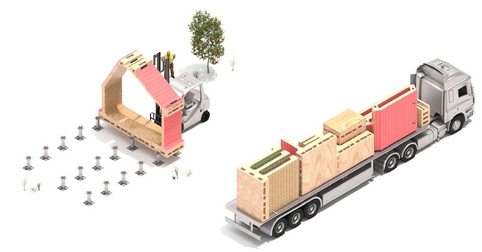
2-Stage Fabrication Process


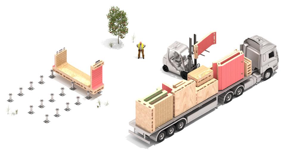
STAGE 1: Parts Assembly
STAGE 2:
(OFF-SITE) (ON-SITE)
- Assembled by Technicians
- All Parts Pre-Installed

- Loaded onto Flatbed Truck for Transport
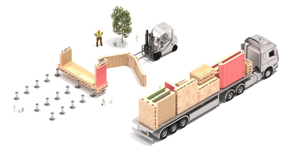
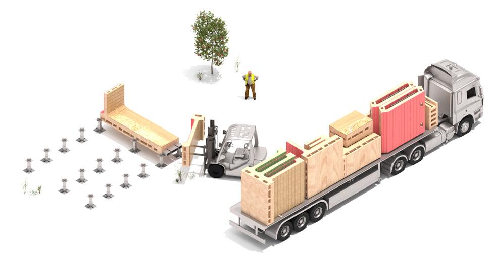
Module Assembly
- Primarily Assembled by People

- Components Plug-In to Construct Module


- Only Machinery is Small Forklift to Lift Components Off Truck


KIT OF PARTS:
Initial Classroom + Living Modules (13 Parts)
Optimized Classroom + Living Modules (6 Parts)
Plug-In: Ukraine / PrattGAUD / ARCH 770YP / Instructor: Juan Lago-Novas + Mor Segal / Team: Luis Rodriguez, Cristy Martinez, Jessie Ji, Jason Wong
STAGE 1: PARTS ASSEMBLY (OFF-SITE)


STAGE 2: MODULE ASSEMBLY (ON-SITE)



Assembled Modules
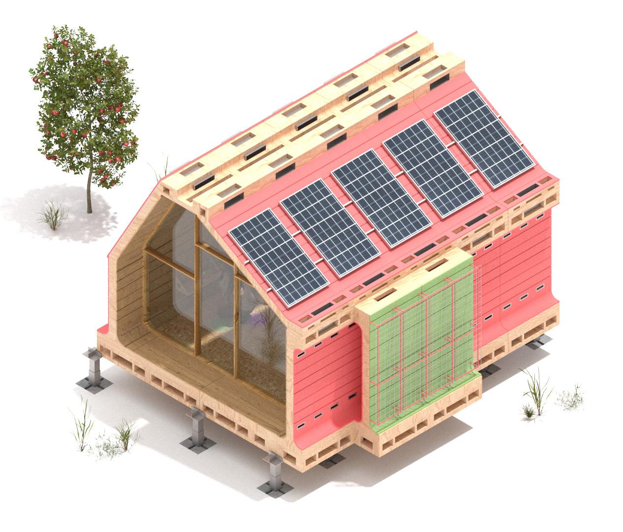

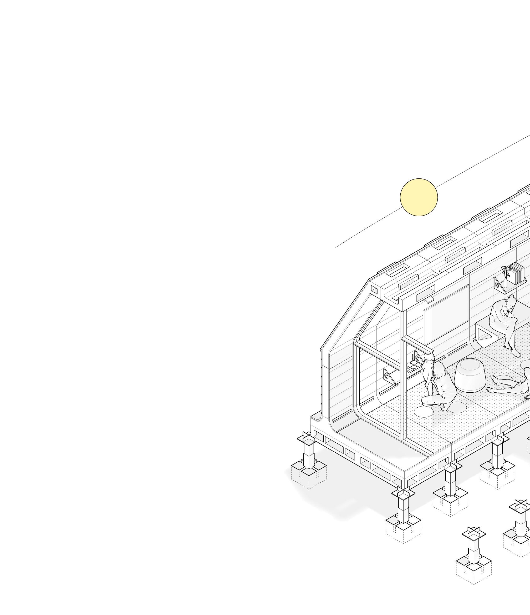
CLASSROOM MODULE: TECHNICAL DETAILS
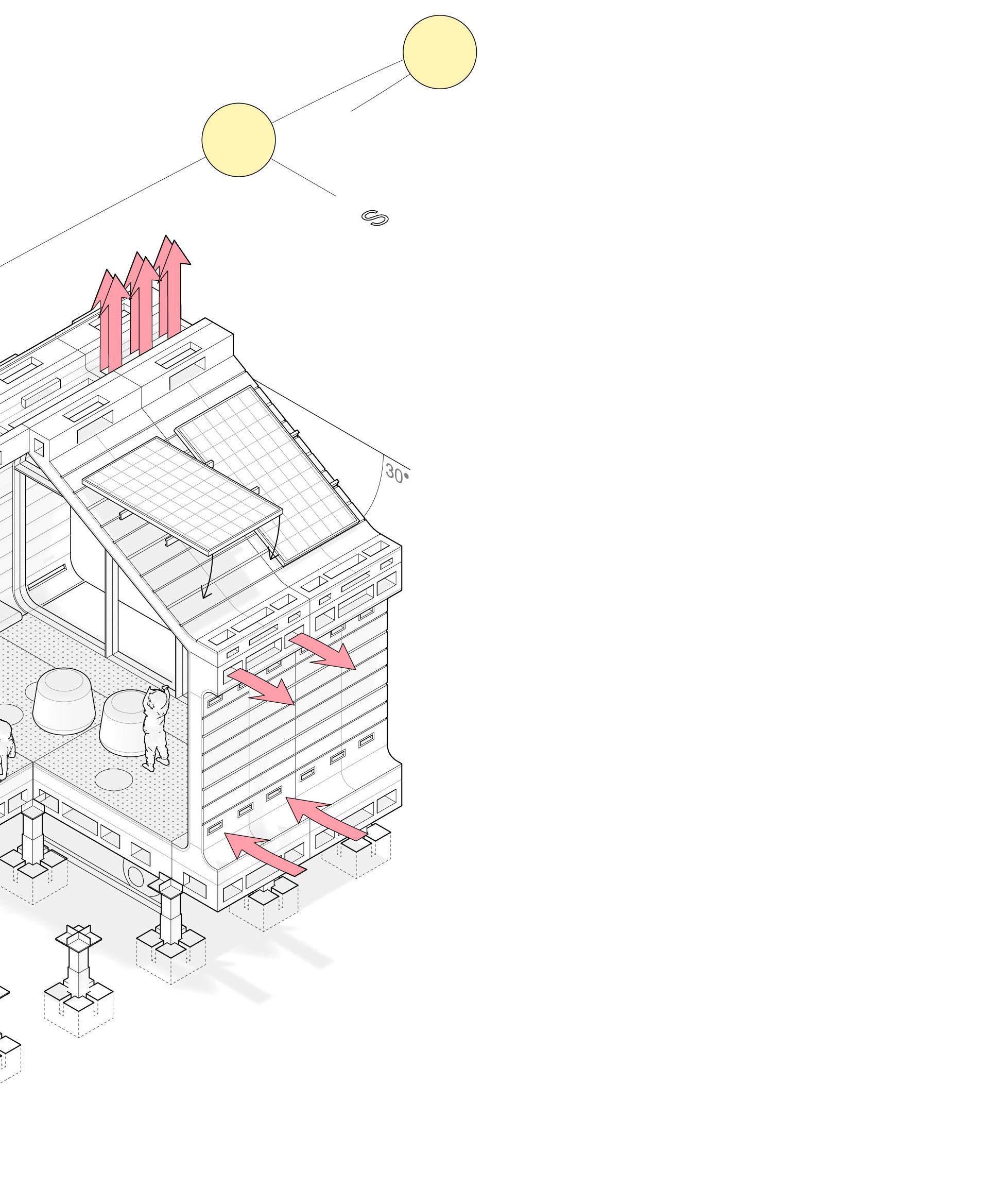
Solar panels oriented on southern facing facade
Vents open to circulate hot air out of the openings in roof above.
Vernacular Design

Components profiles inspired by Kyiv’s Historic District roof lines.

30 degree slope is optimized angle of incidence for solar absorption in Ukraine.
Furniture Flexibility
Furniture components like desk, chairs, benches clip-on.
Furniture Clips-On to FrenchCleat Panels
Vents close to circulate hot air away from interior
Double Paned Insulated Glass Panels
Cork Interior Floor Panels for Acoustical Insulation/Durability
Playful Gumdrops
Stools/Tables able to move and switch placement in module.
Classroom Module


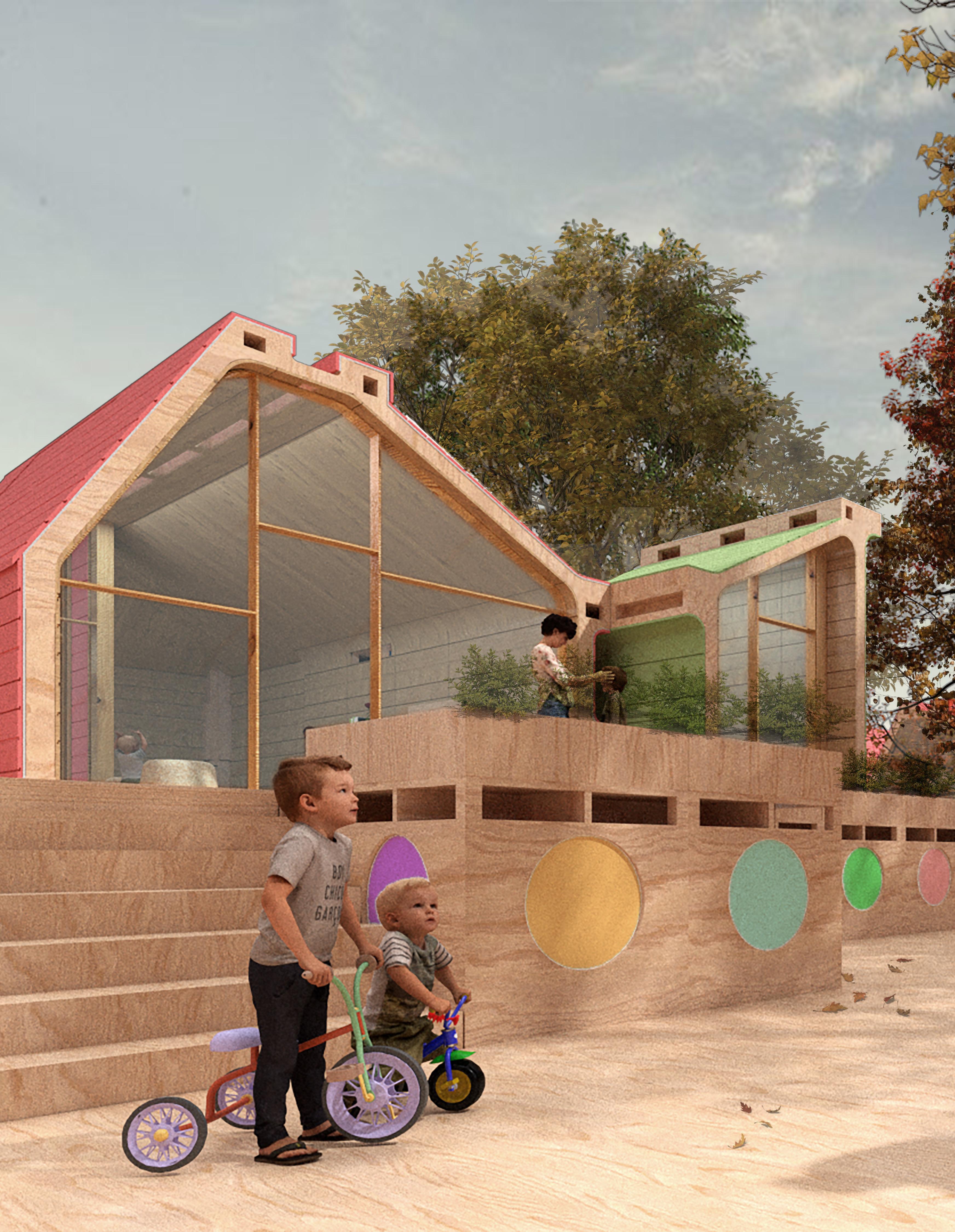
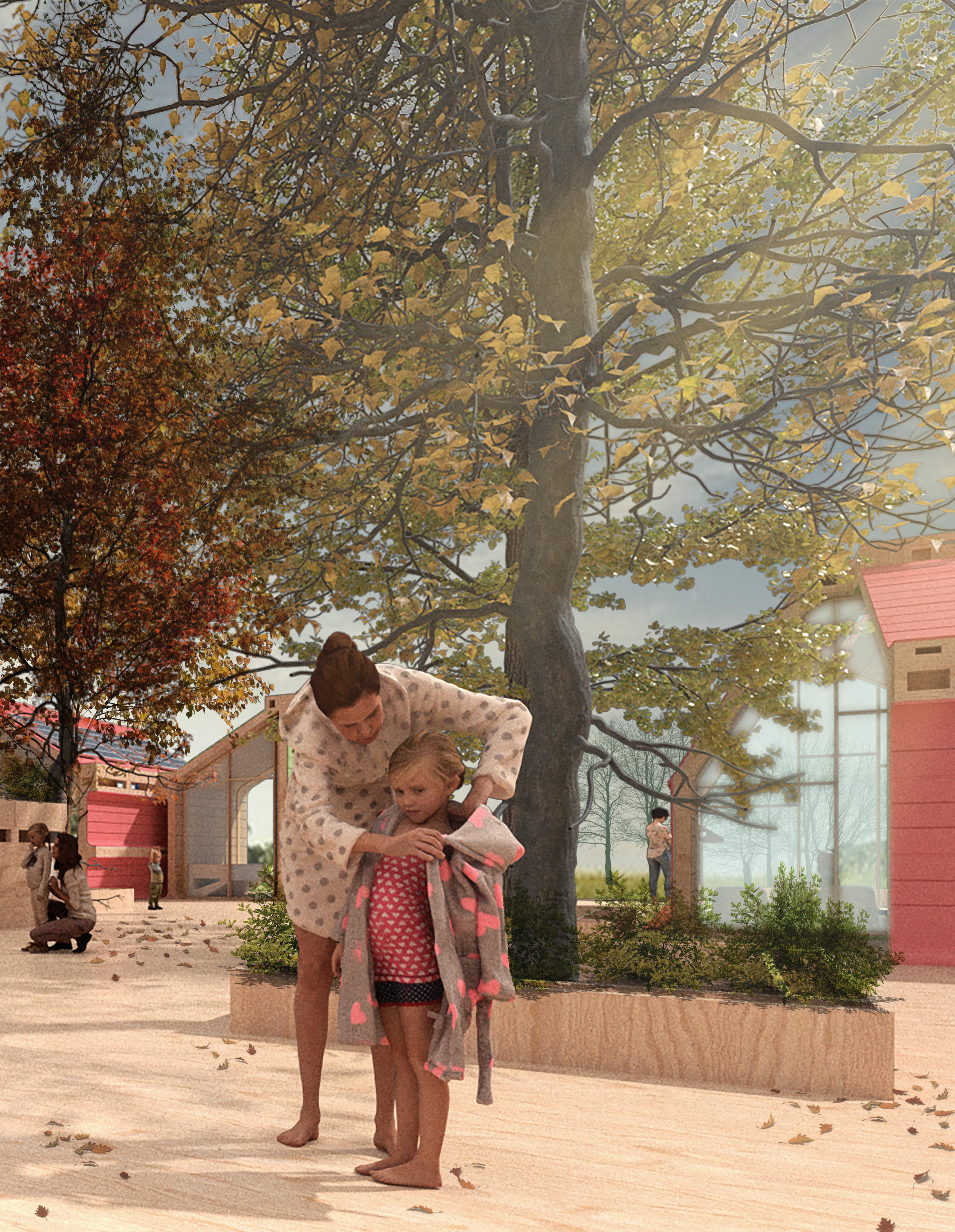
The design of the classroom module considered various criteria, unique to war children. Through material usage, light, and scale we aimed to aimed to create a safe, soothing learning environment.
Cistern for Rainwater Collection
Prefab Concrete Block Footing Below Grade
D1
D2
Solar Panel
Solar Panel Rail + Clip
Terracotta Cleated Panels
Metal Clips for Assem./Disassem. Aluminum Gutter Inlay Roof Sheathing
2 x 6 (1.5” x 5.5”) Rafter
Module Connection Slot
2” Diameter Insulated Pipe
Interior Wooden
French-Cleat Panels
1/8” Steel L-Angle
CNC Ribbed Profile
0.5” Diameter Threaded Rod 0.5” Hex Nut
5” Rigid Foam Wall Insulation R20 ZIP Wall Sheathing + Insulation R6
Terracotta Cleated Panels
Metal Clips for Assem./Disassem. ZIP Wall Sheathing + Insulation R6
5” Rigid Foam Insulation R20
2 x 6 (1.5” x 5.5”) Wall Stud
CNC Ribbed Profile
.5” Diameter Threaded Rod
.5” Hex Nut
2-Layers .75” Plywood
Module Connection Slot
1/8” Steel L-Angle
Welded Plate w/.75” Diameter Peg
Adjustable Steel Tube
3/8” Lag Bolt
11” x 11” x 7” Prefab Block Footing
1/2” Anchor Bolt
Gravel for Drainage
CLUSTER ANALYSIS: PARAMETERS


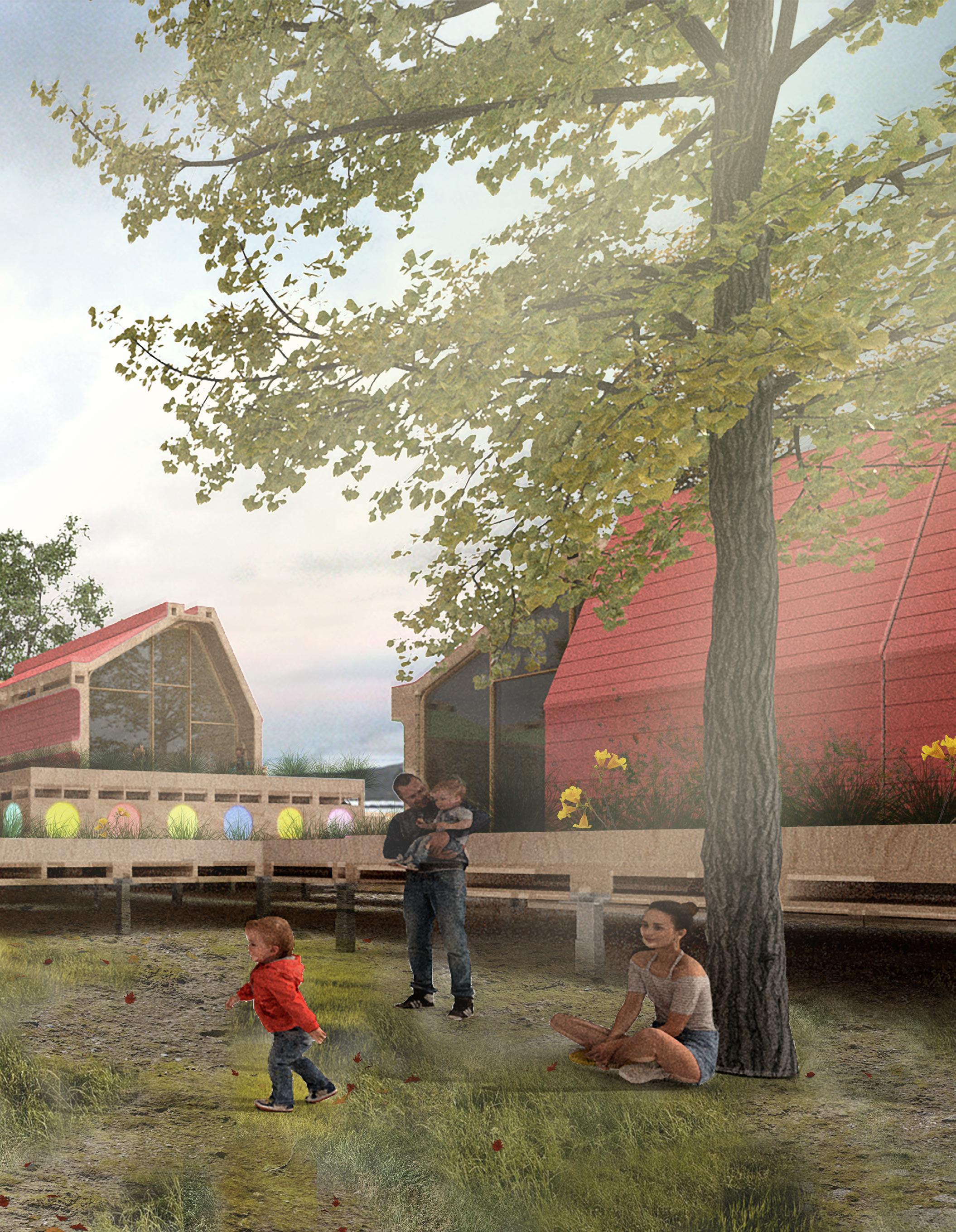
The temporary module cluster would be situated in the heart of Rzseszow, Poland, adjacent to the Wislok River. The site next to the river was chosen to give access to nature, as well as offer perhaps an emotional resonance to the Dnipro River back home in Kyiv.
GEOMETRIC INLAY
Exeter Library, Louis Kahn

BKLYN NAVY YARD: FRACTURE
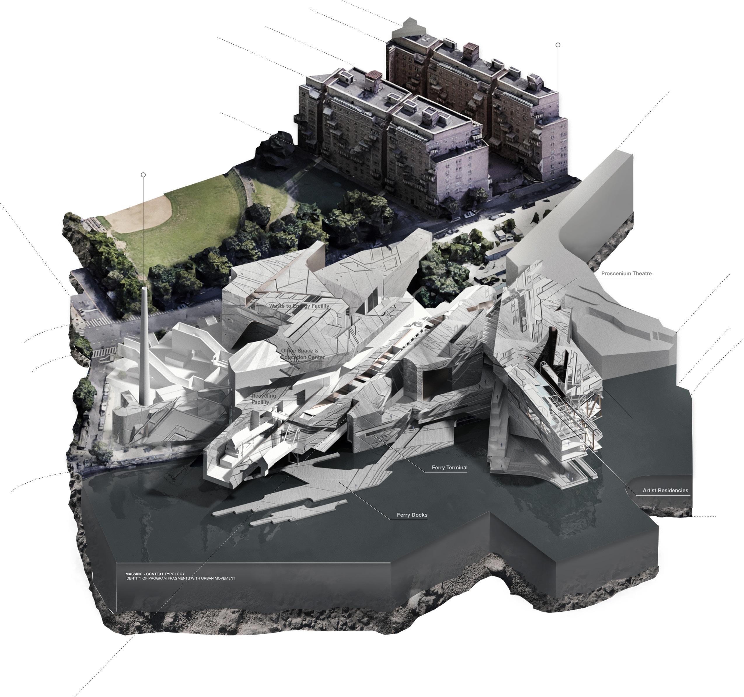
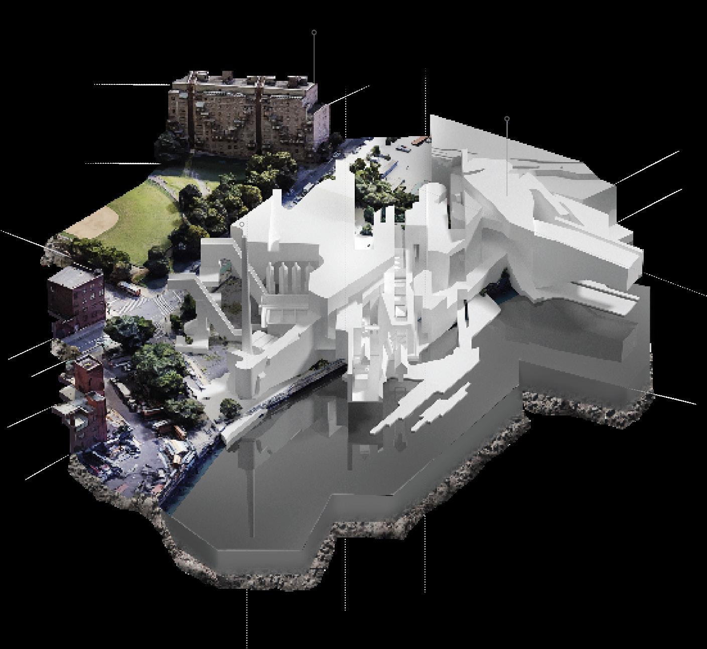
WTE + RECYCLING CENTER + A.I.R
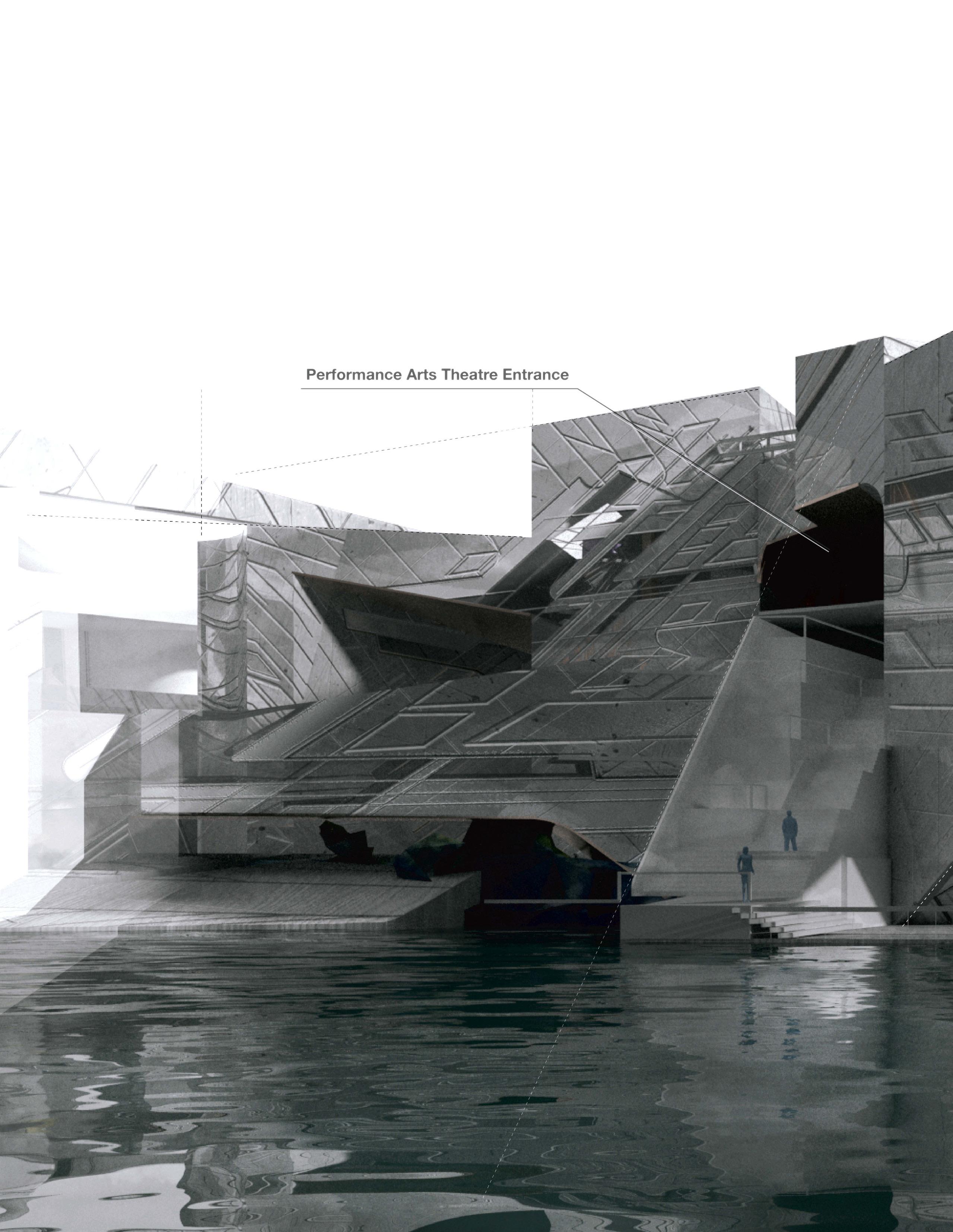
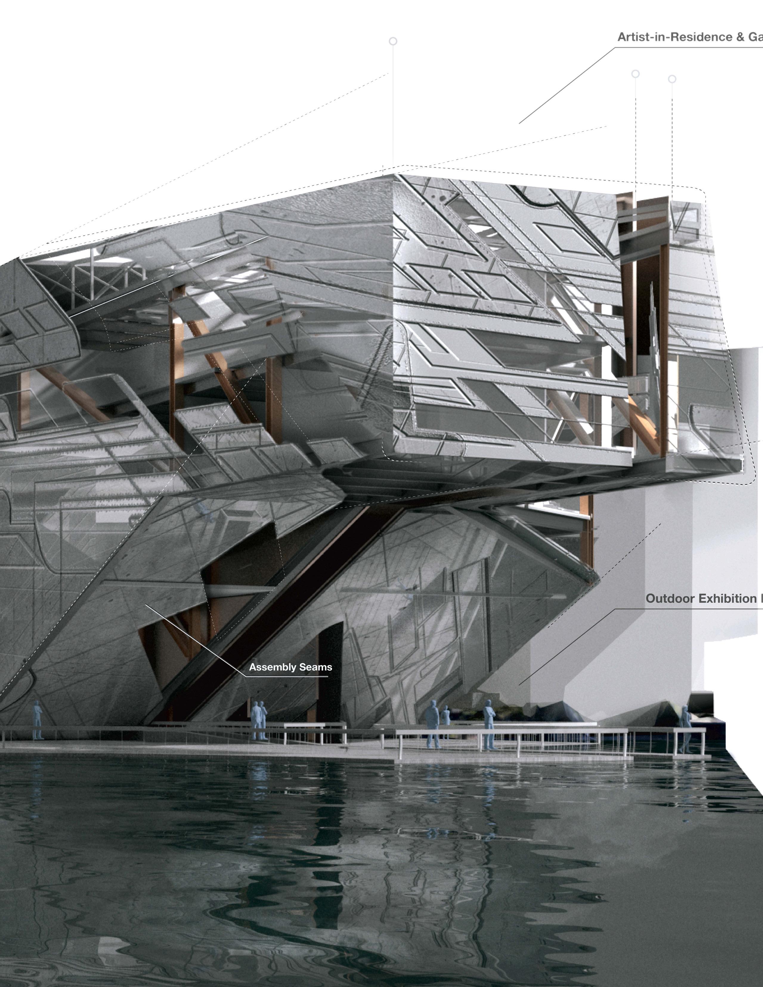
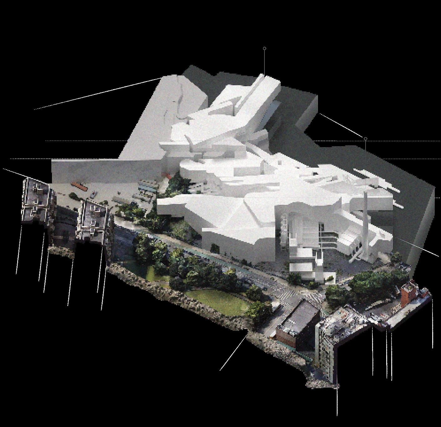
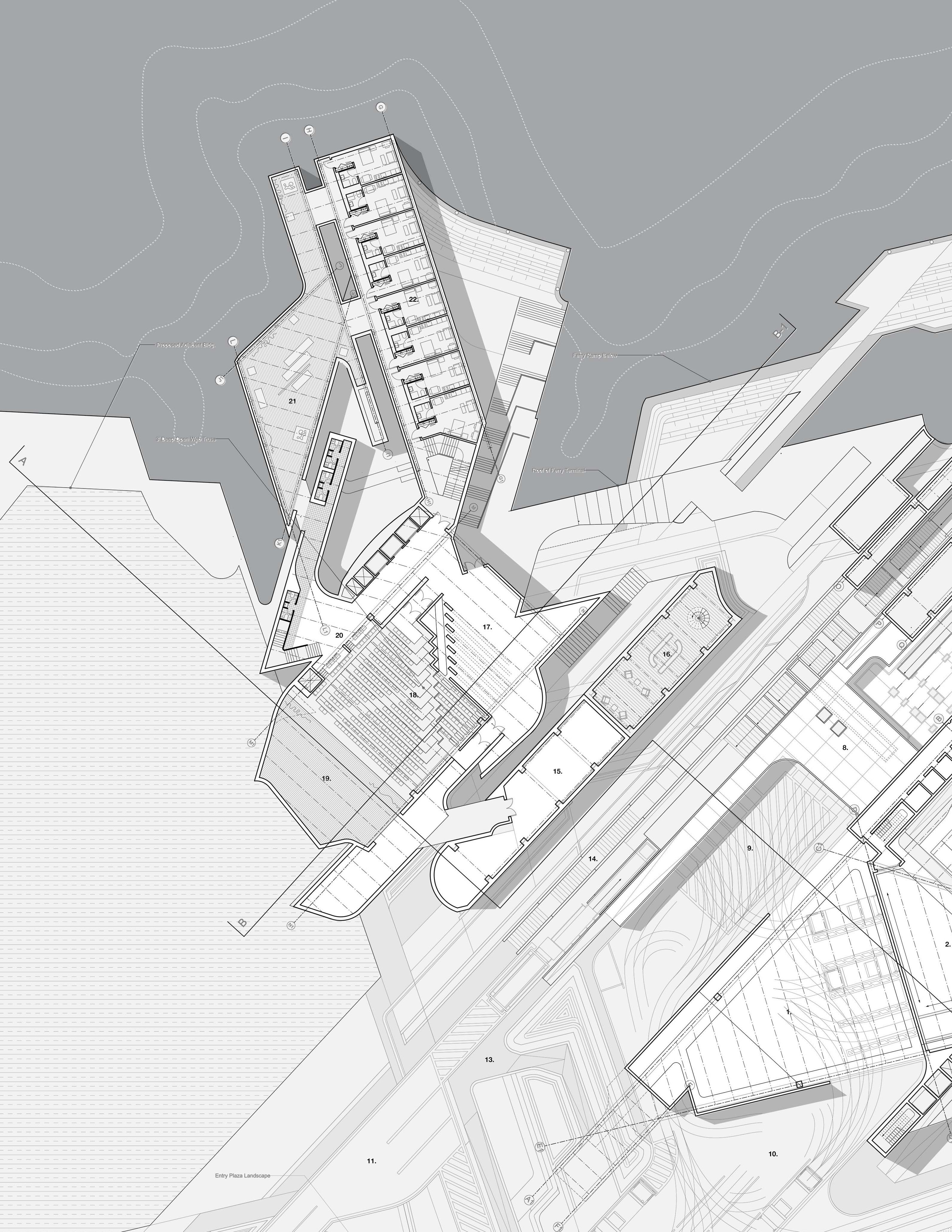
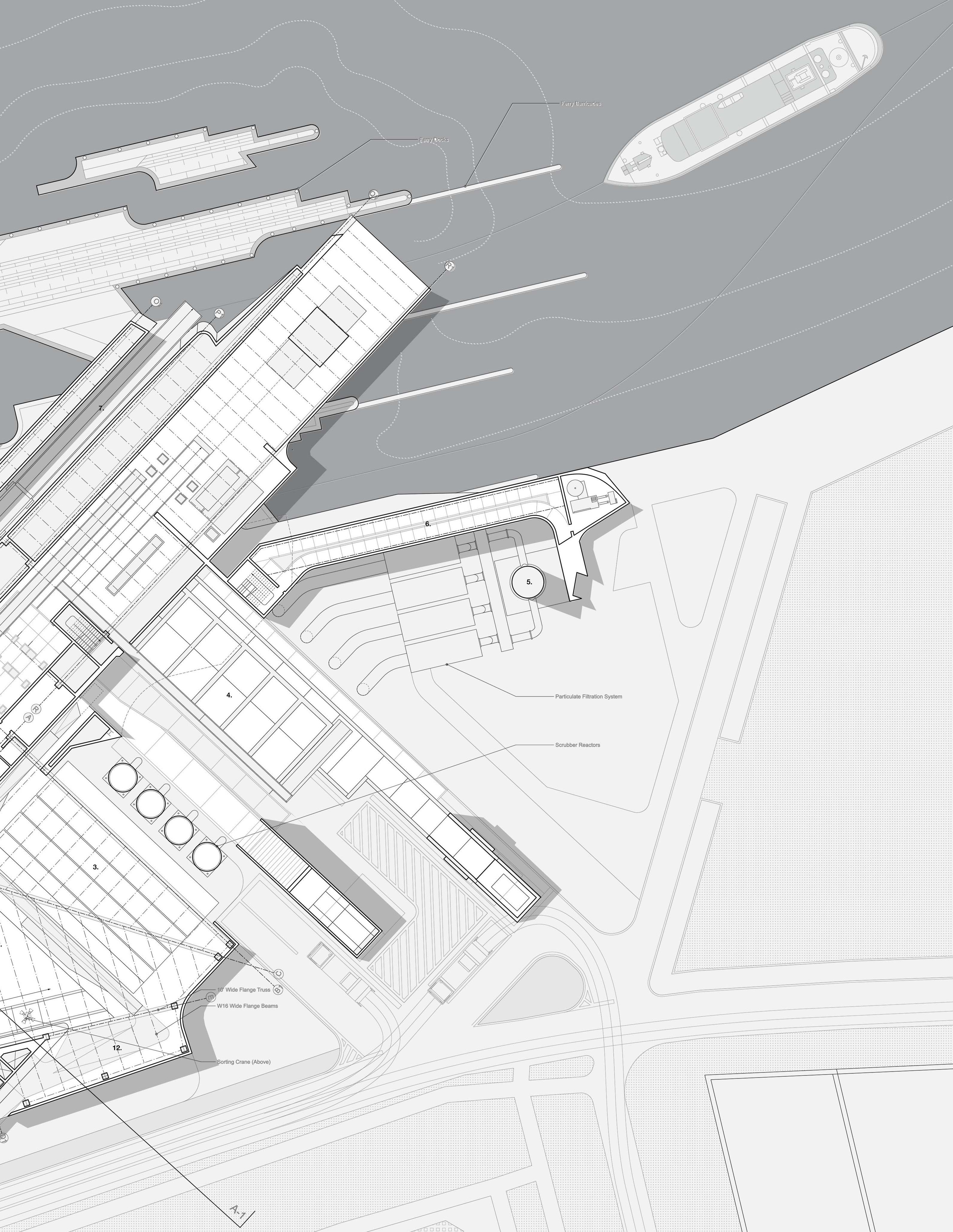
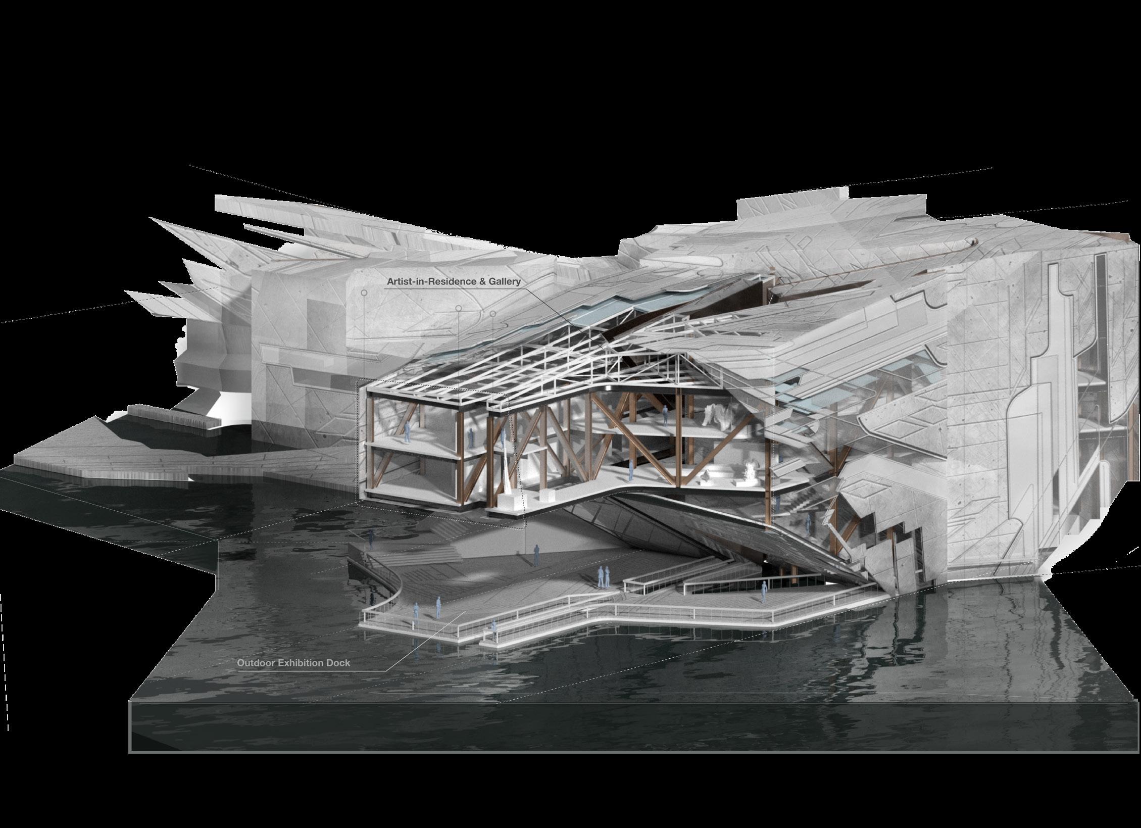
A number of varying programs comprise the project, including a Waste to Energy plant, Recycling Center, and Artist in Residence component.
The typology for the project was derived from the Navy Yard bulkheads and piers themselves. A set of design tool linework was developed
to act as the generator for the project’s overall formal expression. The massing is composed of many fractures along differing axes. The fractures were used as a means to help direct the occupant in a certain direction, in particular a primary fracture is on axis with Kent Avenue, and projects out toward the channel, as a means to connect the streetscape, to the waterfront.
The idea of “fracture” as a generative driver for the project was expressed at varying scales. It is used as the primary action upon which the formal massing is configured, used again as
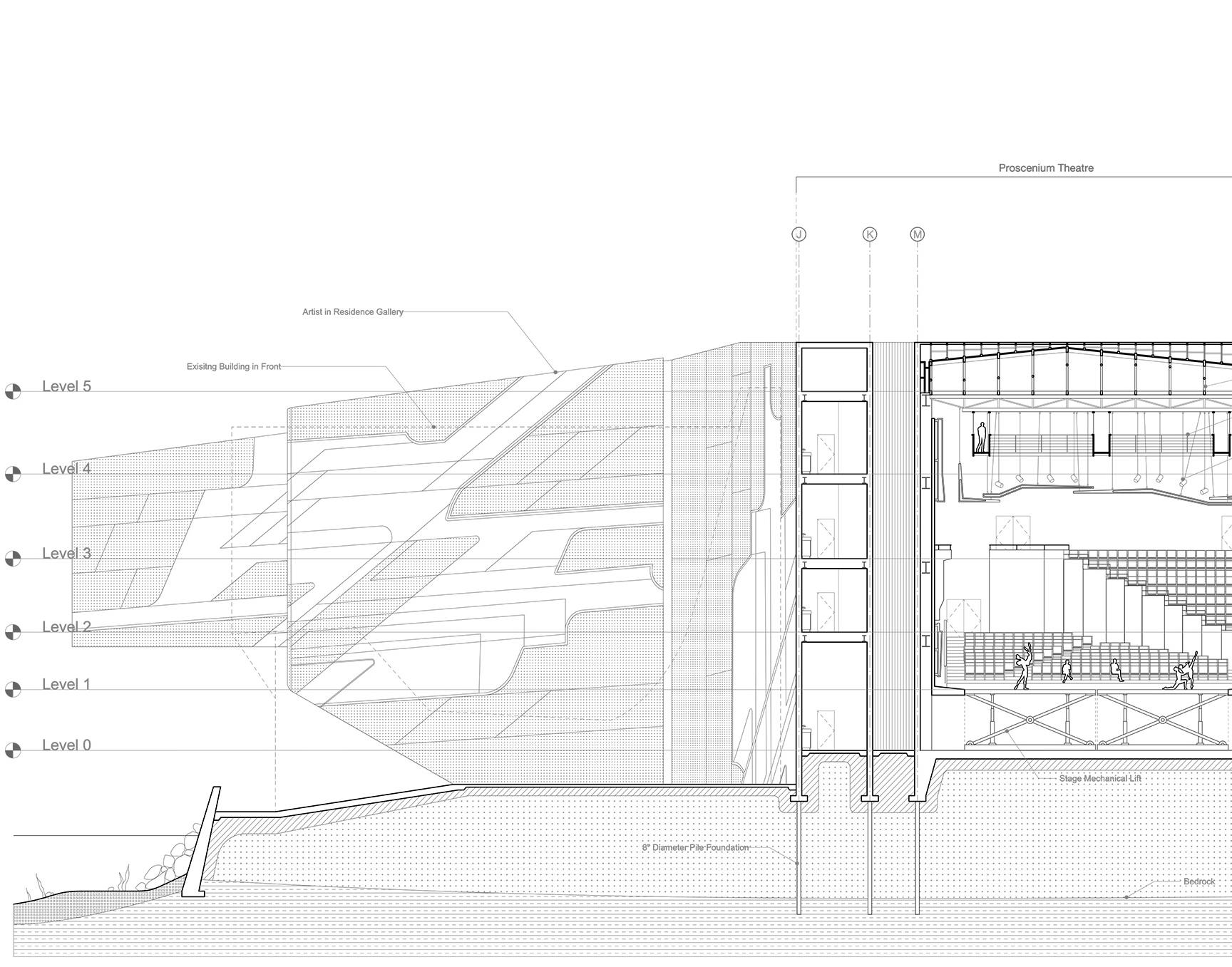
a means of circulation within the project, and is also used at the scale of the theater as the lower and upper seating areas are created through a penetration and ensuing fracture.
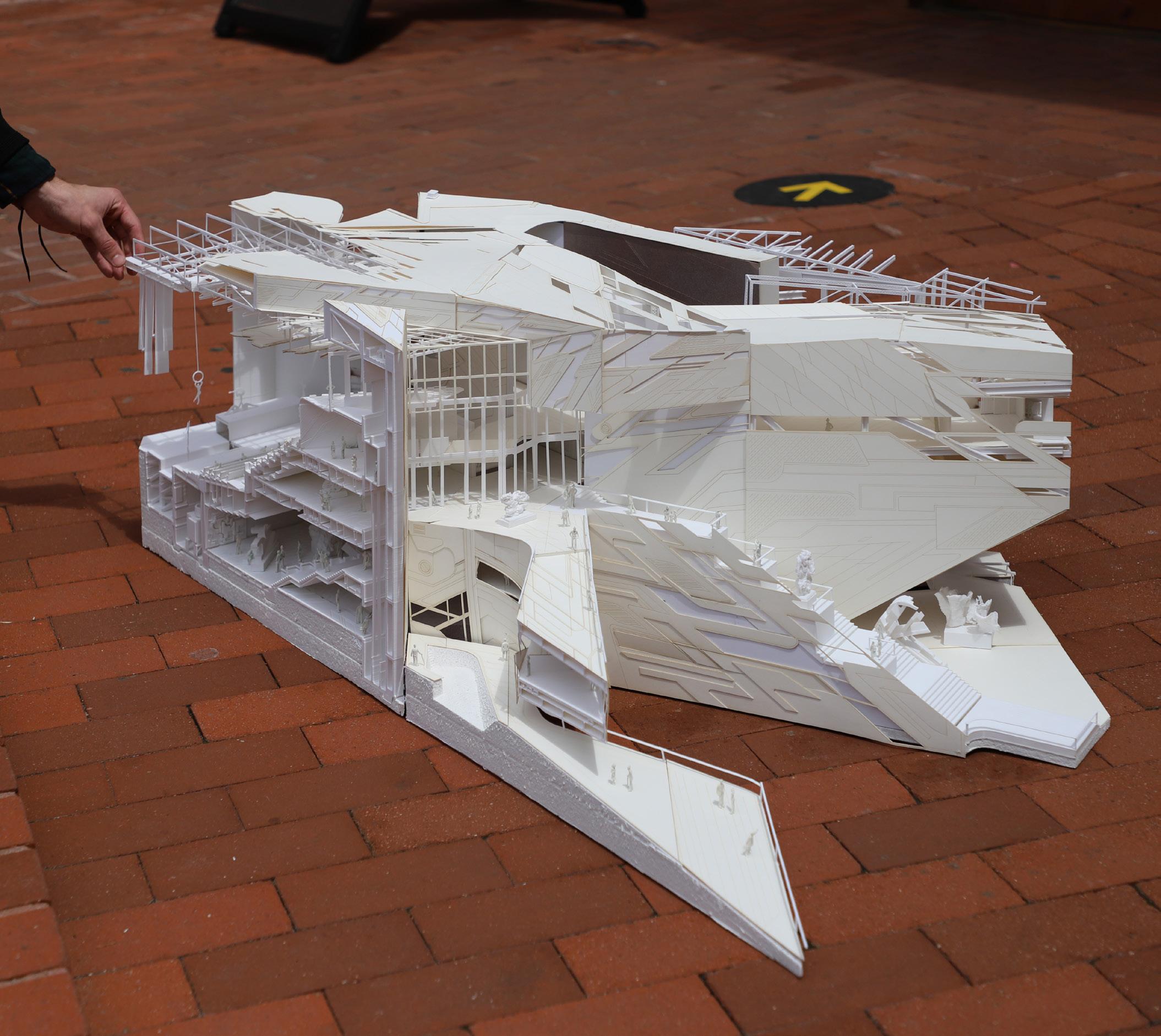
A large 3/16” scale chunk model of the A.I.R program was constructed which included a section through the proscenium theater, art gallery, and artist’s residences, as well as the structure and MEP systems.
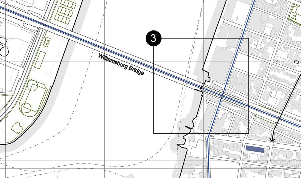
NYC 2020 VISION GOALS
Along the East River Corridor
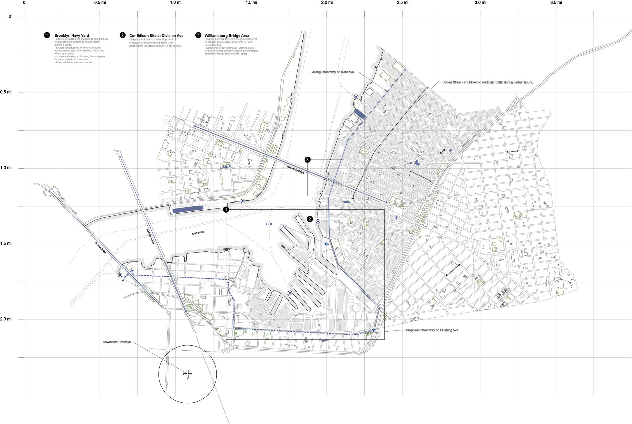
- Continue replacement of bulkhead and piers, as well as complete drudging to ensure future maritime usage.
- Explore opportunities for controlled public access around and within Brooklyn Navy Yard where appropriate.
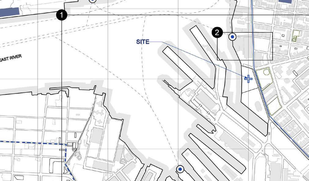
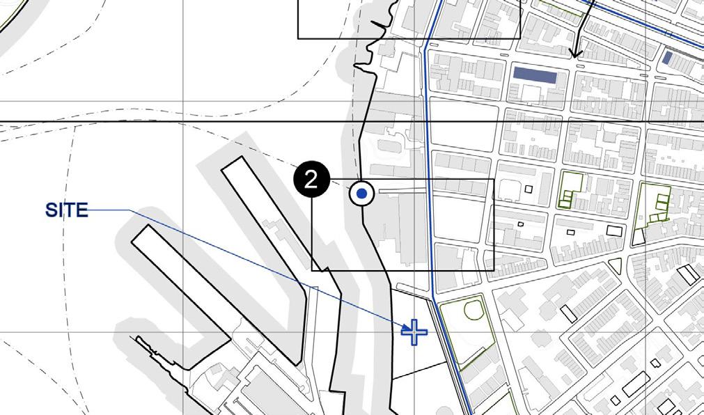
- Explore options for redevelopment of industrial and commercial uses with opportunity for public access if appropriate.
- Explore potential for under bridge development on relocation of current DOT and DCAS facilities
- Commence redevelopment of Domino Sugar Factory
Massing Studies
a.. Massing + Skin
b. Massing + Fracture
c. Massing + CityScape
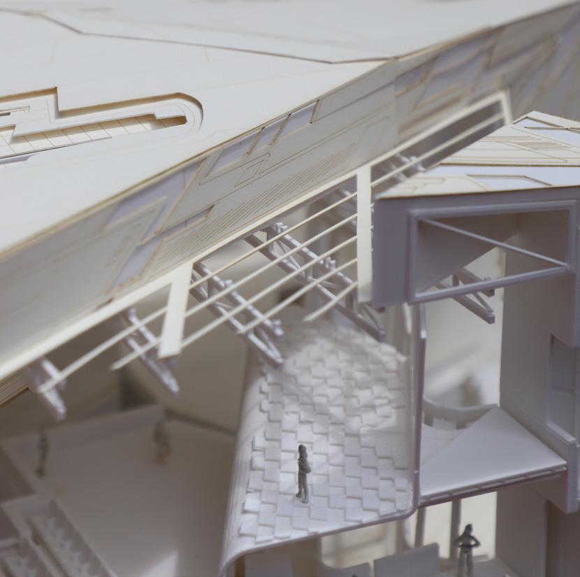 a. Performance Theater - Upper Viewing Platform
Model Photo
b. Longitudinal Section - Cutting Through Theater, Recycling Center, and Waste To Energy Programs, as well as Kent Avenue.
c. Cross Section - Cutting Through Performance Theater, Art Gallery, Elevator Shaft, Ferry Terminal Bridge, as well as Structural + MECH. Systems
Sections
a.
b.


Model Photos
Model Specifications
Dimensions - 52.5” x 24” x 18”
Scale - 3/16” = 1’0”
Materials - High-Density Foam, PLA Filament, Foam Core, Watercolor Paper
Fabrication - 3D Printing, CNC Milling, Lazer Cutting
 Shown at Wast[ed] Event Hosted by SOM
a.. Overview of Model - Higgins Hall Courtyard
b. Section Cut - Gallery + Theater + Elevator
a.
Floating Panel System
3” Self-Tapping Screw
Panel Substrate
Threaded Rod
Waterproof Membrane Gutter
Corrugated Steel Decking
4” x 8” Steel C-Channel 6” Steel Stud
6” Rigid Foam Insulation
3/4” Gypsum Wallboard
3/4” Gypsum Board
Aluminum Panel
Steel Girder 1/4” Steel Angle
Panel Substrate
Mullion Clip
Double Pane Glazing
Welded Girder Plate
Tension Cable
Enclosure Details
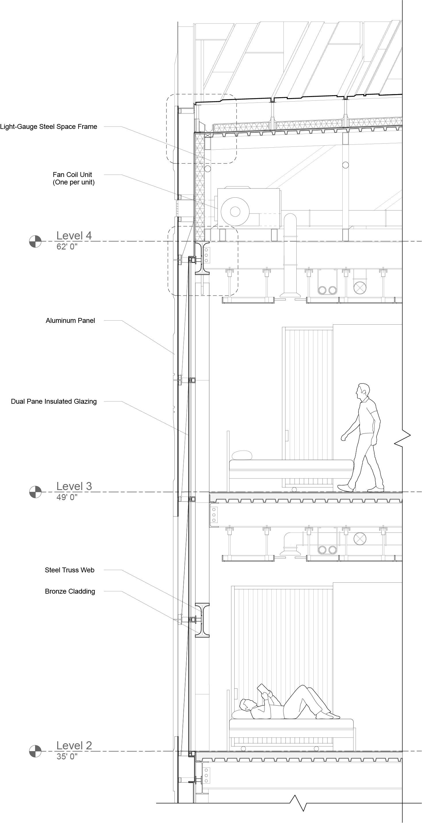
a. Wall Section - A.I.R Residence’s, steel frame construction, channel rail substrate, and aluminum panel cladding offset from interior glazing
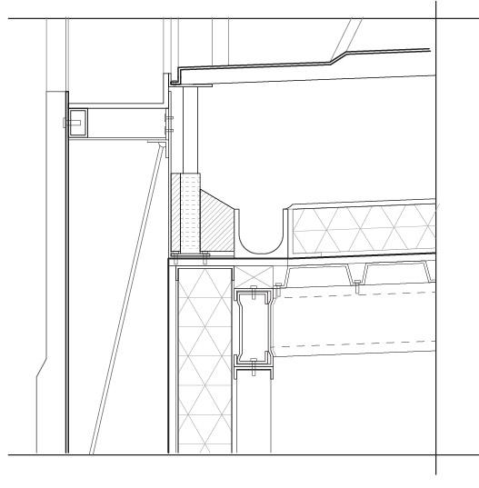
b. Detail 1 - Floating paneling, waterproofing, and drainage system at joint between wall and roof
c. Detail 2 - Slab and wall joint including connection between steel frame primary structure and substrate

Tranquil Respite
Rest Stop - Archer, Florida

NSF COMPETITION
Urban Shorelines: RE-Designing the Seawall
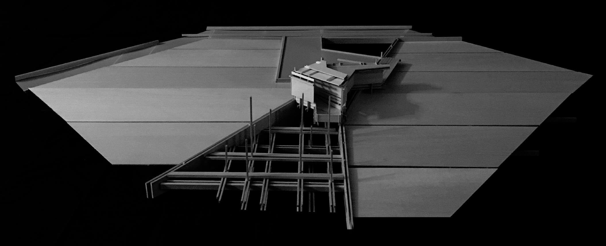
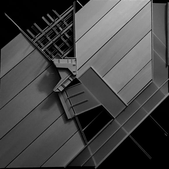
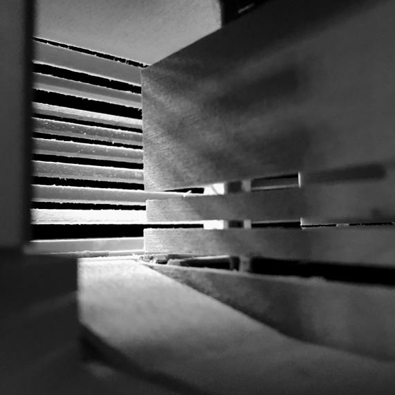
The National Science Foundation (NSF) had awarded a grant to teams to further the research on sustainable innovations in relation to our built environment. Contracted via Philip Parker Architects, our project, Urban Shorelines, centered on how to re-design the typical seawall, and re-imagine it as a living shoreline.
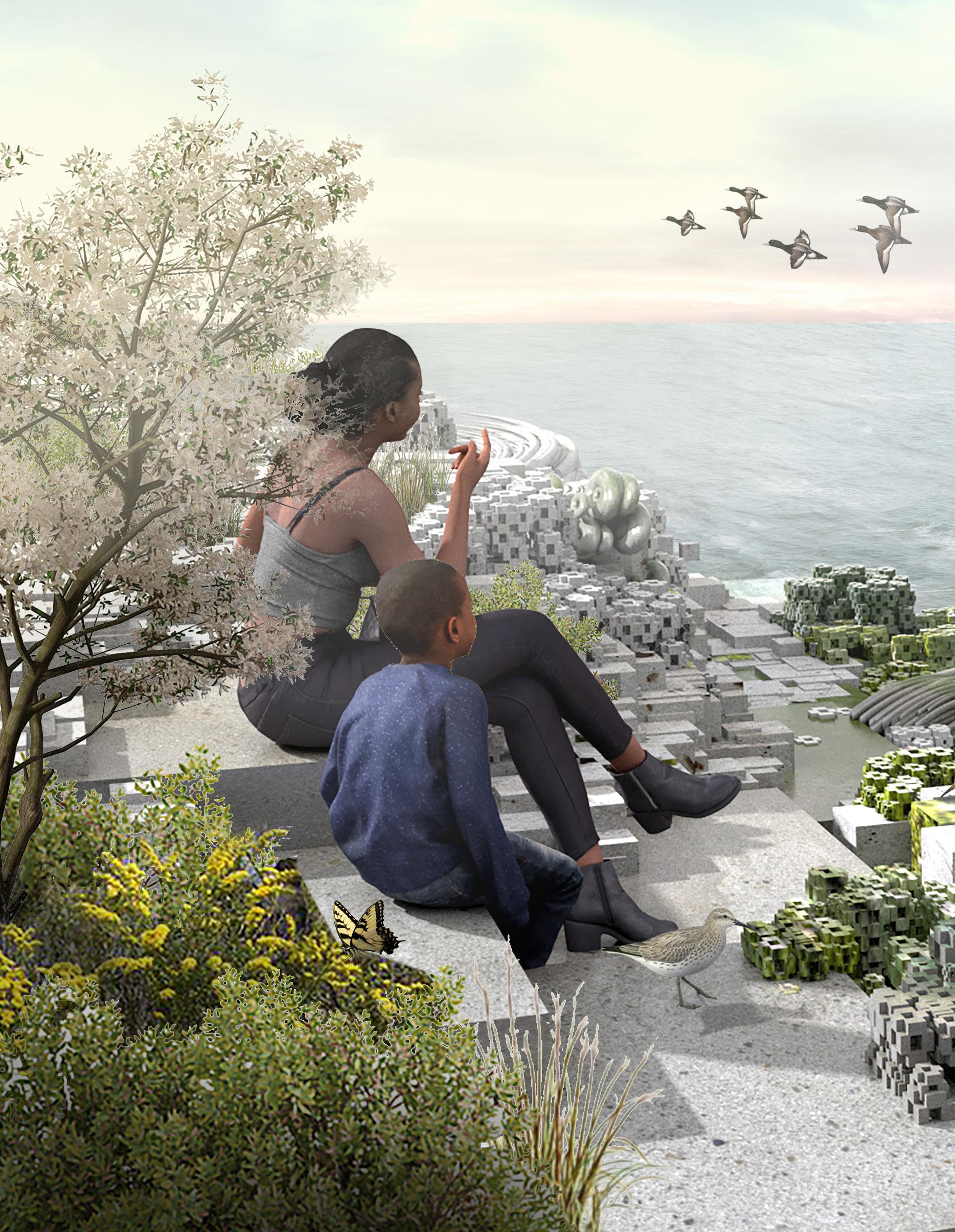
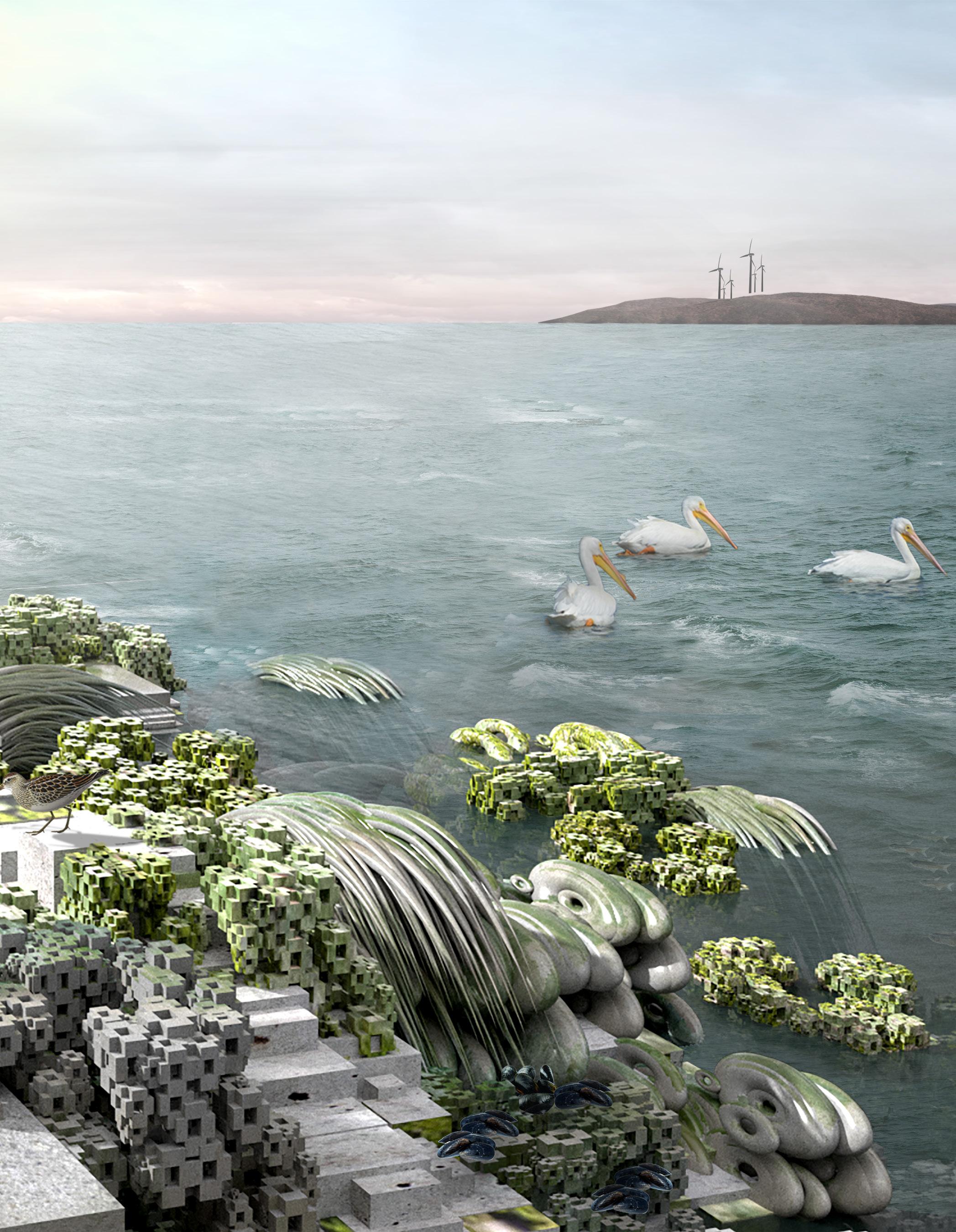
Instead of viewing the seawall as the partition which draws a distinct line between what is built and what is natural, Urban Shorelines looked to challenge this notion, by blurring the zones between city and water. In addition, these strategies could be used to expand the city’s
infrastructural connections to its ocean setting, and to increase urban resilience.
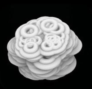
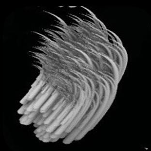
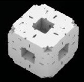
The new design of the seawall included components varying in form from curvilinear grass-like strands, to disks, to sponge-like blocks, all designed to house various marine life. How these components are arranged on the wall in relation to the zone of marine habitat, creates a rich textural mosaic, instead of an abrupt hard seawall.
The living seawall could be modularized as well, to accommodate various profiles, ranging from vertical, to projected, to gradually sloped,
facilitating different interactions with the water’s edge.
It was a great experience to work in a crossdisciplinary project from the start. Having the opportunity to work with ecologists, engineers, as well as other designers and architects, added to the overall strength of the design from its conception.
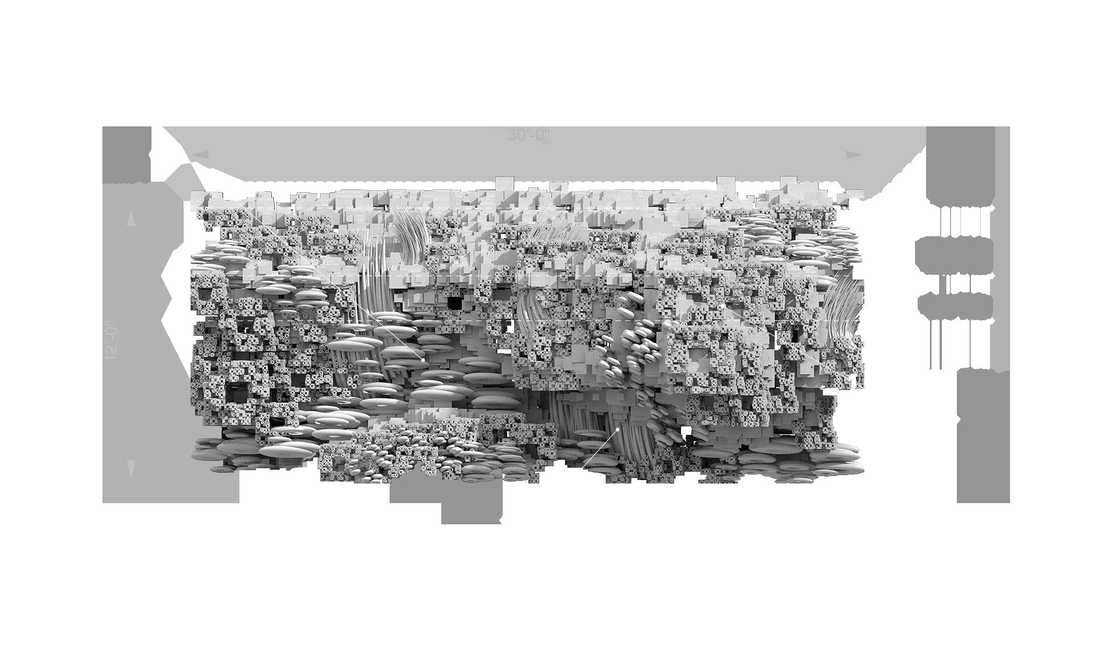
Seawall Mosaic
a. Mosaic Panel Elevation - 30’ x 12’
b. Component 1 - Small Cube
c. Component 2 - Grass-like Brush
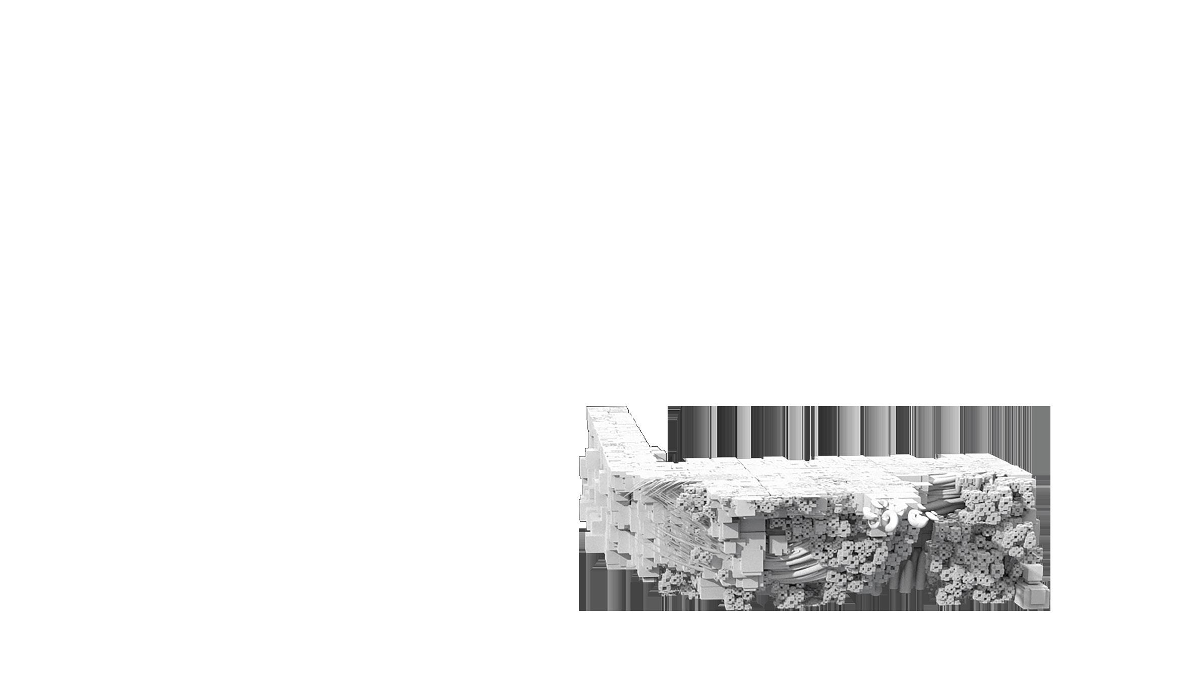
d. Component 3 - Disk
Fabrication
a. Amphitheater - Facilitate community engagement
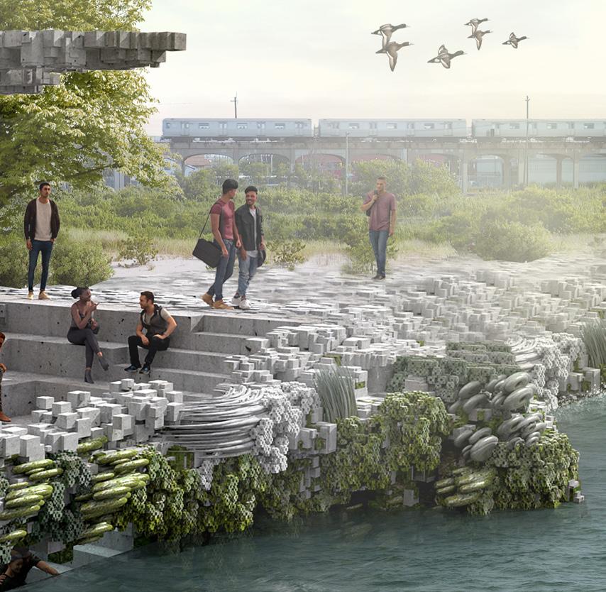
Render b. Vertical Section - Shoreline section can be modularized for vertical section

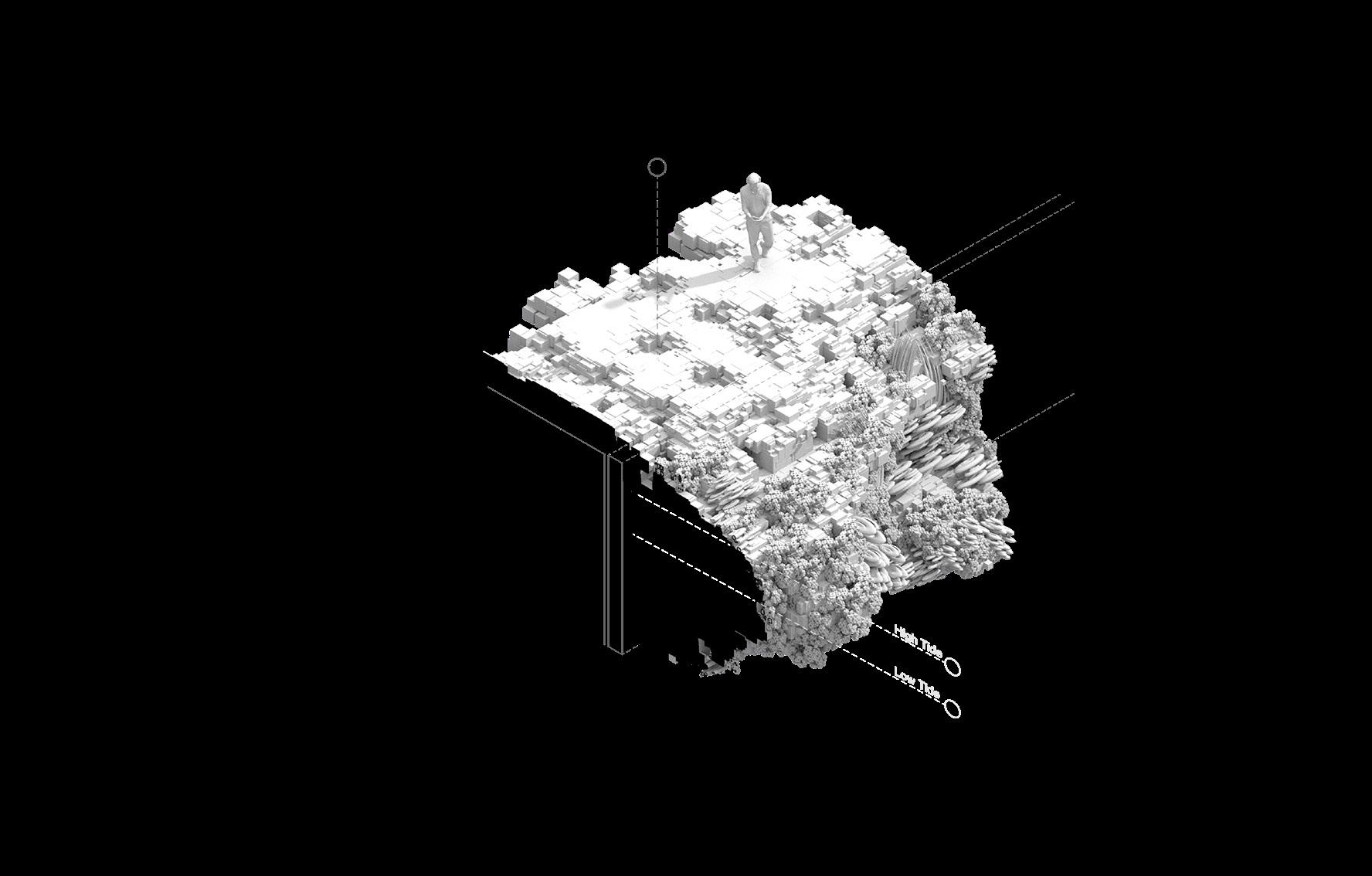
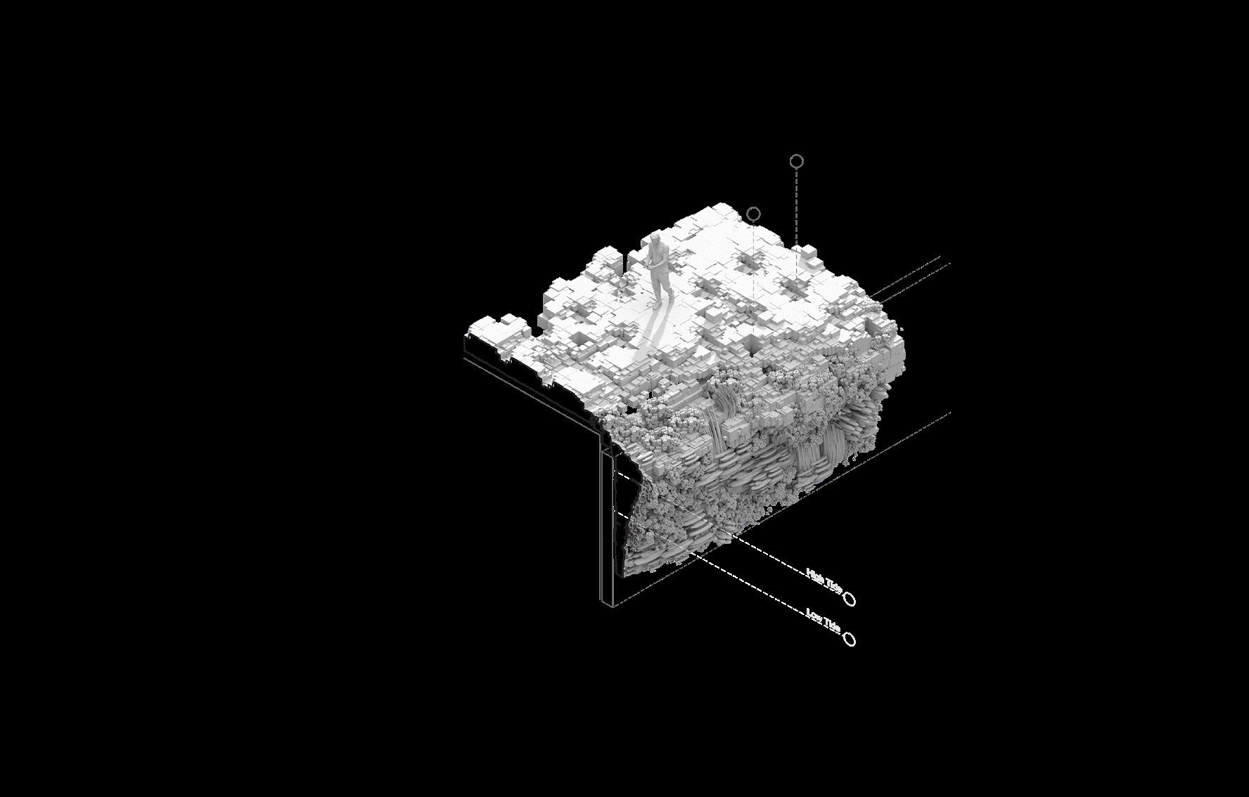
c. Projected Section - Shoreline section can be modularized to project into the water.
d. Sloped Section - Shoreline section can be modularized to slope towards water and offer opportunities to interact with high/low tide.


SCALE + ORIENTATION + PERCEPTION Design Research Studio
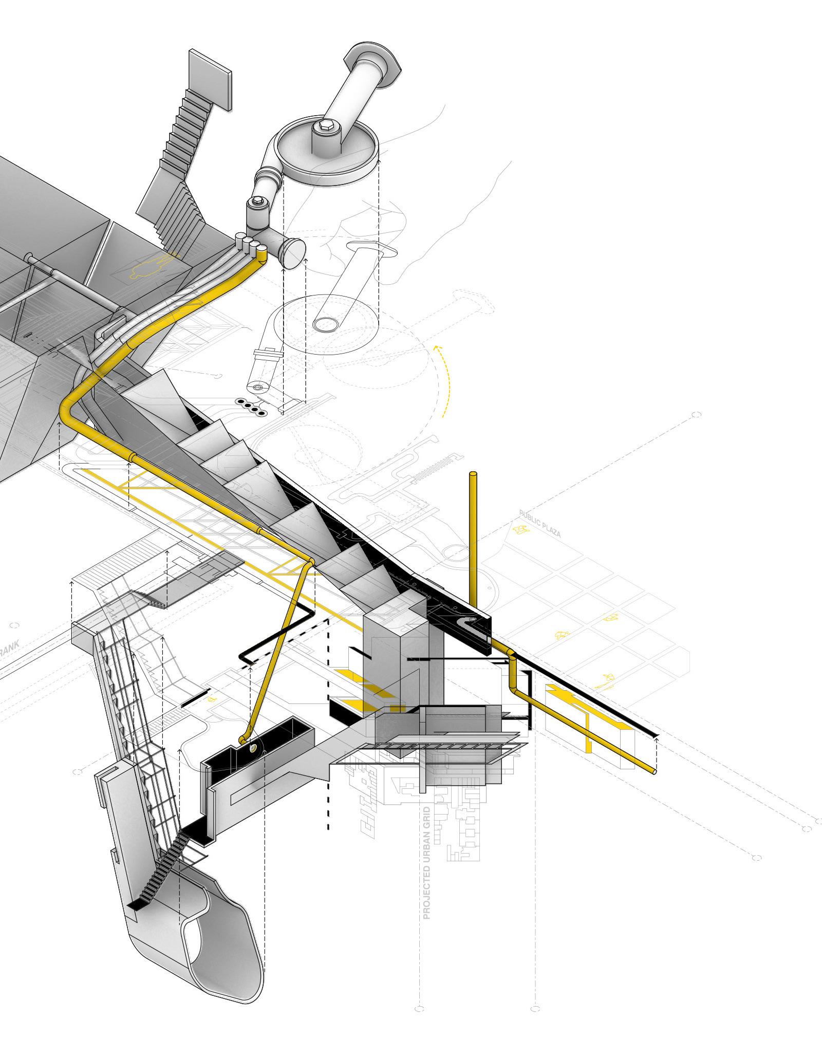
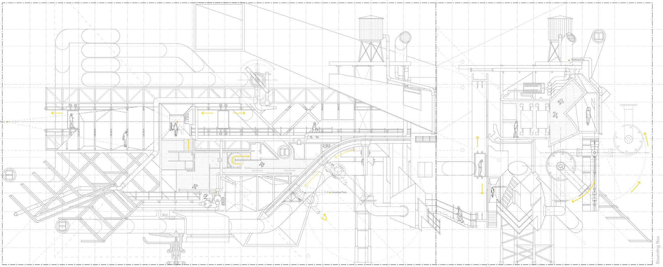
The research for this project initially began by asking the question, “How can one challenge the 2-dimensional to 3-dimensonal architectural process?”. Historically, the architectural process has consisted of a 2D to 3D workflow. A set of 2 dimensional, planar, drawings are used to visualize a 3 dimensional space. But does a 2D drawing really exist?
To start, 5 architectural drawing conventions were selected: Plan, Section, Elevation, Axonometric, and Perspective. As well as, three scales were identified: Instrument (something operable by hand), Building (a construct which
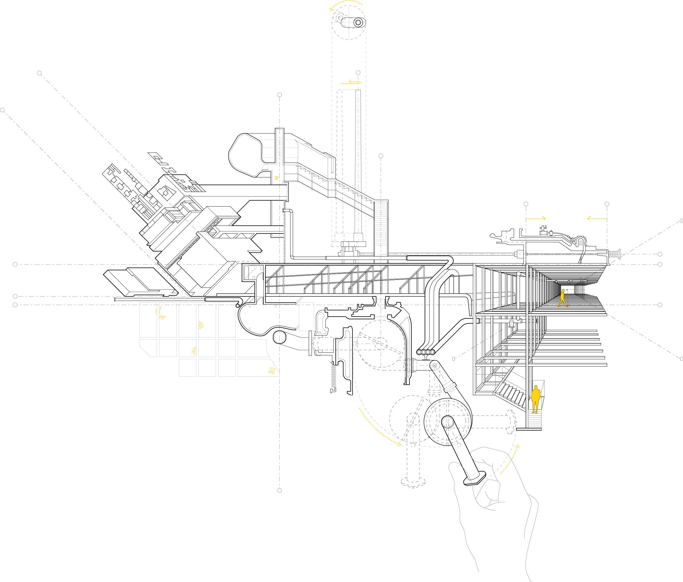
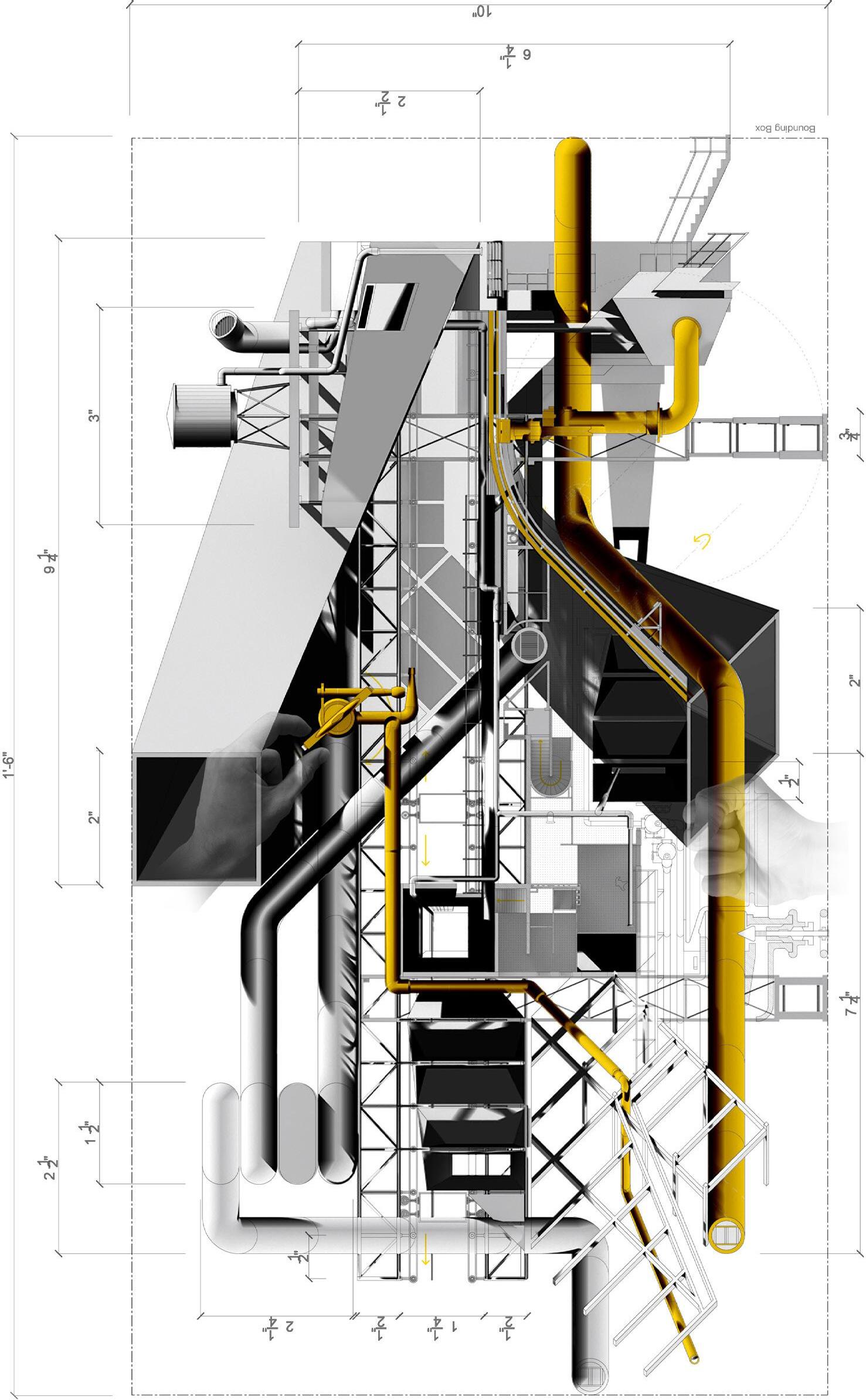
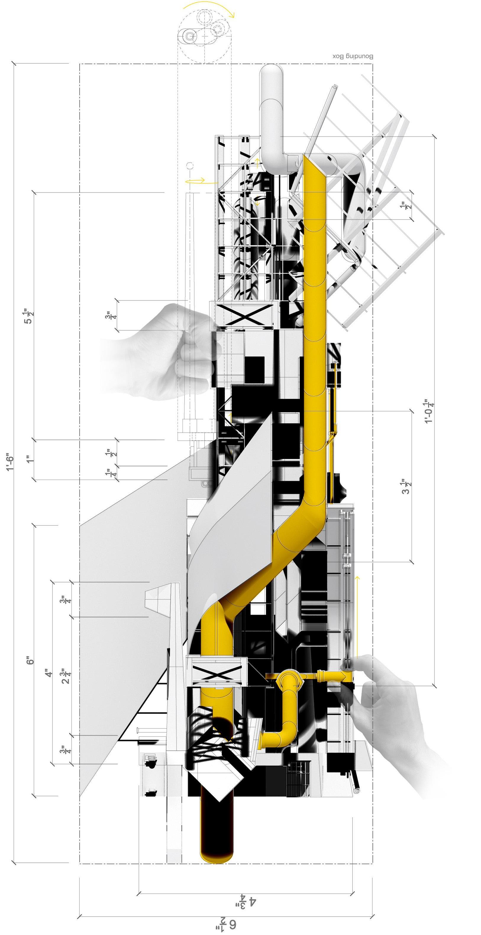
could be occupied), and Urban (a larger matrix or network in which we operate within). Through compiling differing architectural conventions, in addition to considering multiple scales, Collage was used as a medium to find moments of resonance between each of the various attributes listed.
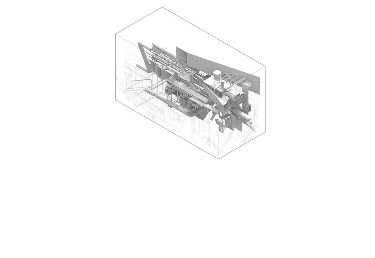
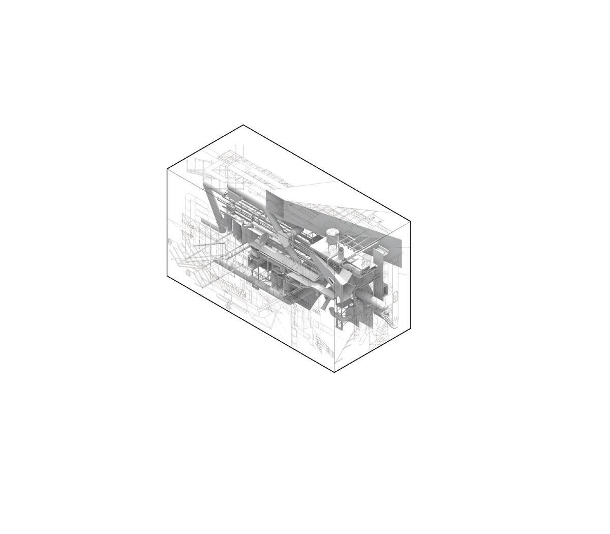
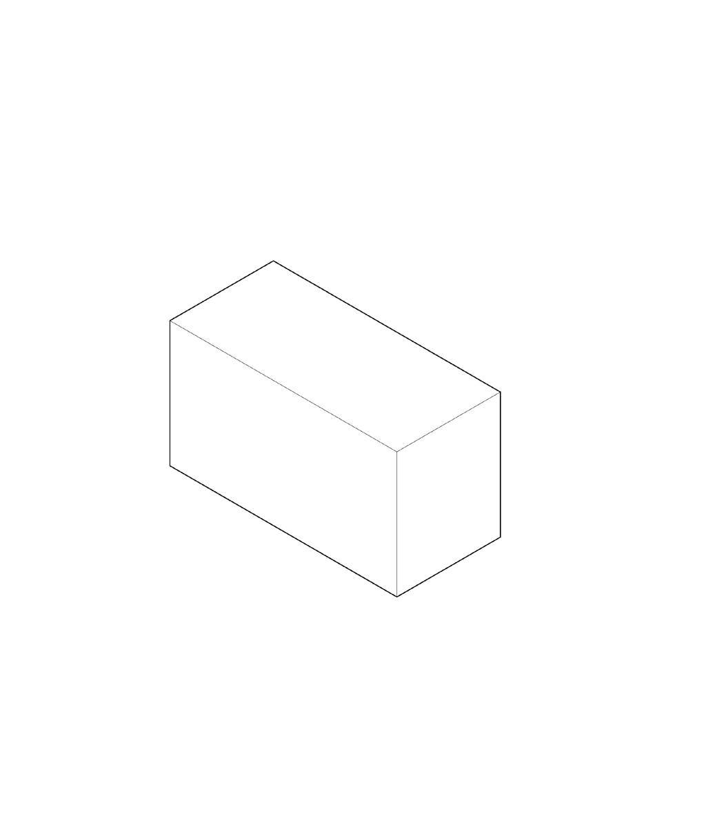
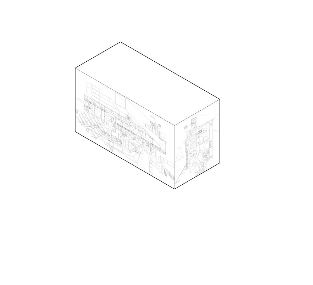
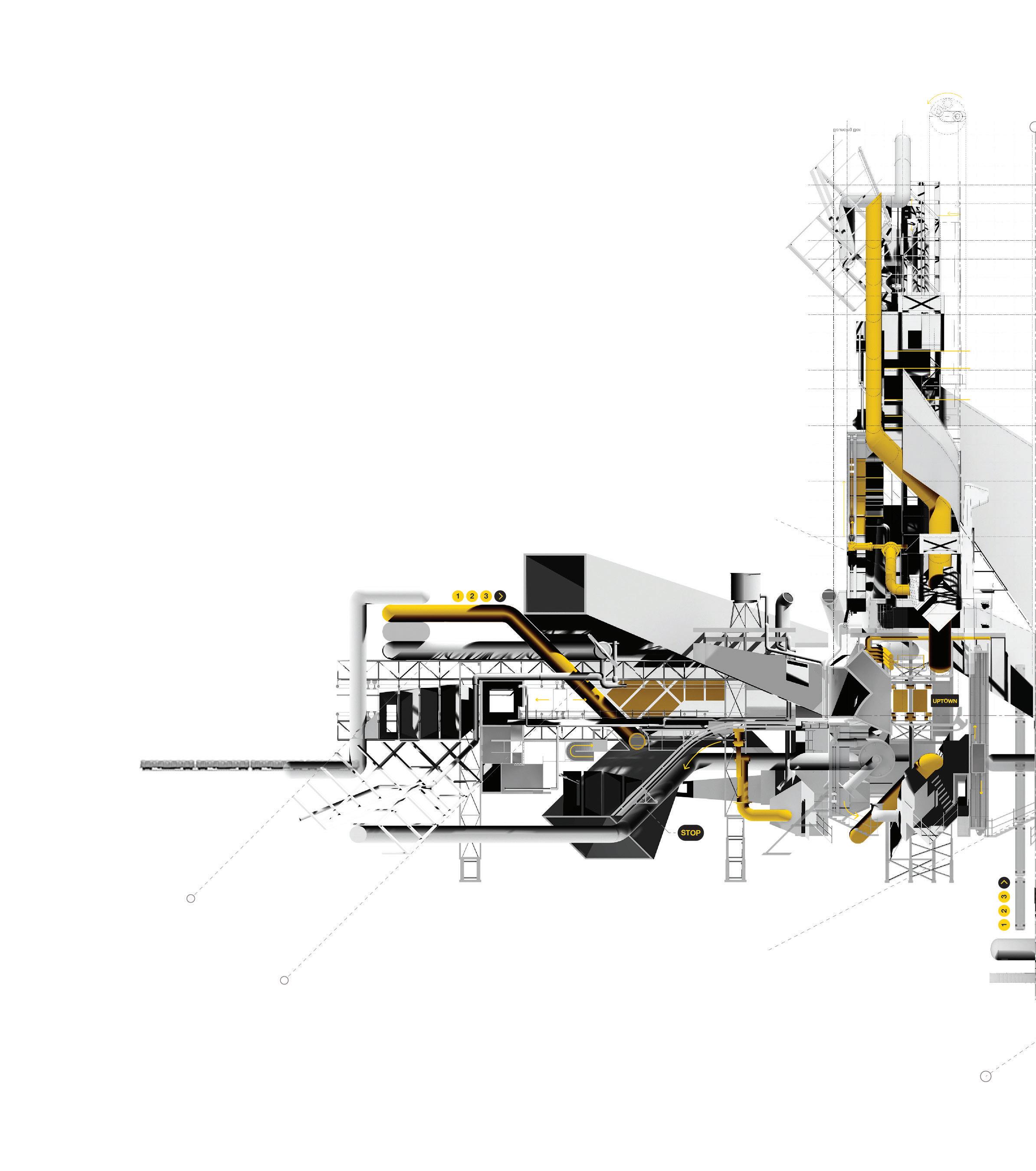
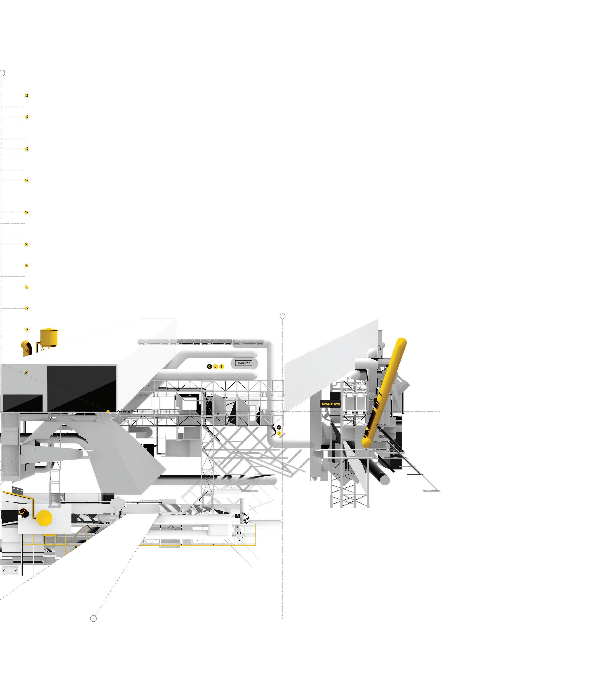
Collage was then used as a generative technique to further investigate how one could combine various scales and drawing conventions into a singular composition. Once a pair of 2D drawing compilations were generated, the Bounding Box (an inherently 3D
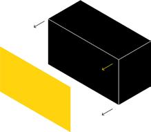
object) was used as a tool to both assimilate varying scales through using a singular face or partially or completely unfolding.
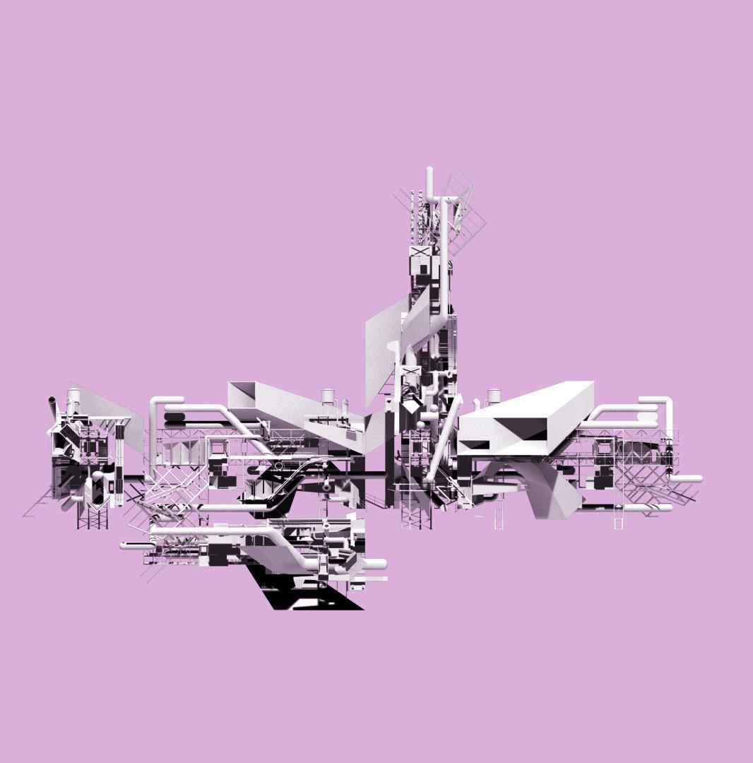
The unfolding of 2D drawings, then generated a new 3D object, where a reciprocity between 2D and 3D visualizations are worked in a new, fresh, way.
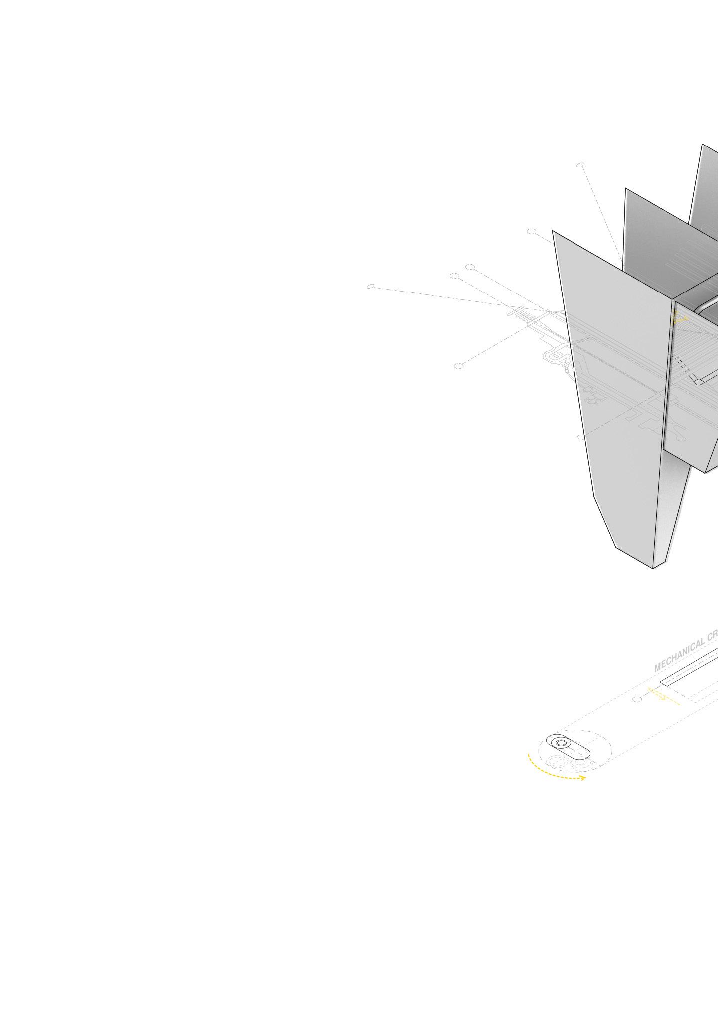
LIBRARY OF PRECEDENTS
Drawing Convention Precedents
a. Plan Wall House #2 - Hajduk
b. Axonometric House III - Eisenman



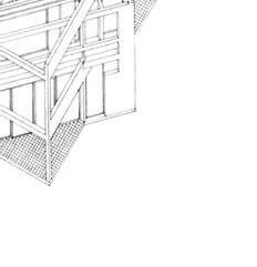

c. Perspective Wexner Center - Eisenman
d. Section - Industrial Oil Pump
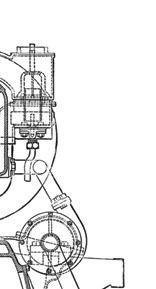
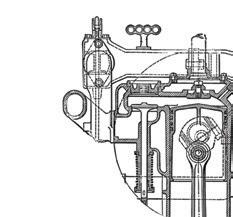
e. Elevation - Typical Stair + Landing
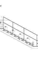
Scale Precedents
f. Building Farnsworth House - Van der Rhoe


g. Urban Partial Brooklyn Grid
h. Instrument Drawing Compass


Bounding Box as TOOL
i. Bounding Box
j. Compilation A + B
k. Compilation A + B Projected
l. 3D Object Visualized
m. Additional Drawings Generated
n. Additional Drawings Projected


Scale: INSTRUMENT
a. Instrument 1 Line
b. Instrument 1 Rendered

Scale: INSTRUMENT
a. Instrument 1 Line
b. Instrument 1 Rendered


Scale: BUILDING
a. Building Composition Line

b. Building Composition Rendered
 b.
b.
Scale: URBAN
a. Urban Composition Line + Render

3D Composition
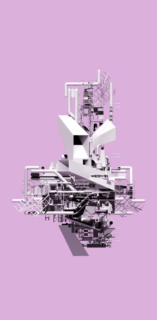
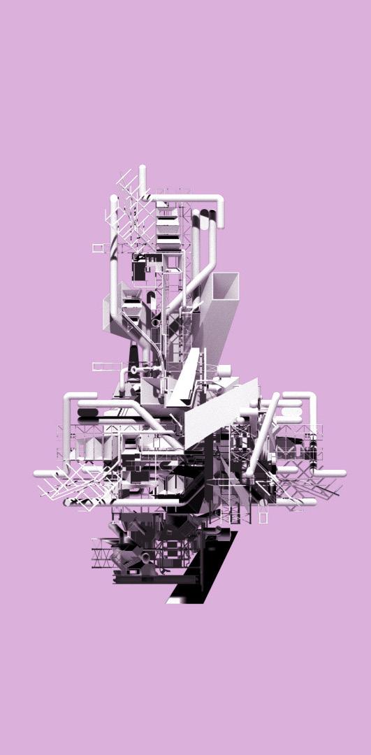
a. Longitudinal View 01
b. Cross View 02
c. Cross View 03
b.


