16 minute read
Mukolyants A. Buranov M. Makhmudov H. Kurbanaliev M

Norwegian Journal of development of the International Science No 44/2020 47 СПИСОК ЛИТЕРАТУРЫ: 11. Lane A.M., Wilson M.G., Whyte G.P., Shave 1. Егупов Н.Д. Методы робастного, нейро– R. Physiological correlates of emotion-regulation durнечеткого и адаптивного управления. М.: Изд-во ing prolonged cycling performance. Appl PsychophysМГТУ им. Н.Э. Баумана. 2002. 744 с. iol Biofeedback. 2011. № 36(3). P.181–4. 2. Гнатовская, А.А., Мещеряков Д.В., Чере- 12. Hallman D. M., Olsson E. M., Von Scheele панова Е.В. Концепция преобразования данных B. Effects of heart rate variability biofeedback in subинфракрасной системой с биологической обратной jects with stress – related chronic neck pain: a pilot связью. Вчені записки ТНУ ім.В.І. Вернадського. study. Appl. Psychophysiol. Biofeedback. 2011. 36. № 2018. 29(68). № 2. С. 116–120. 2. P. 71–80. 3. Сороко С.И., Трубачев В.В. Нейрофизио- 13. Калиниченко А.Н. О точности и достоверлогические и психофизио-логические основы ности спектральных методов расчёта показателей адаптивного биоуправления. СПб.: ИЭФБ РАН. вариабельности сердечного ритма. Информацион2010. 607 с. но-управляющие системы. 2007. № 6.С. 41–48. 4. Плоткин Ф.Б. Компьютерное биоуправле- 14. Filatova A.E. Nonlinear filtration of biomediние: прогрессивные технологии в практику здра- cal signals with the locally concentrated signs in task воохранения. Минск: Новые технологии в меди- of structural identification. Herald of the National цине. 2012. С. 106–110. Technical University "KhPI". Subject issue: Infor5. Федотчев А.И., Бондарь А.Т., Ким Е.В. mation Science and Modelling. – Kharkov: NTU Адаптационное биоуправление с обратной связью "KhPI". 2011. № 17. P. 168–174. и контроль функционального состояния человека. 15. Калиниченко А. Н. Компьютерные методы Успехи физиологических наук. 2002. 33. № 3. С. автоматического анализа ЭКГ в системах кардио79–96. логического наблюдения. Диссертация на соиска6. Акулов С.А., Федотов А.А. Основы тео- ние ученой степени доктора технических наук, рии биотехнических систем. М.: ФИЗМАТЛИТ. Санкт–Петербург. 2008. 205 с. 2014. 259 с. 16. Ajemian R., D'Ausilio A., Moorman H., Biz7. Федотов, А.А., Акулов С.А. Измеритель- zi E. Immediate effect of visual and auditory feedback ные преобразователи биомедицинских сигналов to control the running mechanics of well-trained athсистем клинического мониторинга. М.: Радио и letes. J Sports Sci. 2011. 29(3). p. 253–62. связь. 2013. 250 с. 17. Каплан А. Я. ЭЭГ как управляющий сиг8. Hallman D.M., Olsson E.M., Von Scheele D. нал: на пути к биотехнической нейрокоммуEffects of heart rate variability biofeedback in subjects никации. Биоуправление: теория и практика. Ноwith stress – related chronic neck pain: a pilot study. восибирск. 2010. С. 7–18. Appl. Psychophysiol. Biofeedback. 2011. 36, № 2. P. 18. Косовєров Є.О., Тищук М.М., Мещеряков 71–80. В.І., Веселкова Т.О. Деклараційний патент № 9. Кухтичев А.А., Клёнов Е.А. Носимые 58051А (Україна). Спосіб пелоїдотерапії та камера устройства микроэлектроники как основа биоло- для його здійснення. гической обратной связи системы «ЦифроМед» в 19. Пономарев А.С. Нечеткие множества в заавиации и космонавтике. Врач и медицинские тех- дачах автоматизированного управления и принянологии. 2015. №3. с. 39–48. тия решений. Харьков НПУ “ХПИ”. 2005. 232 с. 10. Wheat A.L., Larkin K.T. Biofeedback of 20. Бодров В.И., Лазарева Т.Я., Мартемьянов heart rate variability and related physiology: a critical Ю.Ф. Математическое программирование. Тамбов, review. Appl. Psychophysiol. Biofeedback. 2010. 35, 2004. 124 с. № 3. P. 229–242.
RESEARCH OF SCHEMES FOR USING ENERGY-SAVING TURBO EXPANDERS INSTALLATIONS IN UZBEKISTAN'S GAS SUPPLY SYSTEMS
Advertisement
Mukolyants A.
Tashkent State Technical University, Docent
Buranov M.
Tashkent State Technical University, Senior Lecturer
Makhmudov H.
Tashkent State Technical University, Senior Lecturer
Kurbanaliev M.
Head of the department of operation of GDS and GIS DEMG
Abstract
The article is devoted to the generally recognized dilemma of using secondary energy resources in the transportation and distribution of natural gas. At stations where throttle devices are used, excessive gas pressure as the main component of secondary energy resources for technological processes is practically not used. Currently, the replacement of throttle devices with turbo-expander units is determined by energy and economic efficiency. This is due to the fact that the use of excess gas pressure in the turbo expander both at gas distribution stations and at compressor stations of gas pipelines without preheating has not yet been widely used. The combi-
48 Norwegian Journal of development of the International Science No 44/2020 nation of expander-generator units with heat pump units contributes to the creation of highly efficient power generating complexes that can generate electricity without burning fuel.
Keywords: main gas pipeline, transported natural gas, gas distribution station, process differential pressure, expander generator, heat pump installation, power generation.
Introduction. One of the most significant problems of our time, The problem of energy conservation, being one of the most important in all developed countries, is becoming especially acute in Republic Uzbekistan. And this is not accidental, because with the growth of the economy and the standard of living of the population, the need for energy has also increased. So, lately, the generating capacities of the country's system have noticeably increased. A 300 MW power unit at the Novo-Angren Thermal Power Station (TPS), a 800 MW unit at the Talimarjan TPP were commissioned, a project to expand the Navoi TPS with the construction of a gas-vapor unit (GVU) with a capacity of 478 MW was implemented, and a cogeneration gas turbine unit was introduced at the Tashkent Heat and Power Stantion with a capacity of 27 MW.
One of the promising approaches to save energy is the use of expander-generator units (EGU) for the production of electricity through the use of technological pressure difference of the transported natural gas. Nonetheless, to date, no practical measures have been taken for the large-scale and effective practical application of this technology in the Central Asian republics, including the Republic of Uzbekistan. Respectively, for uninterrupted power supply of the linear part of gas pipelines, gas meters at gas distribution stations (GDS), gas distribution points (FRP) and other gas supply facilities, the authors consider it more than appropriate to use (EGU) to generate clean electricity through the use of compressed completely natural gas energy.
The effectiveness of the EGU depends on the method of heating the gas in front of the expander.
In [1-2], various methods of gas heating using EGU and the issues of determining the energy efficiency of using EGU are considered. It is shown that when choosing a gas heating system, it is necessary to take into account how gas is used after expansion in the expander, as well as how changing the gas parameters affects the performance of gas-consuming equipment.
In [3–4], the use of EGU in industry is considered, and the distinguishing characteristics of kinetic and volumetric machines are given.
In [5-6], the possibility of using EGU in boiler rooms is described. Various options for heating the gas in front of the EGU are considered: direct network water, flue gases, or using a heat pump installation, to ensure the operation of which part of the electricity generated by the EGU is used. The advantages and disadvantages of each of the considered methods of gas heating are revealed, an exergy analysis of the proposed schemes is carried out. The influence of EGU on the energy efficiency of boiler houses under variable operating conditions is analyzed and an economic assessment of the use of EGU in boiler rooms is given.
This article discusses the main indicators of the installation, in which the gas is heated using a heat pump.
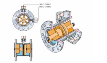
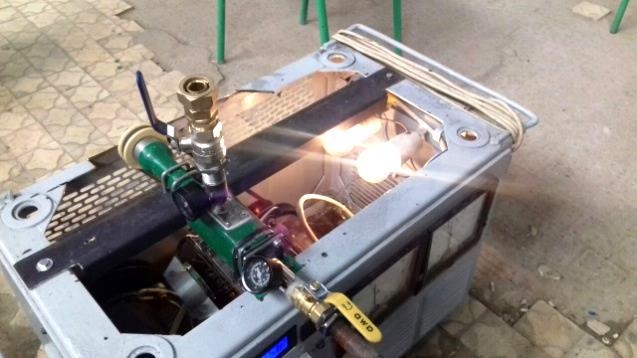
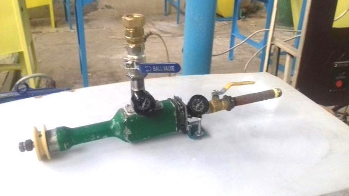
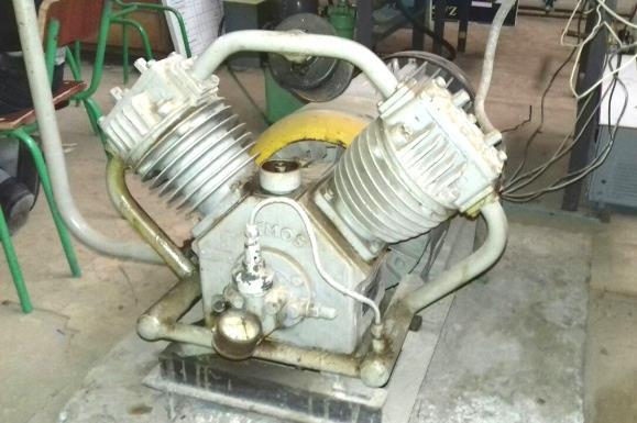
Fragments of the installation for research are presented in Fig. 1a,b,c,d.
Research methods and results. The work and indicators of EGU are considered in two versions: 1) Turning on of EGU without changing the gas consumption for gas consuming equipment; 2) Turning on of EGU affects the gas flow to gas consuming equipment and varies in proportion to the change in the available heat of the gas, taken equal
where
lower calorific value of the gas, – gas enthalpy at given temperature and pressure and at 00С and pressure 0.1 MPa, respectively.
In option 2), the specific change in the gas flow
rate
to the gas-consuming unit at EGU start-up is also determined:
where:
grid; - net power delivered to the power - change in gas flow.
a
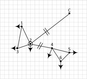
In Fig. 2. the scheme of gas heating before EGU shown. A part of the energy generated by EGU is used to drive the HPU compressor.
The performance parameters of this unit are determined by selection of a refrigerant which provides the required gas temperature.
Let's investigate the case when a change in the enthalpy of gas at the inlet to a gas-consuming installation does not cause a change in gas flow.
Due to the fact that the change in gas flow rate to a gas-consuming installation =0 , then the b
c
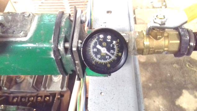
Fig.1. Fragments of the installation for research
by low-grade heat using a heat-pumping unit (HPU) is
d specific change in gas flow rate to generate electricity at the unit in Fig.2
The amount of heat supplied to the gas, equal to: is
where: - gas flow; , - gas enthalpy before heat exchanger 3 (Fig.2) and before expander, respectively.
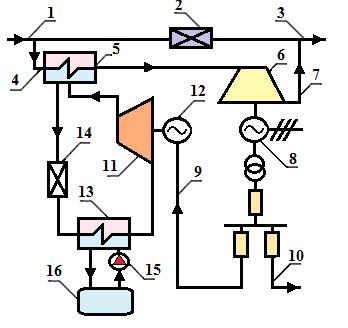
Fig.2. The technological scheme of the installation with an expander-generator unit and a heat pump for heating gas in front of the expander: 1 - high pressure gas pipeline; 2 - throttling device; 3 - low pressure gas pipeline; 4 - high pressure gas supply to the expander; 5 - gas heat exchanger in front of the expander; 6 - turboexpander; 7 - low pressure gas pipeline at the outlet of the expander; 8 - electric generator; 9 - line for supplying electricity to an electric motor drive a compressor; 10 - line for supplying electricity to the power grid; 11 - compressor; 12 - electric motor compressor drive; 13 - evaporator; 14 - throttling device; 15 –pump of heat carrier supply of heat of low temGΔGSP 0.q SUP ,QSUP G 1 0= ( - ),Q G h h GG0h1h perature potential; 16 - heat source of low temperature potential.
where - heat transfer coefficient.
The fraction of EGU power spent on compressor drive is determined by the following expression:
where – gas enthalpy after expander.
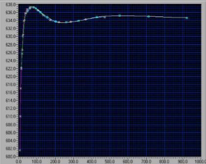
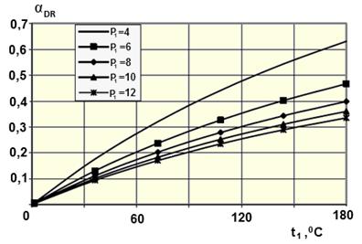
Dependence of the fraction of EGU power spent on compressor drive on the temperature of gas heating before the expander at different initial gas pressures is shown in Fig. 3a and heat transformation coefficients are shown in Fig. 3b.
The fraction of power supplied to the power grid will be equal to
When h0=h2
will be equal to: i.e. depends only on the parameters of the heat pump, the useful power
If h0≠h2, gas flow to the gas-consuming installation changes, and the formula for determining the useful power of the unit will be as follows:
SUP G 1 0 C ( - ) = = , φ φ Q G h hN φ DR α , C 1 0 DR EGU 1 2 ( - ) α = = , ( - ) φ N h h N h h 2hGRIDαEGU C 0 2 GRID EGU 1 2 - ( - ) (φ-1) α = = + . φ φ ( - ) N N h h N h h GRID (φ-1) α = , φ UNITN UNIT EGU C G 1 2 DR = - = ( - ) (1-α ).N N N G h h W 0 L 0 1 0 UNIT G 1 2 W 0 L 2 1 2 + - ( - ) = ( - ) 1- . + - ( - ) φ Q h h h hN G h h Q h h h h
a) at various gas pressures (φ = 4)
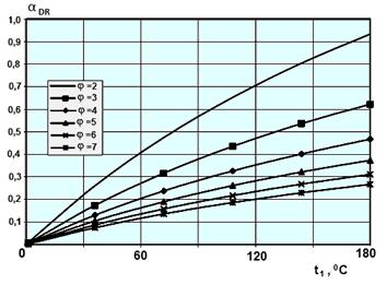
b) for various φ (p1 = 6 kg / cm2) Fig.3. fraction of EGU power spent on HPU compressor drive
and specific change in gas flow for electricity generation:
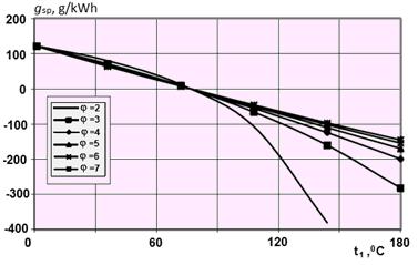
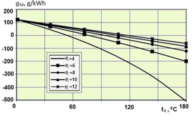
The graphs in Fig. 4 show the results of calculating the dependence of specific change in gas flow on the temperature of gas heating before the expander for various φ (Fig. 4a) and initial gas pressures (Fig. 4b).
а) for various φ and p1 = 6 kg / cm2
b) for various p1 and φ = 4 Fig.4. Dependence of specific change in gas flow on the temperature of gas heating
It should be noted that if h0<h2, then the gas flow rate to the gas-consuming installation will decrease, and when attributing the change in gas flow rate to EGU, the specific change in gas flow rate will be less than 0.
The mathematical model of the unit with singlestage expander-generator units and vapor compression heat pump units is presented as follows.
The object of simulation is a fuel-free installation for generating electricity on the basis of an expandergenerator unit and a steam compression heat pump, shown in Figure 1. The main elements of the simulation object are: expander 6 and generator 8, evaporator 13, compressor 11 with electric motor 12 for its drive and a capacitor 5 of HPU, gas pipelines 1 and 3 of high and low pressure, a source of low potential heat 16.
0 2 G G W 0 L 2 Δ = , + h h G G Q h h 0 2 SP W 0 1 0L 0 1 2 1 2 1 1 = . ( - )+ - - 1( - ) φ h h q h hQ h h h h h h
Norwegian Journal of development of the International Science No 44/2020
Heat pump unit:
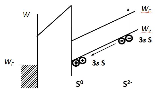
Mathematical description of HPU evaporator: - heat transferred by the low potential heat carrying medium to the refrigerant:
- heat received by the refrigerant from a low potential source:
Mathematical description of HPU condenser: - heat transferred by the refrigerant to the transported gas:
- heat received by the transported gas from the refrigerant:
Equations for determining the flow rate of the refrigerant in the HPU circuit:
or
Power consumed by HPU compressor:
Expander-generator unt: Power generated by EGU:
or
Gas temperature at EGU outlet:
where k is the adiabatic coefficient for the transported gas. Electricity supplied to the power grid:
Share of electricity supplied to the power grid:
Algorithm for calculating installation parameters with single-stage EGU and vapor compression HPU.
1. Gas temperature at EGU outlet is calculated from the known enthalpy and pressure:
2. Gas temperature at EGU inlet is calculated from the equation:
Coefficient in the first approximation is set equal to , then the calculation is performed by the method of successive approximations. 3. Power generated by the EGU is calculated from the expression:
LPHS 10 11 10( )Q G h h )( 96ref10 hhGQ 3 ref 7 8( )Q G h h 3 g 4 3( ).Q G h h HE 3 ref 7 8 ( ) QG h h )( 96 10 ref hh QG ref 7 6 8 EM ( ) . G h h N EM2 g 4 5( )N G h h EM 1 5 2 g 4 4 4 о 1 . 1 k k g i pk N G R T z k p 5 1 4 5 4 4 5 1 1 k k oi z T T p p z 7 2 8.N N N 2 8 2 . N N N ),( hpft 5 1 4 4 4 5 5 . ( ) 1 1 k k oi T T z p p z 4z5z
4. Gas enthalpy at the inlet and outlet of the gas preheating heat exchanger is calculated:
5. Thermal energy required to heat the gas to a predetermined temperature is calculated from the equation:
6. Refrigerant temperature at HPU compressor outlet is calculated:
7. Refrigerant temperature HPU condenser outlet is calculated:
8. Refrigerant temperature HPU evaporator outlet is calculated:
9. Refrigerant parameters at all points in the HPU circuit are calculated:
10. Refrigerant flow rate in the HPU circuit is calculated:
11. Power required to drive the HPU compressor is calculated:
12. Flow rate of the heat-carrying medium from the low potential heat source is calculated:
13. The share of electricity supplied to the power grid is calculated:
Conclusion. Based on all of the above, we can come to the following conclusion: the obtained dependences make it possible to calculate the useful power of a EGU, in which HPI is used to heat the gas before the expander, and the use of a heat pump installation to heat the gas before the expander allows not only to obtain electricity without burning additional gas, but also to reduce gas consumption at the gas-consuming installation due to increase the physical heat of the gas.
REFERENCES:
1. A A Mukolyants, M D Buranov, I V Sotnikova and H F Makhmudov. Operation analysis of expander-generator unit at a gas distribution station. Journal of Physics: Conference Series. 2020. Journal of Physics: Conference
g g EM 1 4 2 4 4 5 . 1 1 k k oi pk N G R T zk p ( , ).h f p t g 3 4 3( ).Q G h h 7 4 1.t t 8 3 2.t t 6 11 3.t t )(),(),( 666666 tfstfptfh 78888 ),,( ppptfh 8 9.h h ref HE 3 7 8 .( ) QG h h ref EM 7 6 8 . ( )G h hN ref LPHS HE 7 9 11 10 . ( ) ( ) G h h G h h 2 8 2 . N N N oi hhhhstfhstfpss 67 6777777767 id idididid ),,(),,(,
Series 1515 022053 https://doi:10.1088/17426596/1515/2/022053. 2. Agababov V 2004 J. News of Higher Education Institutions, Energy issues B 7 50-60. 3. Buranov M., Mukolyants A. and Sotnikova I. 2019 J. Phys.: Conf. Ser. 1399 055038 doi:10.1088/1742-6596/1399/5/055089. 4. Agababov V., Koryagin A., Utenkov V. and Khaymer Yu. 2000 J.Gas-Erdgas gwf. B 9 610-615. 5. R. Gambhire 2014 J. International journal of innovative research in science B 3 293-300. 6. Mukolyants A.A., Buranov M.D., Sotnikova I.V., Makhmudov H.F. The expander-generator unit at a gas distributing station of magistral gas pipeline. The collection includes 16th the International Scientific and Practical Conference “Science and Socienty” by SCIEURO in London 23-28 February 2020.