12 minute read
Helicopter Fueling Facilities


7
Helicopter Fueling Facilities
Advertisement
7.1 General
This section outlines the requirements for the storage and transfer of Jet Ai fuel. When developing fueling arrangements, consideration should be given to the type of fuel on which the helicopter to be operated is run. In addition, all facilities for the storage and handling of aviation fuels on board should be grade identified using the appropriate American Petroleum Industry (API) markings for the grade of fuel used. Aviation fuel facilities should also be fully segregated from any other fuel system.
7.2
Refueling and defueling operational considerations should be agreed with the helicopter pilot/operator and Aviation Inspection Body.
7.3
The following plans and particulars are to be submitted to the Aviation Inspection Body and Classification Society for approval: .1 Description of fuel with statement of minimum flash point (closed cup test); .2 Arrangement of fuel storage and piping; .3 Arrangements for drainage, ventilation and sounding of spaces adjacent to storage tanks; .4 Details and approval certification of pumping units; .5 Structural fire protection arrangements of all spaces to contain aviation fuel; .6 Fire detection and extinguishing arrangements; .7 Ventilation arrangements.
7.3
Attention is also drawn to section 14.1 above which addresses "Protection of spaces containing vehicles or craft with fuel in their tanks or lockers storing such fuels."
7.4
When developing operational procedures for the movement of aviation fuel onboard, the restricted use of radio frequency equipment including portable phones with regard to transmission sparks should be considered.
7.5 Storage of Aviation Fuel
7.5.1 Fuel storage tanks should be of baffle-free, stainless steel, cylindrical construction, located in a designated area as remote as practicable from machinery and accommodation spaces, and be suitably isolated from areas where there are sources of ignition.
7.5.2 Fuel storage tanks should be provided with an intrinsically safe level indicator fitted through the top of the tank, and a 3f4 inch sampling valve at the bottom of the tank (low end) to allow for samples to be taken as per paragraph 7.8.3 of this section. The minimum slope of the tank to the sampling point should be 1:30.
7.5.3 The storage and handling area should be permanently marked. Instructions for filling fuel and, if appropriate, emptying fuel, should be posted in the vicinity of the filling area.
7.5.4 Tank ventilation (breather) pipes should be fitted with an approved vent head with pressure-vacuum valve, flame arrester, and desiccant. The vent outlet should be located no less than 2.3m above the weather deck in a safe position away from accommodation spaces, ventilation intakes and equipment that may constitute an ignition hazard. Particular attention should also be directed to the height of the tank vent and overflow with respect to the design head of the tank.
7.5.5 High level alarm arrangements should be provided to indicate when fuel storage tanks are close to being filled in excess of maximum operating levels. Alternative arrangements for tank venting may be accepted subject to approval from the Administration.
7.5.6
A coaming surrounding the fuel storage tanks, associated piping and the pumping unit should be provided. The height of this coaming should be at least 150 mm, so as to contain fuel spillage as well as fire extinguishing agents. Where the pumping unit is situated at a remote distance from the fuel storage tank, a separate coaming of the same minimum height should be provided around the pumping unit. For tanks forming an integral part of the vessel's structure, cofferdams with permanently fitted gas detectors should be provided as necessary to contain leakage
and prevent contamination of the fuel. Also, it should be ensured that there is no common boundary between the fuel storage tank and accommodation or high fire risk spaces.
7.5.7 Arrangements for drainage from within the coaming area described in 7.5.6 above should be as follows . .1 Permanent piping and a suitable holding (waste) tank (compliant with 7.1 and 7.5 ) should be fitted so that drainage can be either led to the holding tank (for draining fuel) or discharged overboard (for draining water) through a three-way valve. No other valve should be permitted in the drain piping. The holding tank should be clearly labeled to distinguish between itself and the main storage tank . .2 The cross sectional area of the drain pipe should be twice that of the storage tank outlet pipe . .3 The area within the coaming should be sloped towards the drain pipe.
7.5.8 Drainage of cofferdam spaces should be entirely separate from the machinery space drainage arrangements. As far as is practicable, fuel sampling points should be low points on piping and should provide a "closed sampling" visi-jar system fitted with arrangements to prevent the spring-loaded valve from being locked in an open position.
7.5.9 Air pipes for the cofferdam space should be led to a point at least 2.3m above the weather deck through a safe space and fitted with an approved air pipe head fit for purpose and having a wire gauze diaphragm of corrosion resistant material.
7.5.10 Access to each cofferdam should be provided by at least two manholes from the open deck, each fitted with gas-tight manhole covers. Cofferdams should be cleaned prior to opening manhole covers, using an induced draught certified safe ventilation fan for a minimum of 20 minutes. A notice to this effect should be fitted to each manhole.
7.6 Fuel Pumping and Storage Tank Filling
7.6.1 All tank outlet valves and filling valves should be mounted directly onto the tank and be capable of being closed from a remote location outside the compartment in the event of a fire in the compartment. Ball valves are to be of the stainless steel, antistatic,
fire tested type.
7.6.2 If more than one storage tank is fitted then fuel should be pumped through suitable filtration if it is to be transferred from one tank to another.
7.6.3 Filling arrangements for fuel tanks should be through closed piping systems with outlet ends configured to reduce turbulence and foaming of the fuel. If the storage tank(s) are filled from the top, the filler pipe should pass through the tank to the bottom and terminate with a 90 degree bend so that fuel flows over the bottom of the tank to reduce the possibility of a build-up of static charge.
7.6.4 Pumping units should be easily accessible and capable of being controlled from both the fuel station and a position remote from the fuel station. The device to prevent over-pressurization as required by SOLAS 11-2, Regulation 4 .2.2.4 should be fitted with a relief valve to discharge either to the suction side of the pump(s) or to a holding tank complying with the arrangements of 7.5 of this section.
7.6.5 When not in use, fuel filling equipment should be stowed in a locker that is well ventilated and drained.
7.6.6 Suitable filtration arrangements in accordance with appropriate American Petroleum Industry (API) and British Energy Institute (or equivalent) standards should be provided to reduce the level of water and particulate contamination of the fuel to within the limits specified by the helicopter manufacturer. The minimum requirements are; delivery into storage through a filter water separator (FWS), filtration out of storage through filter water separator (FWS), filtration at the point of filling (e.g. on the helicopter landing area), via a filter monitor (FM). Filter vessels should be fitted with a differential pressure gauge and automatic air eliminator.
7.6.7 In general, all piping systems should be located clear of accommodation spaces, escape routes, embarkation stations and ventilation openings and should not pass through category A machinery spaces. However, where arrangements are such that piping has to pass through accommodation spaces, service spaces, escape routes, or embarkation stations double skinned piping is to be used or pipes should be enclosed in a cofferdam.
7.6.8 Means should be provided for keeping deck spills away from accommodation and service areas.
7.6.9 Drip trays for collecting replenishment oil residues in pipelines and hoses should be provided beneath pipe and hose connections in the manifold area. Drainage should be designed and constructed in order to avoid leakage overboard.
7.6.10 It is recommended that a "Y" strainer should be fitted on the pump suction to protect the pump itself.
7.7 Refueling and Defueling Helicopters
7.7.1
Refueling and defueling hoses should be of one continuous length, smooth bore, synthetic rubber construction, and semi-conducting, conforming to EN 1361 type C or API standards. A hose end pressure controller should also be provided for fueling hoses to prevent the possibility of the helicopter fuel tanks being subject to excessive pressure. Delivery Nozzles should be fitted with minimum 100 mesh strainer element, and in the case of gravity over-wing nozzles, they should be situated in the spout. Trigger mechanisms should not have hold-open ratchets.
7.7.2
Provision should be made to electrically bond the helicopter to the vessel prior to commencement, and throughout the process of, any refueling and defueling procedures. The maximum resistance of such bonding systems should be less than 0.5 ohms.
7.7.3
Where appropriate CCTV should be used to ensure full view from the bridge of all helicopter refueling activities that would normally be hidden from view.
7.8 Prevention of Fuel Contamination
7.8.1 Materials and/or their surface treatment used for the storage and distribution of fuel should be selected such that they do not introduce contamination or modify the properties of the fuel. The use of copper or zinc compounds in fuel piping systems where they may come into contact with fuel is not permitted. Copper-nickel materials are permissible but should be limited to positions after filtration and water absorption equipment.
7.8.2 The location and arrangement of air pipes for fuel tanks are to be such that in the event of a broken vent pipe, this does not directly lead to ingress of seawater or rain water.
7.8.3 Fuel samples should be taken on a daily basis throughout the fuel handling, storage, and distribution process from the tank in use, all filter vessels, and at the hose end. Fuel samples should be recorded and kept for 24 hours in a 1 US Gallon glass jar then disposed of in the aviation fuel waste/holding tank referred to in paragraph
7.5.7 A record should be kept of all fuel movements on board. Guidance on how to take fuel samples and record fuel movements may be obtained from Chapter 4 of UK CAA CAP 748 which is accessible via the UK CAA website www.caa.co.uk. Fuel in the holding tank may be passed to the main tank provided that suitable filtration in accordance with paragraphs contained within 7.6 and to the satisfaction of the aviation inspection body.
7.8.4 At least one member of crew on-board the vessel should be trained in the handling of aviation (JetA1) fuel and associated quality control procedures. This person(s) should oversee all operations involving the movement of aviation fuel on-board. Further guidance on such training may be obtained from the fuel supplier and marine aviation consultants.
7.9 Fuel Pumping Spaces/Compartments
7.9.1 Where it is intended to install fuel transfer pumps for handling aviation fuel in a separate compartment, the pump room(s) should be totally enclosed and have no direct communication, through e.g. bilge piping systems and ventilation systems,
with machinery spaces; should be situated adjacent to the fuel storage tanks; and should be provided with ready means of access from the weather deck.
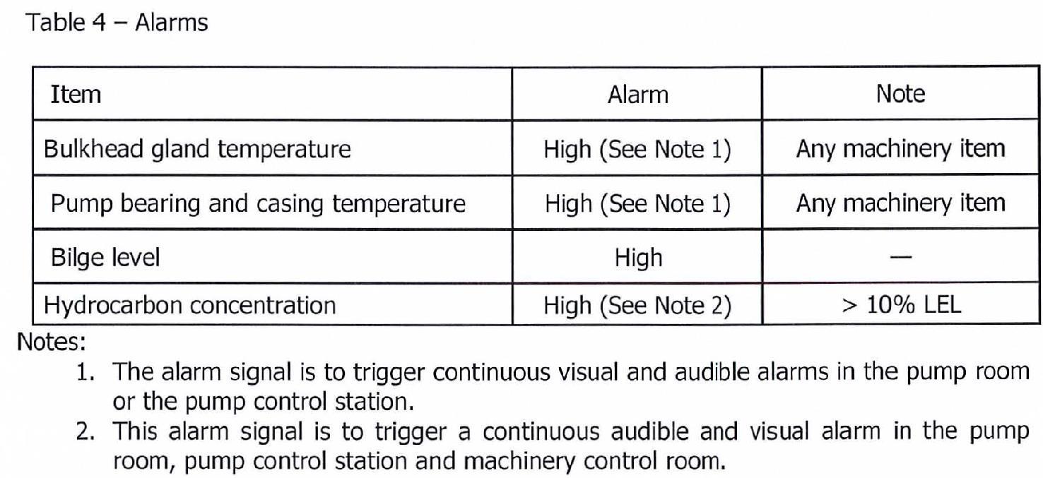
7.9.2 Alarms and safety arrangements should be provided as indicated in 7.5.5 and Table 4, below.
7.9.3 A system for continuously monitoring the concentrations of hydrocarbon gases within the pump room should be fitted. Monitoring paints are to be located in positions where potentially dangerous concentrations may be readily detected.
7.10 Ventilation
7.10.1 Fuel pump room(s), fuel storage room(s) and other closed spaces which contain fuel handling equipment, and to which regular access is required during fuel handling operations, are to be provided with permanent ventilation system(s) of the mechanical extraction type.
7.10.2 The ventilation system(s) should be capable of being operated from outside the compartment being ventilated and a notice should be fixed near the entrance stating that no person is to enter the space until the ventilation system has been in operation for at least 15 minutes.
7.10.3 The ventilation system(s) should be capable of 20 air changes per hour, based on the gross volume of the pump room or space.
7.10.4 Protection screens of not more than 13 mm square mesh should be fitted in outside openings of ventilation ducts, and ventilation intakes should be so arranged as to minimize the possibility of re-cycling hazardous vapors from any ventilation discharge opening. Vent exits are to be arranged to discharge upwards.
7.10.5 The ventilation should be interlocked to the lighting system (except emergency lighting) such that the pump room lighting may only come on when the ventilation is in operation. Failure of the ventilation system is not to cause the lighting to go out and failure of the lighting system is not to cause loss of the ventilation system.
7.11 Non-Sparking Fans for Hazardous Areas
7.11.1
The air gap between impeller and housing of ventilation fans should be not less than 0.1 of the impeller shaft bearing diameter or 2 mm whichever is the larger, subject also to compliance with 7.3. Generally, however, the air gap need be no more than 13 mm.
7.11.2
The following combinations of materials are permissible for the impeller and the housing in way of the impeller: .1 Impellers and/or housings of non-metallic material, due regard being paid to the elimination of static electricity . .2 Impellers and housings of non-ferrous metals . . 3 Impellers and housings of austenitic stainless steel. .4 Impellers of aluminum alloys or magnesium alloys and a ferrous housing provided that a ring of suitable thickness of non-ferrous material is fitted in way of the impeller. .5 Any combination of ferrous impellers and housings with not less than 13 mm tip clearance . . 6 Any combination of materials for the impeller and housing which are demonstrated as being spark proof by appropriate rubbing tests.
7.11.3 The following combinations of materials for impellers and housing are not considered spark proof and should not be permitted: .1 Impellers of an aluminum alloy or magnesium alloy and a ferrous housing, irrespective of tip clearance . . 2 Impellers of a ferrous material and housings made of an aluminum alloy, irrespective of tip clearance . . 3 Any combination of ferrous impeller and housing with less than 13 mm tip clearance, other than permitted by 7.3.
7.11.4
Electrostatic charges both in the rotating body and the casing should be prevented by the use of antistatic materials (i.e. materials having an electrical resistance between 5 x 10⁴ ohms and 108 ohms), or special means should be provided to avoid dangerous electrical charges on the surface of the material.
7.11.5 Type approval tests on the complete fan should be carried out to the satisfaction of the Classification Society.
7.11.6 Protection screens of not more than 13 mm square mesh should be fitted in the inlet and outlet of ventilation ducts to prevent the entry of objects into the fan housing.
7.11.7
The installation of the ventilation units on board should be such as to ensure the safe bonding to the hull of the units themselves.


