

ROCKFORD BULKHEAD LUMINAIRE INSTRUCTIONS
Issue 04 on 6th April 2022
THANK YOUfor buying this product. To helpensure it gives complete satisfaction pleaseinstall it according totheseinstructions and then pass the instructions tothe appropriate person forretentionand future reference.
SAFETY This is a mains powered product. It is designedto beinstalled by suitably qualified personnel only and in accordancewiththe applicablebuilding and electrical regulations. Before installation or maintenancethe electrical supply tothe product must be isolated.

INSTALLATIONSUPPORT If installationadvice or accessories arerequired pleasecontact us at the above address. Wewill doour best to help. When reporting a suspected fault or seekinginstallationsupport the problem is likely to beresolvedmost quickly ifyou havefull product details to-hand, as well as details of when and whereit was purchased.
INSTALLATION


1. Removethe mounting bracket, bypressingthe release mechanisms on eitherside Fig 1.

2. Prepare themains supply cable&fixing points onthechosen mounting surface ensuring it can retainthe weight of the luminaire. Fig 2.
Note! It istheinstaller’s responsibility to ensurethe fixing points & cableentry pointare appropriately sealed to maintain therating
3. Route themains supply cabletothe terminal block on thebase& terminate ensuringcorrect polarity isobserved Fig 3. & Fig4. Note! Thisis a ClassII luminaire, so no earthis required.
For M3 Versionssee terminal block wiring as shown


4. Select the required CCT usingtheslider switchin thebase:
WW = WarmWhite = 3000K
NW = Neutral White =4000K
CW = Cool White = 5700K
For MD versions only..
It is for the installer to ensure that any dimmer used with this fitting is compatible with it. NVC cannot guarantee the performance of another manufacturer’s products but we have found that the following dimmers,used in accordance with the manufacturer’s guidance, give a performance that we consider to be good (others are available):
HamiltonL400/G AuroraAU-DSP400X BG60-400W Muudi1A60010-300W
Varilight Crabtree60-250W V-PRO250W ELKO315GLE20-315VA
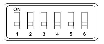
For MW versions only
1. set the DIP switches as shown below.
2. Snap fit themain body onto the mounting bracket Fig 5.
3. Reconnect power supply & check for correct operation.
Note! Luminaires fitted withelectronic drivers areexempt from insulation resistance tests as this may cause damage to the components.
Integrated Microwave Sensor Versions Only :-
Switch default settings:
SensorSettings


Detection Area – sensitivity can be adjusted if required.
Hold time – is the time the the luminaire will remain at 100%, adjustable from 5s to 10mins.
Daylight Sensor - can be set to operate at 30 lux or disabled for just motion detection.
Stand-by Dim Level – if required can be dimmed to 0% or 20% when no further presence is detected.
Standby-by Period –this is the time period the low output level is maintained for before the luminaire is turned off.


GENERAL MAINTAINED EMERGENCY LUMINAIRE INSTRUCTIONS (SUFFIX .../M3)
These instructions should be followed in conjunction with the standard luminaire instructions. Please read carefully and pass to the end user/responsible person for retention and future reference.
INSTALLATION
1. Following the installation of the luminaire in accordance withthe standard luminaire installation instructions, a separate permanent live supply should beterminated in the 4-poleterminal block in the luminaire, in the connection marked ‘L PERM’. The permanent supply MUSTbe taken from the same phaseas the corresponding switched supply and MUST be wired at the switchboardso that upon instances of tests, it is isolated at the same time as the switched supply.
2. Connect the battery to the module via the ‘plug and mate’ connector, ensuring correct polarity is observed. Failure to observe correct battery polarity will result in permanent damageto the emergency module/driver.
3. Upon restoration of the power supply to the luminaire, check that the indicatorLED fitted within the luminaire illuminates green. This indicates that the batteries are charging and that the charging circuit is healthy.
4. Allow the battery to charge for an uninterrupted period of not less than24 hours prior to carrying out a full discharge test.
MAINTENANCE
5. The battery pack in this luminaire must be replaced when it is no longerable to satisfy its full rated duration.
6. In emergency mode the light levelof the luminaire will be at a reduced output. Regular maintenance and gentle cleaning is recommended so as to ensure that the Emergency Output Factor (E.O.F)remains atpre-determined levels.
7. Isolate the supply before servicing.
8. DO NOT INSULATION TEST
This unit is usingLithiumIonPhosphatecells (LiFePO4) inits batterypack.These batteries require closemonitoringandprotectioncircuitrytooperate safely. The same‘battery’pack will be requiredwhen exchanging batterypacks inthefutureduring maintenance.
TESTING FOR EMERGENCY LUMINAIRES
Recommended routine test procedures in line with BS 5266-1:2016 & BS EN 50172:2004.