NEPTUNE LED HIGH BAY INSTRUCTIONS
Issue 01 on 19th June 2023
THANK YOU for buying this product. To help ensure itgivescomplete satisfaction please install it according to these instructions and then pass theinstructions to the appropriate person for retention and futurereference.
SAFETY This is a mains powered product. It is designed to be installed by suitably qualified personnel only and in accordance with the applicable building and electricalregulations. Before installation or maintenance the electrical supply to the product must be isolated.
INSTALLATION SUPPORT If installation advice or accessories are required please contact us at the above address. We will do our best to help. When reporting asuspected fault orseeking installation support the problem is likely to be resolved most quickly if you have full product details to-hand, as well as details of when and where it was purchased.


INSTALLATION
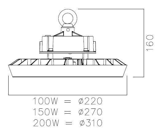
1. Screw suspension eyelet (provided separately in box) into threaded hole on top of the driverunit,then screw in the small safety screw on the side to secure its position
2. Suspend the luminaire via the eyelet onto the chain link.
3. Provide a main supply cable & route to the luminaire.
4. Connect the mains supply cable to the pre-wired luminaire supply cable using an IP65 min. rated connection box/connector, ensuring correct polarity is observed.
5. Reconnectpower supply & check for correct operation. Note! Luminaires fitted withelectronic drivers are exempt from insulation resistance tests as this will cause damage to the electronic components.


MAINTENANCE
1. Gentle cleaning of the PC clear panel witha soft cloth should be carried out at regular intervals so as not impair photometric performance of the luminaire.
2. Heat sink on rear of product shouldbe kept clear of dust & dirt or it will affect the heat dissipation. This may reduce rated lifetime of the product.
LENS ATTACHMENTS (OPTIONAL EXTRA)
1. The Neptune range has optional Lens attachments available in 60° & 90° for each variant
2. If the Lens attachment has been purchased it can be installed as follows:
Remove the clear PC panel by undoing the screws.

Offer up the required lens option, locate &secure using the same screws
Note! The lens are size specific to the wattage of the luminaire. Ensure you have the right size

STRIRRUP MOUNT BRACKET (OPTIONAL EXTRA)
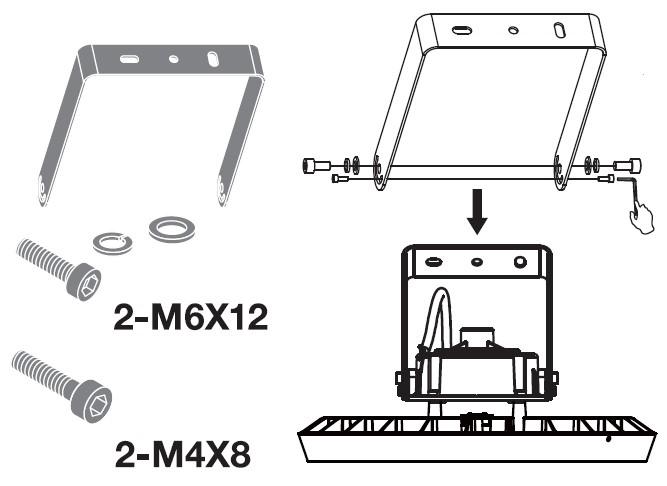
1. Part code:- NNT/SMB (suitable for all variants)
2. Fix directly to the allocated hole positions on the transformer as shownbelow (fig 1.) using the allen key screws and washers provided.
Fig 1.