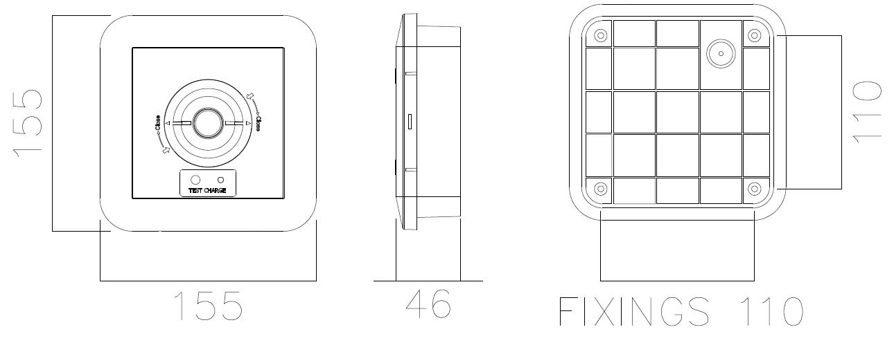
Seneca LiFe LED Surface Square Downlight Black - NSC/BK/SURF/SQ/NM3
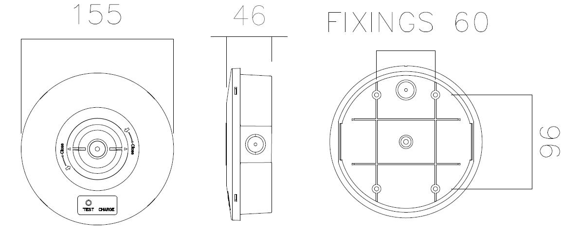
Seneca LiFe LED Surface Circular Downlight Black - NSC/BK/SURF/RD/NM3
THANK YOU - for buying this product. To help ensure it gives complete satisfaction please install it according to these instructions and then pass the instructions to the appropriate person for retention and future reference.
SAFETY - This is a mains powered product. It is designed to be installed by suitably qualified personnel only and in accordance with the applicable building and electrical regulations. Before installation or maintenance, the electrical supply to the product must be isolated.
INSTALLATION SUPPORT - If installation advice or accessories are required, please contact us at the above address. We will do our best to help. When reporting a suspected fault or seeking installation support the problem is likely to be resolved most quickly if you have full product details to-hand, as well as details of when and where it was purchased.
Seneca LiFe LED Surface Square Downlight Black:

Part Code:- NSC/BK/SURF/SQ/NM3
LUMINAIRE INSTALLATION:
Remove the front cover molding by releasing the four clips on the side wall using a flat head screwdriver
1. Prepare the surface & mains supply cable.
2. Route the mains supply cable through the hole in the base & then screw fix the base to the mounting surface using the four fixing points provided at 110mm centers
3. Route the mains supply cable to the terminal block
4. Connect the battery pack to the PCB by connecting the 2-pole female socket on the battery wires to the larger 3-pole male plug mounted on the PCB Ensure correct orientation.
5. Enter the “Commission Date” in the appropriate place on the battery pack label.
6. Offer the front cover to the base & connect:
a. The 2-pole connector to the 2-pole plug on the main PCB labeled “LED-/ LED+”, ensuring correct orientation.
b. The 2-pole test connector to the matching plug on the PCB
7. Refit the front cover molding by snap fixing over the four clips & ensuring there are no wires trapped. Note! There is a location peg that needs to align with a recess in the front cover molding
8. Reconnect the power supply & check the green LED charge indicator illuminates.
9. The batteries should be allowed to charge for at least 24 hours before carrying out a full discharge test to check they are charging correctly & the maintained duration is being achieved.
10. The luminaire operating temperature range is 0⁰C - +40⁰C.


LENS SELECTION:
The luminaire comes fitted with a wide distribution lens as standard.
1. There is an option to change to the oval distribution lens (supplied) by following the below steps:
a. Remove the wide distribution lens by turning it anti-clockwise from the closed position to the unlocked open position (aligned with the two arrows).
b. Locate the oval distribution lens onto the front cover in the unlocked open position (aligned with the two arrows) and turn clockwise to lock the lens into the closed position.
Downlight Black:

Part Code:- NSC/BK/SURF/RD/NM3
LUMINAIRE INSTALLATION:
Remove the front cover molding by releasing the four clips on the side wall using a flat head screwdriver.
11. Prepare the surface & mains supply cable.
12. Route the mains supply cable through the hole in the base & then screw fix the base to the mounting surface using the four fixing points provided at 60mm centers.
13. Route the mains supply cable to the terminal block.
14. Connect the battery pack to the PCB by connecting the 2-pole female socket on the battery wires to the larger 3-pole male plug mounted on the PCB Ensure correct orientation.
15. Enter the “Commission Date” in the appropriate place on the battery pack label.
16. Offer the front cover to the base & connect:
c. The 2-pole connector to the 2-pole plug on the main PCB labeled “LED-/ LED+”, ensuring correct orientation.
d. The 5-pole test connector to the matching plug on the PCB
17. Refit the front cover molding by snap fixing over the four clips & ensuring there are no wires trapped. Note! There is a location peg that needs to align with a recess in the front cover molding.
18. Reconnect the power supply & check the green LED charge indicator illuminates.
19. The batteries should be allowed to charge for at least 24 hours before carrying out a full discharge test to check they are charging correctly & the maintained duration is being achieved.
20. The luminaire operating temperature range is 0⁰C - +40⁰C.
LENS SELECTION:
The luminaire comes fitted with a wide distribution lens as standard.
2. There is an option to change to the oval distribution lens (supplied) by following the below steps:
a. Remove the wide distribution lens by turning it anti-clockwise from the closed position to the unlocked open position (aligned with the two arrows).
b. Locate the oval distribution lens onto the front cover in the unlocked open position (aligned with the two arrows) and turn clockwise to lock the lens into the closed position.


OPERATION / MAINTENANCE:
1. This unit is using Lithium Iron Phosphate cells (LiFeP04) in its battery pack. These batteries require close monitoring and protection circuitry to operate safely. This pack uses a dedicated protection built into the module unit. Ensure like for like batteries are used in any replacement maintenance.
2. Nominal battery life is designed to be at least 4 years. The battery should be replaced when it is no longer able to provide its 3 hours of rated duration.
3. This luminaire MUST be disconnected before the circuit it is installed on is subjected to any high voltage or insulation resistance testing, otherwise irreparable damage will occur to luminaire components.
4. Ensure cleanliness of luminaires is maintained so as not to affect performance.
TESTING FOR EMERGENCY LUMINAIRES:
Recommended routine test procedures in line with BS 5266 & BS EN 50172:
Monthly Functional Test:
• Simulate a mains supply failure by isolating the circuit (ensuring it is safe to do so) or by way of a test key switch if fitted into the circuit.
• Do this for a period of time sufficient to check that the light source illuminates from the battery supply.
• Once complete, ensure the normal supply is restored & that the green LED charge indicator illuminates.
• Log result/comments in the emergency lighting Logbook.
Annual Discharge Test:
• Simulate a mains supply failure by isolating the circuit (ensuring if it is safe to do so) or by way of a test key switch if fitted into the circuit.
• This should be for the full 3-hour rated duration.
• Check that the light source illuminates & remains illuminated for the full rated duration period.
• Once complete, ensure the normal supply is restored & that the green LED charge indicator illuminates.
• Log result/comments in the Testing Logbook.


