Oceane Durand-Maniclas: 201754101
Mana Bakhshandeh :201772731
Arshia Olfat: 201775889

INTEGRATED BIM PROJECT ARCH 745 - BIM INTEROPERABILITY & DESIGN COORDINATION - 23/24
A. STANDARD: ISO 19650 B
BIM & COLLABORATION
C.
INTEROPERABILITY & OPEN BIM: IFC
D. QUALITY CHECKING PROCESS E
OBJECT CLASSIFICATION SYSTEMS
4D SIMULATION F.
CASE STUDIES
A. CASE STUDY 1
B. CASE STUDY 2
METHODOLOGY
FRAMEWORK
A. PROJECT
B. COLLABORATION
C.LESSONS LEARNED
MODEL
A. REVIT MODEL
B. ARCHICAD MODEL
MODEL COMPARAISON
A. GEOMETRY
B. 2D DRAWING & ATTRIBUTES
C.EDITING
D. CONCLUSION
E. LESSONS LEARNED
MODEL CHECKING: SOLIBRI
A. MODEL PREPARATION
B. IFC IMPORT
C. CLASSIFICATION
D. CHECKING
4D SIMULATION: SYNCHRO
A. MODEL PREPARATION
B. IFC IMPORT
C. 3D FILTERING
D. APPEARANCE PROFILE
E. CREATE SCHEDULE
F. ASSIGN TASK
G.CONCLUSION
H. LESSONS LEARNED
LESSONS LEARNED
CONCLUSION
A. LIMITATIONS & POTENTIALS
B. COLLABORATION & SOFTWARE
C. BIM MANAGEMENT
1 C O N T E N T 2 3 4 5 6 7 8 9 10 INTRODUCTION
CREATION
I
A. BIM & COLLABORATION
Building Information Modeling (BIM) has revolutionised the Architecture, Engineering, and Construction (AEC) industries by providing a digital representation of physical and functional properties of the building (C. Eastman et al., 2008a). BIM is a collaborative process allowing architects, engineers, and contractors to work simultaneously on a unified model (C. Eastman et al., 2008a). This model serves as a reliable basis for decisions throughout the building's lifecycle, from conception through demolition (C. Eastman et al., 2008a).
Collaboration through BIM involves to integrate various disciplines' knowledge into one shared model, which is continuously updated and optimised (Eastman et al., 2011). Thus, it prevents errors and discrepancies that could occur when different teams work on a same project (C. Eastman et al., 2008a). Consequently, BIM facilitates realtime communication and coordination among all stakeholders, fostering a cooperative environment that enhances problem-solving and innovative thinking (C. Eastman et al., 2008a).
This leads to increased efficiency and shortened project timelines (Azhar, 2011) , and impact cost, and improved quality of built environments (Succar, 2009).
To help BIM workflow and facilitate collaboration, ISO 19650 is a series of international standard that support a framework for BIM implementation through information management. ISO 19650-2: 2018
B. STANDARD: ISO 19650
The International Organization for Standardization (ISO) 19650 part 1 and 2 has created a comprehensive set of guidelines to support the implementation of building information modeling (BIM) in the UK. Along these guidelines, ISO 19650-2, provide processes for project delivery, which are divided into eight key activities. These activities outline the specific tasks and functions required of individuals working on the project, resource allocation and software utilisation, collaborative data exchange strategy within a Collaborative Data Environment (CDE)Clause 5.6-, use of open format exchange such as (CoBIe, BCF, IFC, etc.), and information model delivery. Additionally, the guidelines provide instructions on naming conventions, timeframes, and delivery strategies to ensure model checking and building quality delivery
In this portfolio, the focus is on the activity six ( Collaborative production of information -ISO 19650-2 Cause 5.6) and seven (Information model delivery -ISO 19650-2 Clause 5 7)
C. INTEROPERABILITY & OPEN BIM: IFC
The information generated by BIM authoring tools can be transferred and reused in other software for various purposes such as feasibility study, coordination, performance simulation, cost estimation, and time management. OpenBIM, introduced by the Alliance for Interoperability (BuildingSmart), is based on open standards and workflows and facilitates the realization and operation of buildings (Djouja et al,. 2019). ISO 19650 Guidance B highlights the importance of using Open data and Industry Foundation classes (IFC) to ensure consistent information sharing. IFC is a standardized, object-oriented terminology and a common data model format (Djouja et al,. 2019). It also includes four other methodology standards: Information Delivery Manual (IDM), BIM Collaboration Format (BCF), International Framework for Dictionaries (IFD), and Model View Definitions (MVD) (Djouja et al,. 2019).
In this portfolio, IFC will be used as the pilot format between the software used.
1
N T R O C U C T I O N
1
I N
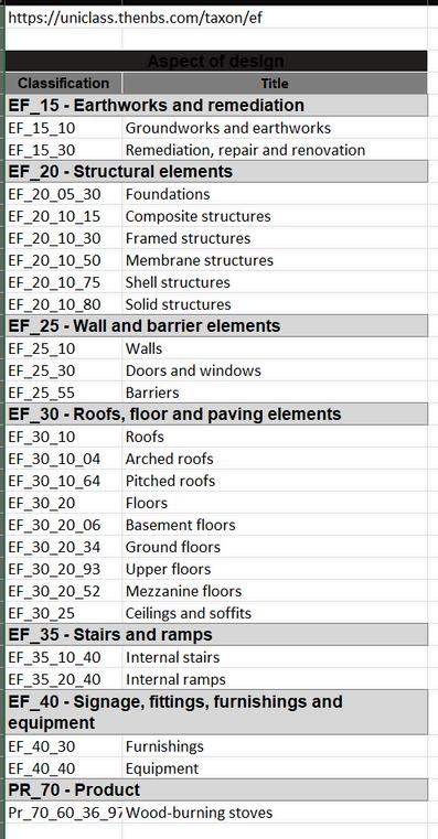
D. OBJECT CLASSIFICATION SYSTEM
BIM projects differ from traditional CAD-designed ones by storing detailed information about products and systems used. Classification systems ensure this data remains useful beyond the project file. If data isn't well-organized for later retrieval, it loses value for specification, construction, and project management teams (Weygant, 2011, p.168).
So Making the most out of information models in BIM projects depends on how good the data is and how well BIM objects are named and categorized. Classification systems like Uniclass 2015 and NRM are created to give users a consistent way to assign characteristics to objects in BIM models. they provide common ways to name BIM objects. But the information needed can vary based on who's using it, the project's size, and where it's at in the delivery process (Rogage and Doukari, 2024, p. 3, 4). Some popular classification systems are MasterFormat, UniFormat, Uniclass and OmniClass. Project stakeholders utilize them differently. Owners organize data for facility management, planning, and cost estimates. Contractors employ classifications in construction management, scheduling, and cost estimates. Architects and Engineers use classifications to generate project specifications (Autodesk, no date-a, P. 5).
E. QUALITY CHECKING PROCESS
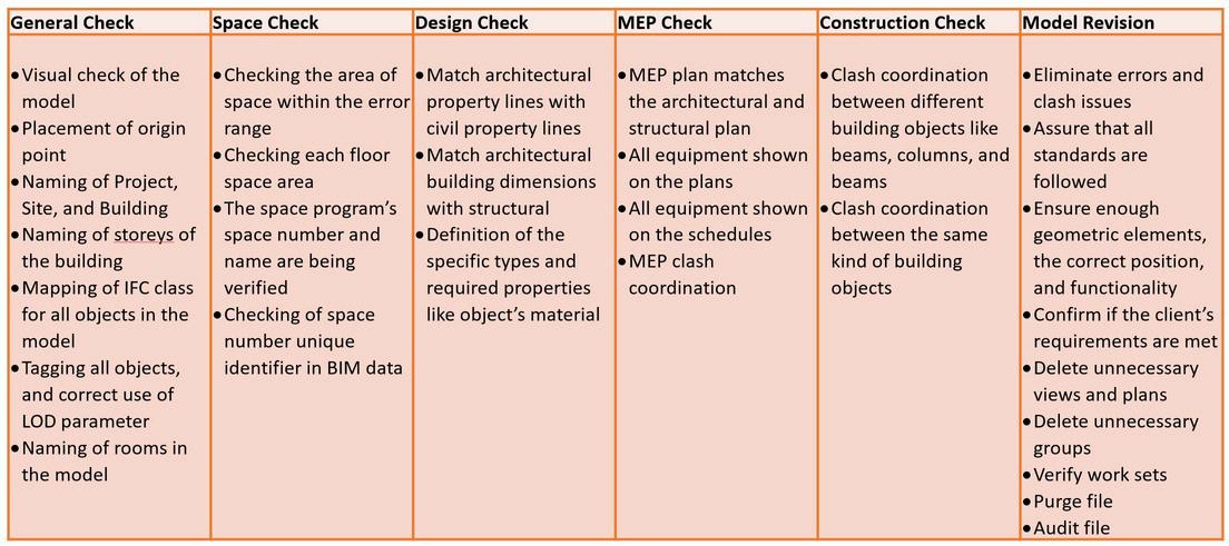
After each BIM modeling step, Quality Assurance (QA) is conducted for every system to detect and rectify errors. BIM Quality Assurance/Quality Control involves examining the BIM model to ensure compliance with various BIM standards (TEJJY, no date).
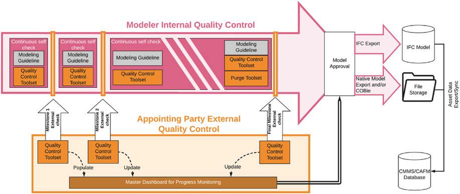
Quality control occurs at various project milestones, both internally and externally (as depicted in the diagram). Internally, the task team conducts self-checks and peer reviews, while externally, quality checks are carried out by appointed parties at different steps.
Assessing information quality involves an Information Delivery Manual (IDM). Utilising IFC schema or IDMs enables partial automation through rule-based checks (British Standards, 2021). Quality control software like Solibri Model Checker (SMC) conducts precise clash checks on BIMs, assessing various aspects including space, accessibility, structure, and compliance with regulations, based on user-defined rules (Choi et al., 2020, p.5). Moreover, there exist techniques for assessing quality tailored to specific objectives, such as adherence to building permission codes, safety standards, evacuation protocols, cost considerations, energy efficiency, and more (Choi et al., 2020, p.6).
1
T R O C U C T I O N
Figure 2:Overview of the workflow for preparing FM-BIM, outlining the checks conducted at milestones (Leygonie et al , 2022, p 9)
2
Figure 1:Checklist of Quality Control (TEJJY, no date)
I N T R O C U C T I O N
D. 4D SIMULATION
BIM dimensions have developed from the traditional distinction between two and three-dimensional geometry modeling. This progression has moved from manual drafting to 2D CAD systems, and now to advanced 3D modeling software. (Hamil, 2021)
Enhancing these models allows project teams to grasp the specific information they aim to represent. 4D generally refers to integrating scheduling data to simulate construction sequences, while 5D involves incorporating financial costs and 6D is about facility management. (Hamil, 2021)
The use of 3D visualization for coordination has become quite common in the construction industry. Although 3D models demonstrate the view of the end of the project, it is the 4D simulation which shows the process of it by adding the element of time.
Synchro is a software platform widely used in the construction industry for 4D construction modeling and project management. It integrates the planning, scheduling, and management of construction projects with 3D BIM (Building Information Modeling), allowing project managers and teams to visualize construction processes over time.
Synchro allows users to link their project schedules with 3D models, creating a 4D visualization where the fourth dimension is time. This enables construction sequences to be planned and visualized in realtime, enhancing understanding and communication across the project team (4D construction simulation explained, no date).

1
3
Figure 3: Synchro Interface Soucre Author
C A S E S T U D I E S
A. CASE STUDY N1
New Automated BIM Object Classification Method to Support BIM Interoperability
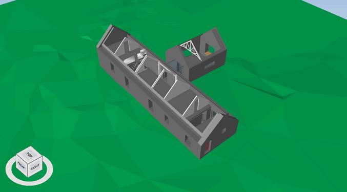
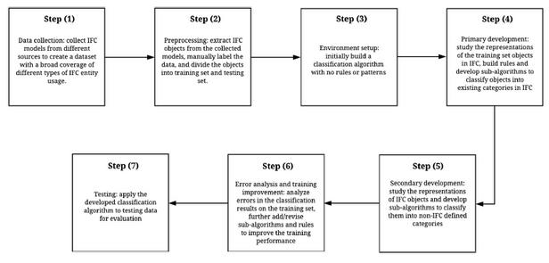
The case study focuses on a new automated BIM object classification method designed to enhance BIM interoperability, specifically utilising Industry Foundation Classes (IFC). This method was developed to address issues stemming from the misuse of IFC entities during BIM creation, which can lead to significant inaccuracies in downstream applications like automation of BIM-supported tasks. The misclassification of objects often results in incorrect semantic information, which is crucial for accurate data transfer between different BIM software.
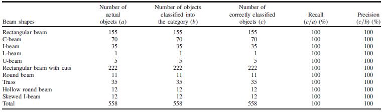
The method explained in the case study introduced is iterative and data-driven, relying on pattern matching rules based on the geometric features of AEC (Architecture, Engineering, Construction) objects. This method aims to automatically classify BIM objects into predefined categories by analysing their geometric information. Experimentation and Results: The approach was tested using IFC models from various sources, with a total of 1,891 AEC objects analysed. The classification algorithm, based on training data, achieved high accuracy, specifically 84.45% recall and 85.20% precision for common building elements, and 100% for both metrics in detailed beam categories. The study highlights that interoperability challenges often arise from the need to manually convert or adjust data when transferring between different BIM software. The proposed method helps reduce these challenges by ensuring that objects are classified correctly according to their geometric characteristics, thus supporting more accurate data exchanges.
2
Figure: 7-step method for automated IFC-based BIM object classification
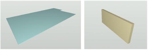
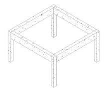
Figure 5: Extracted building elements from the duplex apartment model: (a) a slab; and (b) a wall
Figure 4: Visualization of a duplex apartment model
4
Figure 6: Beams classification results of training data
A S E
On BIM Interoperability via the IFC Standard: An Assessment from the Structural Engineering and Design Viewpoint
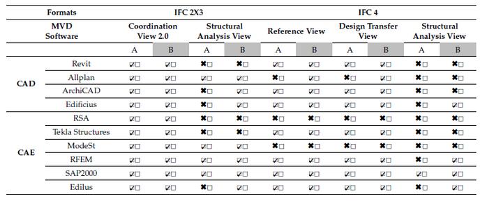
This study focuses on the challenges and advancements in interoperability between various Computer-Aided Design (CAD) with themselves and with Computer-Aided Engineering (CAE) software, particularly through the use of the Industry Foundation Classes (IFC) standard. This standard is crucial for effective data exchange in the Architecture, Engineering, and Construction (AEC) industry.
The interoperability between Revit and ArchiCAD, as explored in the document, primarily revolves around the use of the Industry Foundation Classes (IFC) standard. This standard facilitates the exchange of architectural, engineering, and construction data between different software environments, including Revit and ArchiCAD.
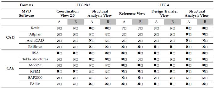
As for the data exchange mechanism, Revit and ArchiCAD often utilize a Neutral Link via the IFC standard, which serves as an independent exchange format, aiming to preserve the integrity and usability of data across different software platforms. Despite the theoretical framework provided by IFC for effective interoperability, practical challenges persist. For instance, When data is transferred from Revit to ArchiCAD or vice versa, geometric details may not always align due to different interpretations of data by each software’s internal mechanisms. Parametric details and specific element attributes can also be lost or misrepresented in the transfer process. This can result in additional time spent correcting or redefining elements within the receiving software.
Furthermore, based on a series of benchmark tests where models were exchanged between Revit and ArchiCAD using IFC, there were noticeable inconsistencies in how data was handled by each software, particularly with complex or custom elements. Both Revit and ArchiCAD have mechanisms to handle IFC data, but the effectiveness can vary based on the complexity of the models and the specific versions of the software and IFC standard being used.

2 B. CASE STUDY N2
C
S T U D I E S
Figure 8: Supported IFC import format in CAD/CAE software
Figure 9: Supported IFC export format in CAD/CAE software
5
Figure 10: Visualization of exported IFC in Revit, Archicad and Allplan
MODELING CHECKING 4D SIMULATION


The methodology employed investigate interoperability through the use of IFC along three phases: Modeling, checking, and 4D simulation. The modeling phase involve the use of two modeling BIM tools -Revit, and Archicad-, the same building will be modeled in each software, then imported in the second software to check data iteration, and lost. For example, the model created in Revit will be imported in Archicad, after finalisation and vice-versa. A comparative analysis will be then conducted. The checking phase consist of importing these models into Solibri, and classification check. The 4D simulation phase aim to provide a digital representation of the project stages that will be delivered in a hypothetic Digital Twin.
D O L O G Y 3
M E T H O
IFC - DATA EXCHANGE IFC 6
Figure 11: BIM platform workflow. Source: Author
A. PROJECT
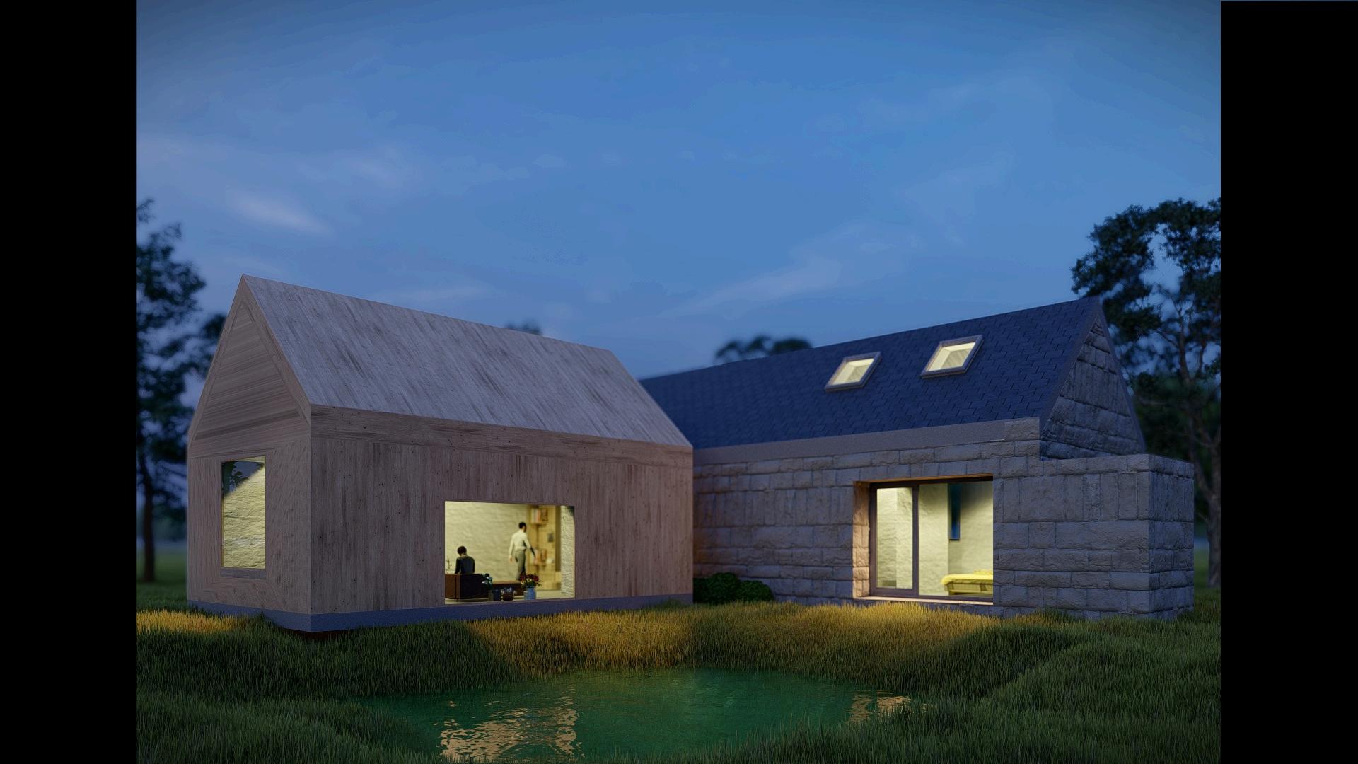
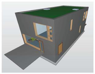
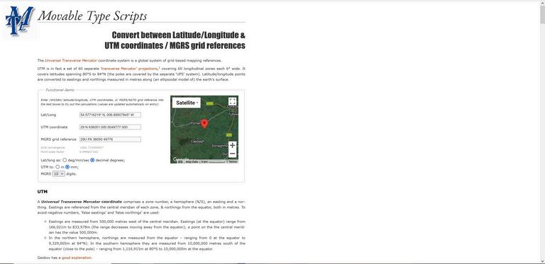
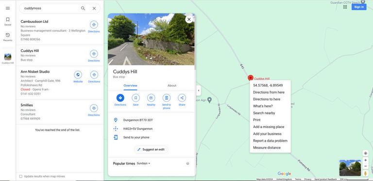
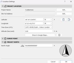
Project Name: Cuddymoss
Location: North Ayrshire, Scotland
Area: 170sqm
Architect: Ann Nisbet Studio
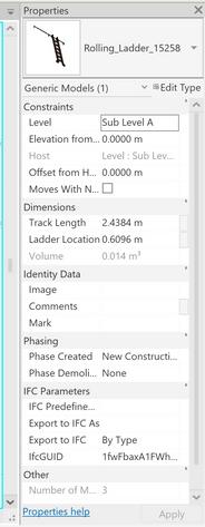
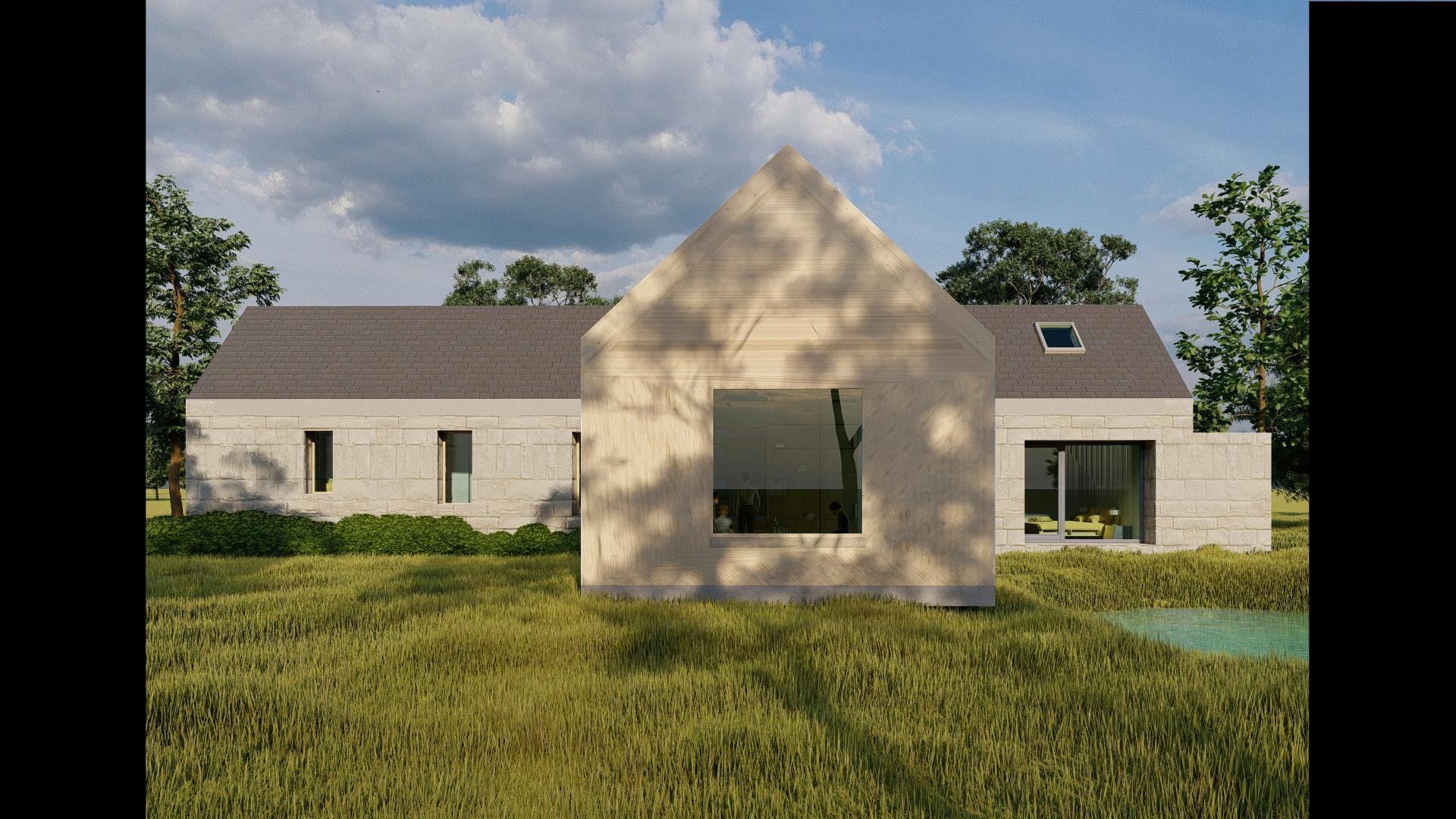
"Cuddymoss," dubbed the "House for a Bird Watcher," is nestled within a stone and brick ruin in Ayrshire, earning eight awards, including recognition in the "RIBA House of the Year Longlist 2023" and the "2023 RIAS Award " The design focused on a "building within a ruin" concept, preserving minimal original elements while inserting a timber frame within the ruins for deep window reveals A new building was also connected via a glass corridor (Ann Nisbet Studio, no date).
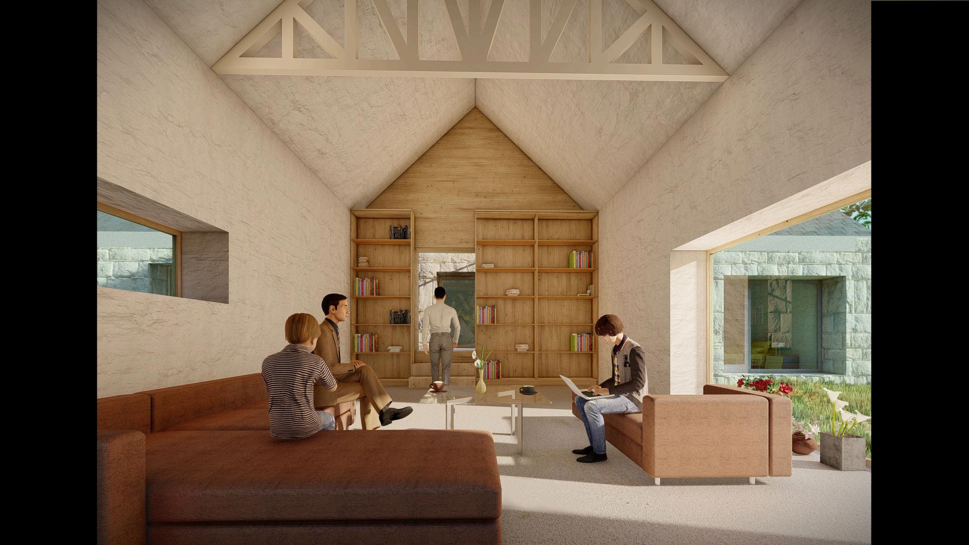
Within the renovated ruin, there is a spacious double-height living area, along with a kitchen and dining space Bedrooms are situated at either end of this area Adjacent to the ruin, the second building accommodates a separate living room (Crook, 2023)


The process of modeling, analyzing, and simulating this project can be divided into five steps according to the RIBA plan of work:
Stage 0, Strategic Definition: Reviewing the assignment criteria, deadline, and defining the project
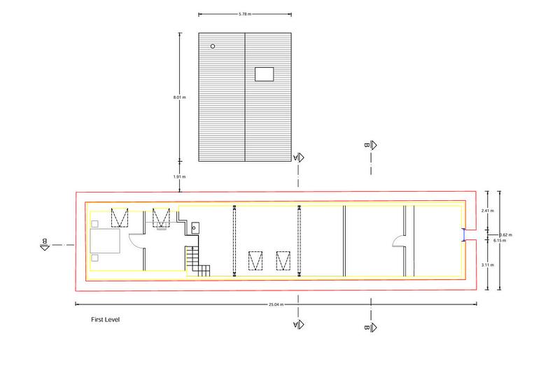
Stage 1, Preparation and Briefing: Gathering information and details of the project, including plans, elevations, sections, construction details, site topography, and coordinate points.
Stage 2, Concept Design: Providing CAD drawings based on available documents, modeling the topography of the site, as well as the basic building elements with an LOD of 200 in Revit and ArchiCAD
Stage 3, Spatial Coordination: Using Solibri to check the models and then modifying them to provide the proper level of information. According to ISO 19650
Part 2, clause NA.4.4, the classification for information containers is in accordance with Uniclass 2015. The alphanumeric information is also structured in accordance with COBie, and the information exchange takes place with IFC (open data format)
Stage 4, Technical Design: Adding construction details to the models according to the requirements of 4D simulation in Synchro and running the simulation in Synchro.


4
F R A M E W O R K
7
Figure 12: House picture (Ann Nisbet Studio, no date)
B. COLLABORATION
I. COMMON DATA ENVIRONMENT (CDE)
Trimble Connect is a cloud-based platform designed to enhance collaboration in construction projects by integrating people, data, and workflows. This CDE is particularly beneficial in the context of Building Information Modeling (BIM) due to its robust features that foster integration, communication, and efficiency. It was chosen to be used in our project as it supports IFC files, its integration with BIM Software and real-Time Access and Updates. Trimble Connect integrates smoothly with major BIM software like Revit, Tekla Structures and Archicad and creates more efficient workflow, as data can be directly imported or exported from these platforms. It also enables project stakeholders, including architects, engineers, contractors, and owners, to collaborate seamlessly. Everyone can access, review, and update BIM models and associated data in real-time, ensuring all parties are always on the same page.

II. TASKS ALLOCATION AND RESPONSIBILITY ASSIGNMENT
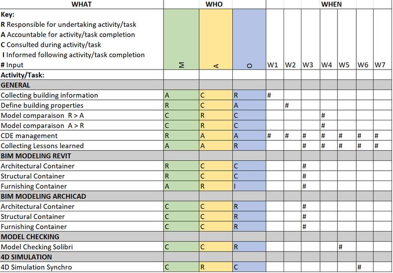
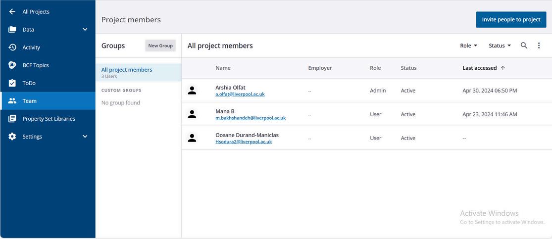
Figure:14: Detailed responsibility matrix project. Source: Author
According to the ISO 19650-2, it is crucial to carefully allocate tasks and responsibilities at the detailed responsibility matrix level. ISO 19650-2, clause 5.4.2, mentions the following components to be identified by the detailed responsibility matrix:
WHAT information is to be produced
WHEN the information is to be exchanged with whom (in this case the whom are the other members of the delivery team–lead appointed party–).
WHO (which task team) is responsible for its production.
The detailed responsibility matrix serves as the link between the high-level responsibility matrix and the delivery plans (ISO 19650-2:2018).
F R A M E W O R K 4
Figure 13:: Project Members in Trimble Connect. Source: Author
.
8
B. COLLABORATION
III. COLLABORATION PROCESS THROUGHOUT THE PROCESS: UNICLASS, CDE USE,
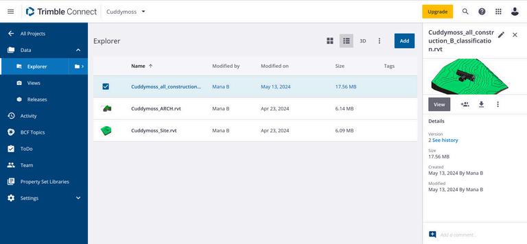
At each stage, there was a work-in-progress state wherein the model's quality was ultimately checked by the modeler. Subsequently, it was shared with a second member to conduct a review and quality check (peer review). Finally, the model was checked by a third member and shared in the CDE. In the event of a failed quality check, the model was returned to the first step of modeling to repeat the steps. After each step was uploaded into the CDE (Trimble), other members downloaded the file via the online platform. In case of any problems or mistakes, the model was marked up in Trimble. Another application used for collaboration was Microsoft Teams, through which online meetings were scheduled and additional documents and resources were shared.
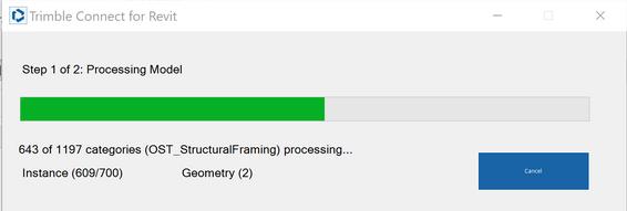
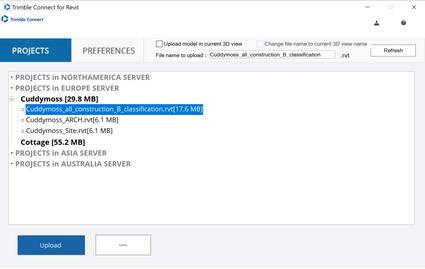
15: File Uploader, Trimble Connect plugin for Revit Source: Author
https://uniclass.thenbs.com/
C. COLLECTING LESSONS LEARNED STRATEGY
Model creation Model comparaison - IFC Model checking Model 4D simulation Lessons captured Lessons learned
Along the stages of the project, feedback has to be collected to record lessons learned. To match BIM standard, we are going to adopt the ISO 19650 strategy (Clause 5.8.2: Capture lessons learned for future projects). Within the delivery team, the appointing party shall capture lessons learned during the project and record them in a suitable knowledge store, to be called upon by future projects. It is recommended that lessons learned be captured throughout the entire project.
CLASSIFICATION:
UNICLASS
F R A M E W O R K 4
Figure:
Figure 16: Model overview in Trimble Connect Source: Author Download
9
Figure17: Classification naming according to UNICLASS
A. PRE-MODELING
Tasks:
Define layout, levels, site topography, coordinate point and dimensions in AutoCAD interpreted from different resources found on the project.
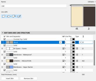
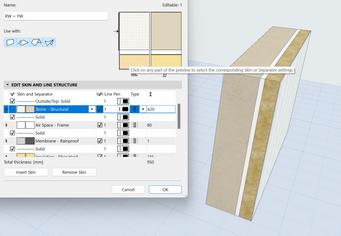
Creation of a colour key, and a naming classification to defines different walls type.
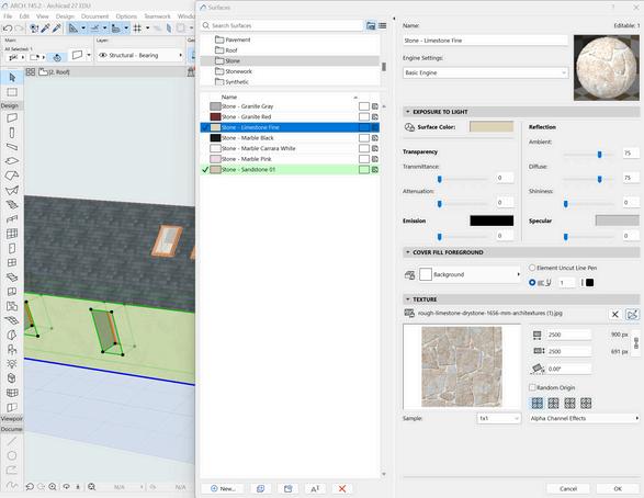
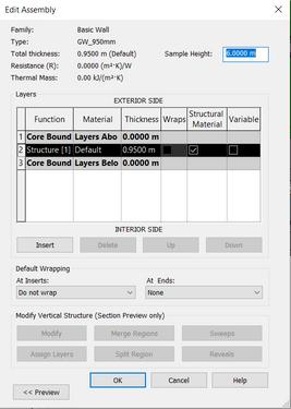
Define materials structure of the different wall types in Archicad.
Final review and share for 3D modeling. **Shared and reviewed with consu tation of the team members
3D BIM Modeling
1 2 3 4 1 2 3 3 2 1 1 M O D E L C R E A T I O N 5
** **
1
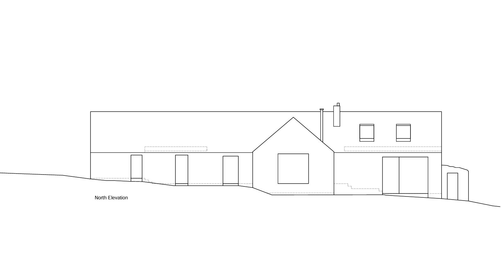
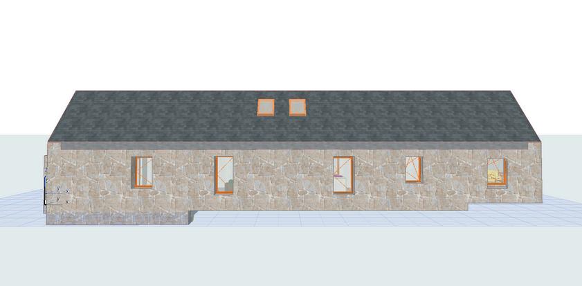
Figure: 24: North Elevation AutoCAD
Source: Author
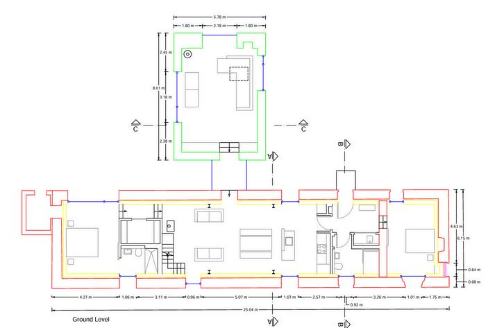
Figure: 23: Ground Floor AutoCAD Source: Author
Figure 22:: First Floor AutoCAD Source: Author
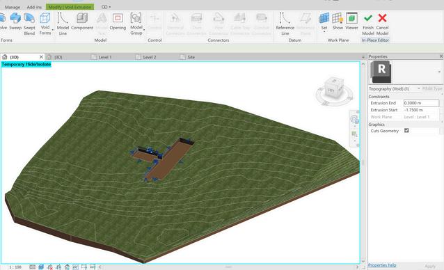
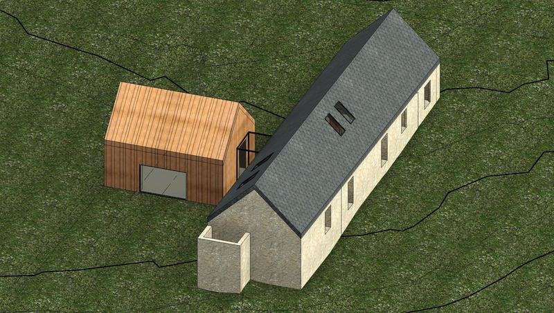
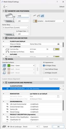
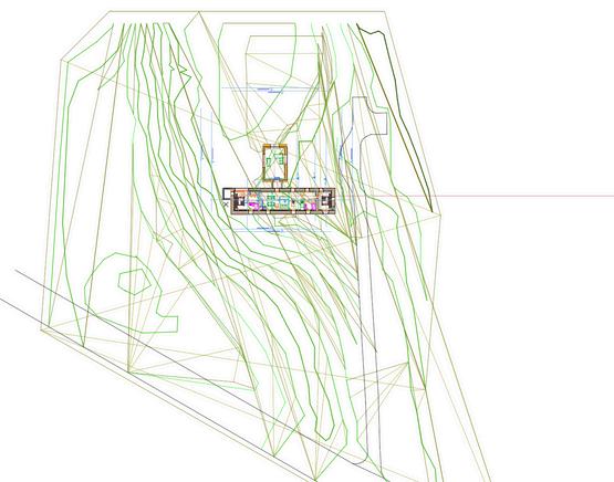
Figure 19: Topography process Source: Author
Figure 20:: Component materials green wall definition ArchiCAD Source: Author
10
Figure 21:: Component materials red wall definition ArchiCAD Source: Author

M
C R E A T I O N 5 11
O D E L
Figure: 18 Model Floor plans Revit & Archicad Source: Author
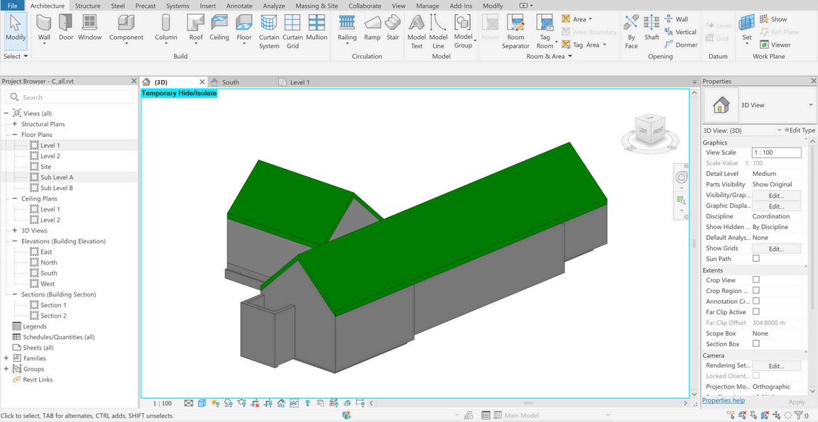
A. REVIT MODEL
Setting levels
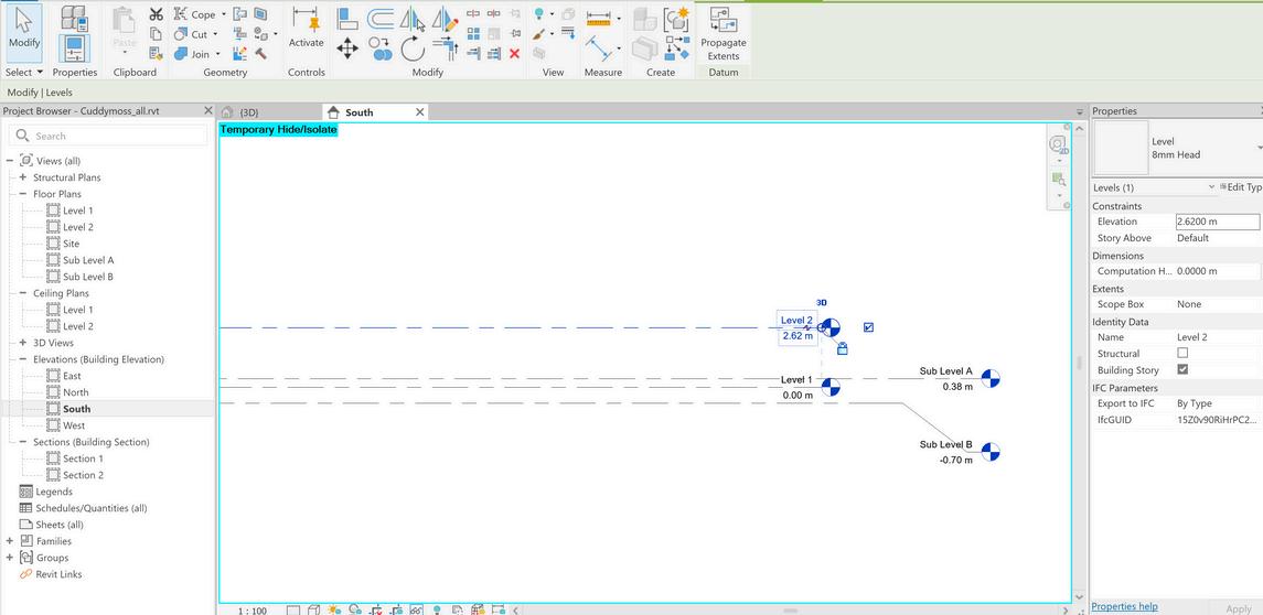
Setting location
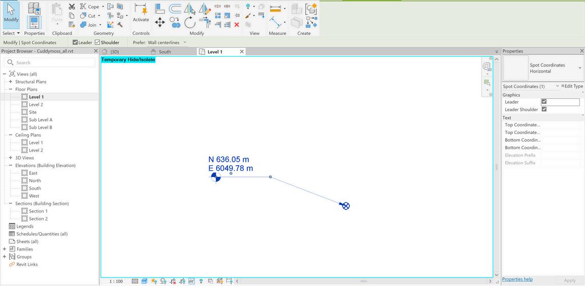
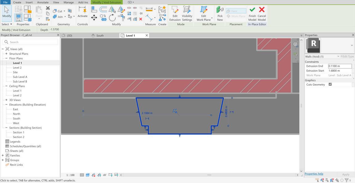
Creating slabs and topography
Creating walls

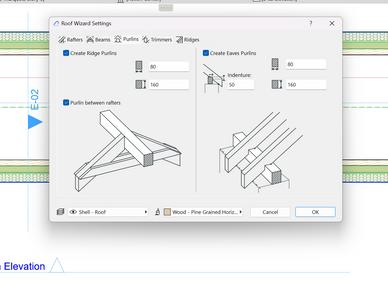
Creating roof
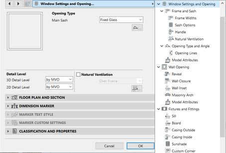
Creating windows second wall
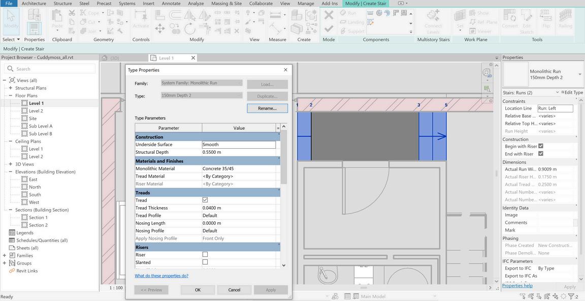
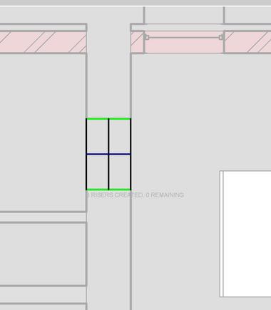
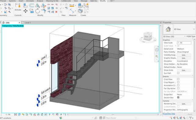
Creating stairs
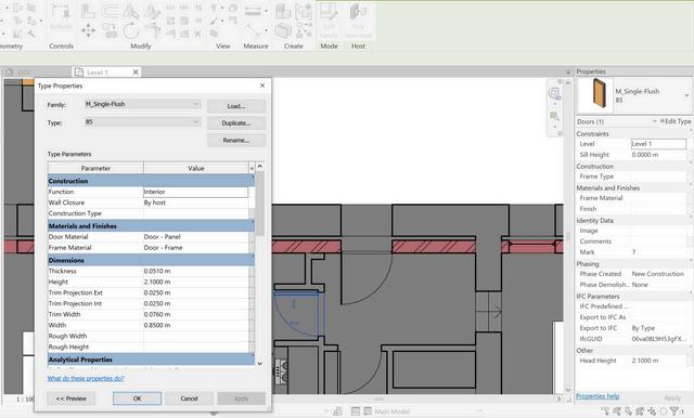
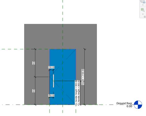
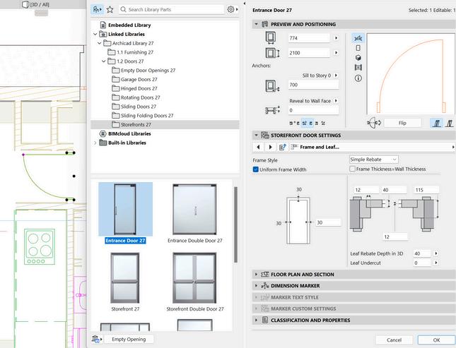
Creating doors
Creating opening heritage wall
1 2 3 4 5 6 7 8 9 M
L C R E A T I O N 5
O D E
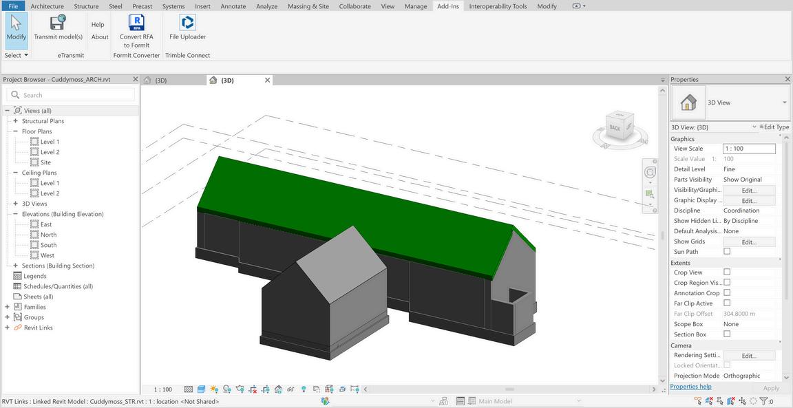
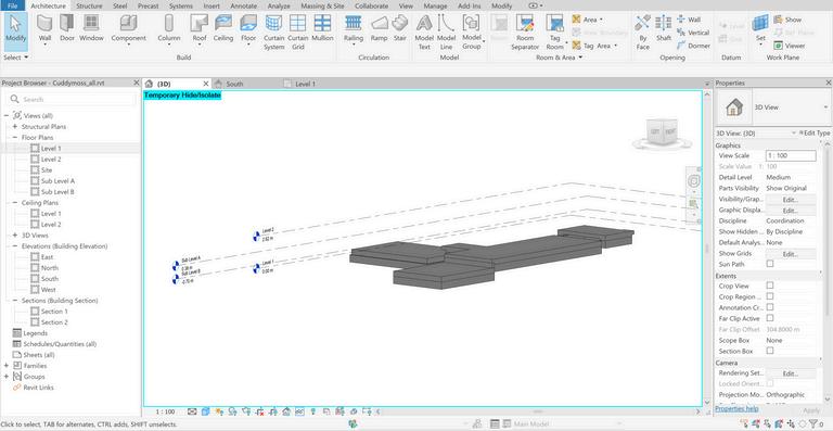
25: modeling process in Revit Source: Author 12
Figure
A. REVIT MODEL


10 11 12 13 14 M O D E L C R E A T I O N 5
Creating stairs
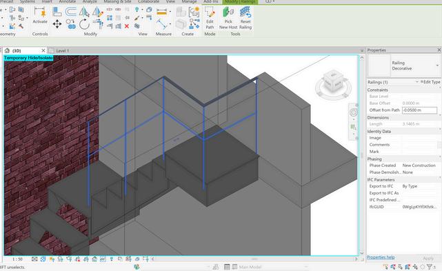
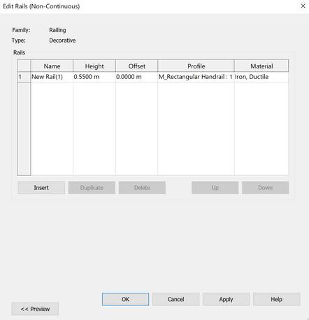
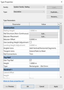
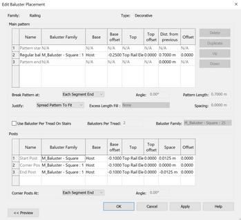
Creating Railing of the stair
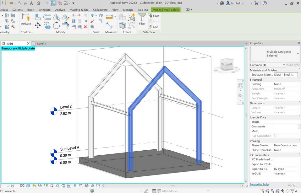
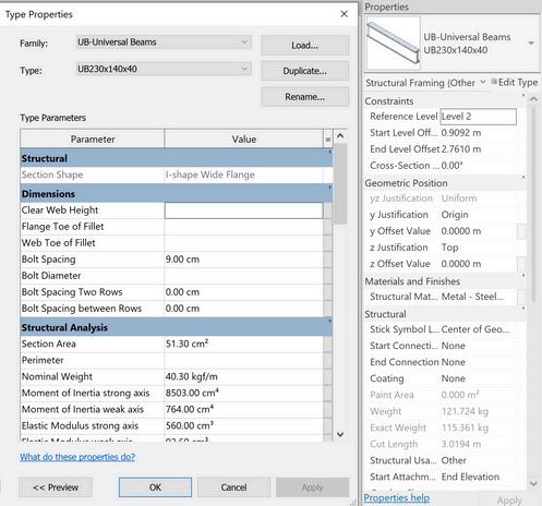
Creating metal frame
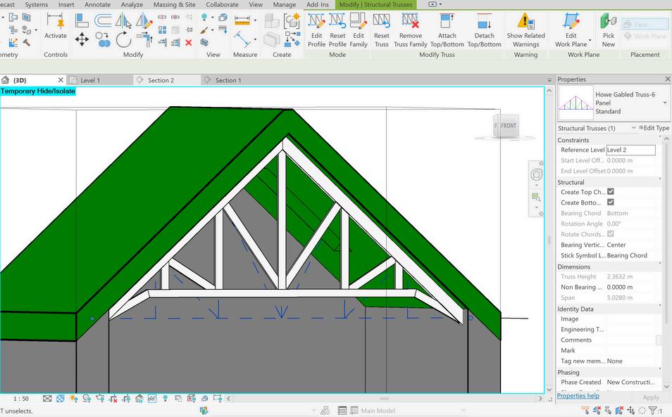
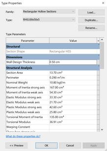
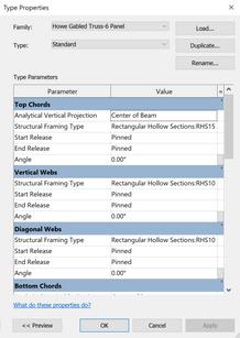
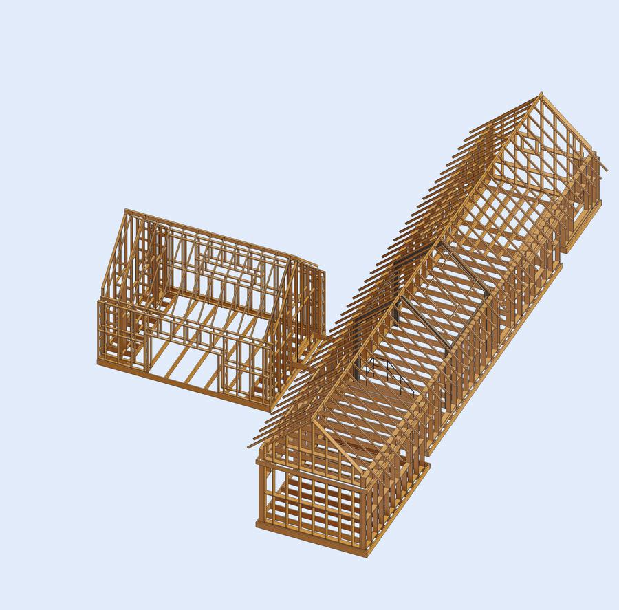
Creating truss
Final Model
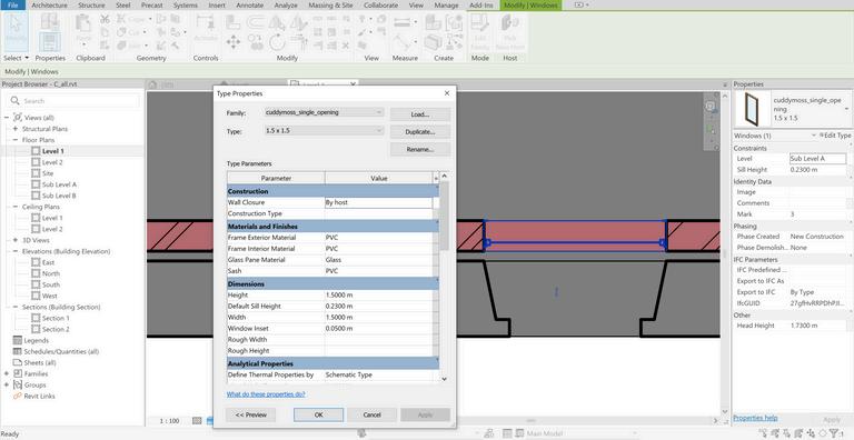
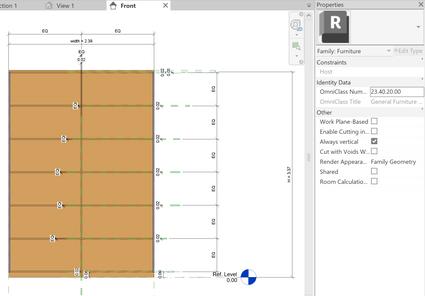
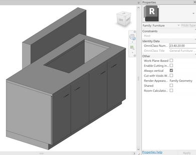
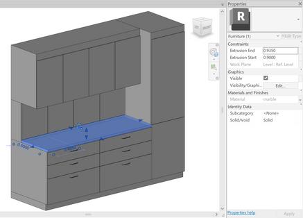
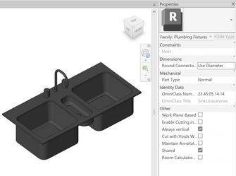
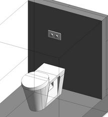
Creating furniture and adding bespoke furnitures
Adding construction details
bis: modeling process in Revi Source: Author 13
Figure25
B. ARCHICAD MODEL
Setting levels
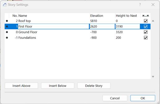
Setting Location and setting topography
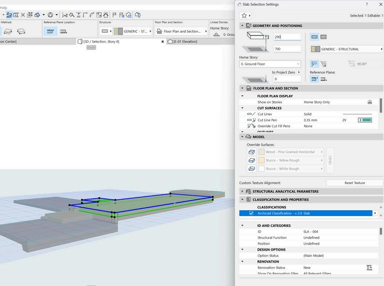
Creating slabs
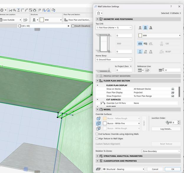
Creating walls
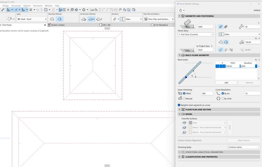
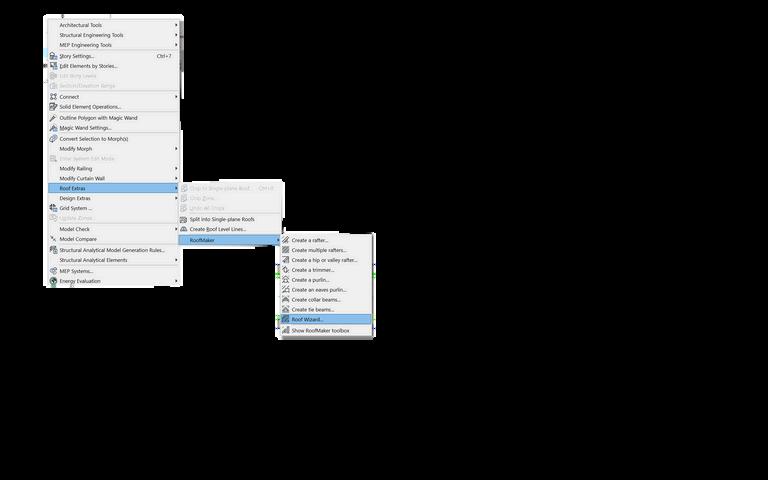
Creating roof
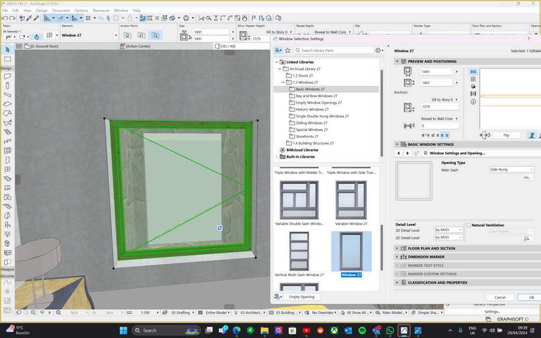
Creating windows second wall
Creating opening heritage wall
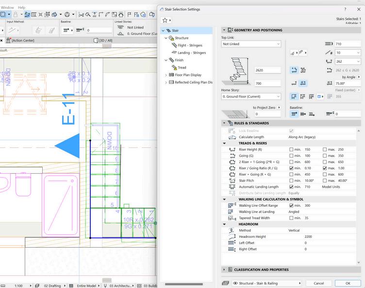
Creating stairs
Creating doors
1 2 3 4 6 7 9 M O D E L C R E A T I O N 5
14
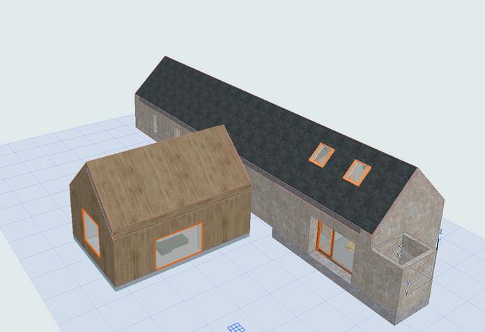
Figure 26: modeling process in Archicad Source: Author
B. ARCHICAD MODEL
Creating stairs
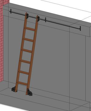
Creating shapes and classify object
Adding furniture and bespoke furnitures
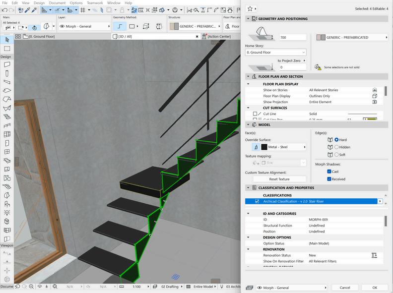
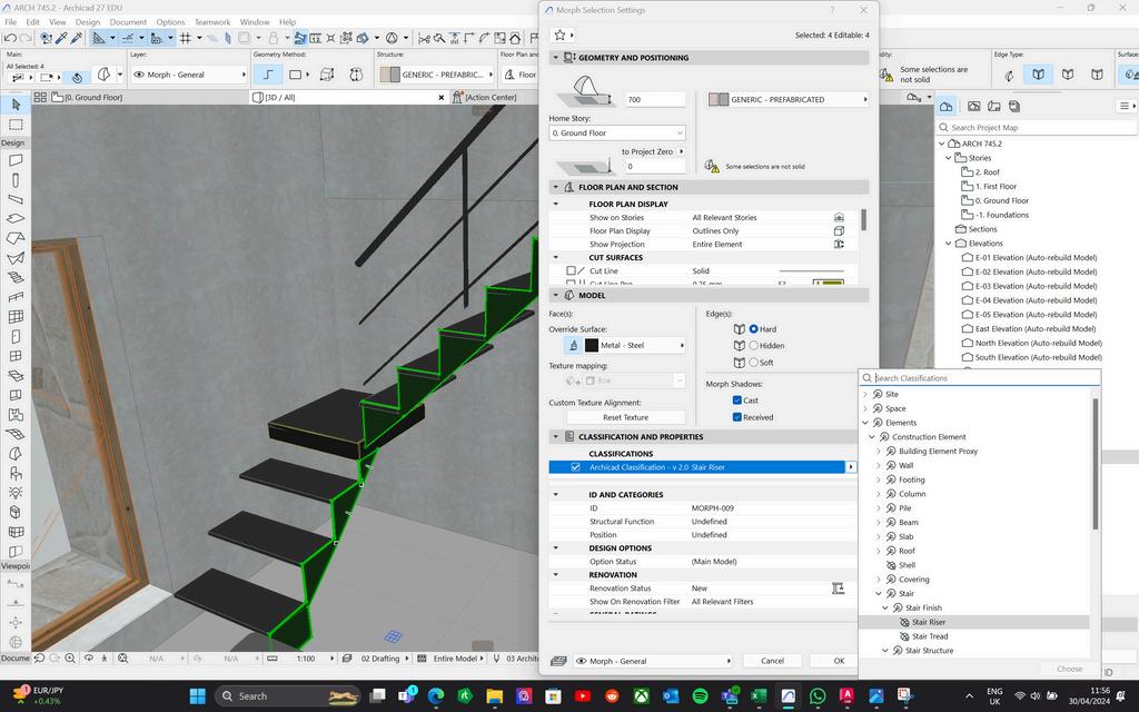
Creating metal structure
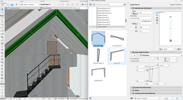
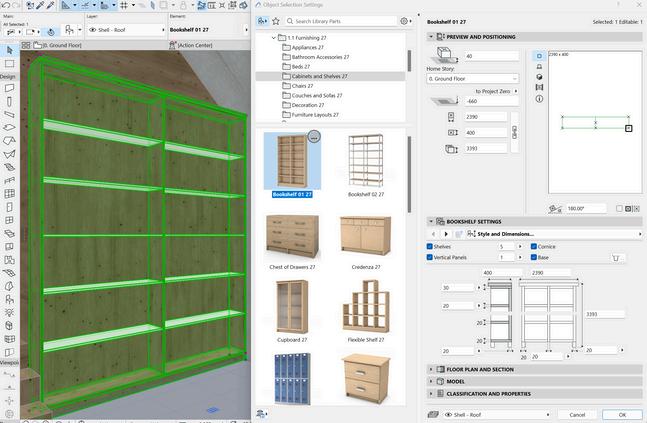
Changing material visualisation
Creating roof structure

10 1
L C R E A T I O N 5
M O D E
Final Model
15
Figure 26 bis: modeling process in Archicad Source: Author
A. GEOMETRY
M O D E L C O M P A R A I S O N
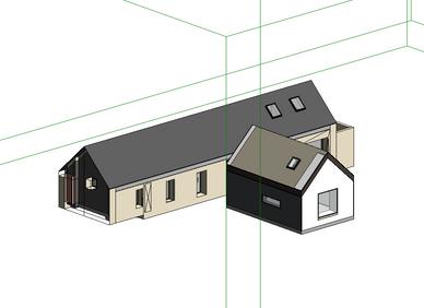
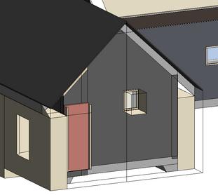
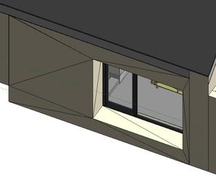
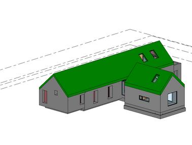
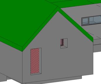
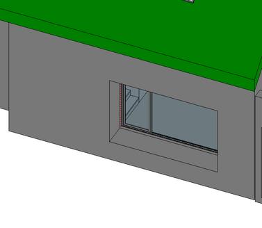
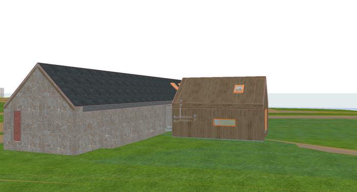
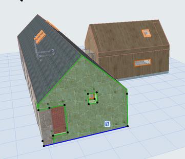
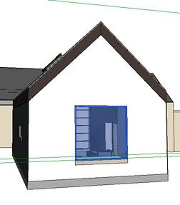
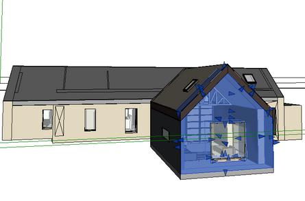
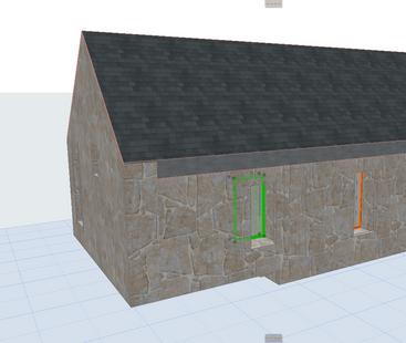
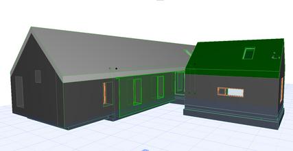
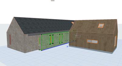
The geometries in the Revit model and the imported IFC from Archicad to Revit are quite similar. One of the differences was that the model in some parts as shown in the picture had more meshes and lines. Also, an element as shown in the second picture was not shown correctly in the viewport which was because of the opening in the wall. After the opening was removed and reimported this issue was fixed.
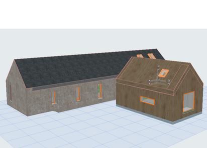
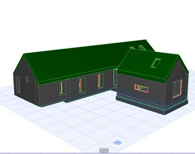
The geometries in the Archicad model and the imported IFC from Revit to Archicad were completely similar. Compared to the revit model, the results were more accurate and similar. The only differences were due to the change in the material but the geometries were similar.
6
Figure 27: Overal view of the models in Revt. Source: Author
Figure 28: Geometrical issue (visibility issue) Source: Author
Figure 29: Geometrical issue (extra meshes Source: Author)
Figure 30: Overal view of the models in Archicad. Source: Author
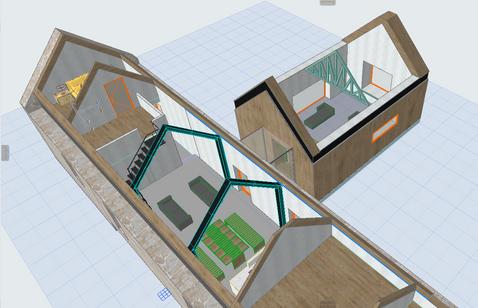
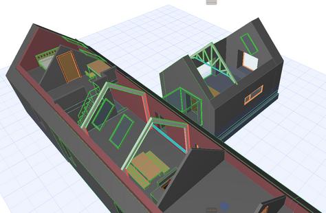
16
Figure 31: Interior view of the models in Archicad. Source: Author
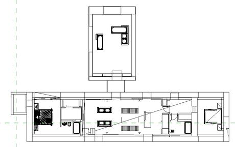
B. ATTRIBUTES/ 2D DRAWINGS
M O D E L C O M P A R A I S O N
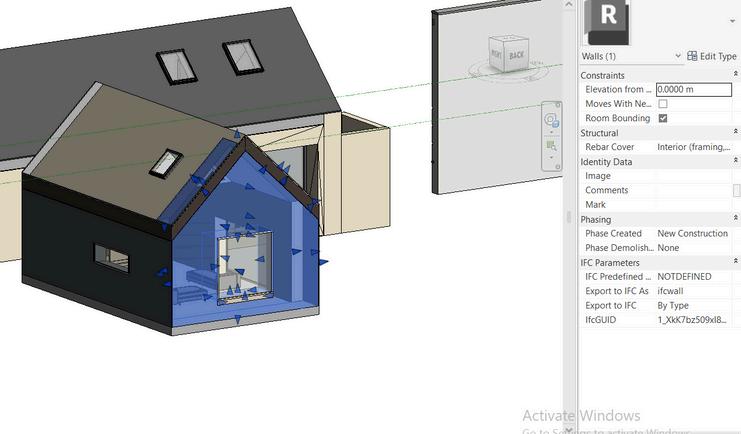
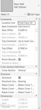
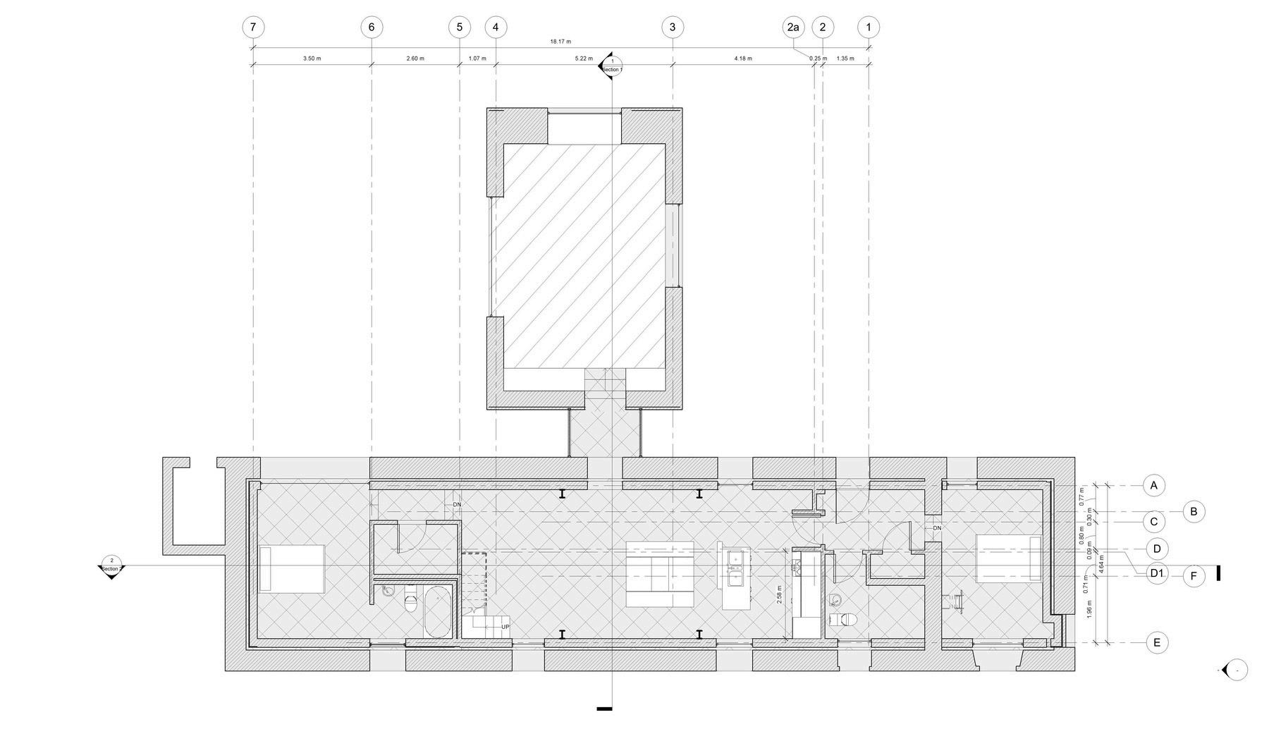
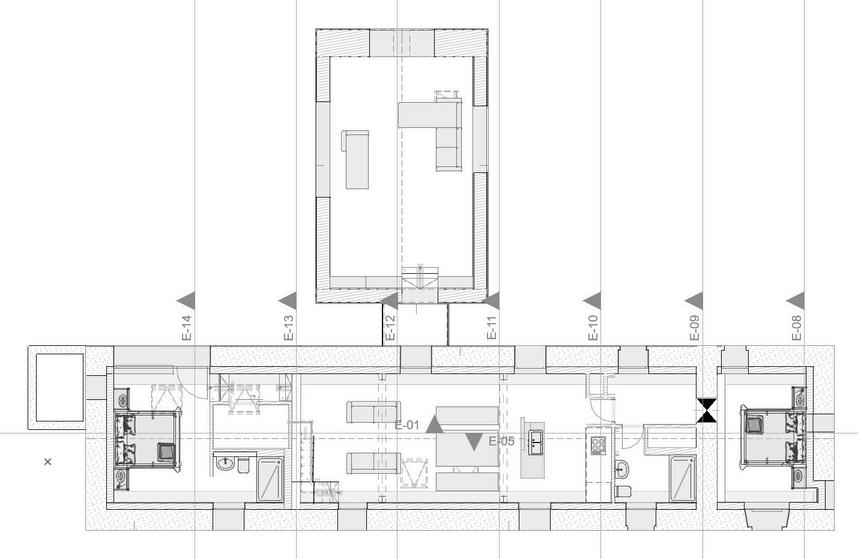
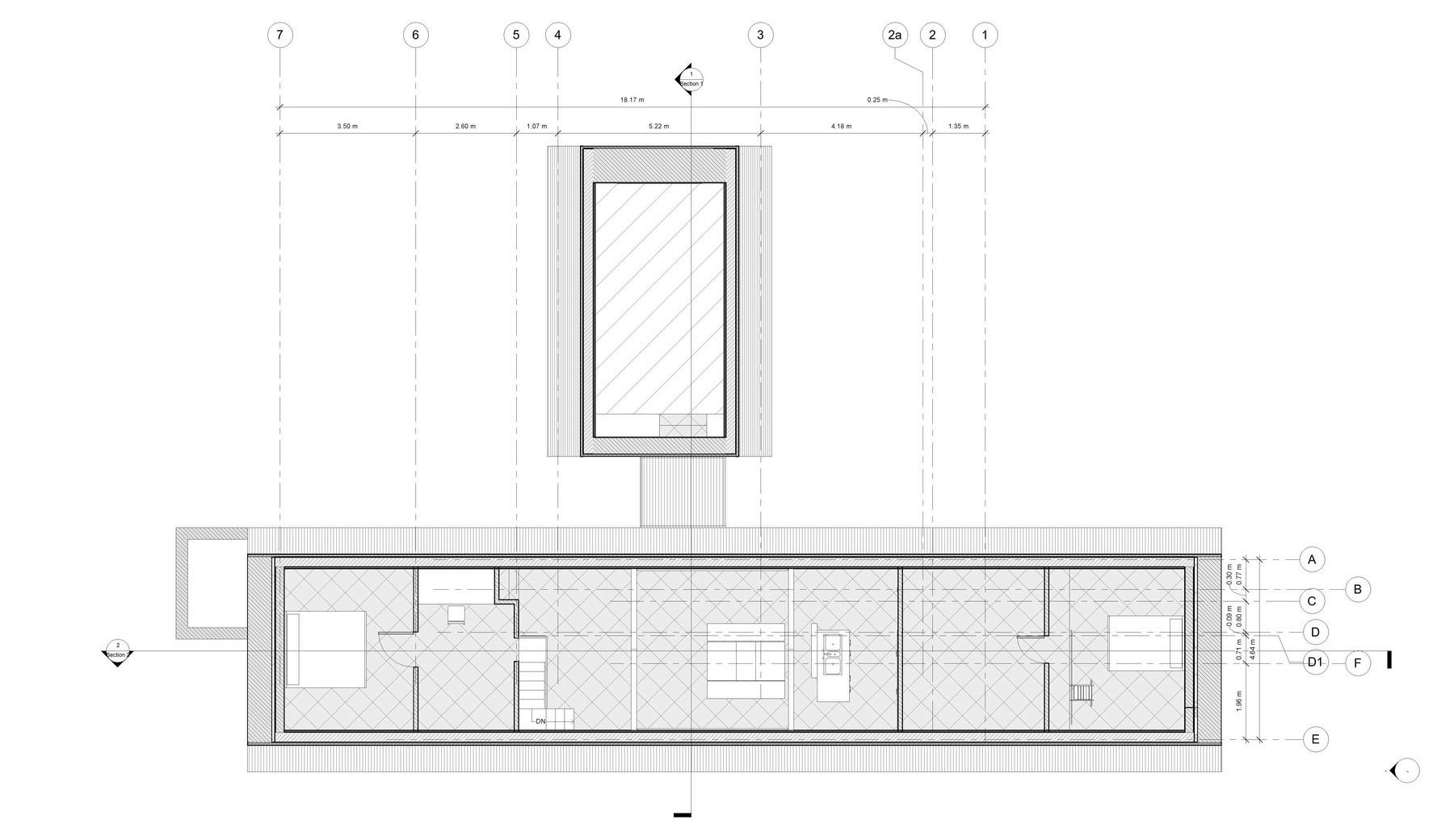
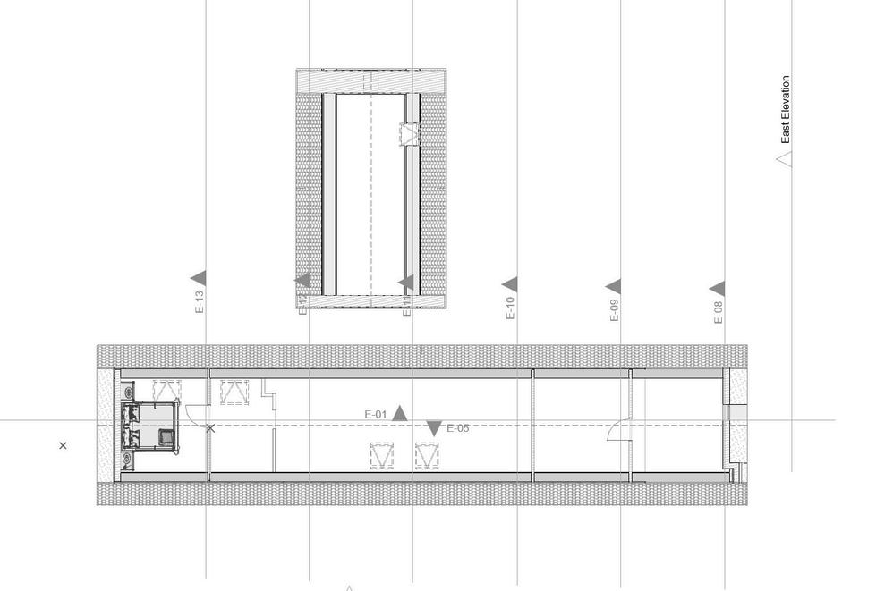
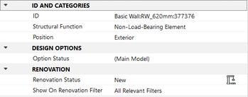
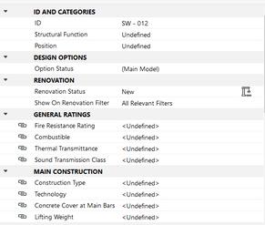
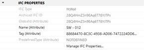
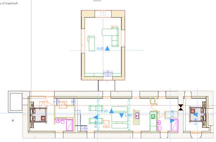
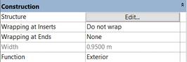
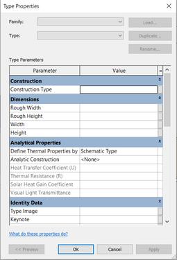
The attributes in the imported model from Archicad are very limited. Most of the parameters to define objects are different in the software so compared to the original Revit model attributes are restricted. Also, after navigating through the 2D drawings, some of the elements like the windows were not shown in the Plans. After some modifications to the levels of the imported ifc from archid and editing the view range from properties the issue was fixed to some extent. But still some of the elements were shown in the wrong levels or not shown at all.
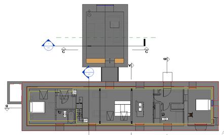
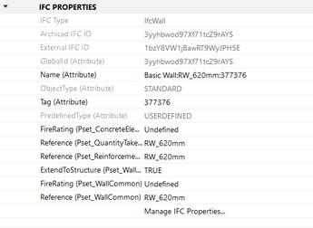
The attributes in the imported IFC from Revit had the same issue and because of the different object properties were very restricted. Unlike the AR model, the RA model didnt have any issue with the 2D drawings. At first the details werent shown, but after setting the roof layer backwards we could see all the objects in the Plans.
6
Figure:32 imported IFC wall properties Source: Author
Figure 39: Original Revit file wall properties Source: Author
Figure 37: Archicad wall properties.. Source: Author
Figure 35: imported IFC wall propertiesSource: Author
Figure: 36 Ground floor plan in imported IFCSource: Author
Figure 38: Ground floor plan in original Archicad file Source: Author
Figure 34: Ground floor plan in original Revit file Source: Author
17
Figure 33: Ground floor plan in imported IFC Source: Author
C. EDITION
M O D E L C O M P A R A I S O N
Source: Author
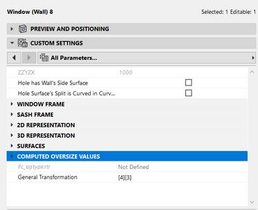
The exported IFC from Archicad to Revit does not have lots of editing options. Editing with parameters cannot be done as the categories are not identified. The only editing option is by doing it manually with the use of arrows which are shown in the first picture.


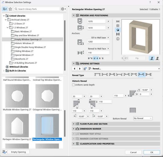
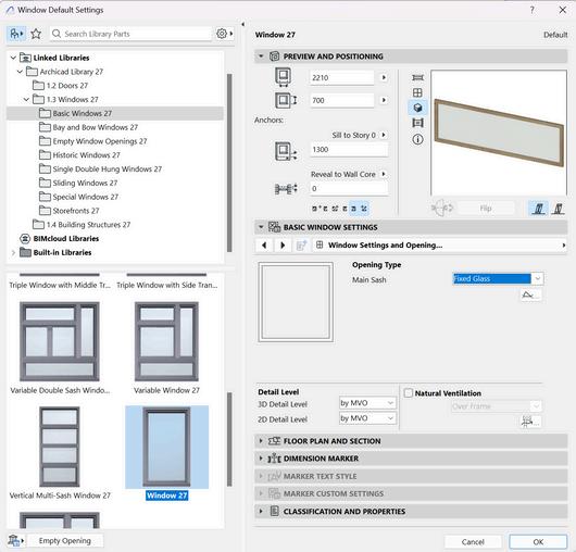
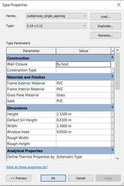
The exported IFC from Revit to Archicad allows more changes compared to the Revit one. Editing can be done with both the parameters and also manually. Although the parameters are very limited compared to the Archicad model. For instance for the windows editing with parameters can be done but the parameters are very limited compared to the archicad file as it can be seen in the photos. Also, some of the object’s types are not recognized which in this case parameters are even more limited for editing objects.
6
Figure 40: wall parameters in the imported IFC Source: Author
Figure 39: wall parameters plan in original Revit file
Figure 41: window parameters in the imported IFC. Source: Author
Figure 42: window parameters in the original Revit file. Source: Author
Figure 45: window parameters plan in original Archicad file. Source: Author
Figur 44: Object type in the imported IFC. Source: Author
Figure 43: window parameters in the inported IFC Source: Author
18
Figure 46: object type in the original Archicad file. Source: Author
O D E L
O M P A R A I S O N
D. CONCLUSION
Issues
After exporting our file with IFC 4 the geometry was gone after importing it in the software interface
Visibility of some of the complex geometries was unclear in Revit.
After importing the file, the project scale was not correct as it was too small
Solutions
The use of IFC 2*3 solved the issue
Simplification was brought to the Archicad model and the Revit model after exporting.
Model units in the source and destination software should be set and reviewed before importing the IFC file.
Table 1: Overview of issues and solution found in the model comparison phase
Based on our experiment, there were some pros and cons in the usability of IFC files. First of all, there is the possibility of interoperability between Archicad and Revit, especially for editing geometries and changing some of parameters it is very useful. On the other hand, data loss is pretty common in this process. Exporting an IFC from a BIM software like Revit to its self has a limited data loss but export and import to different BIM software significantly increases the data loss. The main reason for that is that each software has different set of properties and parameters for the objects which are not compatible with other software and even the IFC schema cant change that. Moreover, complex geometries might as well have some change in their appearance after they are imported to the BIM software. The main reason is each software has its set of rules to create the faces and geometry in its interface. The solution is to simplify the model to some extent before exporting and do the modification to the geometry after importing it.
E. LESSONS LEARNED
Information on the model such as coordinates, level and other details have to be defined at the early stages of the project, saving time on the modeling phase.
Some plugins were required in Revit, testing the availability and access to the tools could save time.
Concerning the CDE (Trimble) a pre-training might be required to fully understand interoperability tools available in Trimble.
M
6
C
19
A. MODEL PREPARATION
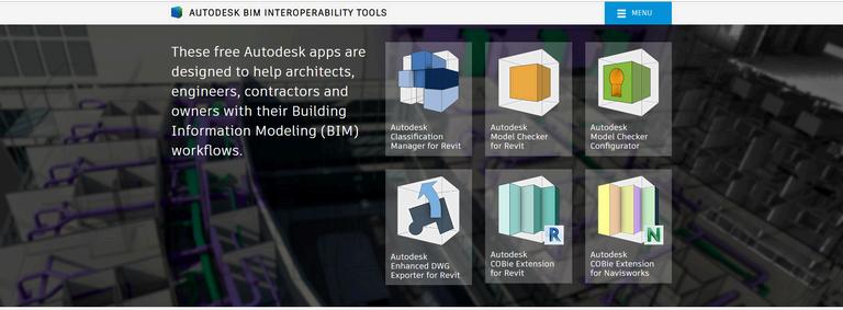
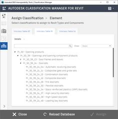
Prior to checking the model in Solibri, the classification system in Revit was assigned. Autodesk BIM Interoperability Tools are a set of free apps (e.g., classification manager, COBie extension, etc.) for Autodesk users, which facilitate the BIM workflow. In this way, assigning classification to the model elements is semi-automated.
B. IFC IMPORT
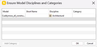
Importing IFCs into Solibri is a simple process. The software automatically extracts data from the IFC file and converts it into a 3D model within embedded data. this allows to quickly identify any potential issues or discrepancies in the model. As the first action after importing the IFC, disciplines of the model have to be identified.
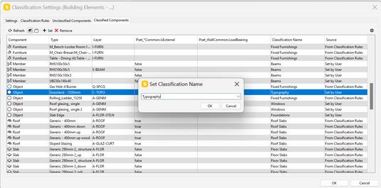
C. CLASSIFICATION
Classified unclassified component
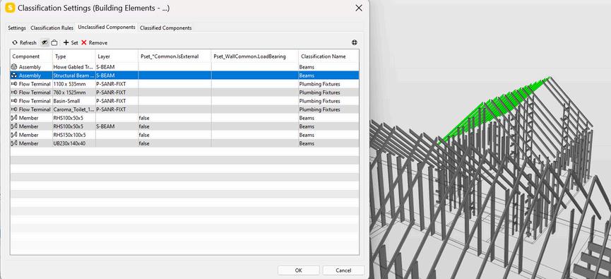
D. CHECKING
i. Visual checking
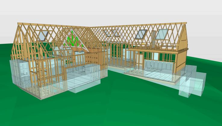
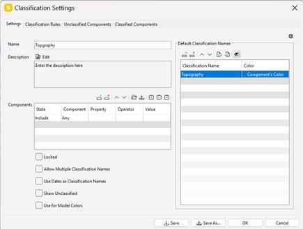
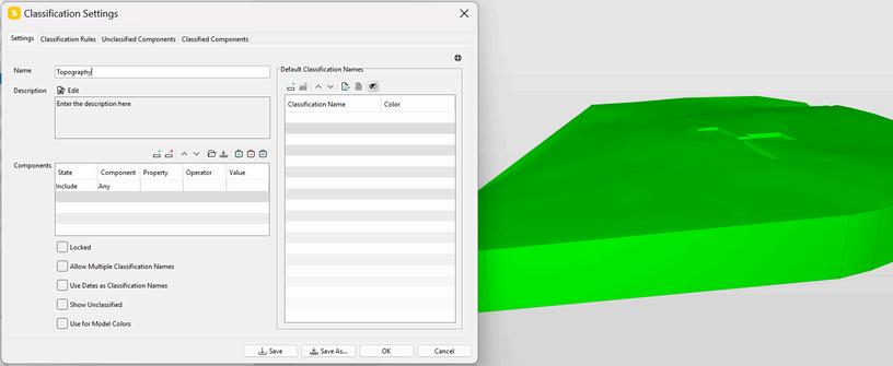
Create a classification for the Topography
1 2 M
C H E C K I N G 7
O D E L
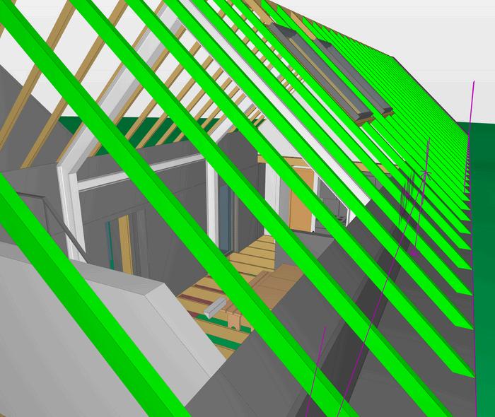
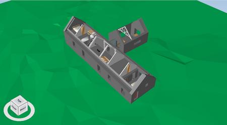
Figure 51: Timber structure model Source: Author
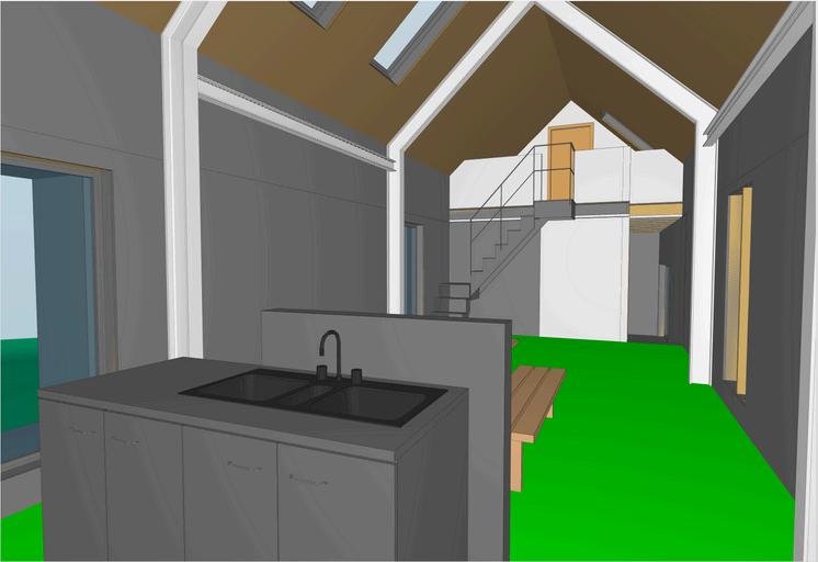
Figure 52: Interior- Living Room Source: Author
Figure 50: Creation of Topography name classification Source: Author
Figure 49: Classify non classified components. Source: Author
20
Figure 48: Picking discipline Source: Author
Figure 48: Autodesk interoperability plugins (Autodesk, no date-b)
M O D E L
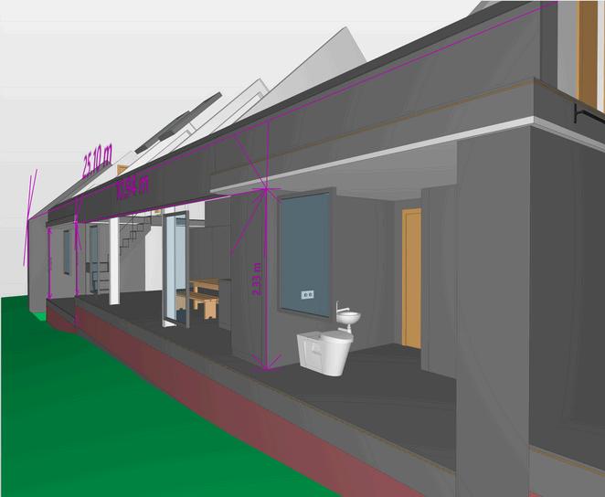
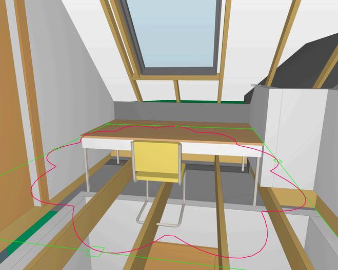
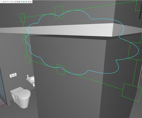
II. Dimensions & Markup
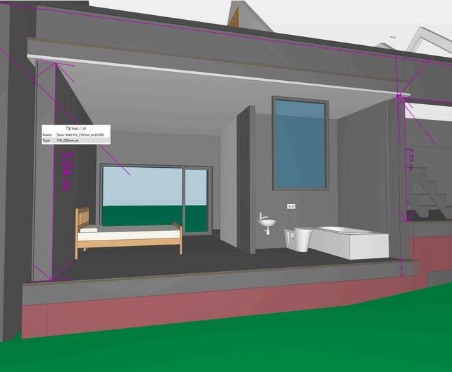
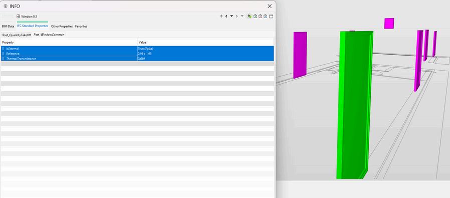
III. BIM Data
C
E C
G 7
H
K I N
Figure 53: Dimensions Level Checking 1. Source: Author
Figure 54: Dimensions Level Checking 2 Source: Author
Figure 55: Markup tool Showing a clash Source Author
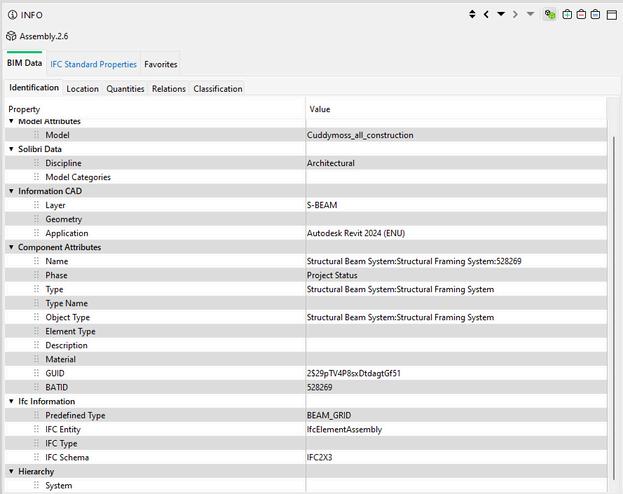
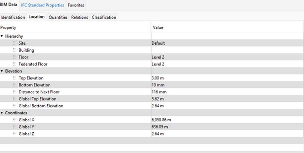
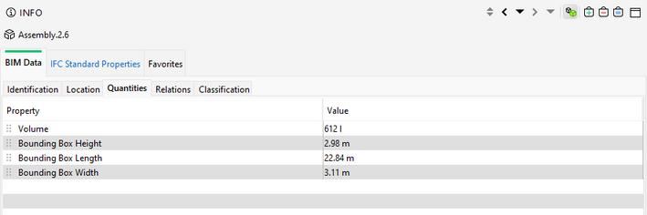
IV. IFC DATA
21
Figure 56: BIM Data checking with IFC by identification, location, and quantities. Source Author
Figure 57: IFC Data in Solibri. Source Author
M O D E L
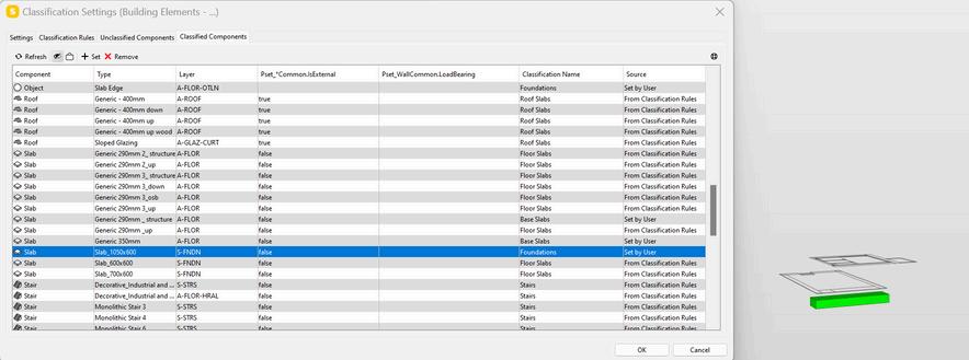
V. Checking Pre-existant classification
VI. Select Rules checking
VI. Select components
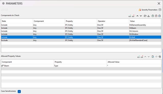
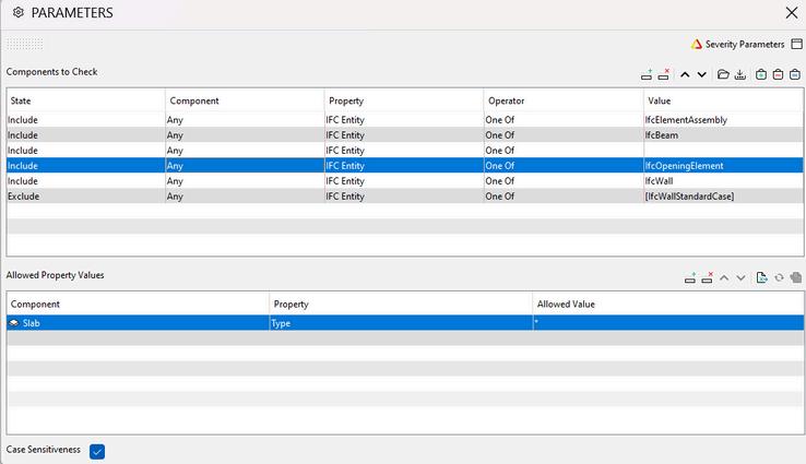
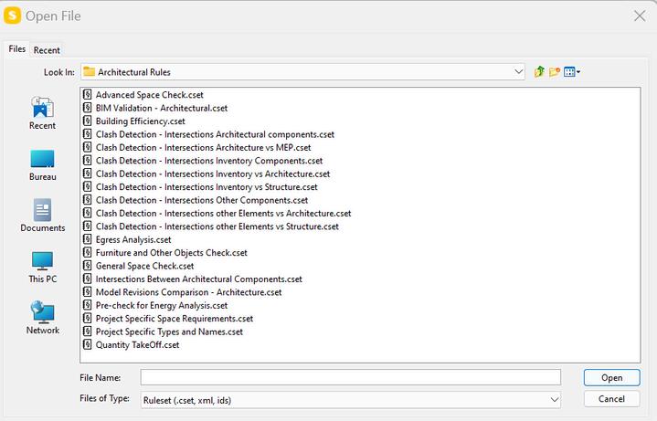
To ensure accurate information and effective coordination, a set of rulesets were created. These rulesets were aligned according to the project requirement such as coordination, naming checking, or clash avoidance.
In this portfolio several rulesets were selected, the first focus was to perform an architectural and structural check based on the classification system. This allows to identify missing design concepts among principal functions between components. As the second focus, rulesets for tolerances between structural and architectural construction, then between architectural component selected were used. This ensured checking of critical clashes during the Spatial coordination stage.
C
C K
G 7
H E
I N
Figure 58: Changing classification name from Slab to Foundation Source Author
to check
Figure 59: Selection of component to check Source:
Author
22
Figure 60: Pop-up window to select ruleset in Solibri. Source Author
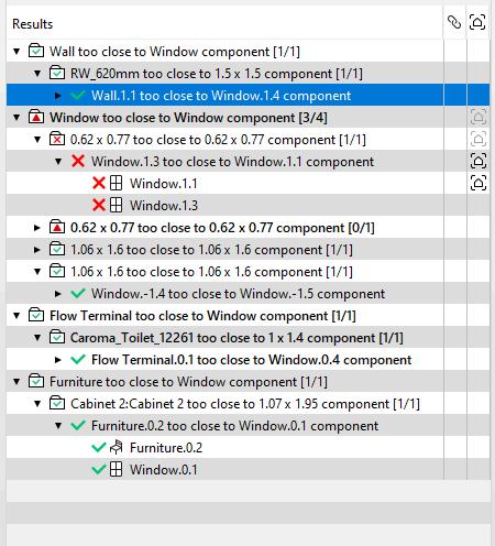
VI. Run checking a. Architectural and component check
1 Checking the clashes reported
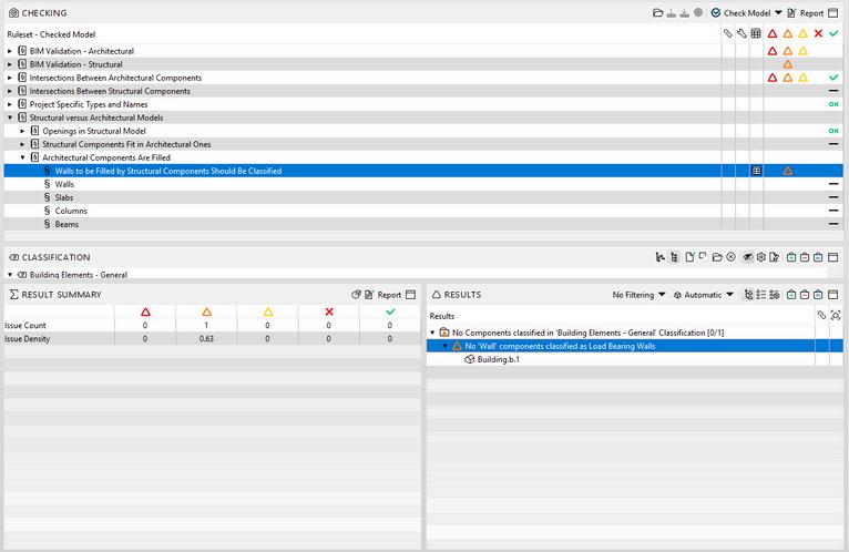
This issue could be solved in Solibri, by changing some external walls types to load bearing wall
3 Solving the issue in Solibri
2 Identifying the Issue
The classification naming checking identifies missing Load baring walls.
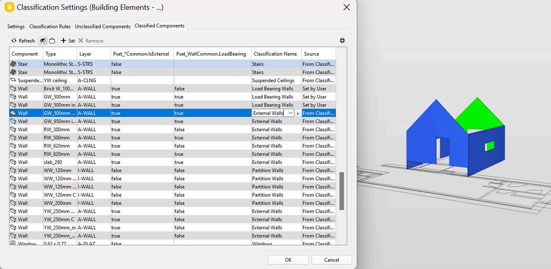
Once external wall changed into load bearing wall, the color attribute of the classification name changed.

M
G 7
O D E L C H E C K I N
Source:
23
Figure 61: Checking and resolving process for architectural and component check
Author
M O D E L
VI. Running the checking tool
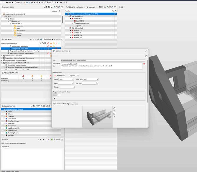
b.Hard Clash
To identify clashes, a clearance has to be set. In this case the checking identifies among the architectural model a component that have been duplicated at the same place.
1 Checking clashes reported
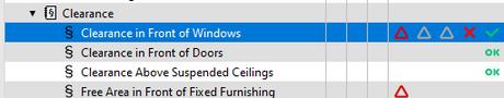
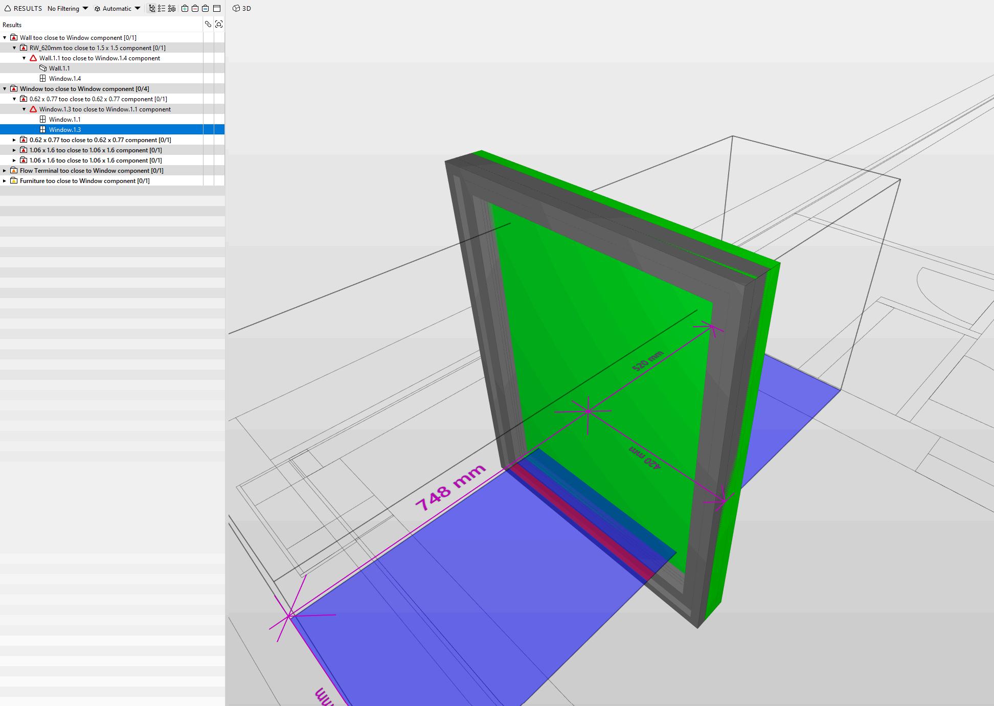
2 Approval or Refusal of clashes reported
c. Remarks
During the different checking, no project coordinate issue were reported. However few clashes were detected related to classification naming issues. Even this could have been solved in Solibri, these problems highlight identification issues between Revit and Solibri. This also could have been addressed in Revit by redefining the components’ name classification. For example, the foundation was defined as slab and then not recognised in Solibri, or the load bearing walls that were partially named as External walls.
3 Report clash
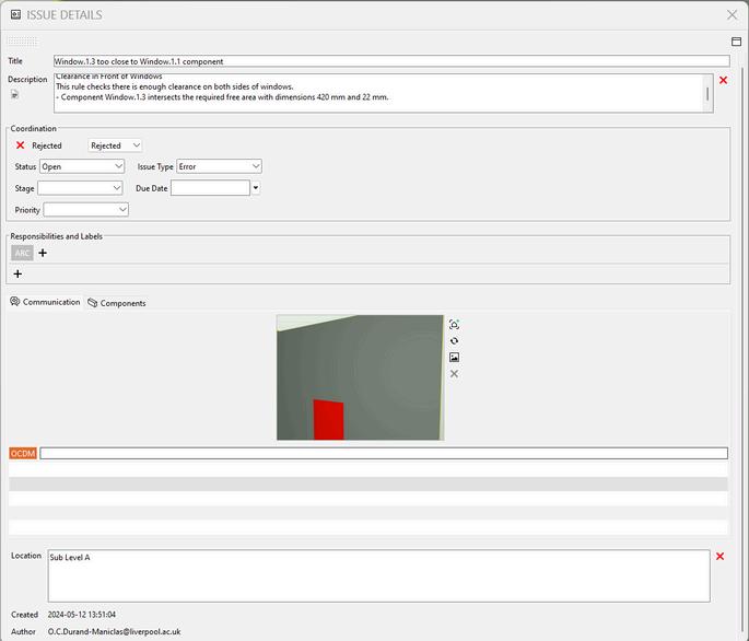
63: Issue reported due to a classification issue . Source: Author
7
C H E C K I N G
Figure 62: Soft clash reported due to a modelling issue Source:
Figure
Author
7 24
D. CONCLUSION
Issues
Clashes between elements were detected
Classification naming issues identified through missing identification of components.
Many clashes reported by Solibri, were irrelevant.
Solutions
A report was edited and shared with the in charge individual to modify the model
Checking component classification names in Solibri and changing them. this is possible, when the person that checks the model is fully aware of the model structure. Another option is to report identification issues to the individual responsible to modify it in Revit.
A manual and visual checking was necessary to identify the importance of each clash, then accept to signify that the issue was solved. If there is uncertainty, these have to be reported to the task team in charge.
Table 2: Overview of issues and solutions found in the model checking phase
In conclusion, defining the software needed in each stage is an important step as well as identifying the relevant classification naming. In this process
UNICLASS naming convention has the potential to solve misunderstanding and interoperability issue related to the naming classification. Besides, working closely with the modeling team or having the same individual doing the modeling and the coordination allows better understanding of the model clashes and results in time saving by decreasing iterative processes. Overall IFC data were successfully transmuted by Solibri.
E. LESSONS LEARNED
Defining classification naming convention in the first steps is at the utmost importance to check and coordinate the project properly.
Checking the classification names before running the checking. It is recommended to be done at the same time that unclassified components are sorted.
Having a single individual work on the model and check it, helps to save time along the clash detection stage.
M
C H E C K I N G 7
O D E L
25
4 D S I M U
A. MODEL PREPARATION
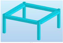
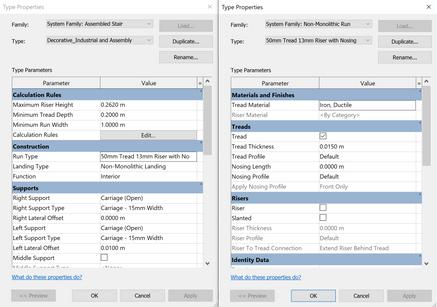
Prior to simulation in Synchro, the model required modifications to align with construction steps. Firstly, the timber structure was modeled using the beam system tool in the Revit Structure tab, and layers of roofs, floors, and walls were then separated based on construction sequencing.
B. IFC IMPORT
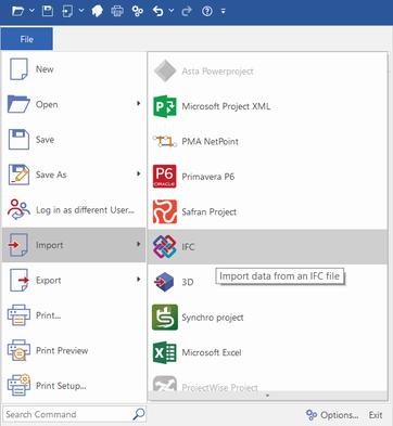
The first step is to import our IFC model in the Synchro interface. To do so, we have to choose file from the command bar, select import, then select IFC and afterwards choose our model.
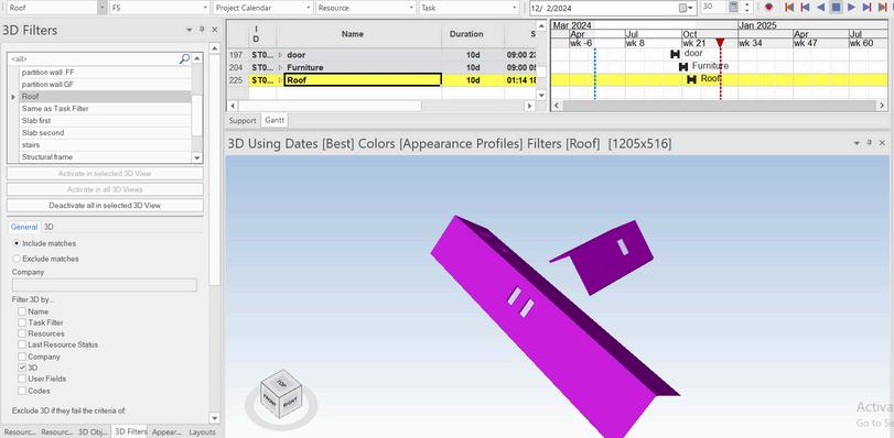
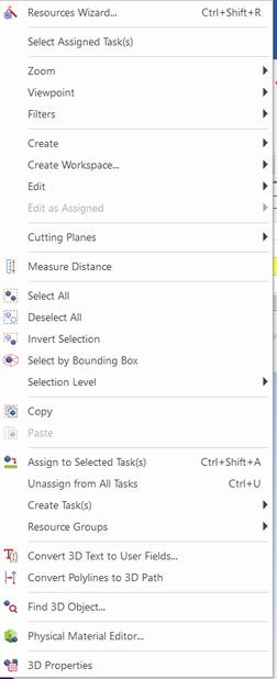
C. 3D FILTERING
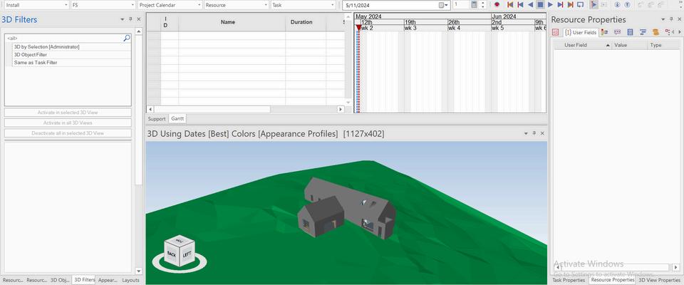
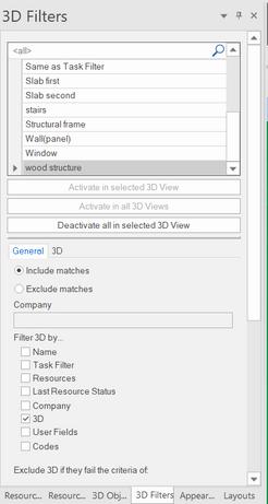
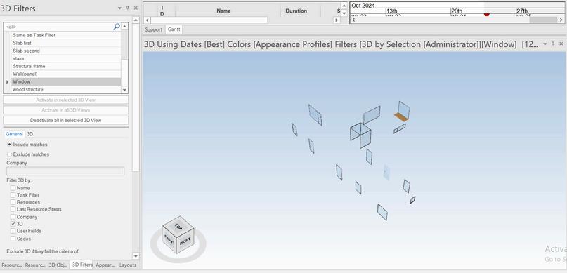
To do the 3D filtering, we have to make a selection, add a filter from the 3D filter tab and then mark them as selected. After that, anytime which we activate our 3d filter, we have access to our selection. This will be very helpful when we want to assign tasks in the upcoming steps.
T
O
8
L A
I
N
Figure 64Importing the IFC file in Synchro Source: Author
26
Figure 65: 3D filtering in Synchro Source: Author
4 D S I M U
D. APPEARANCE PROFILE
For each of our 3d filters, we have to make an appearance profile. By making the appearance profile we want the animation to be shown in the 4d simulation.
E.CREATING SCHEDULE
The next step is to create our schedule for the project. During this phase, we have to write our 3d filter names in the schedule, set the duration time for each of them and finally set a start date and end date for each one.
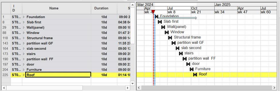
F.ASSIGN TASKS
In the final step, we have to assign the tasks to be able to see the results. To do so, we have to select the objects in one of our filters, right click and select assign tasks. We have to do this process for each of the filters.

L A T
O
8
I
N
Figure 66: Scheduling tab in synchro Source: Author
27
Figure 67: creating task for models in Synchro . Source: Author
4 D S I M U
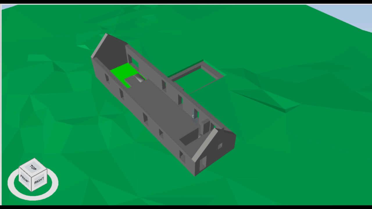
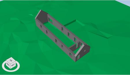
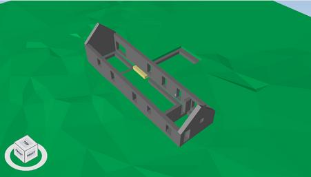
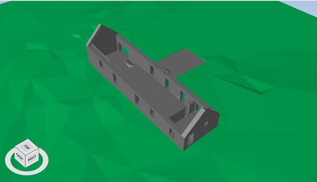
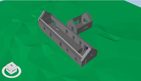
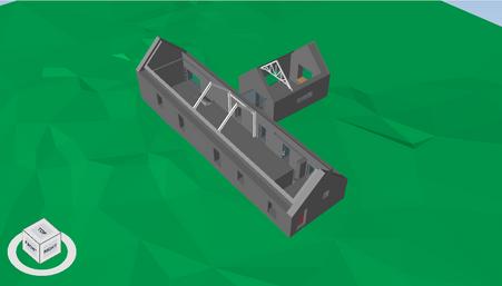
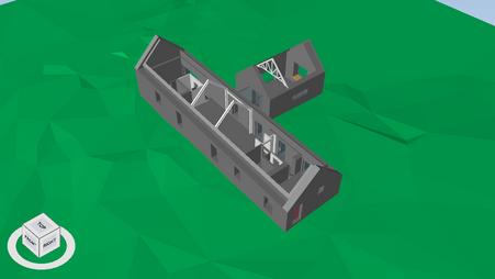
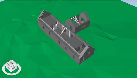
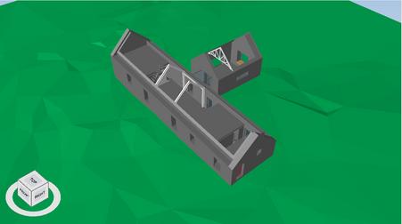
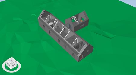
Here, we can see the result of our 4D simulation which has been done in 13 steps. As we are working on a heritage project, the project doesn't start from scratch and in the first pic in addition to the topography we have the old walls. These will be followed by foundation, Slab, panel, windows, metal beam, ground floor partition wall, first floor slab, stairs, first floor partition wall, door, furniture and roof.


8
L A T I O N
Figure 68: 4D simulation animation in Synchro . Source: Author Figure 69: Link to the animation in Synchro. Source: Author
28
Figure 70: 4D simulation process.Source: Author
D S I M U
G. CONCLUSION
Issues
Solutions
Synchro did not recognised the Curtain wall imported. creating a window similar to the curtain wall and then importing it.
Synchro did not recognised native file format (RVT) after importing. An IFC file was then imported to solve the problem
Some of filters included lots of elements and selecting them manually can be time consuming.
Use of resource properties tab to do the selection saved time
Table 3: Overview of issues and solutions found in the 4D simulation phase
In conclusion, Synchro is a very effective and easy to use software to do the 4D simulation. The process is pretty straightforward and does not require lots of training to be able to do a simple and basic 4D simulation. The most important thing in the process is to decide how to do the filtering before starting working with Synchro. It can be based on materials, object types or areas which has to be set before starting the project and the required data most be included in the model by the responsible person. This is why the collaboration between the modeler and Synchro operator is very important and is a note to remember.
H. LESSONS LEARNED
In the resource properties tab, only a few tabs will be useful in Synchro for 3D filtering, so exporting IFC with all the data is unnecessary.
The collaboration between the person in charge for the modeling software and Synchro is crucial as there might need to be some modifications on the file. So its better if the person in charge for Synchro has some knowledge about the modelling software to some extent.
In our project, we did the scheduling manually in Synchro as it is a small scale project, but for larger scale projects it is recommended to do the scheduling in an excel file and import as a XML file for better organization.
8
4
L A T I O N
29
MODEL CREATION LESSONS CAPTURED
MODEL COMPARAISON
Preparing an Excel file, or Information Delivery Specification (IDS) document to streamline the process in BIM software with IFC is highly recommended. L E S S O N S L E
one of the team members should have a basic knowledge of all processes and have a look at every project’s phase being progressed and test the software and IT infrastructure at the beginning.
Ensuring strong preparation. It includes providing a BIM Execution Plan, with a focus on information exchange requirements and several types of responsibility matrix to assign proper levels of information and detail, as well.
MODEL CHECKING
MODEL 4D SIMULATION
E D 9
A R N
30
A. LIMITATIONS & POTENTIALS
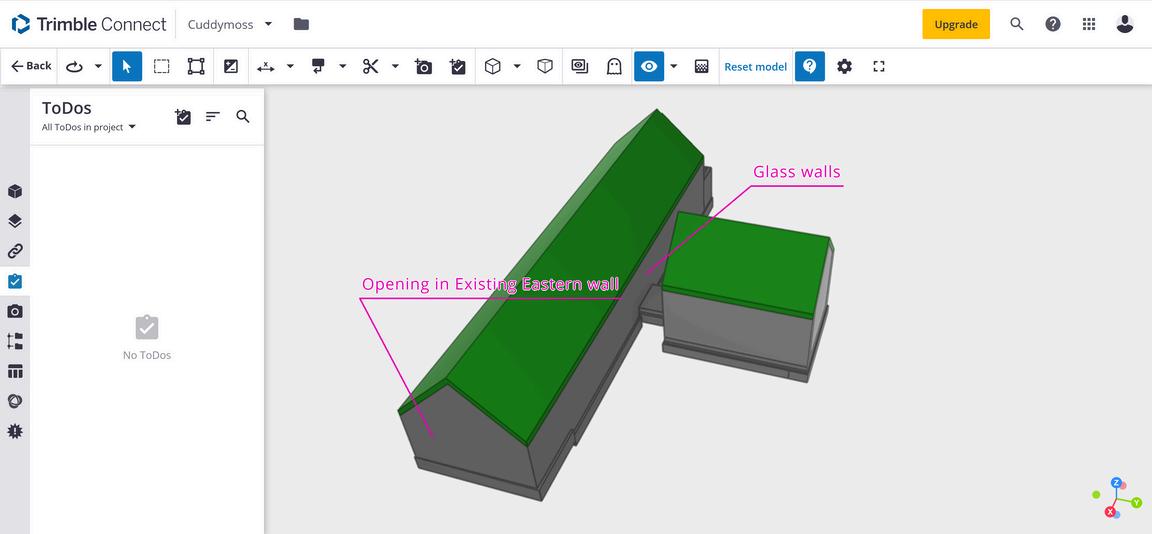
The process of sharing data to the CDE is not fully automated. Not only should the plugin be installed in the BIM tool, but each time it is necessary to sign into the CDE account and upload the newly modified model. Large files cannot be reviewed online. However, the project size was not excessive and the final file was uploaded successfully, the model did not open in the CDE for review.
However, in Trimble, roles can be defined and markups can be created on the model. The possibility of assigning tasks or mentioning specific members needs to be added and improved.
It is recommended to divide the model of such projects into different parts in the semi-final steps of the delivery process.
The construction details were added to the model and then classification was assigned to it. The model was used at the same time in 4D simulation and Solibri check. There was some issues in the process: The “Create Parts” tool in Revit could not separate the layers of elements such as walls or roofs for the 4D simulation since in the IFC export, these elements stuck together and did not remain separate. So they were separated manually.
the model contained large amount of unnecessary data for 4D simulation In Solibri check there were elements such as walls with incorrect sets of layers (due to the separation).
It is recommended to use different IFC exports with proper LOD and LOI for different tasks to prevent aggregation of unnecessary data. It would be better for the practice to provide predefined materials and object families (e.g. with proper layers) and also templates to facilitate the delivery process and prevent manual errors.
Some classes were not found and assigned correctly. Working with the classification system requires prior knowledge and basic familiarity with the system.
Although the project scale was not excessive, in large projects the semiautomated process of selecting elements and assigning standards can be time-consuming and error-prone.
It is recommended that the practice provide proper resources of knowledge about the classification system used for the staff and also define specific naming rules.
Table 4: Overview of limitations and potentials of the overall project
C
10
O N C L U S I O N
Limitations Potentials
C D E S O F W A R E C L A S S I F I C A T I O N 31
B. INTEROPERABILITY & BIM PLATFORM
According to ISO 19650, Guidance B, IFC is a wide spread format to share information consistently (UK BIM Framework, 2020). Along the model comparison stage, ArchiCAD showcased a better use of IFC, as data are transferred and identified effectively However, data-loss was a common problem throughout the data exchange process. Another challenge was assigning the classification system, UNICLASS, which is not a fully automated process and however a plugin in Revit was used to facilitate the process it was needed to select the objects manually. Moreover, checking UNICLASS in Solibri is not a straightforward approach and require extensive research, and updated information on UNICLASS checking ruleset in Solibri is a challenging task Nevertheless, defining a common classification system can help to tackle naming issues faced during the project delivery and improve coordination.
As previously discussed, due to broadband exchange issues, it is recommended to use an internal network CDE to share large files which will enable faster synchronisation. Additionally, the CDE and IT requirements should be considered at the initial stages. In this case, for instance, Trimble needed to be connected to the model by installing a plugin in Revit.
To define better exchange requirements, IDS document defines how objects, classifications, properties, values and units need to be delivered and exchanged (BuildingSMART, 2024) Moreover, it can serve as a combination for IFC (BuildingSMART, 2024)
C. BIM MANAGEMENT
In BIM process, every step should be clearly defined at the pre-design phase. It includes defining standards, modeling procedures, software, information exchange requirements (LOI, LOD, Responsible parties, Time), and team capabilities. It is also notable that the information exchanged information should be created precisely according to the step’s requirement. This will avoid delays, extra cost and further issues. Coordination throughout several BIM software requires an individual with sufficient knowledge to understand requirements and limitations prior to the start of the process.
it is also beneficial to train the task team to work effectively with CDE at the beginning. This will ensure clear understanding of information exchange protocol and several capabilities of the CDE. File naming convention plays an important role in a collaborative environment to streamline an effective use of the CDE as mentioned in ISO 19650 (ISO 19650-1 Figure 10). During the model development, this approach allowed members to have access to the last update model and find previous revisions easily.
Developing a detailed responsibility matrix played a crucial role in optimising time management, clarifying team responsibilities, and establishing clear project task hierarchy.
In overall, the project depicted the importance of setting an extensive preparation in BIM processes. It highlights the pivotal role of people and evaluating their capabilities in developing a successful BIM collaboration.
C
10
O N C L U S I O N
32
R E F E R E N C E S
4D construction simulation explained (no date b) https://www cmbuilder io/post/4d-construction-simulation-explained
ANN NISBET STUDIO no date Cuddymoss: A House for a Bird Watcher [Online] Available: https://annnisbet com/?p=3059 [Accessed 29/04/2024]
AUTODESK. no date-a. Classification Systems and Their Use in Autodesk Revit: Managing the “I” in BIM. Available: https://www.google.com/url?
sa=t&source=web&rct=j&opi=89978449&url=https://interoperability autodesk com/classificationmanager/downloads/Autodesk%2520Whitepaper%2520%2520Classification%2520Systems pdf&ved=2ahUKEwi5mIajo-iFAxXqQUEAHdx9DQsQFnoECCQQAQ&usg=AOvVaw0DQgtO9zSvX GWKDcr5N0 [Accessed 28/04/2024]
AUTODESK no date-b Autodesk Interoperability Tools [Online] Available: https://interoperability autodesk com/ [Accessed 28/04/2024]
Azhar, S. (2011) 'Building Information Modeling (BIM): Trends, benefits, risks, and challenges for the AEC industry,' Leadership and Management in Engineering, 11(3), pp. 241–
252 https://doi org/10 1061/(asce)lm 1943-5630 0000127
BRITISH STANDARDS 2021 BS EN ISO 19650 2: 2018 BSI Standards Limited
BuildingSMART (2024), Information Delivery Specification IDS - Available at: https://technical buildingsmart org/projects/information-delivery-specification-ids/ (Accessed: 16/05/2024)
CHOI, J , LEE, S & KIM, I 2020 Development of quality control requirements for improving the quality of architectural design based on bim Applied sciences, 10, 1-25 CROOK, L 2023 Cuddymoss by Ann Nisbet Studio named Scotland's best new building [Online] Available: https://www dezeen com/2023/11/30/cuddymoss-ann-nisbetscotland-best-building/ [Accessed 29/04/2024].
Djuedja Justine Flore Tchouanguem, Karray Mohamed Hedi, Foguem Bernard Kamsu, Magniont Camille and Abanda Fonbeyin Henry (2019) Interoperability Challenges in Building Information Modelling (BIM), Enterprise Interoperability VIII, Proceedings of the I-ESA Conferences 9, https://doi org/10 1007/978-3-030-13693-2 23
Eastman, C et al (2008a) BIM Handbook: A guide to building information modeling for owners, managers, designers, engineers and contractors http://ci.nii.ac.jp/ncid/BA87578739.
UK BIM Framework (2020) ISO 19650 Guidance B: Open data, buildingSMART and COBie
LEYGONIE, R , MOTAMEDI, A & IORDANOVA, I 2022 Development of quality improvement procedures and tools for facility management BIM Developments in the built environment, 11, 100075
Hamil, S. (2021) BIM dimensions - 3D, 4D, 5D, 6D BIM explained. https://www.thenbs.com/knowledge/bim-dimensions-3d-4d-5d-6d-bim-explained.
ROGAGE, K & DOUKARI, O 2024 3D object recognition using deep learning for automatically generating semantic BIM data Automation in construction, 162 Succar, B (2009) 'Building information modelling framework: A research and delivery foundation for industry stakeholders,' Automation in Construction, 18(3), pp 357–375 https://doi org/10 1016/j autcon 2008 10 003
TEJJY. no date. BIM Quality Assurance and Validation Checklist [Online]. Available: https://www.tejjy.com/bim-quality-assurance-and-validation-checklist/ [Accessed 29/04/2024]
WEYGANT, R S 2011 BIM Content Development: Standards, Strategies, and Best Practices, Newark, Wiley
33
F I G U R E S
Figure 1:Checklist of Quality Control (TEJJY, no date)
Figure 2: Overview of the workflow for preparing FM-BIM, outlining the checks conducted at milestones (Leygonie et al , 2022, p 9)
Figure 3: Synchro Interface Soucre Author
Figure 4: Visualization of a duplex apartment model.
Figure 5: Extracted building elements from the duplex apartment model: (a) a slab; and (b) a wall
Figure 6: Beams classification results of training data
Figure: 7-step method for automated IFC-based BIM object classification
Figure 8: Supported IFC import format in CAD/CAE software
Figure 9: Supported IFC export format in CAD/CAE software
Figure 10: Visualization of exported IFC in Revit, Archicad and Allplan
Figure 11: BIM platform workflow. . Source : Author
Figure 12: House picture (Ann Nisbet Studio, no date)
Figure 13:: Project Members in Trimble Connect Source: Author
Figure:14: Detailed responsibility matrix project. Source: Author
Figure: 15: File Uploader, Trimble Connect plugin for Revit Source: Author
Figure 16: Model overview in Trimble Connect Source: Author
Figure 17: Classification naming according to UNICLASS
Figure 19: Topography process Source: Author
Figure 20:: Component materials green wall definition ArchiCAD Source: Author
Figure 21:: Component materials red wall definition ArchiCAD Source: Author
Figure 22:: First Floor AutoCAD. Source: Author
Figure: 23: Ground Floor AutoCAD Source: Author
Figure: 24: North Elevation AutoCAD Source: Author
Figure 25: modeling process in Revit Source: Author
Figure25 bis: modeling process in Revi.Source: Author
Figure 26: modeling process in Archicad Source: Author
Figure 26 bis: modeling process in Archicad. Source: Author
Figure 27: Overal view of the models in Revt Source: Author
Figure 28: Geometrical issue (visibility issue). Source: Author
Figure 29: Geometrical issue (extra meshes. Source: Author)
Figure 30: Overal view of the models in Archicad. Source: Author
Figure 31: Interior view of the models in Archicad Source: Author
Figure:32 imported IFC wall properties Source: Author
33: Ground floor plan in imported IFC. Source: Author
Figure 34: Ground floor plan in original Revit file Source: Author
Figure 35: imported IFC wall propertiesSource: Author
Figure: 36 Ground floor plan in imported IFCSource: Author
Figure 37: Archicad wall properties Source: Author
Figure 38: Ground floor plan in original Archicad file. Source: Author
Figure 39: Original Revit file wall properties. Source: Author
Figure 40: wall parameters plan in original Revit file Source: Author
Figure 41: wall parameters in the imported IFC Source: Author
Figure 42: window parameters in the imported IFC Source: Author
Figure 43: window parameters in the inported IFC Source: Author
Figure 44: Object type in the imported IFC. Source: Author
Figure 45: window parameters plan in original Archicad file Source: Author
Figure 46: object type in the original Archicad file Source: Author
Figure 47: Autodesk interoperability plugins (Autodesk, no date-b)
Figure 48: Picking discipline Source: Author
Figure 49: Classify non classified components. Source: Author
Figure 50: Creation of Topography name classification . Source: Author
Figure 51: Timber structure model. Source: Author
Figure 52: Interior- Living Room . Source: Author
Figure 53: Dimensions Level Checking 1. Source: Author
Figure 54: Dimensions Level Checking 2 Source: Author
Figure 55: Markup tool Showing a clash. Source Author
Figure 56: BIM Data checking with IFC by identification, location, and quantities. Source Author
Figure 57: IFC Data in Solibri Source Author
Figure 58: Changing classification name from Slab to Foundation. Source Author
Figure 59: Selection of component to check . Source: Author
Figure 60: Pop-up window to select ruleset in Solibri. Source Author
Figure 61: Checking and solution process for architectural and component check. Source: Autjhor
Figure 62: Soft clash reported due to a modelling issue Source: Author
Figure 63: Issue reported due to a model discipline classification issue . Source: author
Figure 64Importing the IFC file in Synchro. Source: Author
Figure 65: 3D filtering in Synchro Source: Author
Figure 66: Scheduling tab in synchro Source: Author
Figure 67: creating task for models in Synchro Source: Author
Figure 68: 4D simulation animation in Synchro Source: Author
Figure 69: Link to the animation in Synchro Source: Author
Figure 70: 4D simulation process.Source: Author
34
Figure
T A B L E S
Table 1: Overview of issues and solution found in the model comparison phase Source: Author
Table 2: Overview of issues and solutions found in the model checking Source: Author
Table 3: Overview of issues and solutions found in the 4D simulation .Source: Author
Table 4: Overview of limitations and potentials of the overall project. Source: Author
35
