5 minute read
Chosen Design For Floatation Device
CHOSEN DESIGN FOR FLOATATION DEVICE
After much deliberation, our final decision was that the sixth design idea transpired as the strongest competitor, and indeed the one with the greatest prospects for functional effectiveness and success. The design works such that the tower may be built in a dry dock, and that dock is then flooded upon completion of the tower so as to float it, in readiness for being moved out to the required location. Once the water has lifted the tower off the ground to a satisfactory level, and the water level inside the dock is equivocal to that of the sea on the far side of the dock-gates, they are opened, and the tower’s journey begins. This launch procedure would have to take place in the mid- to late afternoon, because this is high tide on the North Sea, and this is essential for ensuring that there is adequate depth in order for the tower to leave the dock without scraping on the sea floor.
Advertisement
The pulling power comes, in the main, from a leading ocean-going tug, whose purpose is rudimentarily to tow the tower out of the dock. The actual tow-line arrangement, in terms of number of cables and their optimum fixing positions, is to be ascertained during the testing process.
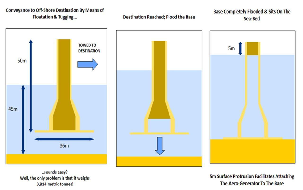
PROCEDURE DIAGRAM FOR CONVEYANCE OF TOWER
Source: Primary Image
Created: 14th December 2011
In the meantime, two harbour tugs (one on either side) are there to manoeuvre the tower on a finer level, steering, pushing or pulling it here and there as required, so as to control both its direction and its position relative to the ocean-going tug in front. This is an essential part of the process, because the ocean-going tug in front will simply not be capable of preventing the tower from drifting from side to side as it trundles along behind it, and the harbour tugs are therefore play a crucial part in keeping the tower on course and preventing unwanted strains on the tow-ropes and the manifestation of health and safety risks to the personnel involved.
In all three of the tugs, the cables must feature a quick release system, in which the cables can quickly and instantly be released in the event of the tower falling over. By disconnecting the tugs from the structure in this circumstance, the safety of the crew can be maximised. Otherwise, the tower would pull on the tow-lines and hence pull the tugs over if it were to fall completely, hence putting the crew at risk.
Once the tower reaches its location, it is then released from the floatation jacket, and the water inlet valves are opened in that same instance, such that the tower may begin to flood and consequently sink under the weight of the water it is taking on [this is all depicted in the previous diagram]. The tower will be sunk in waters of depth 45 m, such that 5 metres’ worth of tower protrudes above the surface, with which to build the wind turbine.
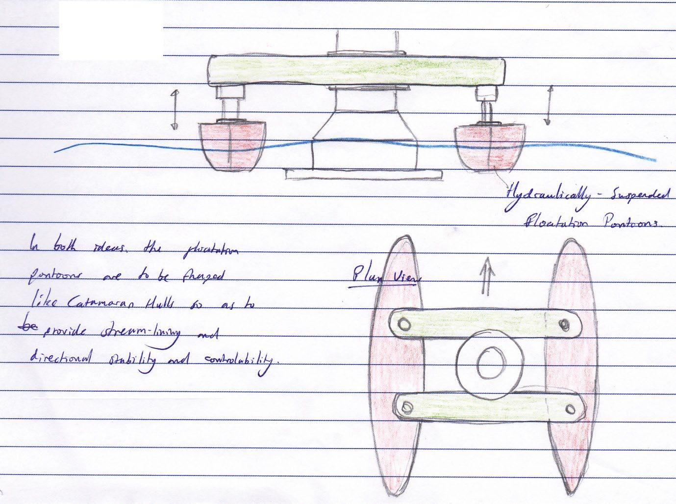
In regards to stabilising the tower whilst being moved, design six was selected as being the most effective design choice, on account largely of its simplicity and relative ease of construction. Nonetheless, not only is it a very simplistic design, but it is also the one that conformed most closely to the Specification, and it is for this reason also that design six was selected. As per the requirements laid down in the Specification, the device provides the structure with an all-round stability, making use of the Buoyant Forces produced by intermittent submersions of the floatation pontoons during tilt of the tower. It is designed to resist the tilt of the tower gently, but with a firm, underlying control, and provides effective shock absorbency of the tower’s more sudden movements, via the piston arrangement that suspends the floats beneath the framework. It also makes provision for damping of these movements, through the very same system just mentioned, such that the tower can be brought to a halt as quickly as possible. This comes from the effect of pressurising the gas inside the piston by compressing its volume.

ORTHOGRAPHIC VIEWS OF DESIGN #6
Source: Primary Sketch
Created: November 29th 2012
Therefore, this design was considered to be one of the very successful options for selection. To add to this, the single, out-of-water point of attachment, with which the pontoon support structure is fitted onto the tower, will help in making the process of both attaching it, and subsequently deploying it, very easy indeed, unlike design five, which would require an entire sub-aqua team just to access the detachment point. The structure can simply be set up adjacent to the tower and clamped on, and once out at sea, the tower can then simply be dropped out from inside, meaning these are also key Specification points that this design is successful in meeting. Again, the actual height at which this structure should be fitted is to be determined during the testing process. That said, as a provisional requirement, it should be mounted such that that tower’s Centre of Mass is as close to the pivot point on the surface of the water as possible, so as to minimise the Turning Moments produced by the tower's weight during a tilt.
Another aspect in which design six has the upper hand over design five is that it does not require any alterations to the existing tower (another Specification point that has been successfully adhered to by this design). Moreover, unlike the first four designs, this one in particular utilises directional, hydro-dynamically-streamlined pontoons in order to ensure ease of directional control and a smooth, efficient glide through the water. By reducing the cross sectional area of the pontoons that is exposed to the flow of water, the Drag Co-efficient, wake thickness and overall Drag Forces exerted onto them may be minimised. This, as said, helps too facilitate smooth and easy movement through the water.
More detailed discussion of this design may be found in the table seen previously.
That said, the strengths and performance characteristics that we were able to discuss at this stage were of course hypothetical, as the design was then only based upon the drawings we had. Therefore, testing was to form part of the next crucial stage so as to obtain an insight into how effective this design actually was in the flesh.


