12 minute read
Mathematics Behind the Design
MATHEMATICS BEHIND THE DESIGN
Introductory Theories:
Advertisement
Possessing a rudimentary diagram that depicts a particular concept, or even a more elaborate one for that matter, is a far cry from being able to appreciate exactly how that design is likely to perform. A bit of ‘number-crunching’ is therefore an essential leg of the journey towards being able to accomplish this.
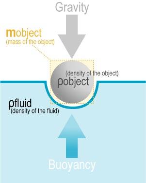
The fundamental principle behind the floatation of this tower is that of the Buoyant Force, which states that the force of upthrust (the Buoyant Force) in a particular submersion is equal to the total weight of all the water that the tower displaces in that submersion.7
Moreover, in order for the tower to stand any chance of floating, it must produce a Buoyant Force whose magnitude is equal to its own weight. In this circumstance, the tower’s weight will continue to act downwards, but the equal-magnitude Buoyant Force acting upwards in the opposite direction will effectively cancel it out (and vice versa), hence establishing an equilibrium of balanced forces, in which the tower will consequently stay afloat.
Therefore, by combining this with the theory of Buoyant Forces, it can be deduced that the tower must displace a quantity of water with such a volume that the weight of that water collectively is equal to the weight of the tower.
BUOYANT FORCE DIAGRAM
Source: askphysics.com
Retrieved: April 7th 2012
Step 1
This leads us to the first step of this process: calculating the weight of the tower. This was an inevitably arduous process, and one that involved breaking the structure down into separate, individual sections, and subsequently calculating the mass of each one in turn, with regards to their volumes and respective densities. Particular care had to be taken in view of the fact that the bottom two sections have a different density (2500 kg.m-3) to the rest of the tower (1800 kg.m-3). Incidentally, this did transpire as quite a major source of error in our first attempt at working this out, which we resolved in the only way we could: starting again!
The cone-shaped section of the tower proved to be a particular mathematical challenge, which we tackled by way of treating the situation much as if we were looking to calculate the volume of a torus. In doing this, we were successful in taking a seemingly complex and somewhat daunting calculation, and converting it into something more familiar and therefore something we felt more comfortable in addressing, The only difference was of course that,
instead of the cross section being circular, it was more of a trapezium, as this is the shape obtained when a cross-section is taken through the wall of the cone at one side.
Eventually, we arrived at an answer: the total mass of the tower is equal to 3,814,688.4 kg, giving a total weight of 37,422,093.2 N (found by multiplying this mass by the Earth’s surface Gravitational Field Strength, 9.81 N.kg-1).8
From our previous discussion, it is possible to deduce that this is in actual fact the weight of the water that the tower must be capable of displacing during a particular submersion, if it is to stay afloat. 3,814,688.4 kg of water must therefore be displaced, and with a density of 1000 kg.m-3, this equates to 3,814.7 m3 .
By comparing this to the total volume of the tower, it is possible to infer what proportion of the tower’s complete body must be immersed in order to displace this much water. Eventually, this works out such that the very bottom edge of the tower’s base sits at 7.2 m below the surface of the water, assuming that the tower floats in an upright position as it would on dry land.
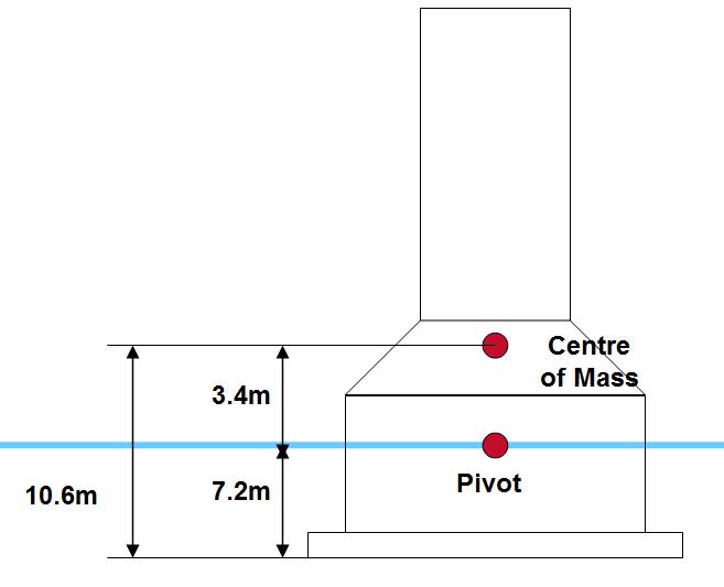
Incidentally, the tower will in fact pivot about the point at which its vertical centre line intersects the surface of the water. This will therefore be 7.2 m above the base of the tower.
Step 2
So, we know now that the tower has the ability to float, but in the grand scheme of things, does this really tell us very much? Well, no, not really. For example, being able to float is all well and good, but what use would this be if the tower kept flipping up-side down? The assumption just mentioned is therefore an extremely important one, but what would be more use to us is obtaining a mathematical feel for the tower’s stability. One way in which this may be done is to pin point the tower’s Centre of Mass.
We did this using a Plumb-Line Method and a simple 2-Dimensional Model, which we fabricated carefully in the engineering workshop at the University of Kent, Canterbury, whilst on the Residential Visit.
The major difficulty we had, which we stumbled across almost immediately, was that, whilst the real tower has varying densities and mass distributions throughout different sections of its structure, those of the 2-D Model were consistent throughout, and so could not hope to provide an accurate representation. This we resolved by simply looking at the whole mass of the tower, in more holistic terms. We essentially split the tower into two separate halves (the divide being at the top of the coned section), and hence observed that the masses of the two halves (top and bottom), were bound by the ratio 1:8.74 respectively. This we endeavoured to emulate by cladding the bottom half of our 2-D Model with MDF blocks, until it too was as close as possible to being 8.74 times as massive as the top half.
The major hindrances we experienced at this point were acombination of time constraints, and the somewhat limited availability of MDF sheets of an appropriate thickness. Nevertheless, this task was completed fairly successfully, all things considered, and it actually turned out that the bottom half was in factaround 8.8 times heavier than the top half.
Once the model was finally completed, testing could then begin. The following method was employed:
• Drill a small hole (no more than 2mm in diameter) in each of the four corners of the model
• Suspend the model from one of these corners by passing a pin, rod or nail through the hole and clamping it firmly to the desk using a G-Clamp (NB: the model MUST not be obstructed from swinging freely)
• Suspend also from the pin, a Plumb-Line (in this test, we used a heavyM12 Stainless Steel Bolt on a string)
• Allow both to come to rest. At this point, the Centres of Mass of both objects will be directly beneath the point of pivot, so it stands to reason that any straight lines that connect the point of pivot and the Centre of Mass will be vertical. As such, if we could just copy such lines onto our model, we would effectively produce a linear locus: a straight line, somewhere along which the Centre of Mass must lie. This we achieved by ‘tracing’ the line made by the string of the Plumb-Line, knowing that this too hung vertically, onto the model.
• Repeating the experiment for the other corners of the model produces four separate lines, along all of which the Centre of Mass has to lie. Of course, the only place where a single point can be on all four of the lines at once is where these lines cross, and indeed, it is here that the Centre of Mass is found.
When we completed the experiment, we discovered that the lines did not so much cross each other all at the same point, as they did cross in pairs, at four different places. This uncertainty was alleviated by way of placing the Centre of Mass in a relatively central position inside the small area enclosed by these four lines.
This resulted in finding the Centre of Mass of the tower at a height of 10.6 m above the base. As predicted, this is quite low down within the tower’s structure: we were anticipating this, because here is where the vast majority of the tower’s mass is concentrated
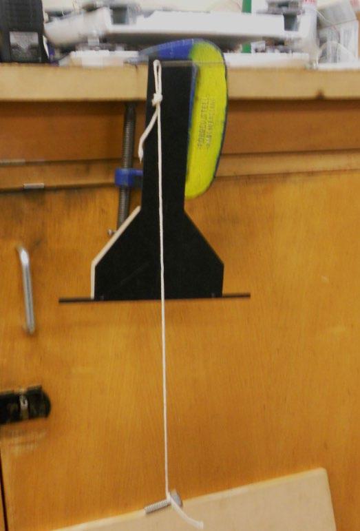
PLUMB-LINE EXPERIMENT
Source: Primary Photograph
Taken: December 13th 2011
Step 3
So, having established the position of the Centre of Mass, and that of the pivot point, the resulting gap that lies between the two (a vertical height of 3.4 m) can now allow us to build up a picture of the tower’s stability.
The implication of this height difference is that the tower structure, when floating onits own, is Inherently Unstable. This means that the tower has no capability of righting itself if it tilts over, and any slight tilt to one side will therefore mean that the tower is doomed to fall over completely.
This is because of the effect of Turning Moments. The weight of the tower is a force, which acts vertically and originates from the tower’s Centre of Mass. Moreover, the tower’s motion will always pivot more or less about the central point fixed on the surface of the water, 7.2 m vertically above the base of the tower. As soon as the tower is tilted to one side, by the action of a wave, say, the Centre of Mass, and indeed the line of action of the Weight Force acting from it, are instantly displaced from their central position above the pivot point, and a horizontal displacement is therefore immediately established between them. This enables the weight force to produce a Turning Moment, which again acts about the central pivot point on the surface of the water and works to topple the tower completely.
This Moment can be expressed using the following formula:
Where:
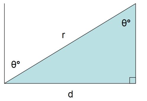
���� = Torque due to Weight Force (N.m)
���� = Weight Force (37,422,093.2 N)
���� = Straight line distance between the two red dots (Centre of Mass and Pivot Point, 3.4 m)
���� = Perpendicular distance between line of action of weight force and pivot point (m)
���� = Angle of tilt (°)
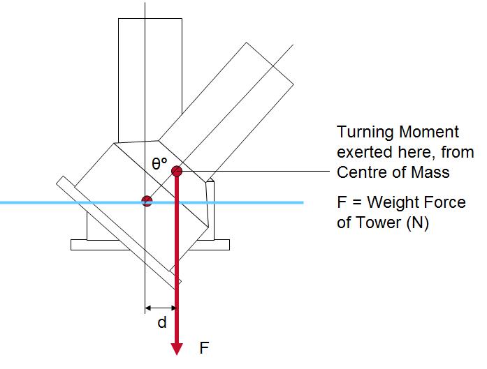
As the tower leans further and further, the angle is increased, and the Centre of Mass is hence displaced further from the central position. The consequence of this is such that the magnitude of the Turning Moment produced by the Weight Force is increased, meaning the effect is precipitous, because it becomes more and more severe as the tower leans further. Once tilted, the effect is therefore completely irreversible, unless some immense force is applied to counter it. This highlights the importance of the floatation pontoons that have been designed so far. In view of this information, they have become an extremely important, even vital piece of equipment, crucial for the safe and effective conveyance of the tower structure through the water and for preventing it from toppling over completely. Without it, the tower will be completely unstable, and as such, completely unable to support itself in choppy waters.
The pontoons used in such a support structure must function in such a way that they can directly and fully oppose the Turning Moments produced by the weight of the tower. As the tower leans over to one side, its weight is obviously exerting an incredibly strong Turning Moment downwards, in the direction of the water. In doing so, it presses the floatation pontoon on that side down into the water, hence culminating in a Buoyant Force that acts upwards, in response to the submersion of the pontoon. In order to stop the tower from leaning further, and even push it back up again, that Buoyant Force would have to be of such a magnitude, and applied at such a distance from the pivotal point, that the Turning Moment it leads to is equal to, or even greater than, that produced by the tower’s weight initially.
Research conducted previously had disclosed thatthe average wave height on the North Sea is around 2.5 metres. A combination of sequential trigonometric processes and meticulous visual analysis of the tower structure enabled us to determine the sorts of torque loadings that
the tower would be likely toexperience as a result of its instability in a lean, in a normal North Sea environment. Assuming that a single wave of 2.5 metres in height acts on the very outer edge of the tower’s base, pushing this part of the structure up by that height, we came to the conclusion that the tower structure would tilt accordingly about its pivot, through an angle of 7.8°. This would consequently displace the Centre of Mass by 0.46 m from the centre, instigating a Turning Moment of 17245785.2 N.m. If the pontoon is to be able to hold the tower there, and prevent it from leaning over any further, it must therefore also exert a Turning Moment of this magnitude, but back in the opposite direction so as to counteract the lean of the tower. This Turning Moment is of course provided by the Buoyant Force that acts upwards in response to the submersion of the pontoon. With a slanted radius between the centre of the tower and the Centre of Pressure at which this Buoyant Force is exerted on the pontoon, of 21 m, and an angle of tilt again equal to 7.8° (leading to a perpendicular distance of 20.8 m), this would require a Buoyant Force of 828897.0 N.
In addition to this, the tower will of course have to withstand buffeting from North Sea winds as well. Fundamentally, forces are exerted onto an object by the passage of a high-speed airflow (like wind) because of the Drag that that object makes with the air passing over it. So, assuming that:
• Theair has a Drag Co-Efficient (CD) of 0.9 • The air has a density (ρ) of 1.225 kg.m-3 at 15°C and 1 ATM (NASA Lewis Research Centre; April 6th 2012) • As disclosed by our research, average North Sea wind speed (v) falls around the value of 30 mph, equalling 13.4 m.s-1 • The airflow exerts its associated drag force onto the top section of the tower (assuming that below this level, the wind will be too turbulent to exert any such forces), giving a crosssectional area exposed to the airflow (A) of 240 m3 (height 30 m, diameter 8 m) • Using the formula D = ½CD ρv2A
The total force exerted by the wind in these conditions is equal to 23,785.3 N. Again making an assumption, this time that the force is exerted and distributed evenly across the entirety of this area, there will be a Centre of Pressure (located in the Geometric Centre of the area), at which point all the drag forces appear to act together.
Due to the dimensions of the tower, and its position in the water, this Centre of Pressure works out at being 27.8 m directly above the tower’s pivotal point on the surface of the water, hence producing a Turning Moment of 661,232.6 N.m.
As before, this Moment will have the undesirable effect of toppling the tower, and once it does, the precipitous effect will againkick in.


