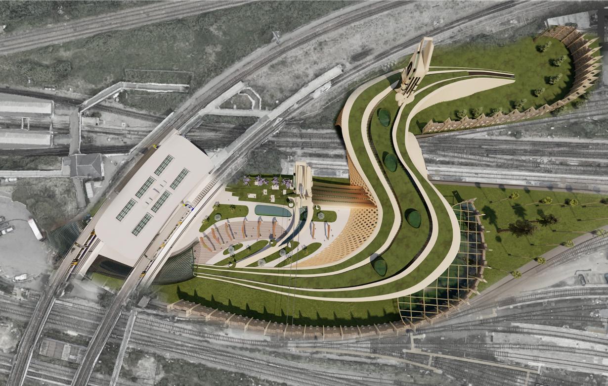
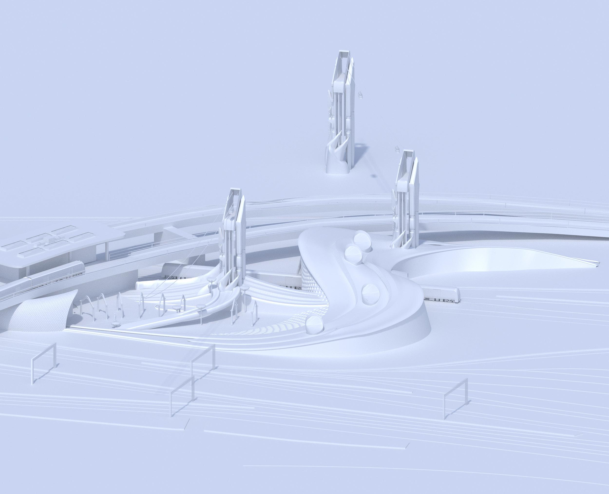
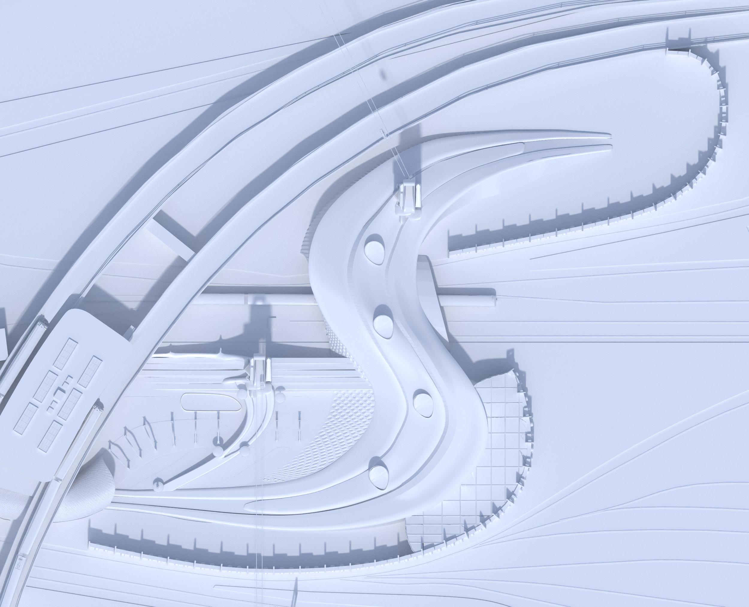
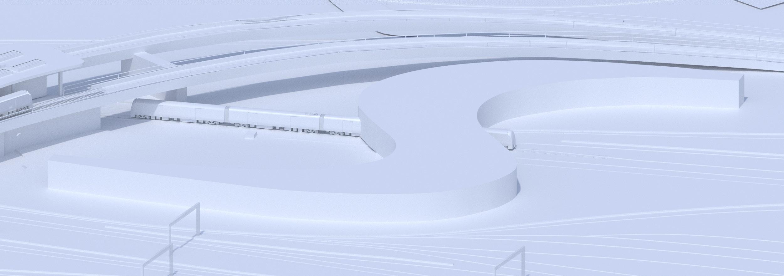
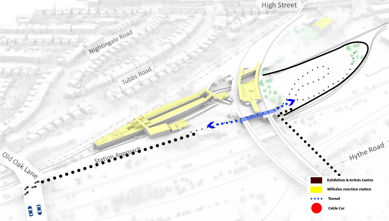
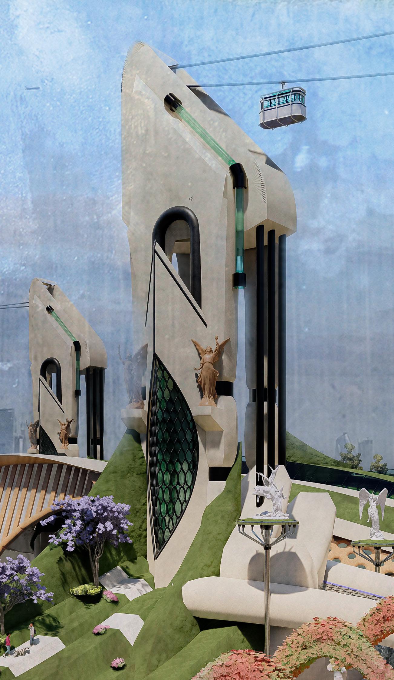
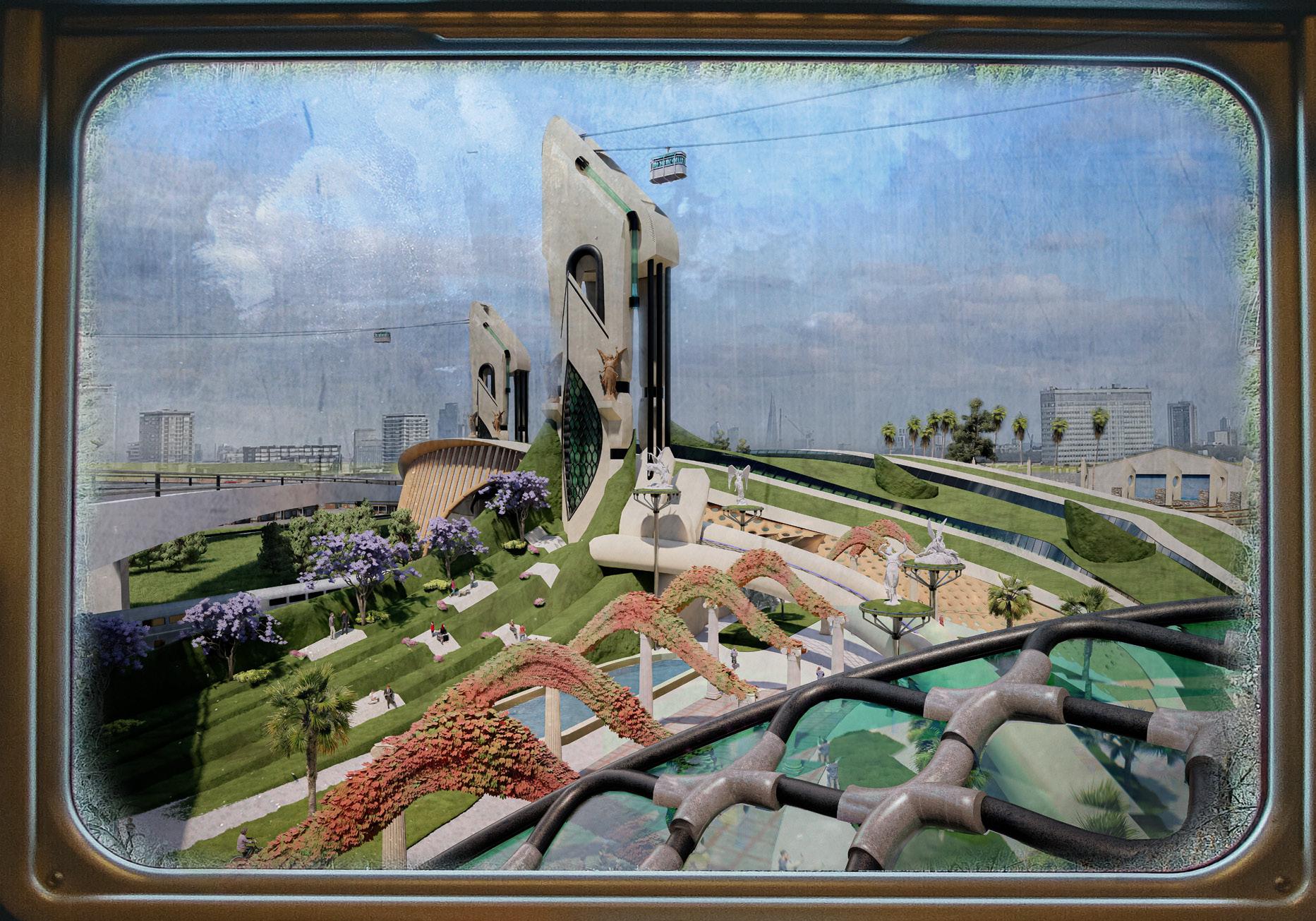
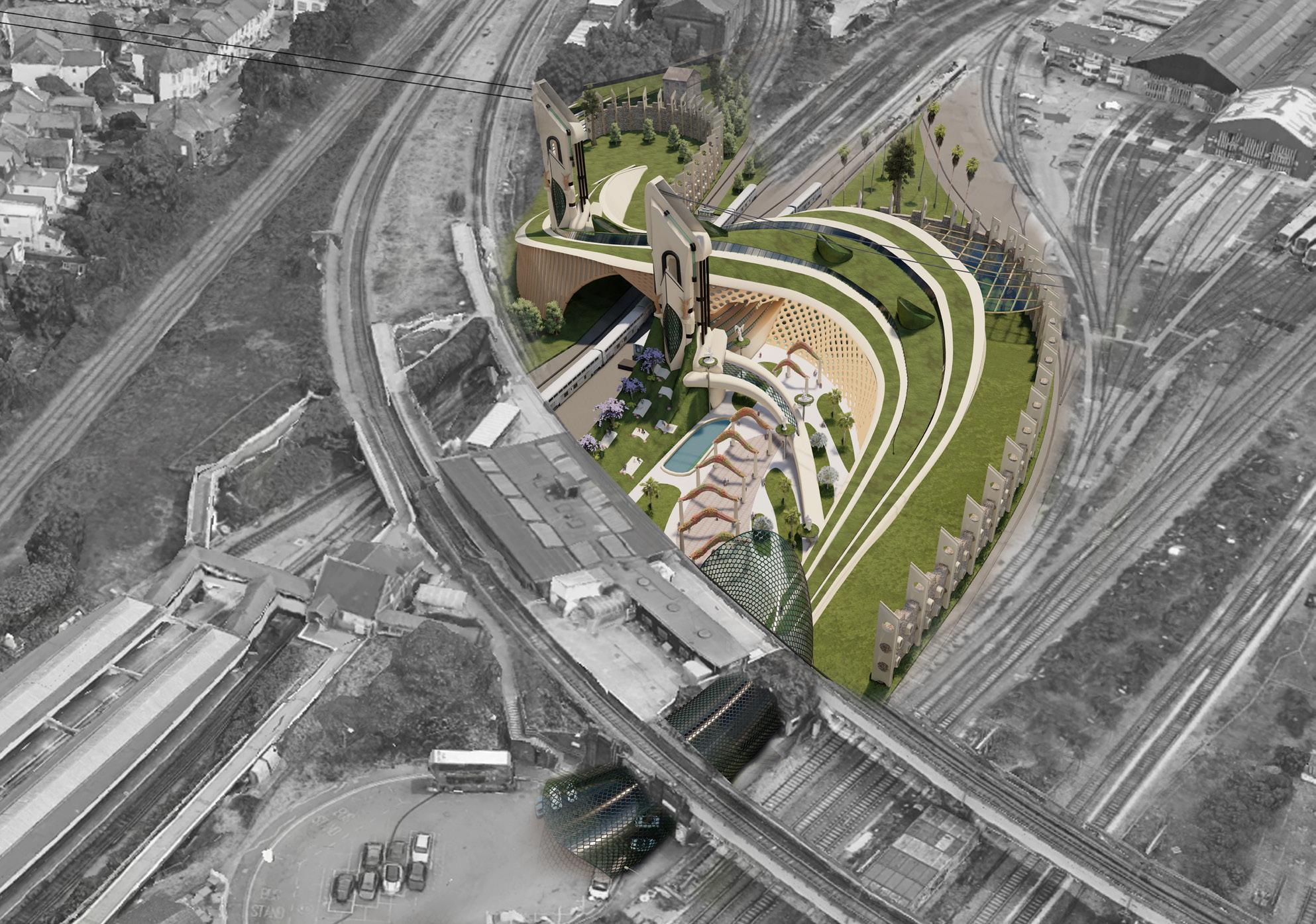
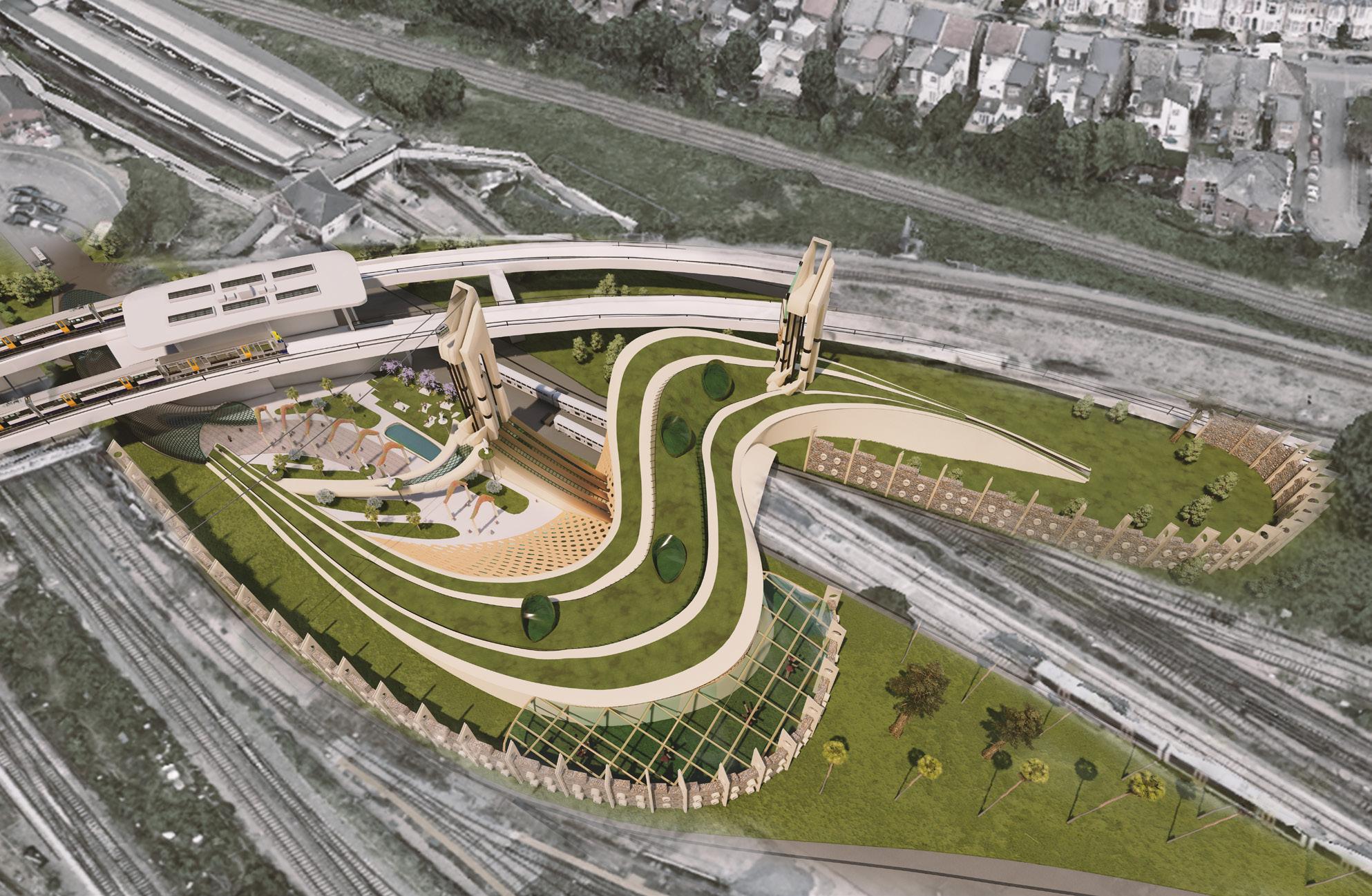
EXHIBITION CENTRE: WILLESDEN JUNCTION STATION EXTENSION
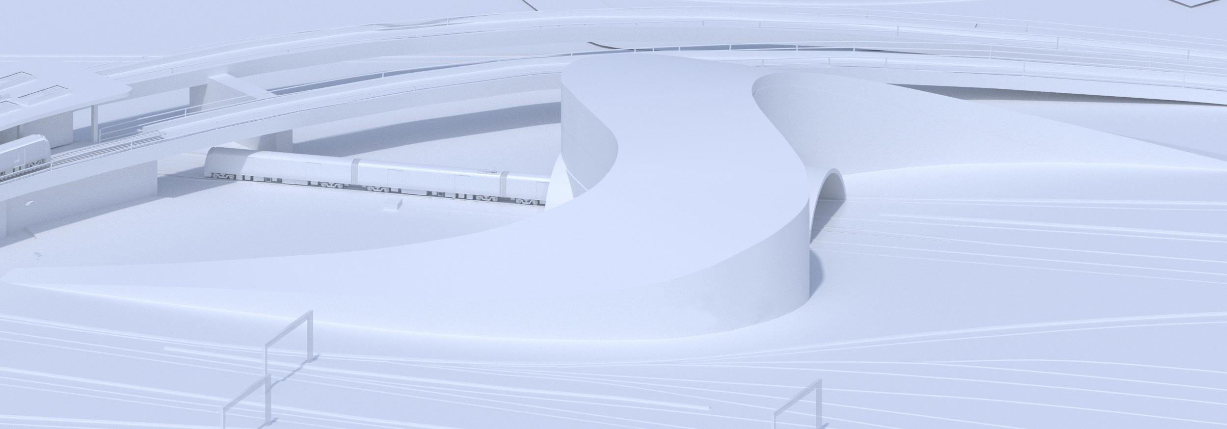
• SCALING UP IN MIDDLE PART: to create a tunnel for railway
STAGE 1
STAGE 2
• SCALING DOW AT TALE PART: to create ramps
STAGE
STAGE 4


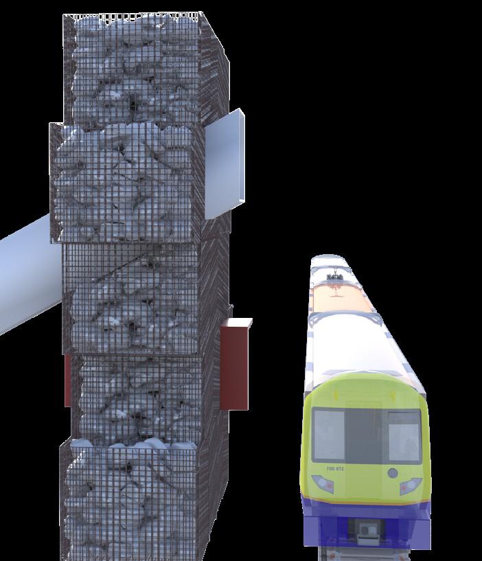
• Adding gabion walls protects project from railway and providing it the desired privacy
• Adding green areas and water features to project
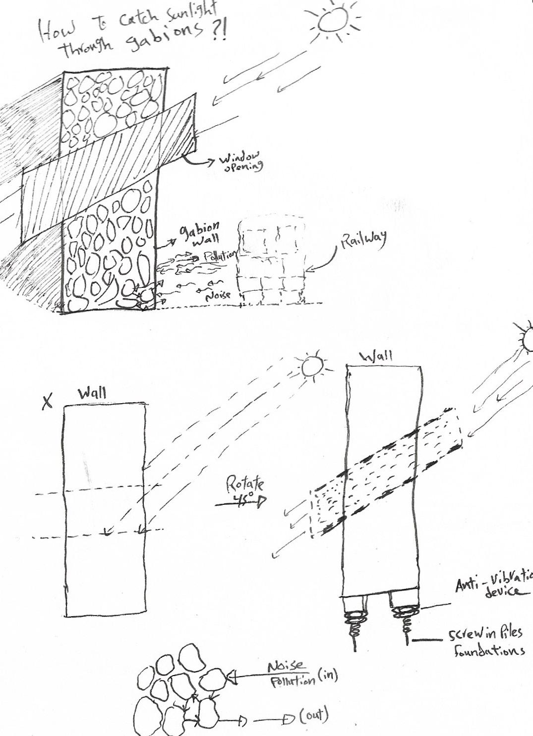
• Skylight facing south to take advantage to sunlight
2
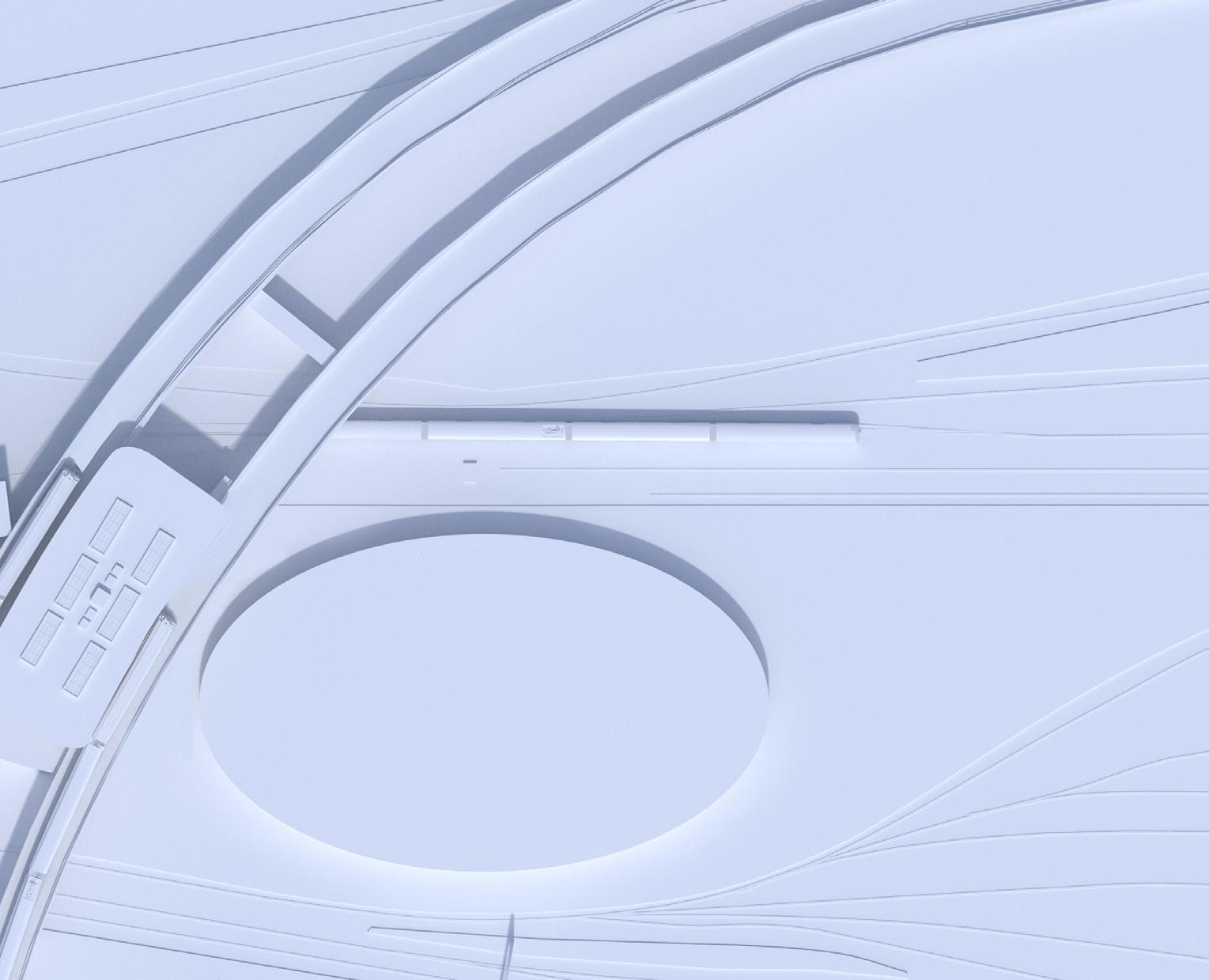
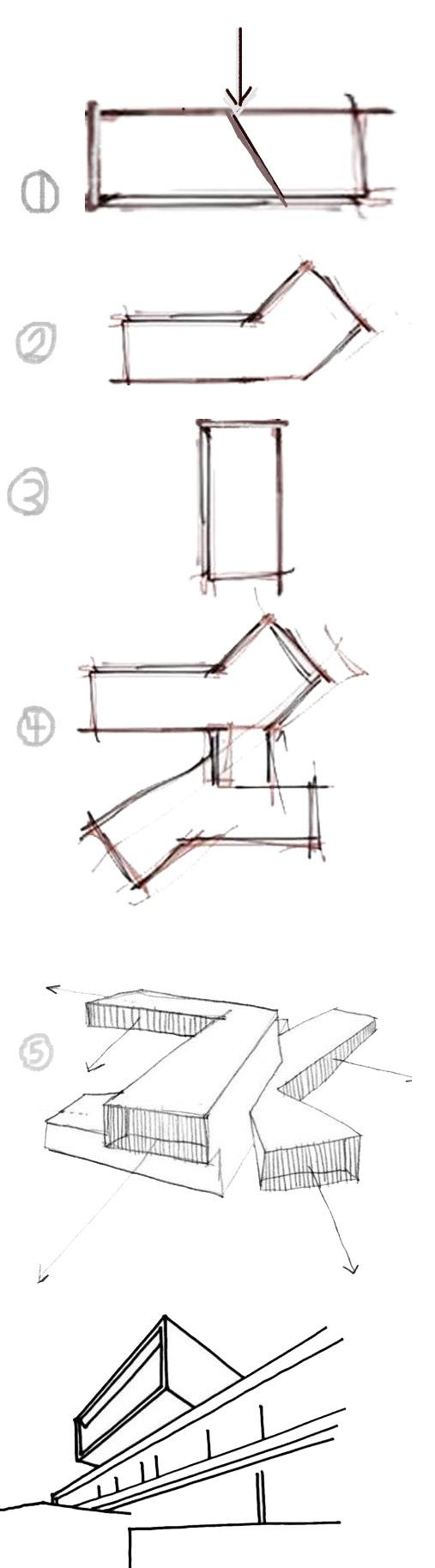
FORM
SCALE CIRCLE Willesden Junction station CUT OUT RED PART HORSE-SHOE SHAPE
HORSE-SHOE SHAPE
in
GENERATION
MIRROR
used Indesign
the process
RAILWAY
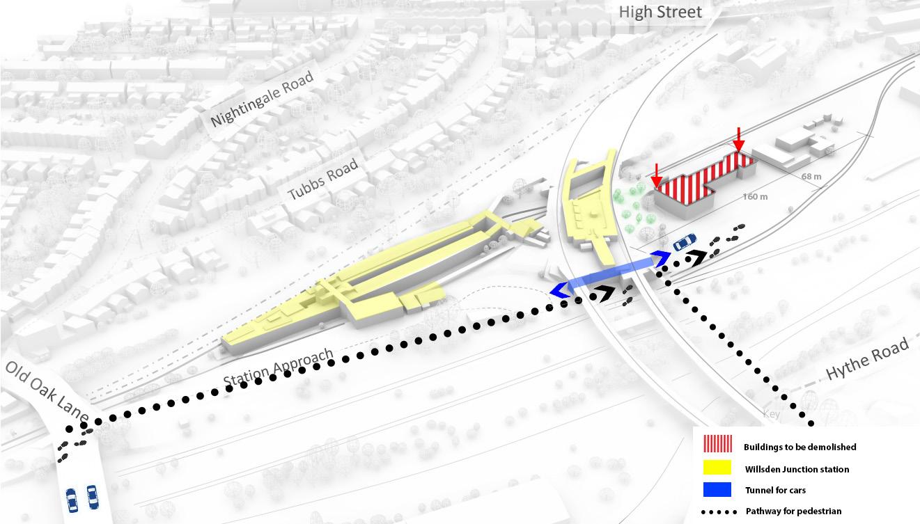
CABLE CAR TOWER 2 CABLE CAR TOWER 2 CABLE CAR TOWER 1 TOWARDS HS2 ENTRANCE Art Centre area Tubbs High St. (Neighbourhood) Exhibition RAILWAY RAILWAY
3 Cable cars added for transportation.
EXTERIOR WORKSHOP GABION WALLS GABION WALLS ENTRANCE
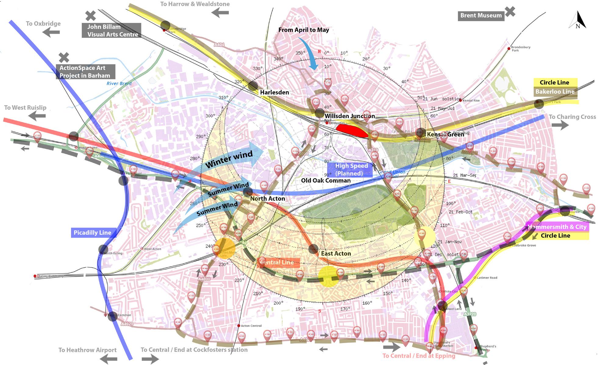
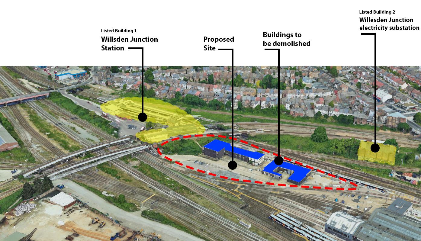
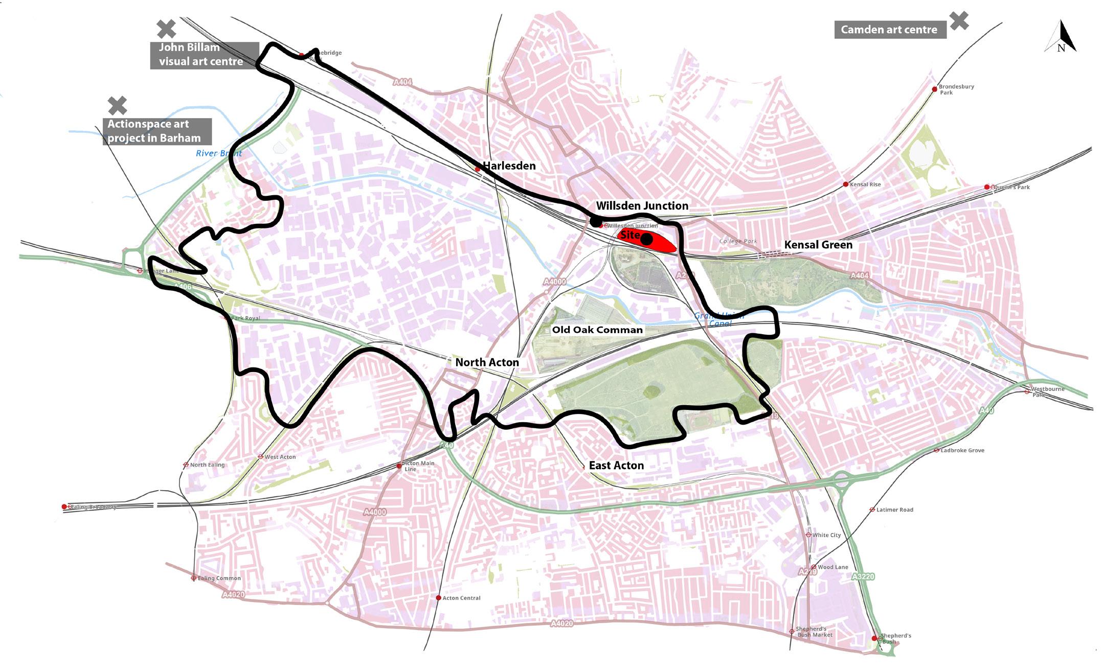
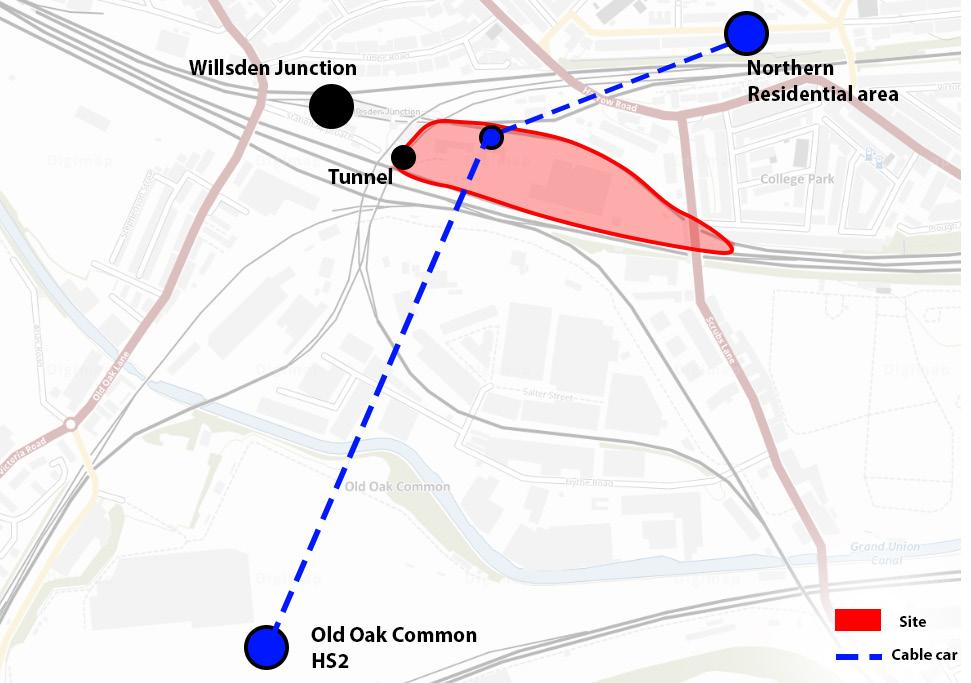
3 MAPS & SITE ANALYSIS used Indesign in the process

4
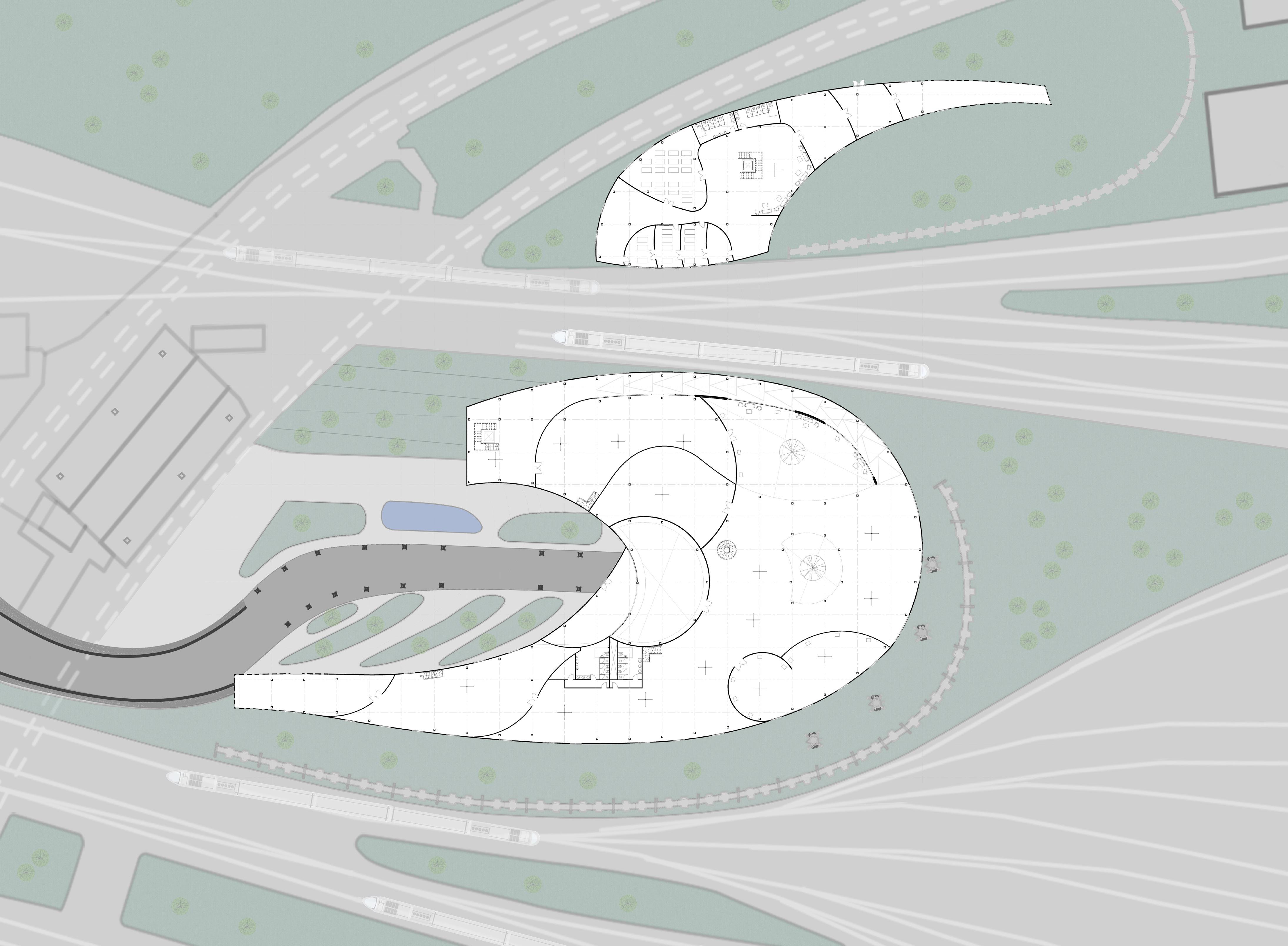
GROUND FLOOR FIRST FLOOR ENTRANCE ENTRANCE GABION WALL EXTERIOR WORKSHOP WORKSHOP ART GALLERY RECEPTION AREA TOWER DESIGN EXPERIENCE ROOM 1 DOUBLE HEIGHT REST AREA REST AREA WORKSHOP 1 2 3 4 STORAGE STORAGE MEETING SCULPTURE ROOM 1 STORAGE WORKSHOP 5 WORKSHOP STORAGE MEETING ROOM 2 ROOM 3 EXHIBITION SPACE COURTYARD AREA DIGITAL ART FASHION AREA EXPERIENCE ROOM 2 STORAGE CABLE CAR TOWER A A used Revit & Photoshop in the process
PROJECT PLANS
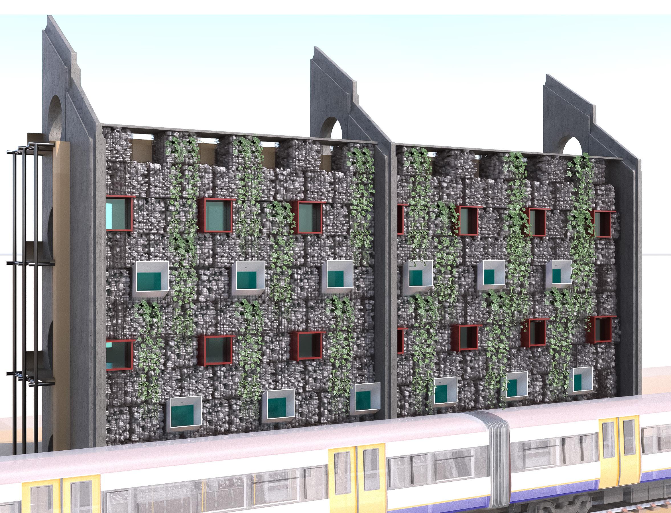
CONSTRUCTION APPLICATIONS

Gabion Walls
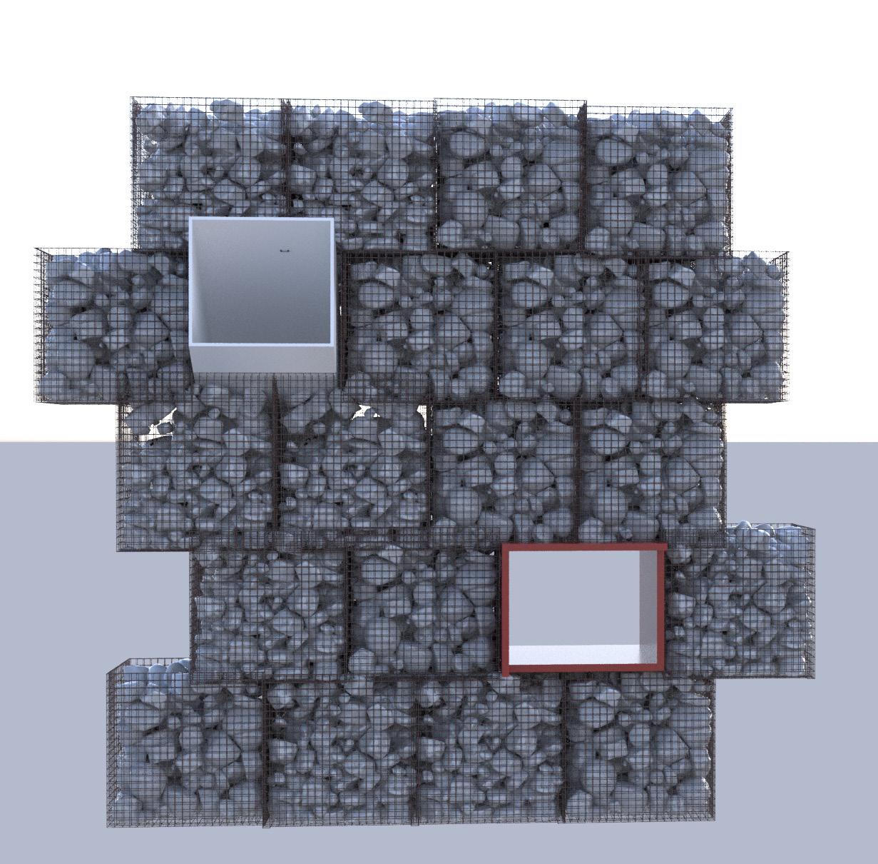
• Its purpose is to surround the site from the borders to act as a sustainable shield that will protect the building from surrounding railway harm.
Gabion wall is designed from recycled stone cages and rocks that can prevent pollution, noise coming from nearby railway to enter the site.
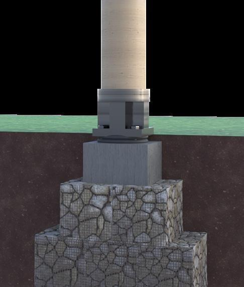
• In foundation (rubber bands)installed to prevent vibrations in gabion wall.
Construction considerations
Gabion wall is designed to be placed surrounding the site to protect the building from the nearby railway, which can cause pollution, noise and vibration.
Windows placed between gabions to allow daylight and sun to enter the site.
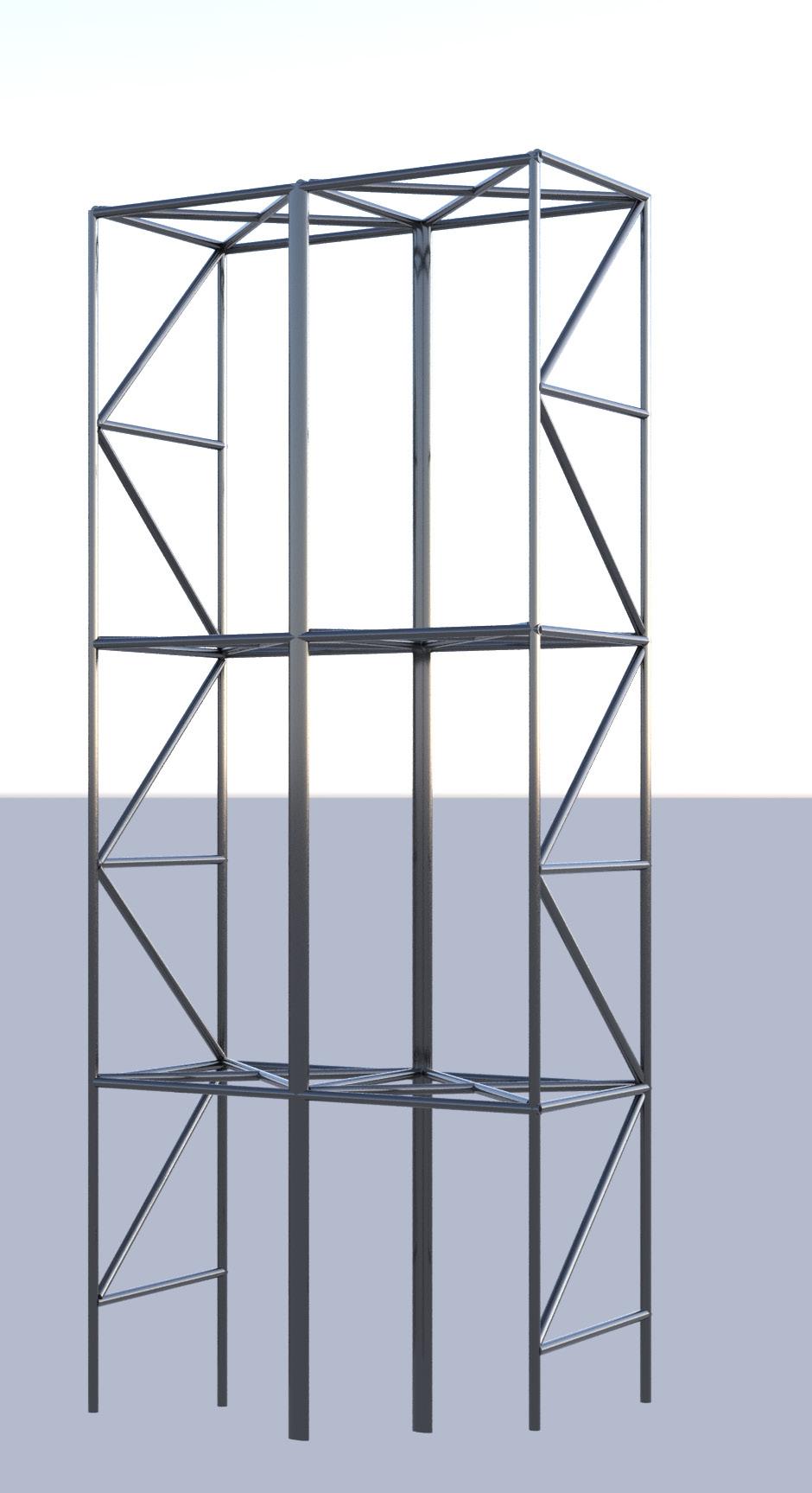
Steel frames and concrete columns to be placed behind gabion wall to support structure.
Pollution
Gabion rocks will prevent noise from passing through, plants on facade to filter the air pollution coming from railway.


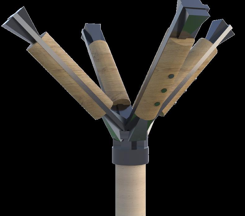
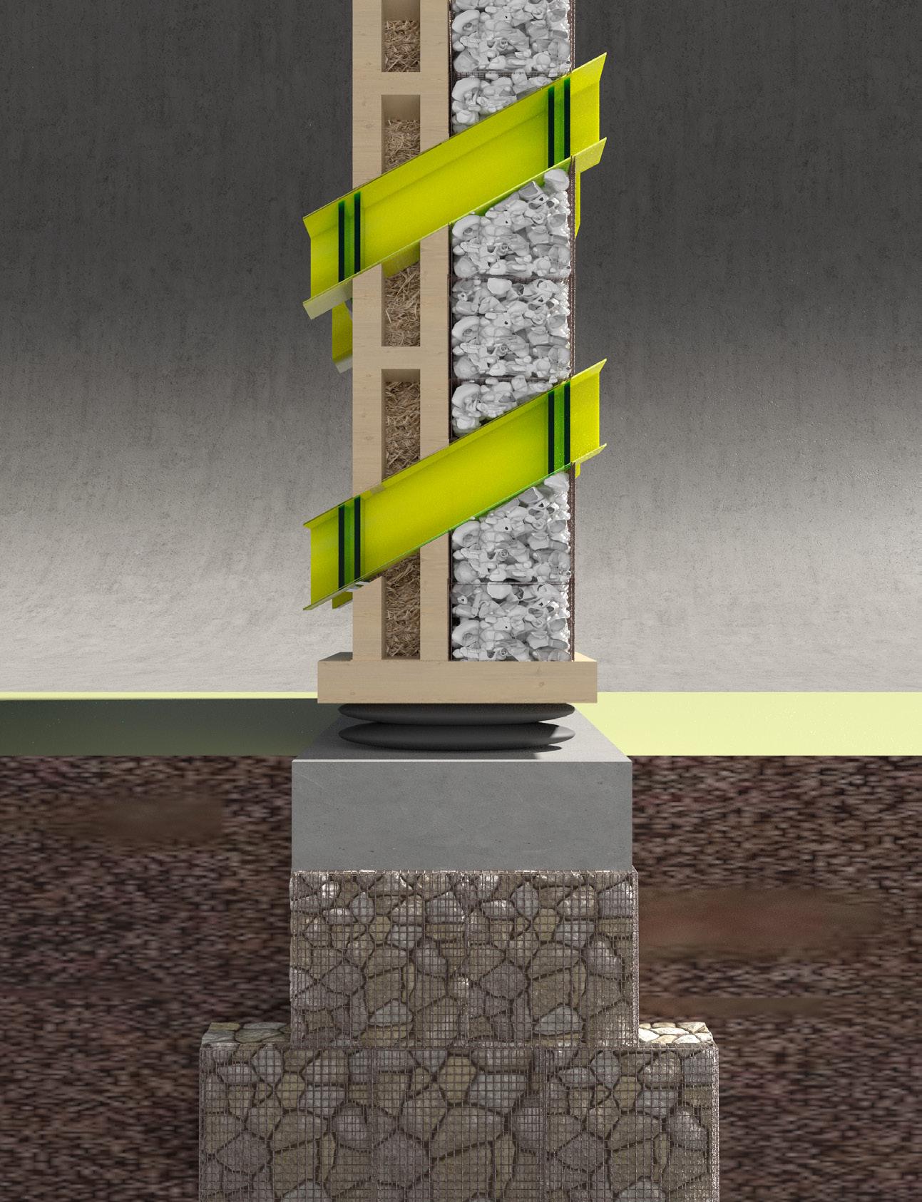
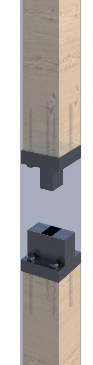
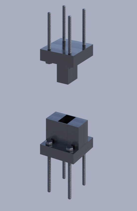
5 Earth Gabion foundation Anchor bolts Holding down bolt Concrete beam Steel connection Glulam column Rubber anti-vibration strips Steel strap Glulam column Steel sheet Galvanised steel column head Countersunk fixing Timber frame branch tapered 200x300x200mm diameter
1. Steel frame structure to support gabion back.
2. Straw insulator covered with 2 layers CLT.
3.Gabion walls (recycled steel cages and rocks).
4. Facade plants to collect dust.
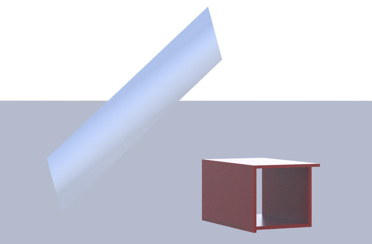
5. Double glazed 45 degree window.
6. Louvred window to protect from rainfall.
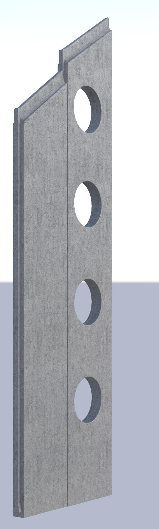
7. Concrete column (structure engineer to determine spacing between columns).
8. Roof story supported with steel rails (900mm height), contractor to ensure safety strategy for falling from heights risk.
2 7 6 5 4 1 8 3 9 Gabion wall idea
9. Railway overground train.
sketch
2 2 1 1 45 Noise Vibration Plants on facade To collect dust Opening in concrete column for floor slab to be placed. Ground 1st floor 1st floor 2nd floor 2nd floor Roof Roof Steel frames to support gabion back.
cages place on top of each other in a way to divide the load .
1 is rotated 45degrees
maximum sun to
the site. Window 2 louvred to
rain water from entering.
Gabion
Window
to allow
enter
prevent
used AuroCAD in the process
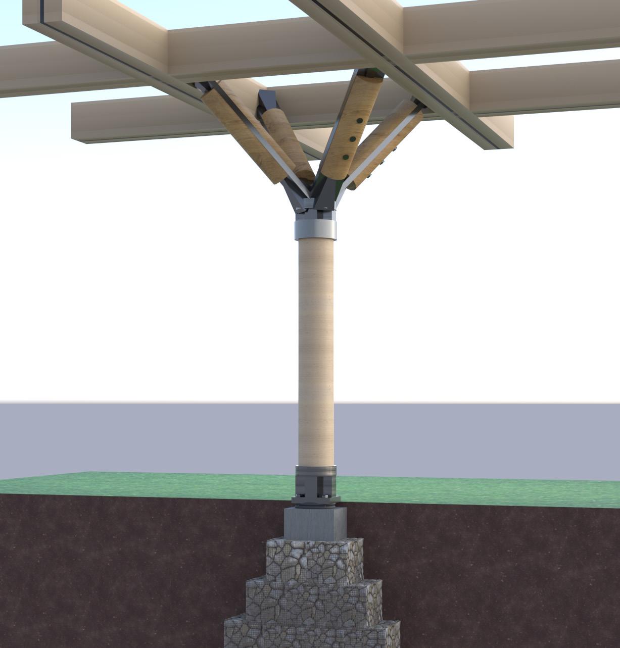
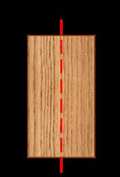
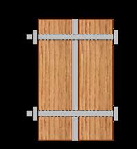

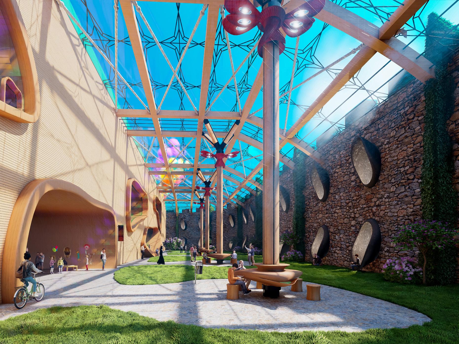
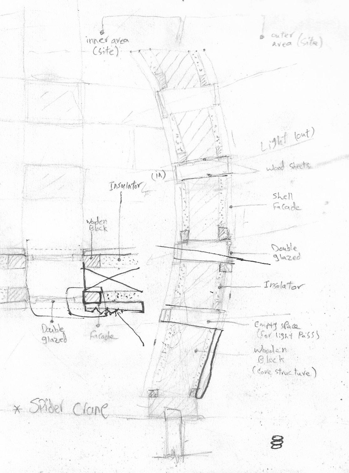
6 Earth Gabion foundation Anchor bolts Holding down bolt Concrete beam Steel column placed vertical each 5m Steel sheet Gabion column 500mm each Rubber anti-vibration strips Timber frames Straw blocks (insulation) 450 Concrete beam Gabion wall Gabion foundation Anti-vibration rubber strips Straw (insulator) Timber frames Double glazed window Timber louvres Thermal insulation Timber frames Glulam column type 1 Glulam Beam 500mm depth CLT 8 layers 400mm Triple glazed window Timber cladding Breather membrane Exterior wall and curtain wall Gallery facade material used is timber cladding with curtain wall and window openings in the desired areas. • Window are controlled using wooden louvres in rooms with oil paintings. Breathable control, thermal insulation and vapour control layers installed to exterior wall to control environment defects. Glulam beam Cut in half Steel plate placed in between Beam bolted from sides Gabion foundation Glulam column Column steel head Flitch beams Glulam column Threaded rod diameter 16mm Floor finish Wood skirting cover Wood skirting cover Steel connection (Plug connector) Glulam Column design used AuroCAD in the process
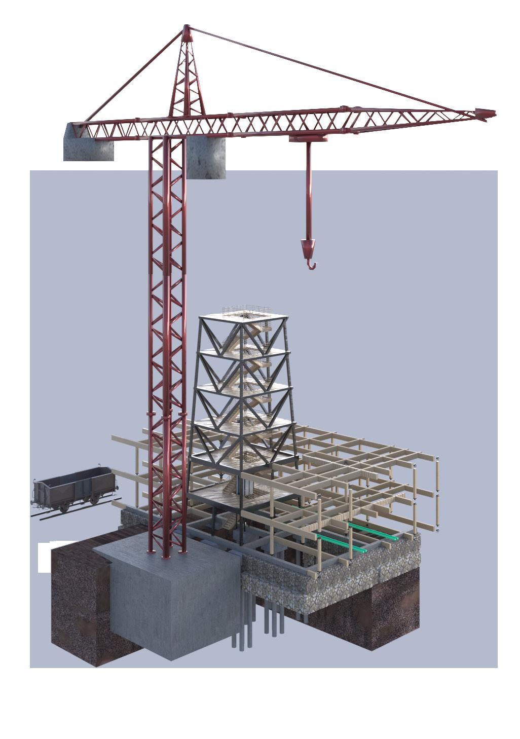
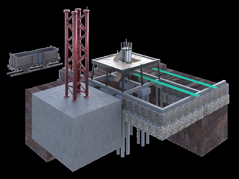
While installing tower crane element, spider crane will left elements for installation.
Contractor and safety engineers to ensure safe installation process.
HEALTH AND SAFETY
Risk of falling from heights when building and working with crane. Contractor to ensure safety strategy.
CLADDING & INSULATION SYSTEM
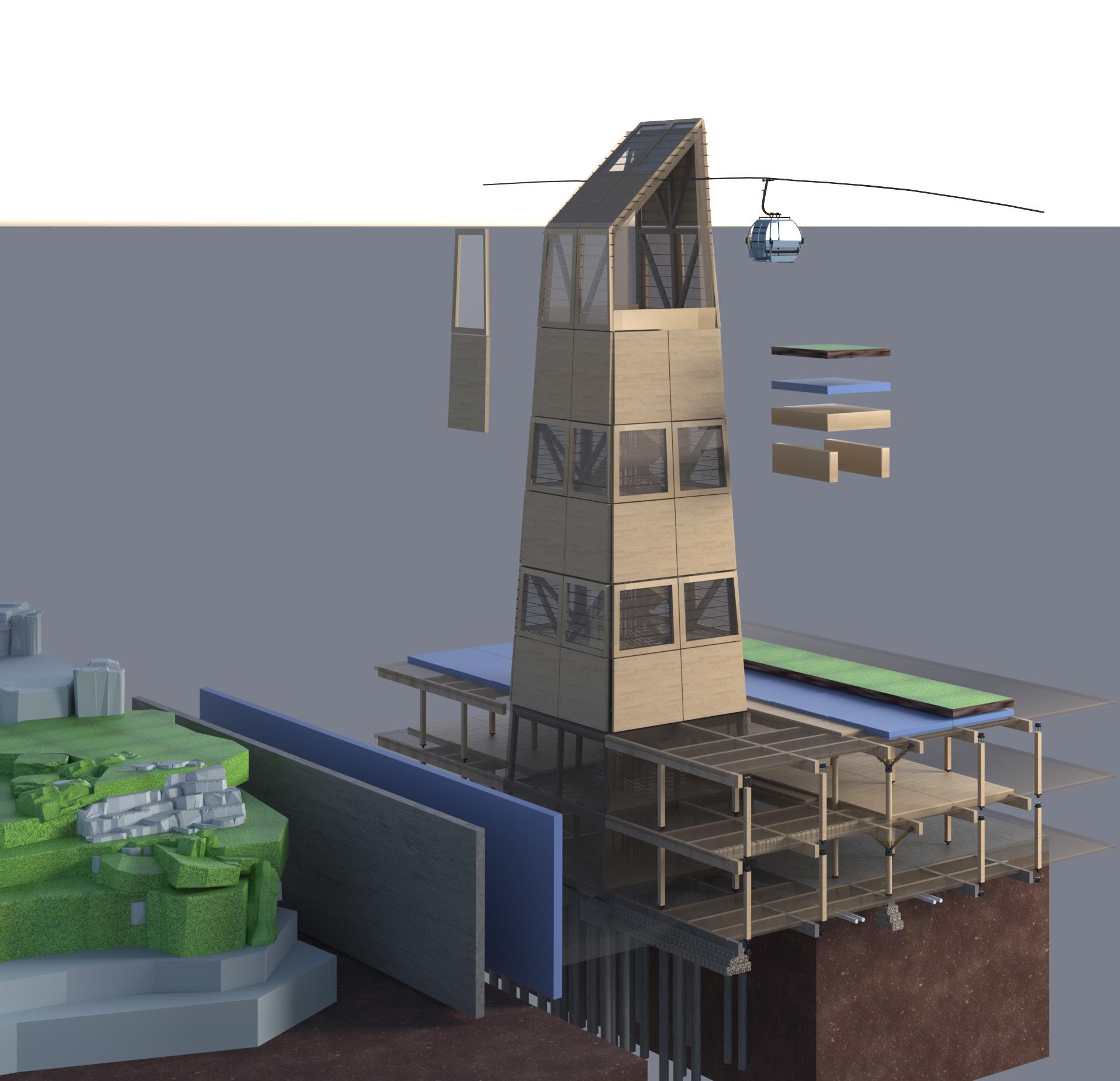
Cable car
Glulam beam(primary) Glulam beam(secondary) +20m
Glulam tree column
Staircase & lift
Timber frames
CLT flooring
Glulam column sets on RC slab with gabion wall foundation
Pile cap
9m
Glulam type 1 column
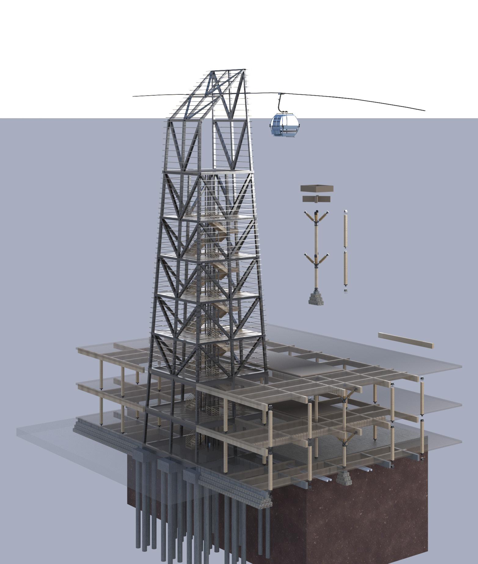
Glulam beam CLT Drainage below slab
RC piles 300mm diameter Soil
Timber framed double glazed window
CLT panel
Sloped roof to fall into guttering
Insulation
RC concrete wall
Green area (up hill)
Green roof Insulation and drainage layer
CLT 6 layers
Glulam beams
Glulam beam CLT
Drainage below slab Soil
7
crane elements
crane foundation TFL construction element delivery train
Tower
RC
used 3DsMax & Indesign in the process
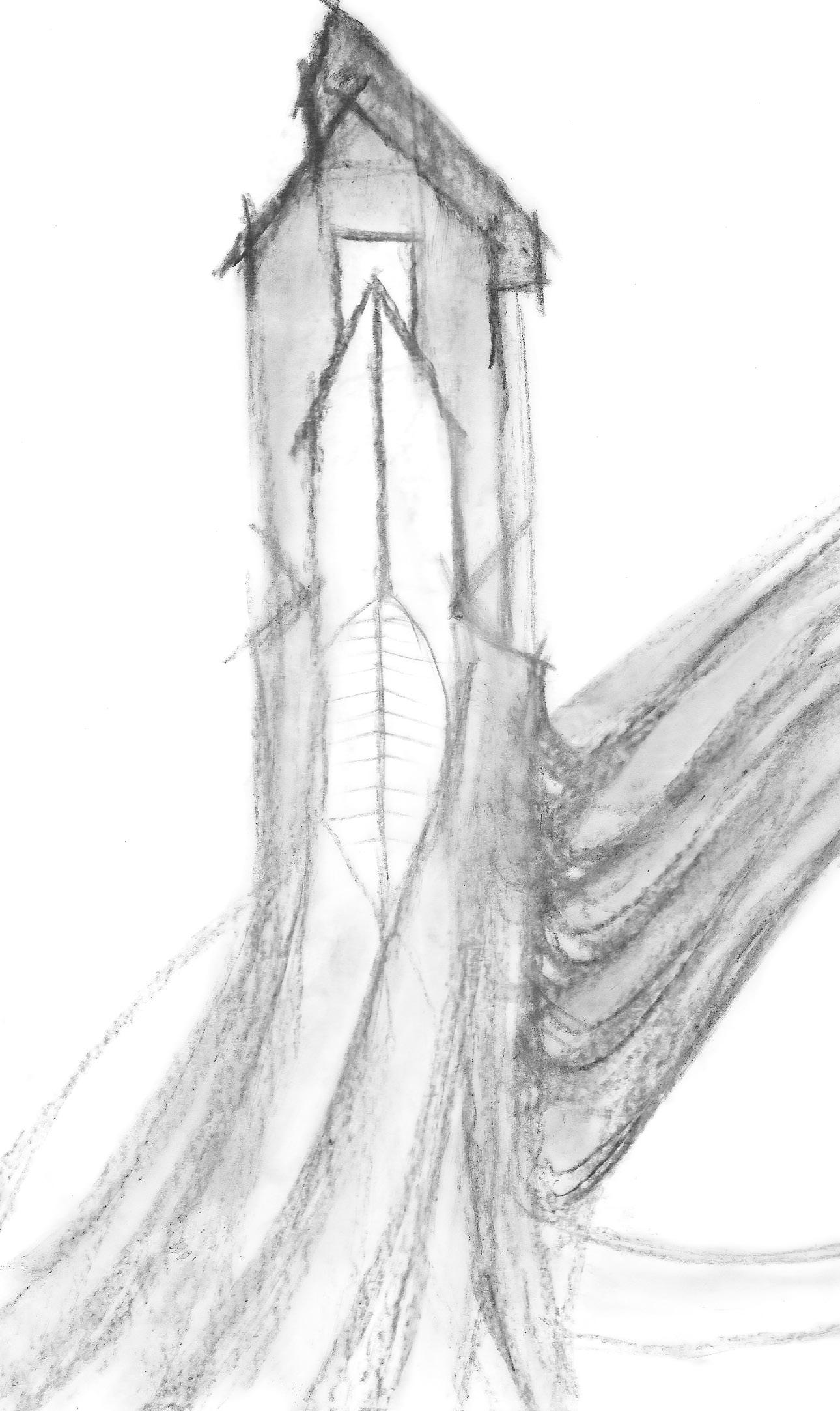
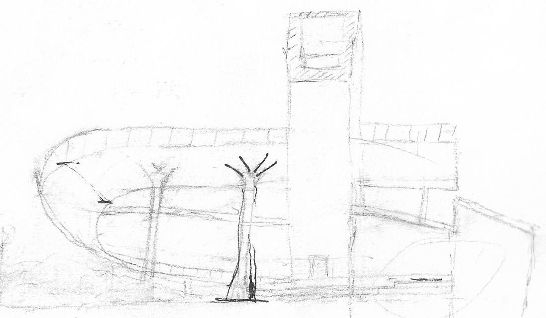
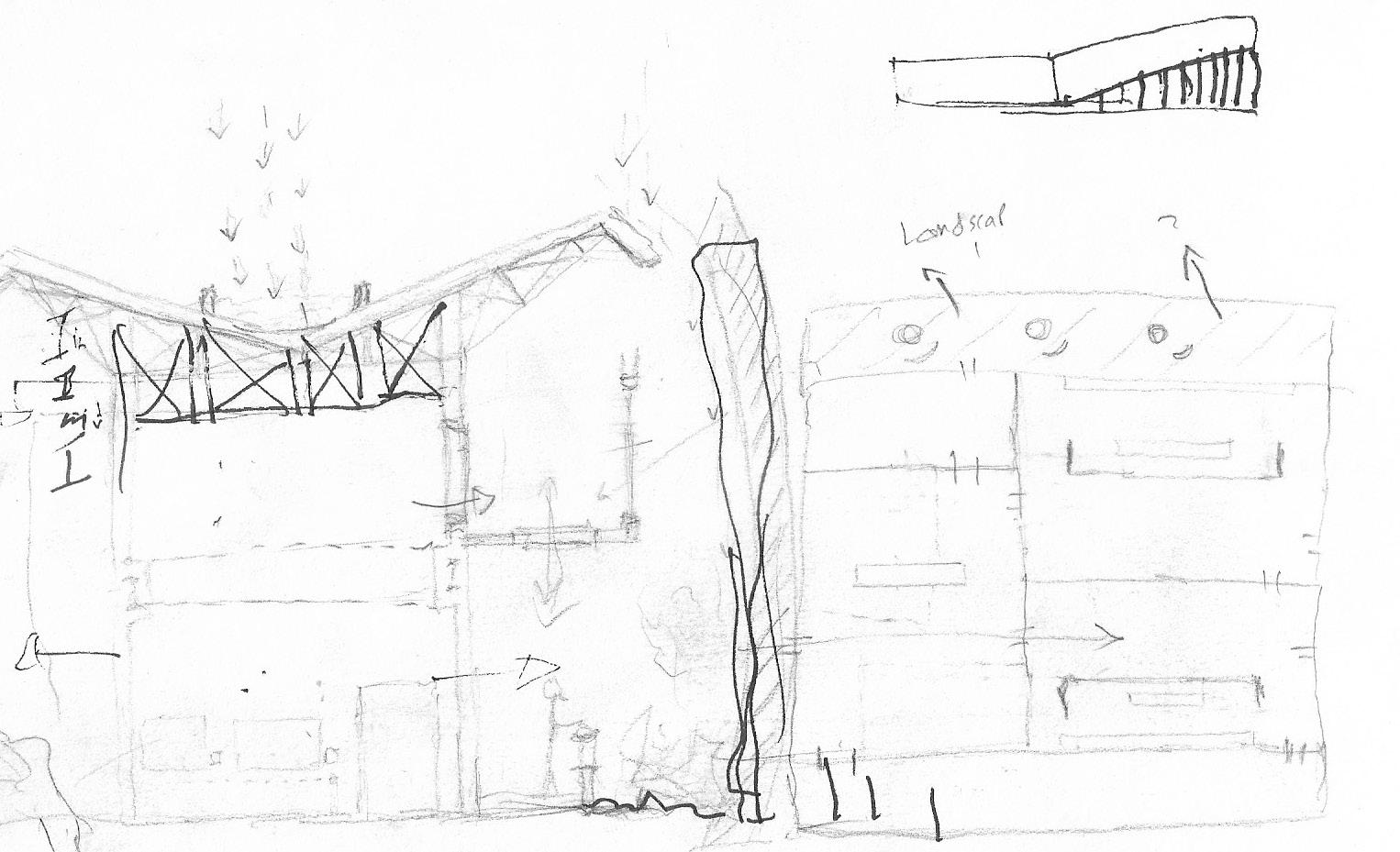
8 HAND SKETCHES & RENDERS used 3DsMax & Hand-sketch in the process
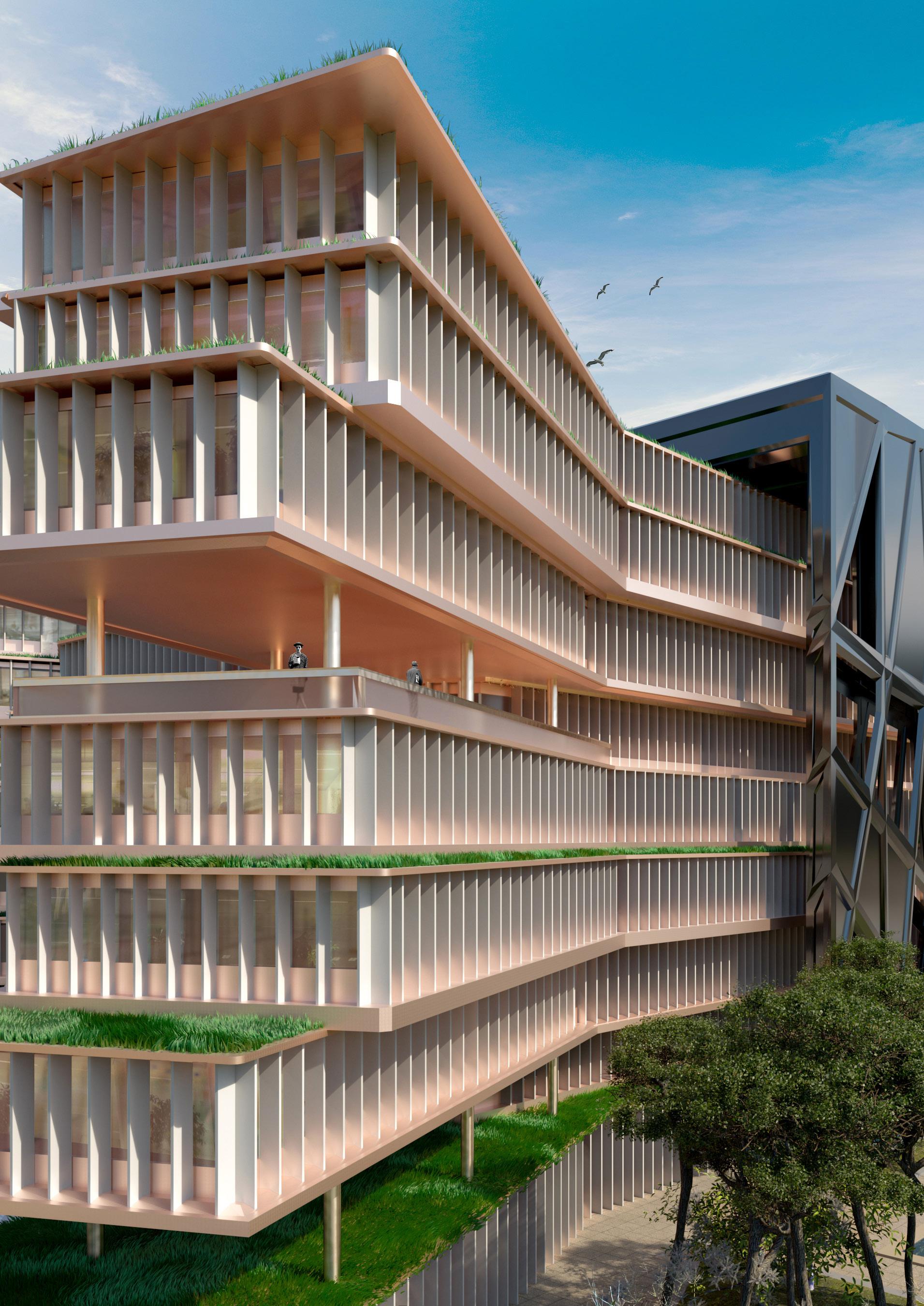
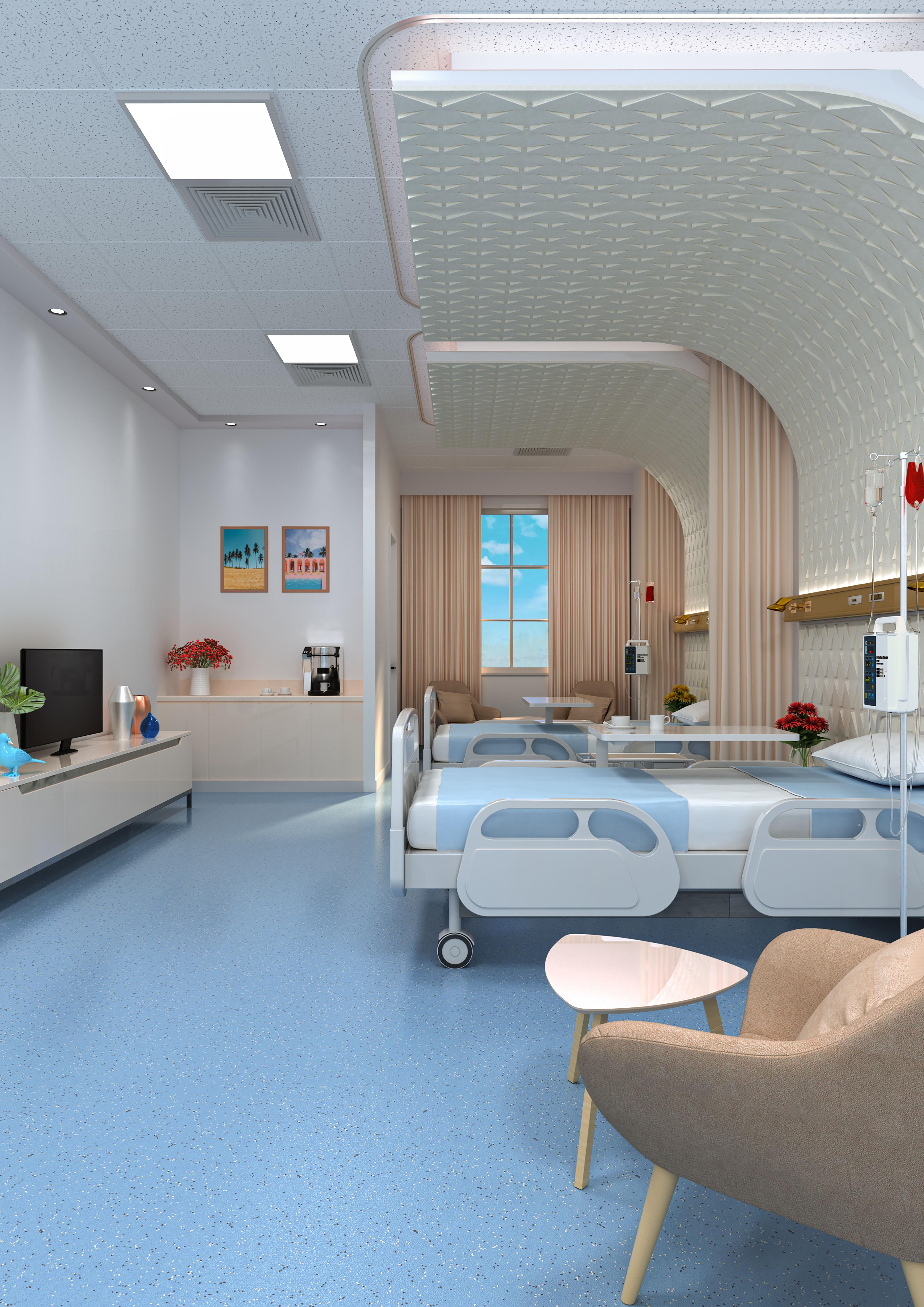
GENERAL HOSPITAL PROJECT
This area (Cairo, Egypt) lack health care facilities, in which the existed buildings were either too old or does not have the proper services and required departments.
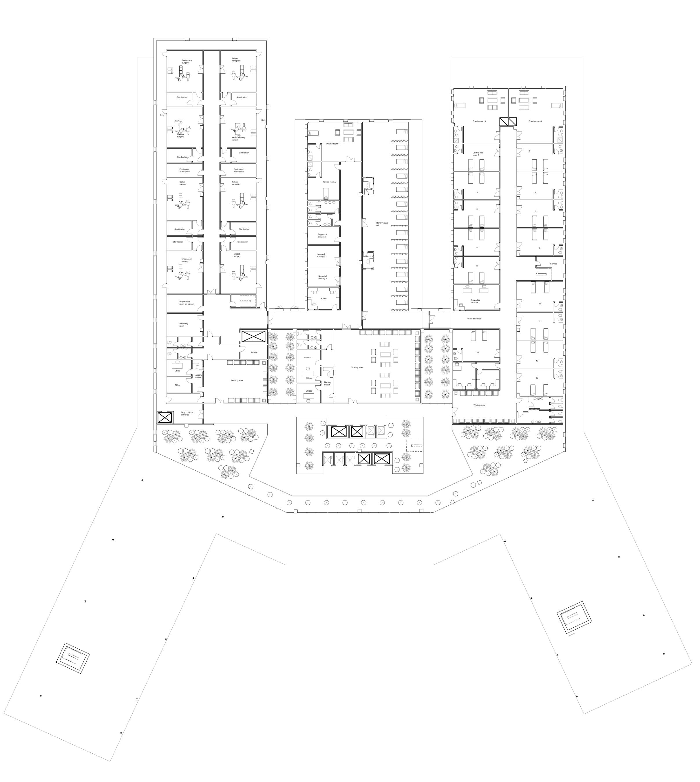
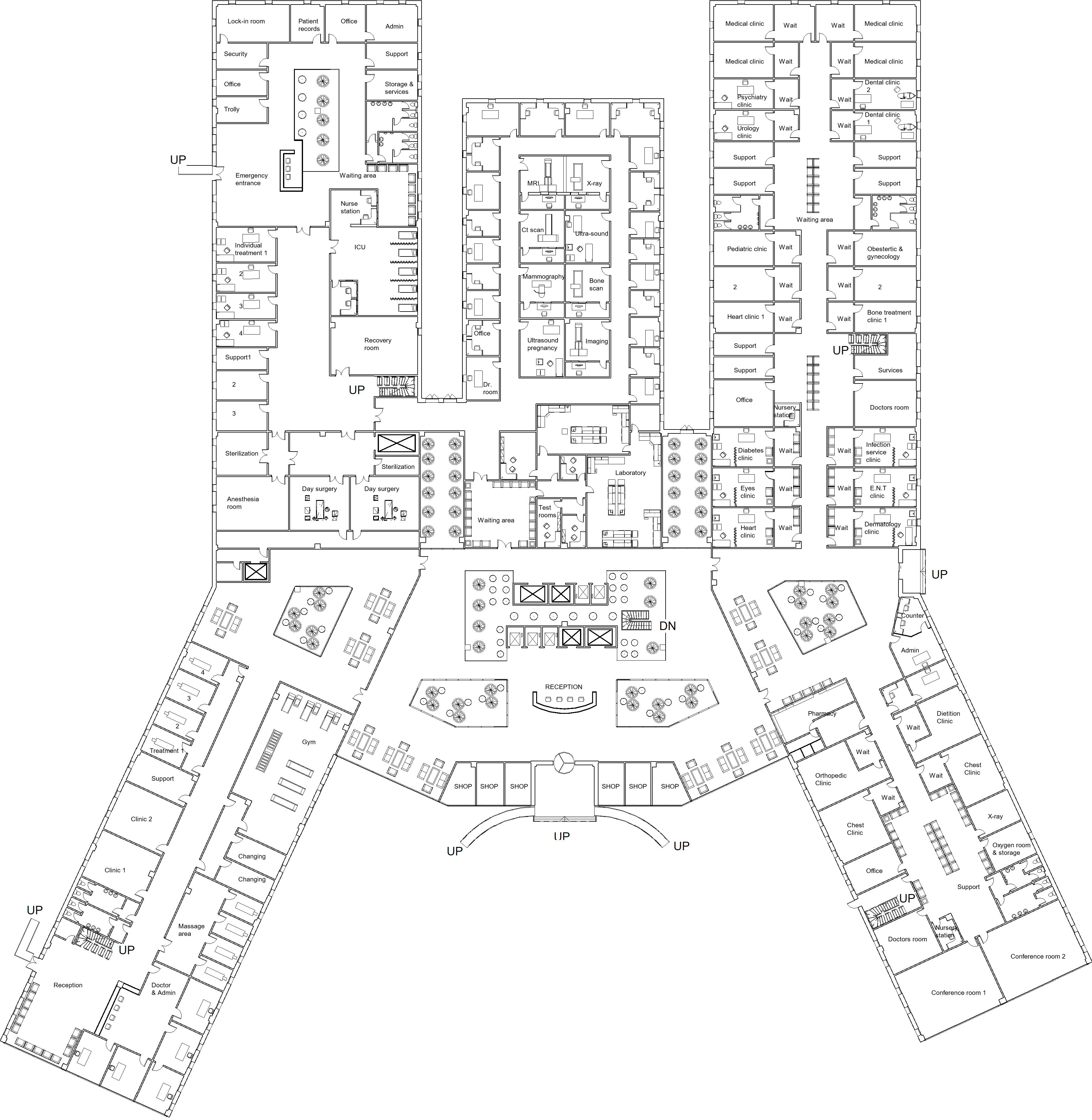
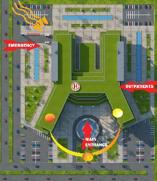
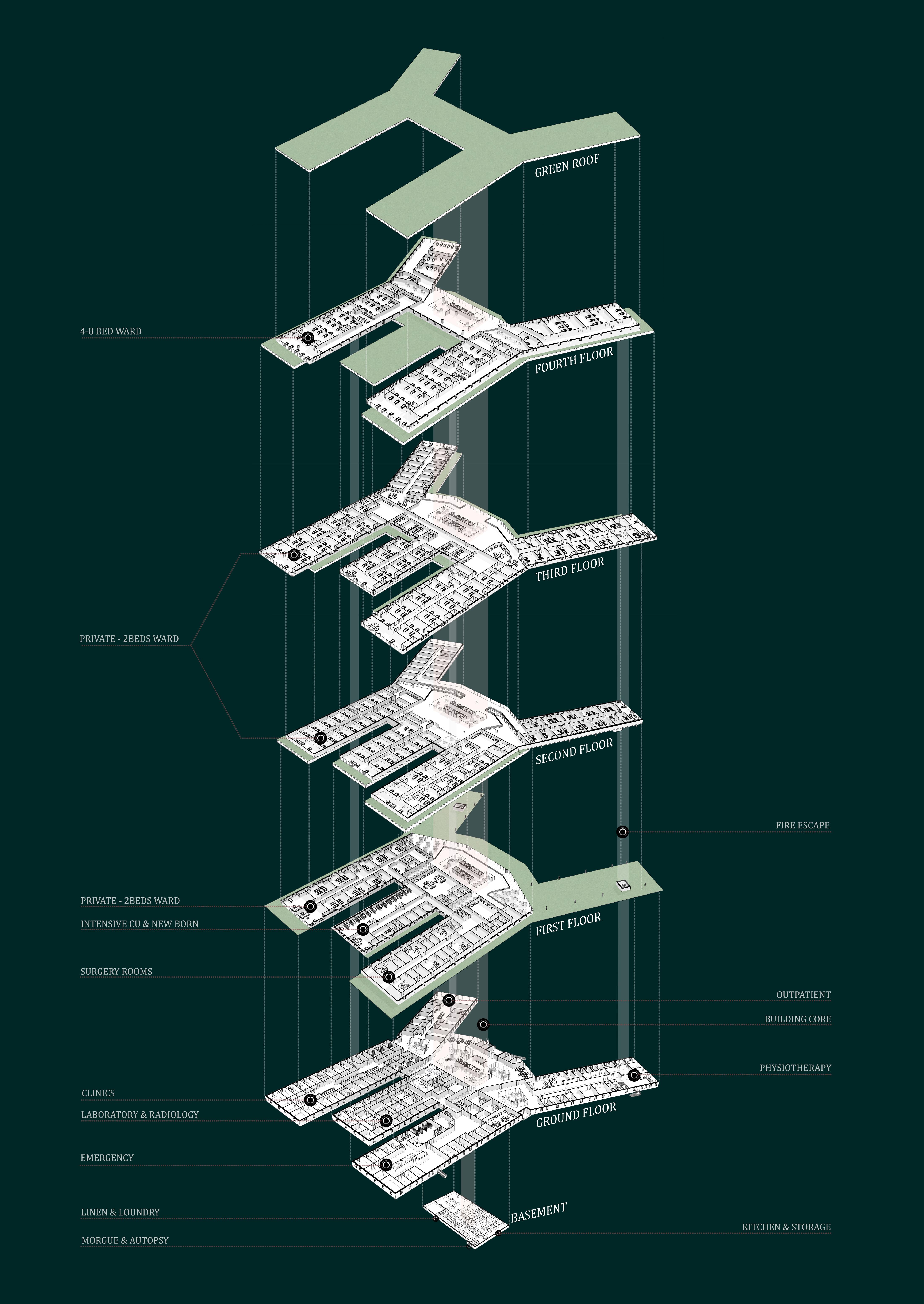
Form inspired by human body, heart is the core of the building, the arteries which is connected to the heart provide body parts with blood, considered as the hospital departments and wings. (Movement of blood represents circulation inside hospital).
Concrete construction is a good way to improve the function, value and whole life performance of the facility. Using RC columns dimensions between each is 12m maximum.
Waffle slab to support column with loads, and Hospital ceiling services can be managed through waffles spaces.
9
first floor plan floor plans & form generation used Revit in the process
master plan
10 used Revit in the process
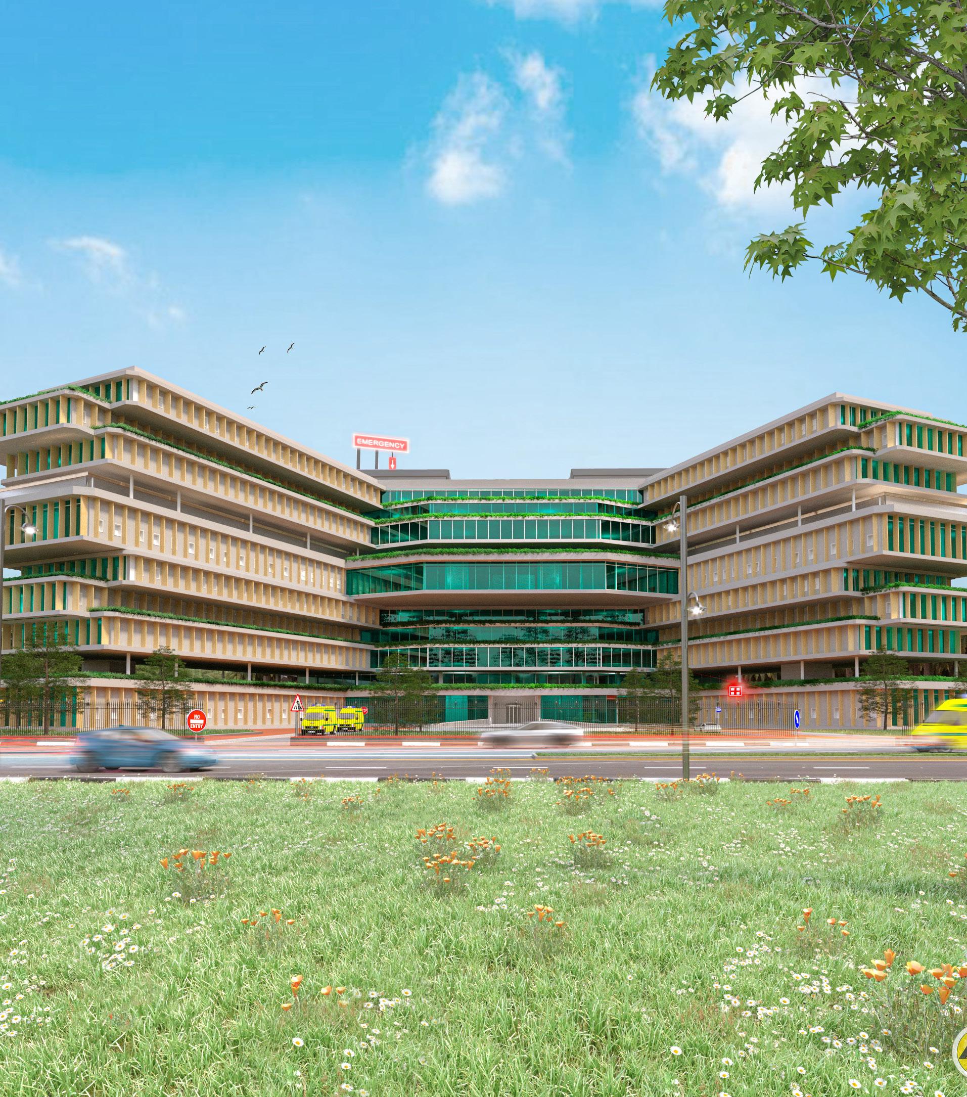
11 used 3DsMax in the process
12
13