9 minute read
The butterfly effect


Scott Jago, STS Marine Solutions Ltd, UK, outlines the root causes of LNG composite hose failures and the procedures to elimate this risk.
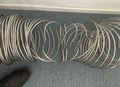
The discovery of metal deformed in such a distinctive way is becoming a common sight to the technical department of STS Marine Solutions Ltd (LNGSTS). For those that do not recognise what is being observed in Figure 1, it is a damaged internal reinforcement coil of an LNG composite hose that failed when used for an LNG ship-to-ship transfer operation.
It may be puzzling to the observer how it could possibly be manipulated, twisted, and contorted in such a distinctive way. Amongst the technical department of LNGSTS this has become known as the butterfly effect, due to the distinctive way the metal folds.


What is disconcerting is this is not a result of a hose pinch, crush, or a kink. But rather the result of unwanted conditions created inside the hose during the transfer process.
STS Marine Solutions Ltd has had a dedicated LNG department since 2005 and has operated underneath the brand name of LNGSTS. Over the last 16 years, the company has been aware of numerous similar hose failures throughout the industry. LNGSTS has consulted on a number of projects post failure, on process and procedures to help eliminate the risk and root causes of LNG hose damage.
To appreciate the forces involved in bending a wire into such shape, it is worthwhile considering that the internal and external wire helix of an offshore transfer hose are normally constructed out of an austenitic stainless steel with chrome, nickel, and molybdenum content – a high-grade stainless steel with superior strength and rigidity.
Such strength and rigidity are demonstrated when these hoses are subject to acceptance testing.

Figure 1. Aerial section of damaged hose.

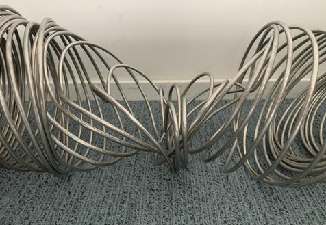
Figure 2. Cross section of damaged hose.
Figure 3. Internal helical wire interlock release.
Example of strength
An impact test was conducted on an 8 in. LNG composite STS hose, with an impact weight of 325 kg at a height of 1.5 m, and a 4-bar internal pressure. The inner and outer wire deformed only by 40 mm.
A crush test was conducted, with a crush weight of 7 t, on a 500 cm2 plate, and a 4-bar internal pressure. The inner and outer wire deformed only by 129 mm.
When considering the aforementioned tests, the mind can only wonder what forces were involved to distort the internal wire in the way that is shown (Figure 2). It may be an easy assumption to make that some catastrophic breakdown in process or serious malfunction may cause this, but the next section of the article will detail how only subtle errors can lead to this.
The butterfly deformation of the inner wire (i.e. the inward collapse of the wire from one side) is normally over a few windings of the coil – the buckled section is symmetrical from the most buckled middle wire. On top of the buckled geometry the wires tend to lean away from the buckled section’s centre.
Even the buckled crests do have a deformation component in an axial direction. Adjacent to the buckled wires, the inner wire is toppled. The outer wire is never indented or (significantly) increased in diameter. This rules out that the damage is caused by external forces.
The toppling of the wires is caused by an axial force, releasing the interlock of the inner and outer wires. Due to the geometry of the hose wall, the inner wire is restricted by the barrier (i.e. the fabric and film stacks) from moving in an axial direction. One point to bear in mind as the details for why toppling occurs, which is outlined next, is that as the internal pressure of the hose increases and the diameter of the outer wire and barrier increases, the reduction of interlocking strength of the inner wire occurs.
Root causes of failure
With all the failures LNGSTS has seen, it is always one of two known common root causes that are identified as the culprit of the damage. It either relates to the lack of detail within the procedures regarding the hose (i.e. purging procedures, liquid freeing, etc.) or the awareness of conditions during certain transfer criteria, and lack of mitigation measures that should be used to prevent damage within the hose.
These short sights in the finer details of hose procedures can lead to the following physical phenomena within the hose, both of which have the capability to damage the hose. Liquid LNG at temperature and pressure conditions close to its boiling point, suddenly gets a temperature or pressure belonging to the gas phase and evaporates quickly. The most relevant effects and phenomena relating to this which are to be concerned about is flash evaporation caused by pressure drops and condensation induced water hammer (CIWH). Although the term relates
to conditions more commonly found with steam/water systems, the effect can be the same with LNG. Rapid phase transition (RPT) of a relatively small volume of LNG close to the hose’s inner wall can cause such damage. Evaporation of the methane from the LNG changes the LNG’s composition locally (i.e. methane content drops with respect to the other alkanes).
For a stable and safe operation, the Leydenfrost temperature, hose wall temperature, and super heating limit should be in a particular order. When the LNG temperature increases too fast (e.g. flushing too much LNG through a relatively warm hose), the particular order of the three mentioned temperatures can change and in particular cases cause a rapid and unstable phase change of the LNG which manifests itself as a sudden local ‘explosion’ type pressure build-up that generates local high pressure.
Both similar in nature, these phenomena need to be avoided to ensure safe operation of a transfer hose. Though ‘sudden evaporation’ and RPT are acknowledged as different physical phenomena, it does not mean that they will occur (always) separately. There is evidence that they can occur simultaneously and/or after each other.
By far the most common culprit that LNGSTS has identified as the cause to these failures is the liquid freeing procedure of the hoses after a transfer operation has occurred. A common method of pressure and release using nitrogen is employed in the industry and is generally the accepted method.
The greatest dangers arise when this method is attempted on a hose which is still completely full of liquid. The hose is full of warming LNG, which is pressurised up using nitrogen usually between 4.5 bar - 5.5 bar. This addition of pressure will effectively calm the LNG and bring it well within its liquid phase. Releasing the pressure to try and evacuate the hose of liquid has the opposite effect, removing the pressure quickly brings the liquid into what should be a vapour phase. The results of this can bring large, localised pressure spikes within the hose, reducing the interlocking internal/external wire forces. Combined with large axial loads due to the flowrate of the liquid draining this can cause the toppling of the internal wires.
The second most common cause of failure is related to when flowrates for each transfer hose become lower than 50% of the hose’s maximum rated flowrate. This causes the inability of the hose to generate a natural back pressure within the hose and the vessel’s manifolds. This scenario can allow vapour to form within the hose due to the very low thermal throughput, and low liquid velocity allowing ambient heat to be absorbed.
When vapour is allowed to form in a hose, a known effect called CIWH can occur. These CIWH conditions are caused as follows:
Warm vapour is allowed to form within the hose, and this forms on the top of the flowing LNG. An indication of this can be lack of frosting of the top of the hose where the hose connects to the manifold. The warm vapour will normally cool and collapse and condense when in contact with the cold LNG. In addition, the colder liquid will create boil-off vapour when in contact with warmer areas of the hose.
The collapsing vapour volume will have to be replaced with liquid, and boil-off volume will have to create space by displacing liquid. This process is continuous in nature and can be a non-disruptive effect, a stable stratification can occur and a multiphase layer in equilibrium can form within in the hose. However, with slight pressure fluctuations, presence of LNG flow and the layout shape of the hose in an STS transfer, isolated pockets of vapour can occur. With an isolated pocket of vapour, the volume of vapour is more susceptible to pressure fluctuations within the pocket and the vapour can, in some circumstances, very rapidly collapse.
Condensing rapidly, the impact of the liquid racing to replace the collapsing vapour can cause a shock wave within the system. This shock wave is normally brief but violent and contains dispersed two-phase flow at high velocities, in excess of the hose’s rated flow which can consequently damage the hose. RPT can be present in these conditions also and is theorised to be active within the collapsing vapour pocket, causing the butterfly deformation.
In both mentioned instances, subtle changes and constraints to procedures can limit these effects to a safe level. This will prevent damage to the hose and ensure a safe, successful, and efficient transfer. Considering transfers can vary between different vessel types, different equipment, and different operational constraints, generic advice on procedural changes is not recommended. However, the technical team at LNGSTS is willing and capable to assist any concerned parties with system and procedural reviews.


• Reduce Number of Expansion Loops • Longer Piping Runs with Fewer Joints • Increased Support Spacing
• • Lower Maintenance Costs • Double-Wall Vacuum Insulated la
Piping
MOST COST EFFECTIVE WAY TO TRANSFER CRYOGENIC LIQIQUIDS WE OFFER TECHNICAL ASSISTANCE FOR YOUR PIPE SYSTEM DESIGN EM DESIGN
INNOVATION. QUALITY. SUPPORT. EXCELLENCE


