
24 minute read
Cutting The Cost Of Compliance


Dr. Ian Saratovsky, Gerald Hunt and Martin Dillon, Lhoist North America, suggest how cement producers could achieve the most operationally cost-effective dry sorbent injection (DSI) programme, whilst complying with stringent SO2, HCl and mercury (Hg) emissions limits.


The Portland cement (PC) manufacturing process often results in the emission of gaseous pollutants, including SO2, HCl, and mercury (Hg) released from heating of the raw materials as well as fi ring of solid fuels inside the kiln. Throughout the US and the world, PC production facilities are required to control their acid gas and mercury emissions due to limits dictated in their operating permits, consent decrees and/or other regulatory mandates. In the United States, the Clean Air Act has previously driven the acid gas emission control requirements; however, other regulations and limits have recently been passed, such as National Ambient Air Quality Standards (NAAQS) which drives increasingly more stringent limits on SO2 emissions.

Specifi c to PC manufacture in the US, the National Emission Standards for Hazardous Air Pollutants (NESHAP) provides numerical limits for the emissions of particulate matter (PM), hydrocarbons, dioxins/furans, mercury, and HCl. Dry sorbent injection (DSI) offers a cost-effective solution to comply with these regulatory requirements. During the DSI system design phase, careful attention must be paid to sorbent selection, sorbent application location, and sorbent distribution into the gas stream to maximise the DSI system performance. In this article, various critical aspects of system optimisation are discussed in order to achieve the lowest overall cost of compliance.
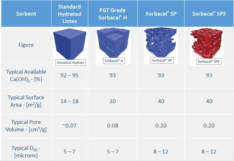
Figure 1. Physical and chemical properties of various hydrated lime sorbents.
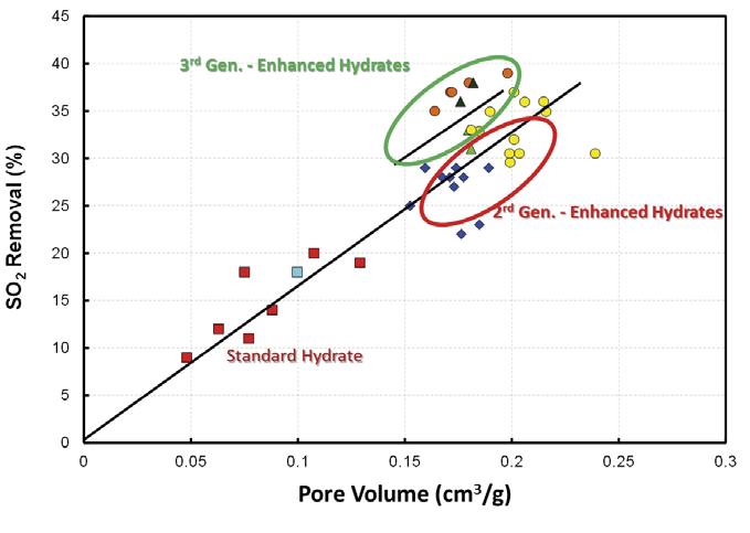
Figure 2. Impact of sorbent physical properties on SO2 capture. Pore volume and surface are the two key performance indicators for hydrated lime products.
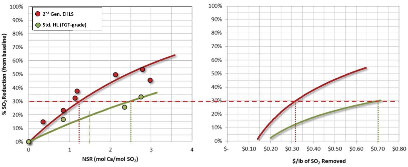
Figure 3. SO2 Reduction. Sorbacal SP (2nd generation EHLS) versus standard hydrate. Sorbacal SP (2nd Generation EHLS) resulted in a 54% reduction in sorbent usage over a standard hydrated lime. Background
System capital expenditure
DSI and activated carbon injection (ACI) are two mature and low capital technologies for acid gas control and vapour-phase mercury reduction, respectively. Both Hg and acid gas control sorbents have proven effective in a variety of industrial plants (i.e. utility, biomass, cement, waste incinerators, etc.) and have been used commercially in Europe and the United States for over 20 years. Trial results from a past HCl test campaign with CEMEX and Lhoist North America were detailed in a previous World Cement article.1 DSI and ACI injection systems usually consist of storage (either silo storage or bulk bag, i.e. ‘super sack’) after which product is metered into an air stream and conveyed via dilute-phase into the process gas stream, upstream of a particulate collection device. However, while often considered a low capital solution relative to other acid gas scrubbing technologies, the greatest capital associated with DSI and ACI is the initial equipment procurement and installation. For applications where mercury control is either intermittent or low injection rates are need, a blended hydrated lime (HL) and powdered activated carbon (PAC) sorbent allow for a single feed system to be used. For example, Lhoist’s blended HL-PAC product enables concurrent acid gas and Hg control using a single sorbent injection system (versus installing and maintaining two nearly identical systems) and injects the sorbents simultaneously as a pre-blended, homogeneous product. Lhoist produces customised enhanced hydrated lime (branded Sorbacal® SP and SPS) blends with brominated PAC in either bag or bulk, in 5% PAC (w/w) blend increments up to 30%.
Optimising operating expenditure
While a single, blended sorbent for Hg and acid gas can decrease overall system capital expenditure, careful attention should be paid to optimising the quantity of sorbent required to achieve compliance. DSI system design guidelines are discussed in detail elsewhere.3,4 The focus of this article is to provide sorbent selection and sorbent application guidelines to achieve the most operationally cost-effective DSI programme. To this end, prior to equipment design and selection phases (or after system commissioning, if this was overlooked during design), plants should consider: Optimal injection location (depends on target pollutants). Sorbent type. Sorbent application/distribution within the gas stream.
Sorbent trials with temporary DSI systems are highly recommended, before system design and selection phases or to evaluate alternative injection locations after a DSI system is installed. Sorbent trials should include measurement of dose-response (i.e. parametric) curves at several different locations within the plant to identify the most effi cient injection strategy.
DSI programme design considerations to minimise operating costs
Sorbent type – Standard hydrated lime?
Enhanced hydrated lime? Hydrated lime blended with powdered activated carbon (PAC) for simultaneous acid gas and Hg abatement? Injection location – Sorbent injection at kiln inlet? Gas conditioning tower (GCT) inlet?
GCT outlet? Baghouse inlet? ID fan inlet?
Abatement of HCl and SO2 often require different injection locations. Injection lance type and confi guration –
Standard pipe lances? Advanced sorbent distribution technologies? Static mixing lance designs? Dynamic mixing lance designs?
Differences in hydrated lime sorbents
Over the past 20 years, calcium-based sorbents have evolved, driven by the need to improve acid gas capture effi ciencies. Realisation of the importance of physical properties, such as particle size distribution (PSD), pore volume, and surface area led to the development of enhanced hydrated lime sorbents (EHLS) by engineering these properties to create more reactive hydrated lime sorbents. Sorbent physical properties directly impact material handling properties and acid gas removal performance, ultimately dictating annual operating expenditures. Figure 1 compares Lhoist’s commercially available hydrated lime sorbents and their typical properties. Lhoist’s EHLS products are branded Sorbacal, the 2nd generation product is
• CO2-neutral fuels in cement industry • direct heated by process air • full automated operation • low temperature drying • proven technology • low maintenance
www.stela.de
Sorbacal SP, and 3rd generation is Sorbacal SPS. Sorbacal SPS is a chemically-activated formulation of Sorbacal SP, specifi cally designed to provide enhanced acid gas capture performance. Figure 2 demonstrates the evolution of EHLS product physical properties and the resultant impact on SO2 capture effi ciencies. Pore volume (and indirectly, surface area) is the key performance driver for acid gas capture. While not critical to performance, sorbent particle size dictates material handling properties and removal effi ciencies in electrostatic precipitators and baghouse fi lters. Empirical data from the fi eld as well as laboratory fl ow testing have demonstrated that larger median particle diameters (i.e. D50) are recommended for optimum handling.2,6 Specifi cally, a 32% improvement in fl ow properties was demonstrated between particles with D50 = 2 µm and particles D50 = 11 µm.8,9 This is likely due to small particle sized hydrated lime sorbents being more cohesive than larger particles, and small particles can facilitate pluggage in the conveying system.8 Additionally, fi ne particle sized hydrated lime can become irreversibly lodged in baghouse fi lter bags and bin vents (i.e. ‘blinding’), and can result in premature wear and poor bag cleaning effi ciencies. Users should refer to their manufacturers’ design information regarding particle size and carefully weigh the impacts of introducing particles outside of the design range. Likewise, electrostatic precipitator (ESP) particulate capture effi ciencies decrease below approximately 6 µm and can result in increased particulate emissions.8,9 The key parameters to consider when choosing sorbents are pore volume, surface area, and median particle size (D50). Pore volume and surface area are the most critical performance drivers for acid gas capture. Particle size dictates material handling properties and removal effi ciencies in electrostatic precipitators and baghouse fi lters. Larger median particle sizes (≥ 6 µm) have been found to offer the best handling8 and particle capture results.8,9 It is noteworthy that ‘available Ca(OH)2’ impacts acid gas removal performance to a much lesser extent than surface area
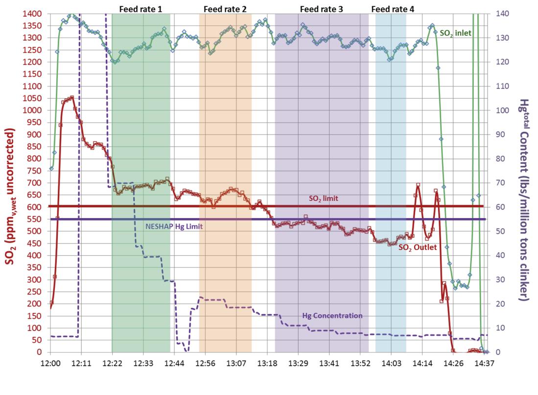
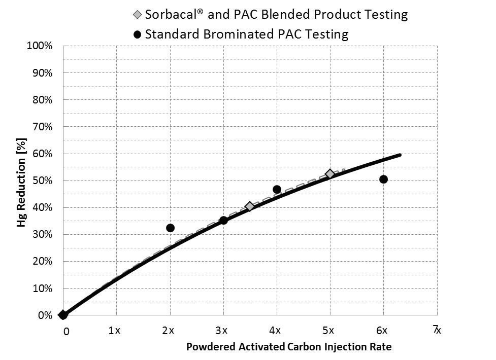
Figure 3. Physical and chemical properties of various hydrated lime sorbents. Simultaneous SO2 and Hg abatement with Sorbacal SP-PAC blended product. Acid gas emission measurements by FTIR were simultaneously conducted upstream of the injection lances (i.e. ‘SO2 inlet’ – green trace) and at the inlet to the baghouse fi lter (i.e. ‘SO2 outlet’ – red trace) to provide instantaneous performance even with variable process conditions. Hg was measured by CEMs at the stack (dashed purple trace). The relative quantity of PAC blended with Sorbacal can be custom-tailored (between 5% and 30%) to meet specifi c needs. Figure 4. Hg reduction with Sorbacal – PAC blended product compared with a standard brominated PAC. Blending PAC with Sorbacal hydrated lime products does not alter PAC performance.
and pore volume since sorbent utilisation rates (i.e. fraction of calcium ions consumed in the reaction) are seldom in excess of 50%.
Enhanced hydrated lime sorbents provide the following benefi ts versus standard hydrated lime due to their engineered and improved physical properties designed to enhance acid gas reactivity: Operating cost savings – EHLS typically reduce sorbent usage by 30 – 50% over standard hydrated lime sorbents, which results in a lower annual spend on sorbent. Less impact on ESP/BH fi lter – Lower sorbent dosage rates will result in less dust loading to particulate capture equipment. Less dust to an ESP may directly impact particulate collection effi ciency and for a BH fi lter this could impact bag cleaning cycle frequency.
Particle sizes play a critical role in ESP/BH operational effi ciencies. Respective equipment manufacturers should be consulted on particle size guidelines. Fuel and raw material fl exibility – If a lower cost fuel or raw material becomes available but results in an increased acid gas emissions, an
EHLS can provide additional fl exibility since it has the ability to achieve higher acid gas removal effi ciencies than standard hydrated limes, without having to modify the existing DSI system. Increased storage silo capacity – Lower sorbent consumption using EHLS results in more days of available storage in a fi xed silo volume. Hence, reducing sorbent consumption by 50% equates to doubling the silo storage capacity. One DSI system for acid gas and Hg control – EHLS blended with PAC are available and preclude the need for two separate systems.
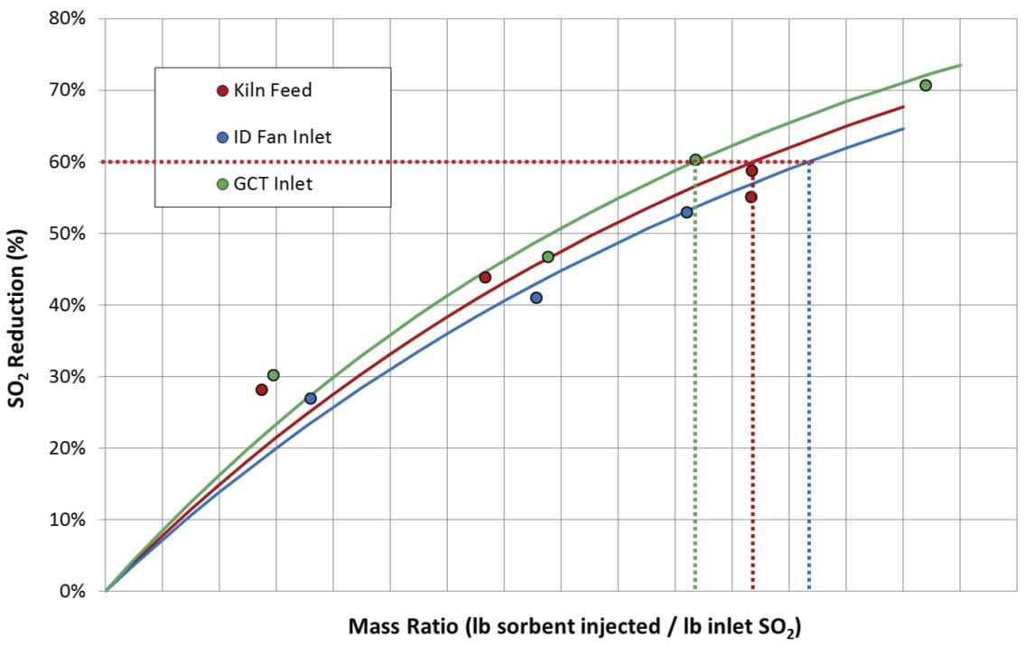
Figure 6. Comparison of DSI performance as a function of injection location. Sorbacal was injected at three locations: (1) with kiln feed, (2) at the gas cooling tower inlet, and (3) at the ID fan inlet. Note: these results do not always translate from plant to plant. It is critical to evaluate different injection locations at each plant to fi nd the optimal injection location.
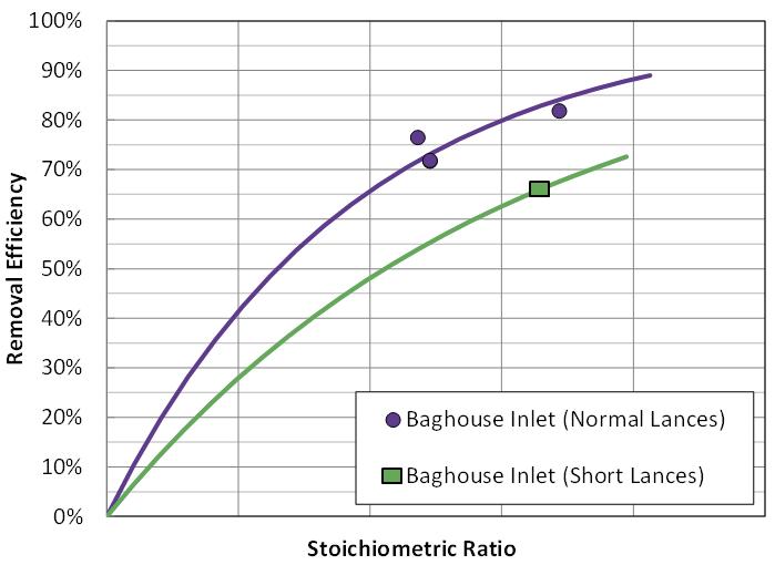
Figure 7. DSI performance with different injection lance confi gurations. CFD modelling is a useful tool to guide lance confi guration and design to maximise effi ciency and cost-effectiveness. Choosing the most cost-effective sorbent
The two most critical components to implementing a successful compliance strategy are: Proper sorbent selection. Sorbent distribution in the gas stream.
Assuming that the DSI system is properly designed, installed, and operated,2,6 choosing the most effective sorbent, injection location, and injection grid design are the next critical steps to optimising system cost-effectiveness. Although ELHS are typically more costly than standard sorbents on a delivered basis (i.e. U$/t), higher sorbent effi ciencies often result in overall lower total cost of ownership. For example, an EHLS may cost 30% more than a standard hydrated lime; however, EHLS usage rates are often 30 – 50% lower than the standard hydrated lime, resulting
in a net cost saving. Figure 3 illustrates relative SO2 capture performance of a standard hydrated lime sorbent and an EHLS at an industrial facility.
Requesting proposals from sorbent suppliers
Care should be taken when preparing sorbent requests for proposals (RFPs), since the quality specifi cation outlined in the the RFP could inadvertently result in the selection of an unsuitable or single source supplier. Identify potential sorbent suppliers and communicate with them to better understand the most critical sorbent attributes as well as the chemical and physical properties of the sorbents they offer. For example, not understanding that sorbent purity (i.e. ‘available Ca(OH)2’) is less critical than surface area, pore volume, and that large particles are superior to smaller particles may result in choosing a single supplier, which may not be the most cost-effective choice.
Sorbents blended with PAC
For simultaneous Hg and acid gas abatement, Lhoist’s Sorbacal acid gas sorbents can be blended with powdered activated carbon (PAC). Simultaneous capture of mercury and acid gases offers the advantage of requiring only one feed system to install and operate. For applications in which mercury control is either intermittent (i.e. when using certain raw materials) or only needed for low injection rates, a blended product can be advantageous. Lhoist’s blended product enables concurrent acid gas and Hg control using a single sorbent injection system (versus installing and maintaining two nearly identical pieces of equipment) and injects the sorbents simultaneously as a pre-blended homogeneous product.
Injection location and lance confi guration
Another critical aspect of the DSI process is choosing the best injection location and specifi c design of the injection grid. The injection location and grid design directly impact how the sorbent is introduced into the gas stream. Sorbent distribution and coverage in the gas stream dictate pollutant removal effi ciencies and resultant operating costs. A key question is where to locate the injector(s). The target pollutant(s) typically guide where to locate injection lances; however, it is recommended that each facility performs site-specifi c testing, especially for cement applications. It is recommended that several injection locations are evaluated during a trial, with a temporary DSI system. For example, SO2 capture by hydrated lime is typically favoured with injection at higher temperature, whereas, HCl capture tends to be favoured at cooler temperatures. Figure 6 illustrates relative SO2 abatement performance in a cement plant, with injection at the kiln feed, gas cooling tower inlet, and ID fan inlet. Figure 7 illustrates the impact of lance design on sorbent performance. Without a trial to determine the best injection location, incorrect injector location selection can result in higher usage rates and annual costs.
Once injection location is determined, injection grid design is the next key performance driver. Injection grid designs can be as simple as a single injection lance or as complicated as a multi-lance design with various penetration depths.
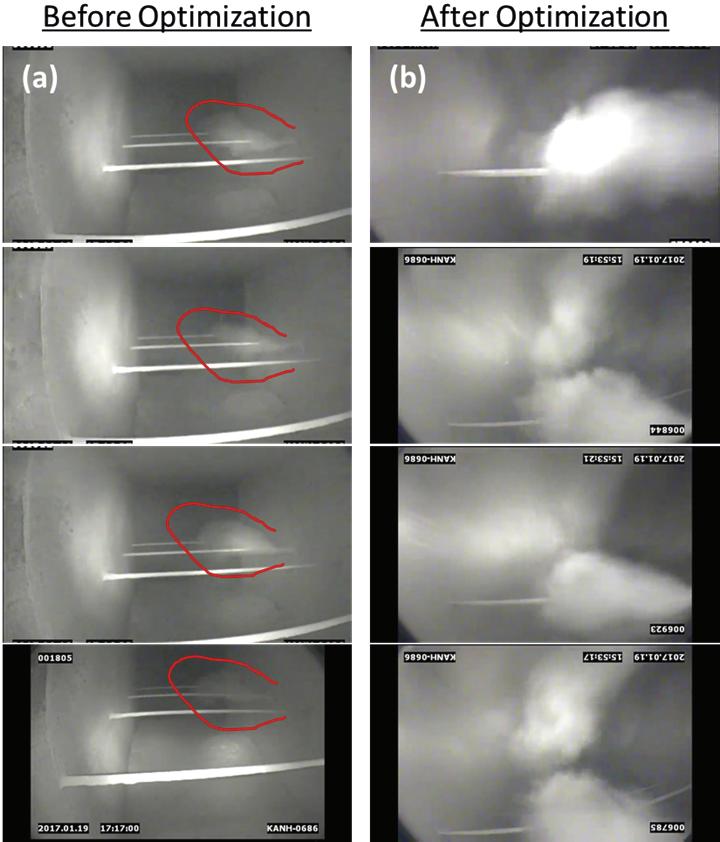
Figure 8. View of sorbent dispersion in process gas stream. Induct camera images of sorbent distribution at a cement plant. Images were recorded upstream of the injection lance(s), which were located between an electrostatic precipitator and baghouse. (a) Illustrates the poor-sorbent distribution with the original single-lance confi guration. The area in red highlights the white sorbent plume. (b) Illustrates the improved sorbent distribution with the addition of lance (for a total of six). Additionally, fl ow was balanced by modulating dampers at the baghouse clean air plenum. Originally, fl ow in this duct was highly stratifi ed (as verifi ed with Pitot tube measurements), and fl ow balancing and addition of lances resulted in a cloud of sorbent distributed across the duct.
Over the past few years new injection technologies have emerged, signifi cantly improving sorbent distribution within the gas stream, and reducing sorbent consumption. These systems can result in operating cost savings with a relatively quick return on investment. CFD modelling is a benefi cial tool to be used to guide injection grid design in order to optimise sorbent distribution. In-duct cameras can also be employed to visually inspect sorbent distribution following system installation to corroborate good distribution, and identify distribution ineffi ciencies. Figure 8 is a photograph taken with an in-duct camera inserted into the gas stream to evaluate sorbent dispersion during a full scale DSI fi eld trial.
Conclusions
Sorbent selection, proper location of injectors, and injector grid/lance design are the most critical parameters that determine overall DSI system effi ciency. Over the past two decades, enhanced hydrated lime sorbents (EHLS) have been specifi cally optimised for acid gas abatement applications. In the past, sorbent selection was driven by geologically-dictated hydrated lime purity (i.e. available Ca(OH)2). Today, sorbent purity has little impact on performance and sorbent performance is primarily driven by porosity (i.e. surface area and pore volume). Additionally, blended sorbents (PAC and EHLS in one sorbent) can reduce the system cost (i.e. only one injection system is needed). EHLS particle sizes have been optimised for superior material handling and particulate capture by baghouse fi lters and/or precipitators (i.e. larger particles are better). Locating injectors in a cement plant should be driven by data from trials with temporary DSI systems. Once injectors are located to maximise sorbent effi ciency, injection grid design should be guided by CFD modelling. Following system installation, in-duct cameras can be used to evaluate and tune sorbent injection grids to insure excellent distribution and coverage. Many of these critical parameters are easily evaluated during a short product trial and can result in signifi cant operating cost savings in the long run.
References
1. CIRO, W., & SEWELL, M., ‘HCl Control for MACT Compliance’,World Cement, April 2014, pp. 50 - 53 2. SEWELL, M., HUNT, G., ‘Optimizing Dry Sorbent Injection Technology’ World Cement, April 2015. 3. FILIPPELLI, G., ‘Living with Your DSI System’. CIBO Boiler Operations, Maintenance & Performance Conference, May 2016. 4. FOO, R., DICKERMAN, J., HUNT, J., JOHNSON, L., & HEISZWOLF, J., ‘ESP Compatible Calcium Sorbent for SO2 Capture at Great River Energy’s Stanton Station’, MEGA Symposium Conference Proceedings, August 2016.
5. HEISZWOLF, J., SEWELL, M., & HUNT, G., ‘Enhanced Hydrated Lime – A Simple Solution for Acid Gas Compliance’, IEEE-IAS/PCA, May 2017. 6. ‘Dry Sorbent Injection for Acid Gas Control: Process Chemistry, Waste Disposal and Plant Operational Impacts’, Institute of Clean Air Companies, July 2016. 7. WOLF, D.,’ Results of Hydrated Lime DSI Field Trial Tests for HCl Removal from Industrial Coal Fired Boilers’, CIBO Industrial Emissions Control Technology XII Conference, August 2014. 8. ZHIBIN, Z. & GUOQUAN, Z., ‘Investigations of the Collection Effi ciency of an Electrostatic Precipitator with Turbulent Effects’, Aerosol Sci. Technol. 1994, 20 (2), pp. 169 – 176. 9. LIN, G. Y., CHEN, T. M., & TSAI, C. J., ‘A Modifi ed Deutsch-Anderson Equation for Predicting the Nanoparticle Collection Effi ciency of Electrostatic Precipitators’, Aerosol Air Qual. Res. 2012, 12 (5), pp. 697 – 706.
About the authors
Dr. Ian Saratovsky is Director of Lhoist North America’s Flue Gas Treatment group. He holds a PhD in Inorganic Chemistry and Environmental Engineering from Northwestern University, an MBA from Northwestern University’s Kellogg School of Management, and was a Fellow at Oxford University in the UK for several years before entering the air pollution control industry. Since then, Ian has gained 13 years of experience in air pollution control, wastewater treatment, and industrial process optimisation. Much of his work has focused on developing new products for acid gas abatement and effi ciency improvements in solid fuel fi red-units.
Martin Dillon is the Manager of Flue Gas Treatment Applications with Lhoist North America. He holds a Bachelor of Science in Engineering from the University of Colorado at Boulder, a Masters in Engineering from Old Dominion University and is a registered Professional Engineer in Colorado. He has over 12 years of experience in the air pollution control industry and has worked on numerous multi-pollutant control demonstration projects for both electric utility and various industrial processes, including cement.
Gerald Hunt earned Bachelors and Masters Degrees in Chemical Engineering from the State University of New York at Buffalo. He is currently a Manager of Flue Gas Treatment Applications with Lhoist North America, Fort Worth, TX. His over a decade of experience in the air pollution control industry includes performing fi eld trials, proposal management, as well as process engineering in dry sorbent injection and wet fl ue gas desulfurisation technologies for the utility and industrial sectors.


CONSIDERING CONSIDERING CARBON CARBON CAPTURE AND CAPTURE AND UTILISATION UTILISATION


Dr Paula Carey, Carbon8 Systems, describes how the process of carbonation could help to reduce the cement industry’s large-scale CO2 emissions.

There is no doubt that carbon capture and storage (CCS) is one of the most important strategies that needs to be implemented in order to deal with large scale industry emissions.
The cement industry, responsible for as much as 8% of global CO2 emissions is, however, in a diffi cult position compared with most other large-scale CO2 emitters due to the locations of cement plants.
These are commonly isolated from other industries and are therefore distant from evolving CO2 clusters such as the Port of Rotterdam or Teesside, where plans are progressing to build the infrastructure to store captured CO2 in geological locations.

The cement industry is therefore having to consider a wider range of solutions to reduce its high carbon footprint, such as the use of RDF (Refuse Derived Fuel) rather than fossil fuels or using a range of SCMs (Supplementary Cementitious Materials). The industry has come a long way in recent years, reducing its carbon footprint from nearly 1 t of CO2 for every ton of cement produced to around 650 kg/t. There are limits to the amounts of SCMs that can be used without sacrifi cing cement quality, and the use of RDF results in an increase in the amount of by-pass dust that needs to be removed because of chlorides within it.
Therefore, across the world, the cement industry is embracing both types of carbon capture technologies – capturing CO2 from the cement plant fl ue stacks and also supporting the development of technologies that are using captured CO2 to make useful products. The industry has recognised that a portfolio of carbon capture and utilisation technologies are required to deal with the large volumes of CO2 that they are emitting. Carbon dioxide is being used to manufacture fuel, plastics, methanol, or urea as precursors to a range of other chemicals, with a view to replacing the chemicals derived from fossil fuels. Some of these technologies are already commercial but most are still at a pilot stage and are heavily subsidised by government research grants. The manufacture of fuels and other chemicals is energy-intensive, with CO2 remaining ‘captured’ for mere weeks in fuel, unless used for energy storage, or months and years in the case of plastics and chemicals. Because these technologies are energy intensive, they require large quantities of renewable energy to ensure they remain carbon negative. In contrast, the conversion of CO2 into carbonates, termed ‘mineralisation’ or ‘carbonation’, is an exothermic process – energy is created as opposed to consumed, and the CO2 is locked away permanently in normal use.
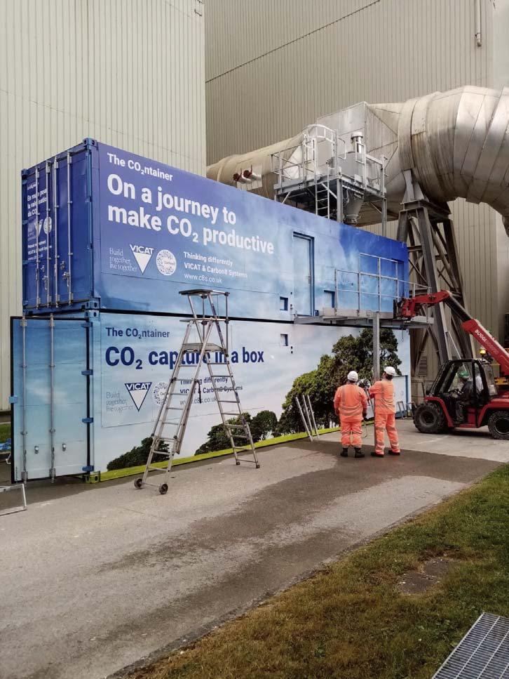
The CO2ntainers soon to enter operation at the Vicat cement works in Montalieu, France. Accelerated carbonation technology
Carbonation is a natural process in which CO2 is absorbed from the atmosphere over a period of several years in the case of concrete, or millennia in terms of rocks and the geological process of weathering, principally because the concentration of CO2 in the atmosphere is below 0.045%. Carbon dioxide reacts with calcium and magnesium silicates in cement within concrete, or in basic and ultrabasic rocks to form carbonates.
Carbon8 Systems developed Accelerated Carbonation Technology (ACT) as a treatment for contaminated soils and hazardous industrial thermal residues, including cement residues using CO2. The Carbon8 Systems business model is largely based on the high disposal costs for these residues and their valorisation through the manufacture of products such as
lightweight aggregates for the construction industry.
CO2 reacts with calcium silicates in cement in the presence of water before they have the chance to hydrate, forming calcium carbonate and a de-calcifi ed silicate. This reaction reduces the pH of the system and chemically and physically binds heavy metal contamination. Many industrial thermal residues, such as steel slags, fl y ash, incinerator bottom ash, or cement by-pass dusts, also contain calcium silicates as well as calcium oxides, which will rapidly react with CO2 if the conditions are controlled.
Because carbonation can reduce the hazardous nature of these residues, and products such as aggregates can be manufactured using the process, companies producing these residues can save on their disposal costs, permanently capture CO2, and have a product for sale in the construction market.
The mineralisation landscape
Carbon8 Systems is one of several companies that has developed an accelerated form of carbonation where the reaction takes place in minutes or hours.
CarbonCure is probably the most well-known innovator in the fi eld of mineralisation, using the delivery of carbon dioxide to green concrete to enhance the hydration of cement through the formation of small crystals of carbonate, on which hydrates can nucleate. Many ready-mix companies in the US are adopting their technology, delivering CO2 to the concrete as it is being poured, saving on the amount of cement required as well as directly turning a small amount of CO2 into carbonate.
Several companies (e.g. Orbix in Belgium and Carbicrete in Canada) are carbonating blocks made from steel slag. Other companies have developed low carbon cements which harden through carbonation, rather than or in addition to normal hydration, including Solidia and Heidelberg. A considerable amount of research and a number of pilot studies are looking at the carbonation of fi nes produced by the crushing of construction and demolition waste (CDW). This is a very variable but abundant waste stream which is being turned into SCMs or fi ne aggregate for use in concrete.
Industrial application of ACT
Carbon8 Systems’ technology has been licensed in the UK for the treatment of Air Pollution Control Residues from ‘Energy from Waste’ plants, and there are currently three fully operational plants treating up to 120 000 t of APCr a year. These plants use pure CO2 captured from fertiliser manufacture, for example, which is transported to site in a liquefi ed form in a tanker. The cost of pure CO2, which is commonly destined for the food and drinks industry, and supply issues made it an obvious choice for Carbon8 Systems to develop a process to capture CO2 directly from the fl ue stack of a cement works or Energy from Waste plant.
In 2018, the company was awarded a grant by the Ontario Centre of Excellence Solutions 2030 competition, which allowed the company to undertake the fi rst industrial-scale demonstration of direct fl ue gas capture of CO2, using its patented ACT process to carbonate cement by-pass dust at a CRH cement works in Mississauga, Ontario. The system was designed to be readily transportable, plug-and-play, and with a capacity that matched the amount of residue generated by the site.
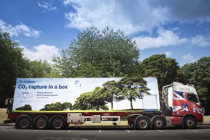
Enabling ‘carbon capture in a box’, the ‘CO2ntainer’ consists of two 40 ft shipping containers which connect directly into a plant’s fl ue stack.
Based on the success of this project, a further demonstration plant was installed at the Hanson cement works at Ketton in the UK. Partially funded by InnovateUK, the UK Government’s innovation agency, the company was able to design a more fully instrumented and automated plant for full commercial applications.
In July 2020, the fi rst fully commercial installation of the CO2ntainer, with the Vicat Group, was announced. The CO2ntainer has now been installed at the Vicat cement works in Montalieu, near Lyons, and will enter commercial operation later this year.
In its fi rst phase of operation, Carbon8 Systems’ CO2ntainer will process and convert up to 12 000 t of cement by-pass dust into aggregates that Vicat can commercially repurpose in various applications, for instance, in lightweight concrete blocks.
As well as the global cement industry, Carbon8 Systems’ ACT solution can be used in other industrial sectors, for example in power generation (Energy from Waste), the steel industry, and the paper industry – sectors where waste residue disposal is increasingly expensive and CO2 emissions need to be reduced as part of the transition to Net Zero by 2050. By utilising the waste at the source and onsite, companies using ACT will reduce the amount of waste going to landfi ll, thus further reducing the environmental impact of their operations.
About the author
Dr Paula Carey is the co-founder and Technical Director of Carbon8 Systems. Paula has been working on the development of accelerated carbonation for more than 20 years, and has an international reputation in the carbon capture sector, particularly regarding mineralisation.


