
8 minute read
Enhanced by automation


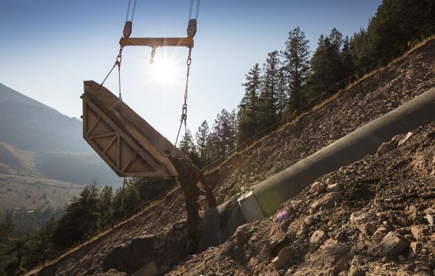
Figure 3. Transport of bulk material for filling of the trenches.
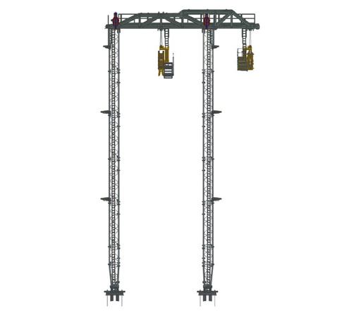
Figure 4. Tower structure of the new Dual Cable Crane System. for the full construction of the pipeline. Separately controlled lifting systems of the crane unit make it possible to lay pipes in inclined positions, and to position pipes in the best possible way to allow for welding, sandblasting, coating, and subsequent transport and unloading of sandbags and padding material effortlessly utilising special containers.
New technology The unique Dual Cable Crane System, engineered, manufactured, and erected by LCS combines a material ropeway with a lifting capacity of 16 metric t for line 1 and a personnel transportation system for line 2. Furthermore, the personnel transportation option line 2 has a lifting capacity of 5 metric t. By the use of two cable crane systems suspended from one portal frame at each tower location, the impact on the environment is diminished. With this portal frame construction, no longitudinal guy ropes at each tower location are required. All the advantages of the Dual Cable Crane System decrease installation times due to a reduction of required foundations and anchorage points.
The personnel transportation option adds various benefits whereby the construction time can be minimised significantly. While line 1 is occupied with lifting heavy loads and holding the pipe in place for pipe fitting, fixing of welding clamps and welding the first layers of the new pipe section, line 2 can still operate for the transportation of staff and various accessories and tools. Furthermore, with this system less helicopter transports are required for personnel which is always critical due to unexpected changes in the weather pattern. Another feature of the Dual Cable Crane System is the possibility to quickly evacuate workers in emergency situations regardless of any environmental conditions.
Case study: pipeline project in Canada For a project in Canada the new Dual Cable Crane System is currently under erection for the construction of a pipeline in up to 35˚ steep terrain. The pipeline with a length of 670 km and a pipe diameter of 48 in. is being installed through Western Canada. The installed system comprises a 16 metric t ropeway system for the transportation of pipes and various construction materials and a 5 metric t cable crane system equipped with a gondola to transport personnel along the slope to the desired position. The complete system is driven with a 550 hp diesel-hydraulic winch. Special features are a complete video monitoring system along the whole section via radio transmission. LCS is responsible for the assembly, operation and dismantling of the Dual Cable Crane System. In addition, three spider excavators are on site to execute the ground works, e.g. preparation of the soil, anchorage and the re-instatement of the slope after completion of the work.
Pipeline construction wherever and whenever needed LCS has proven the capability of its cable crane systems, constructing pipelines in steep areas exceeding 70˚, in rocky sectors, on sandy surfaces, in the middle of the rainforest, in cold and snowy regions as well as during the rainy season in tropical locations. As the loads are transported mid-air the systems allow work to be carried out all year long. With the right analysis, specifications and know-how, previously unimagined solutions are possible. An example is a cable crane system installed for the construction of the Tamazunchale Pipeline in Mexico, where the pipeline needed to cross over a 70˚ incline in rocky terrain which included the need for a horizontal bend.
More than a transport solution The systems is not constrained to the transport of material, rather they are highly versatile and can be utilised


Joe Pikas and Drew Lafleur, Technical Toolboxes, USA, reflect on advancements from Jack Bore to Horizontal Directional Drilling construction methods and how to maintain pipeline integrity for the long term.
Technical Toolboxes is a leading provider of integrated desktop and cloud-based pipeline engineering software, online resources, and specialised training for pipeline engineering professionals around the world. The company’s pipeline engineering subject matter expert, Joe Pikas, has 55 years of experience in pipeline construction, operations, corrosion, risk and integrity in the oil, gas, water, and nuclear industries. He has been involved with the continued development of Technical Toolboxes’ Pipeline Toolbox, RSTRENG+, HDD and AC Mitigation software programmes and is a true believer in leveraging technologies to improve midstream performance. Drew Lafleur is the company’s President and CEO, and brings expertise in digital transformation and integrated operations to reimagine the marriage of software user experience with knowledge transfer to deliver a safer, greener future for the midstream industry.
In 1966, Joe Pikas was starting his first 42 in. natural gas pipeline engineering construction project for a large natural gas company in the engineering survey crew. One of the many tasks was to set alignment and elevation for each Jack Bore (JB) at all road and rail crossings. JB is a method for installing a casing that serves as a conduit for gas and oil


product pipelines. This is a non-steerable technology, so a pit has to be dug on both sides of the road/railway for the boring machinery to fit in, and bore in a straight line underneath the surface. As with most industrial processes, there are many challenges to overcome, details to pay attention to, and balancing the minimum safe depth of the pipe with the soil, water, and rock content of the pit elevation for the launching pit and receiving pit was an ongoing challenge. Horizontal Directional Drilling (HDD) was just getting started as a new technology in the early 1960s and was not available for this project. Had HDD been a viable tool in this project, many efficiencies would have been gained and there could have been less disturbance of the environment through avoiding the need for the pits. Nonetheless, the operator and the boring contractor aligned on a project plan and the pipeline ended up exactly as it was originally designed to be located.
A brief history of HDD HDD is a steerable, trenchless method of installing a pipeline. This enables equipment to remain on the surface, eliminating the need for the launching and receiving pits, as well as making it feasible to cross deeper and longer obstacles. Pipeline installation by HDD has progressively gained popularity over the last five decades. In the 1970s, HDD saw its first successful river crossing with a small diameter pipe and progressed to enable the 40 in. pipes to traverse under rivers. In the 1980s, the technology improved to enable tracking the location of the drill bit from the surface, thereby opening the door for significant efficiency and accuracy improvements. Today, it is the preferred method for trenchless installation of pipelines across major natural and manmade obstacles such as water bodies and roadway, ravines, railway, runways and other structures. HDD enables safe and efficient installation of pipelines, including long distances and complex designs with many curves. HDD precision now enables trenchless pipeline installation in congested areas with various geohazards and other infrastructure to avoid.
Project methodology A design starts by defining the geometry of the bore path. Bore hole geometry is a very important consideration in a long HDD project (Figure 1). Optimal bore geometry ensures minimum pull force, and reduces the likelihood of coating damage. It also reduces both installation stress and operational stress on the pipeline. In Joe’s 1966 project example, there was a straight bore from entry point to exit point; no curves were in the design, so pull-force strain and coating damage were lesser concerns, whereas curves in two planes, or compound curves, are common today.
An HDD operation starts by drilling a pilot hole that is made with API steel drill pipe, with a diameter sufficient for the torque, longitudinal load and fluid pressure required for the work. A mud motor drilling bit is used for making the pilot hole. The drill bit is tracked in 3-dimensional co-ordinates, to ensure that the drill path follows the design. Precautions are taken to avoid hitting the existing buried structures in the same depth. Entry and exit points are located 10 ft from the centreline of the existing pipeline. Once the drill bit reaches the exit point, it must travel back through the pilot hole with a reamer to enlarge the bore hole, and must pull the pipe that is being installed through the bore hole as well.
The drilling fluid is prepared onsite and must be designed to lubricate the bit, keep the hole open without fracturing adjacent rock, transport cuttings back to the surface, and develop a filter cake on the bore walls to prevent the drilling fluids from leaching into soils. Good drilling fluid circulation must be maintained with no spills, no waste and no ‘frackout’ of the drilling fluid. Therefore, a borehole stability analysis must be done before any work can begin (Figure 2).
With all the constructability benefits of HDD comes some disadvantages, especially from a pipeline maintenance, corrosion control and integrity management point of view. Pipeline segments using HDD can impose additional strain on the pipeline during the pull through process and can significantly increase both installation stress and operational stress of the pipeline. HDD installed pipelines are relatively deep and could easily become low points for liquid hold up causing flow issues. Such low points tend to accumulate corrosive species, thereby causing internal corrosion problems. HDD installation also increases the likelihood of external coating damage during pull through of the carrier pipeline. Significant external coating damage can easily expose the pipeline to corrosive species in the soil, and depending on the depth, conventional methods of detecting coating damage and monitoring possible external corrosion conditions of the pipeline may not be sufficient to detect these defects.
Enhancing pipeline engineering performance The key to success is proper merging of people, processes, and technology to meet operational challenges. Much like the revolutionary transition from jack bore to HDD for trenchless
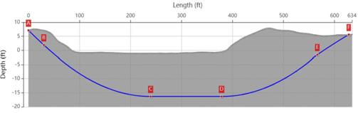
Figure 1. Profile view of a borehole path design.
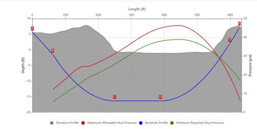
Figure 2. Borehole stability analysis.


