28 minute read
Tech feature: Tackling calibration

from Auto Channel 48
by Via Media

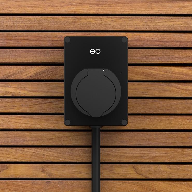
An ADAS target frame and accessories from Delphi, now Aptiv
Getting to grips with static calibrations
Advertisement
LEARN ABOUT THE EQUIPMENT OPTIONS AND VEHICLE CONSIDERATIONS YOU NEED TO KEEP IN MIND WHEN PERFORMING STATIC CALIBRATIONS IN YOUR WORKSHOP
If you’re delaying getting into servicing ADAS (Advanced Driver Assist Systems), don’t delay too long. Governments around the world agree with vehicle manufacturers that ADAS saves lives and reduces collision damage. This means they’re here to stay and will continue to become more commonplace than ever in your bays. Many advanced (and profitable) repair workshops are manoeuvring their way through the complicated maze of ADAS sensor diagnostics and calibrations, but doing it properly — and that is the only way to do it — will not be a simple or cheap endeavour. ADAS service joins a long list of other complicated technology challenges we’ve faced and adapted to.
The ‘human’ side of ADAS

If every ADAS-equipped vehicle could calibrate itself as well as it performs its advanced driver-assist duties, we could breathe a big sigh of relief. Instead we are faced with an ever-growing number of complicated calibration procedures and tools to juggle (Figures 1, 2). And there are not one, but two main types of ADAS sensor calibration procedures — ‘static’, when the vehicle is parked; and ‘dynamic’, when the vehicle is being driven. In both cases, the vehicle’s system can be ‘learning’.
In most cases, both types of calibrations will require an enhanced OEM-level aftermarket scan tool, or true factory (dealer) scan tool. Some manufacturers require either static or dynamic calibrations, while others require both. Static calibrations (typically in your bay) require the most equipment, workshop floor space, and time. If you are just beginning to do your research on what type and brand of static calibration equipment fits your needs (and budget), there are two big factors to consider:
First, the equipment is costly. Whether you opt for a collection of pure OEM tools (as used by the dealers), or a choice from a growing list of aftermarket providers, plan on spending tens of thousands of dollars if you want to calibrate multiple vehicle brands. But keep in mind that diagnosing pre-OBD vehicle drivability problems was best accomplished via a big box engine analyser which cost many thousands of dollars 35 years ago, and still made a decent return on investment. In today’s dollars, ADAS equipment is almost certainly less. Choices are abundant in ADAS camera/radar static calibration equipment, and they can be broken down into several categories and subcategories, starting with OEM and aftermarket.
OEM/Dealer equipment
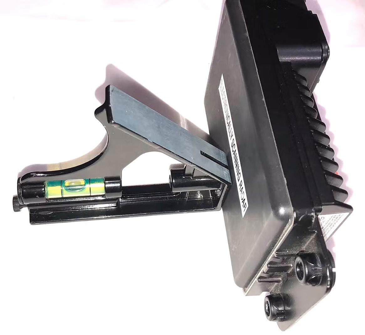
OEMs mostly use a geometry-based target placement process using common carpentry tools such as a plumb bob to find the exact centre of the front (and back) of the vehicle (Figure 3). Note you will need to check the manufacturers’ specifications. This allows a technician to locate and mark the vehicle’s geometric centre. Lines are then drawn on the workshop floor (i.e. chalk lines/ tape/markers) along with various angles to set the camera static calibration target(s) and radar sensor reflector (mounted on stands) at precise position/ distances in relation to the vehicle (Figure 4). Note that you will need to use an area of floor that is known to be flat and ensure you have clear space in which
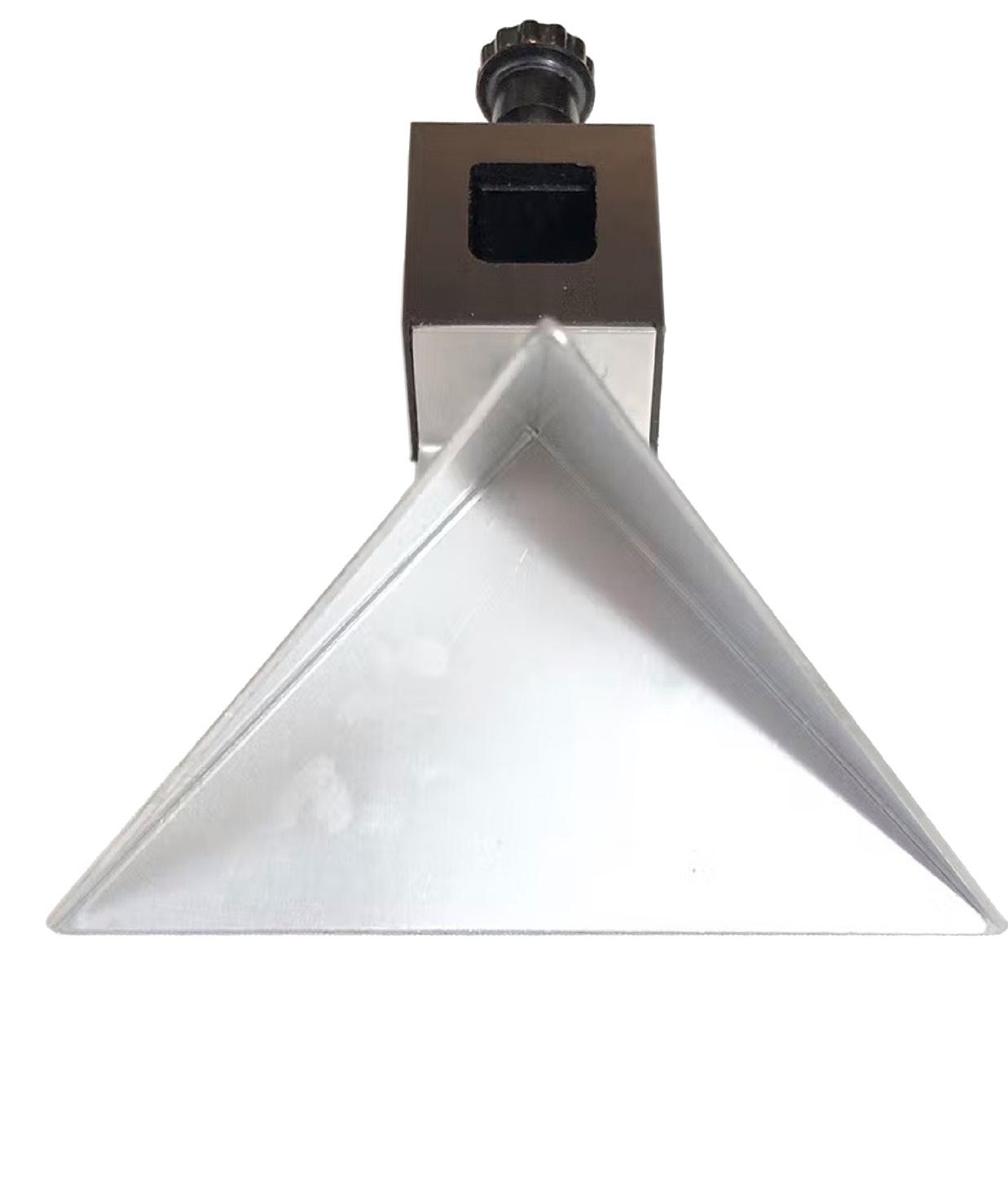
OEM camera target for Honda static calibrations This pyramid shaped reflector is common to Toyota and several other OEMs
to set up targets. A factory scan tool is then connected to issue bi-directional requests to the ADAS sensor being calibrated. The scan tool tells it to lock on to that target to finish the static calibration process. Laser measurement instruments may be employed to speed up this time-consuming process.
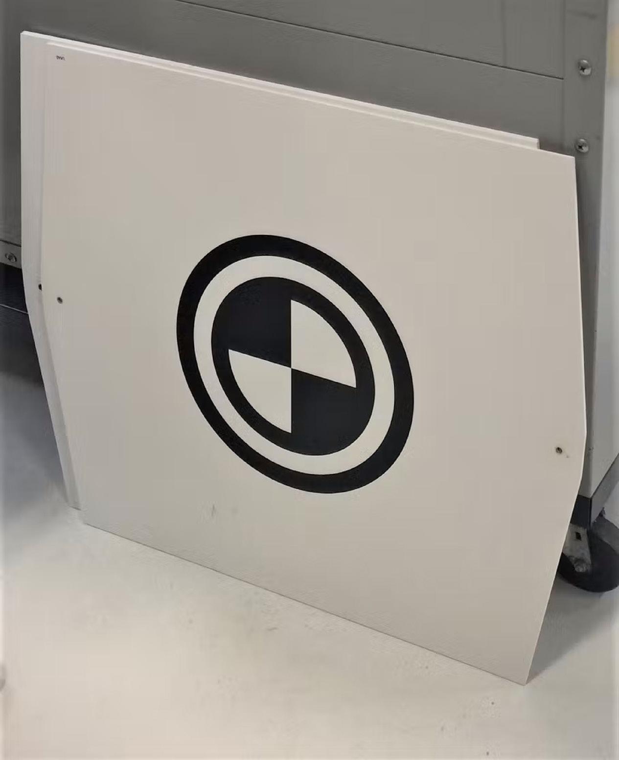
Aftermarket – Stand-Alone target frame
An aluminium ‘frame’ with arms to mount targets, lasers, and tape measures is set in place in front of the sensor being calibrated (Figure 5). As with OEM’s static calibration equipment, the position of the visual (camera) target(s) and/or reflector (radar) target must be precise. Wheel-mounted heads (with clamping brackets resembling chassis alignment heads), in conjunction with tape measures/lasers, may speed up the process of finding the centre of the vehicle. This is required to geometrically place the calibration targets in the precise location in front of the vehicle. This emulates the vehicle manufacturer’s target placement position, but can often take less time to accomplish compared to some OEM methods.
Aftermarket Target Frame with chassis alignment equipment integration
Because ADAS calibration procedures require the vehicle to be on a level surface, alignment racks (which must keep the vehicle perfectly level anyway) have recently become a handy piece of equipment to mount ADAS calibration tools. Several chassis alignment equipment companies are getting into the ADAS calibration tool market. Some aftermarket stand-alone ADAS calibration systems (i.e. Autel) can adjust the height of their target frame arms (and tool calibration software) to accommodate the raised height of the vehicle while parked on an alignment rack.
The second consideration is weighing OEM vs. aftermarket ADAS calibrations. Some deem this a modern-day Hatfields vs. McCoys. While the OEM vs. aftermarket parts, info, and equipment debate is nothing new to our profession, ADAS has heated this feud. In the ADAS calibration debate, the ‘McCoys’ cite the obvious — we’ve been using aftermarket tools to work on other safety systems for decades without the vehicle repair field turning into a disaster. The OEM ‘Hatfields’ cite multimillion-dollar lawsuits being filed (and won) overseas by victims of accidents blamed on non-OEM service procedures.
Ready to give up on ADAS? Don’t!
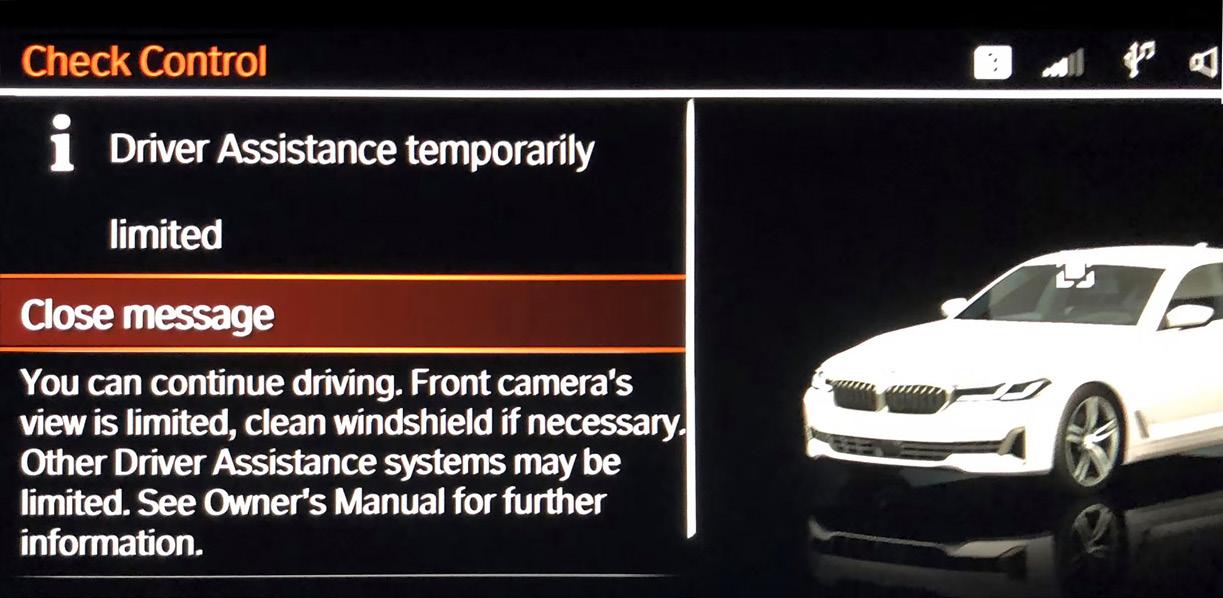
If your business has a large volume of GM or Ford vehicles, complicated (and expensive) ADAS static calibration equipment is not required in many cases for the forward (windshield mounted) camera and long-range radar sensor, i.e. Adaptive Cruise Control (Figures 6-9). Cameras in the outside rearview mirrors used for ‘around view’ (a.k.a. surround view/bird’s eye view) may still require camera targets (visual pattern target mats) positioned at specified distances from each side of the vehicle for static calibrations. Some Honda and Subaru models may also require both static (in the workshop) and dynamic (on a road test) calibration procedures on their ADAS sensors. Toyotas require static calibrations on their camera and radar sensors. Their factory calibration equipment is not overly expensive and any J2534 programmer will work well with a Toyota factory scan tool software (TechStream Lite) subscription. Further education and factory/dealer equipment on ADAS calibrations for GM, Ford, and Toyota aren’t likely to bankrupt you as you gradually get into the calibration field.
Chassis alignment – cause or cure for ADAS calibrations?
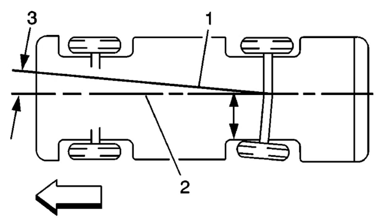
Many OEMs advise performing an ADAS calibration if a chassis alignment changes the vehicle’s ride height. All OEMs (that I’m aware of) stipulate the thrust angle must be correct (no dog tracking) before performing an ADAS calibration (Figure 10). This makes total sense even if the steering wheel is not visibly off-centre while driving straight. ADAS radar and camera sensor static calibrations rely on their targets being placed in exact positions relative to where the vehicle will be moving. Why go to the trouble of lining up the exact centre of the front and rear of the vehicle in your ADAS calibration if that centre line is not where the vehicle’s camera and radar sensors will be looking? On vehicles with positive or negative thrust, the vehicles’ sensors will be looking toward the left or right, instead of at the vehicle your customer is following.
The static calibration completes/passes on the scan tool, but the process was flawed.

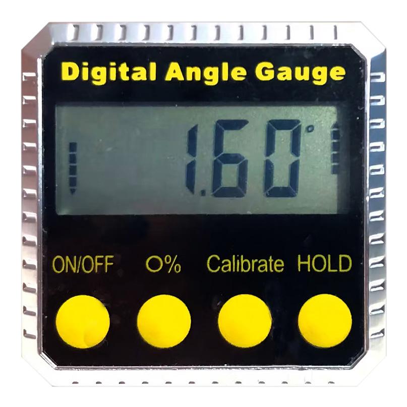
Use a digital angle gauge to adjust the ACC radar’s vertical aim A laser distance finder can help in geometric static calibrations This Miller tool kit can be used to adjust the ACC radar sensor
Is close good enough?
According to Dirk Fuchs, ADAS instructor for I-CAR, thrust lines that are off — or ADAS sensor calibrations that are 1 degree off — equate to the potential for up to a 1.5-metre lateral miscalculation at 100 metres of distance between your customer’s vehicle and another vehicle. The result might be a false ADAS intervention (vehicle braking/stopping for no reason), or worse yet, an accident.
Vehicle ride height/sensor vertical accuracy
A favourite custom modification for many vehicle owners is changing the ride height of their vehicle with lift kits, lowering kits, custom wheels, and the like. This can make an ADAS sensor ‘look’ at the pavement (instead of another vehicle), or ‘look’ towards the sky. Potential missed hazards and false triggers can occur with vertical inaccuracies, too. Car makers are concerned enough about sensors having precise vertical calibration accuracy that many specify verifying the following before static calibrations:
• Correct tyre size and inflation • Empty boot/cargo area • Full fuel tank • Wisdom from a mobile tech
Shouldn’t ADAS Inaccuracies set DTCs? Sure, but shouldn’t other vehicle issues such as leaky EVAP systems and intermittent misfires? Sometimes you have false DTCs, sometimes you have real problems without DTCs. That’s just the nature of today’s awesome (but not perfect) automotive self-diagnostic technologies. To make that point, Mike Reynolds, owner of Mobile Automotive Service Solutions in Charleston, South Carolina, posted one of his case studies in a video. Mike was asked to look at a 2020 Honda Odyssey repaired by a collision workshop after frontal damage. After leaving the collision workshop, the customer noticed the Honda SUV’s adaptive cruise control did not function. Mike took the vehicle on a road test. After activating the ACC (Adaptive Cruise Control), the vehicle did not attempt the proper auto braking intervention while approaching another vehicle. A return to the collision workshop for an inspection of the ACC radar sensor revealed a slightly bent mounting bracket missed during the collision repair. The radar sensor was essentially looking ‘over’ the top of the vehicles it was following. The workshop replaced the bracket, Mike performed the proper factory calibration of the sensor, and all ended well.
Windscreens tell a story
Quality glass/OEM windshield/clean? Obviously, a bug-covered windshield can cause camera issues, but so will poor-quality glass, as it distorts the camera’s view. Look at the logo on the windshield and do your research to determine if it’s what the vehicle needs. Glass quality and cleanliness issues may or may not set a DTC, but can reduce the system’s confidence/performance level (Figure 12).
Is there a disability placard on the mirror? Disability placards commonly indicate the primary driver is older. Older drivers may need extra education and encouragement from the experts at their repair workshop on how these systems operate. Adaptive cruise control (ACC) and lane keep assist (LKA) might take them by surprise.
Is the lane camera overheating? This only sounds crazy. What happens when you put your phone on a windshield mount on a sunny day? It can overheat and shut down to prevent damage. The same is true for windscreen mounted ADAS cameras. Cameras and radars have heaters built into them. Those heater sensors can fail (like O2 sensor heaters burning out) and stay on. One GM PI (Prelim Info) bulletin states “cool the cabin down with the A/C to restore LKA and ACC functionality”. I understand the LKA part because it relies on a camera to ‘see’ lane markings. But why would the grill-mounted ACC radar shut down from a windows-up/direct sunlight super-heated cabin condition? Because the two systems work together (sensor fusion) in several aspects of ADAS operation. Whenever circumstances merit calibrating one sensor, experienced techs recommend calibrating both the radar and camera sensor regardless of whether the OEM requires it. Using a more familiar analogy — what drivability tech checks fuel and ignores spark?
Being certain – ADAS confidence
Confidence is not just a software level in an ADAS system. Confidence is another human side of the ADAS equation. Overall, ADAS features input far more positive variables into our customers’ safe driving experience than negative ones. As repair techs, we mostly deal with broken vehicles and vehicle abuses. We rarely hear the positive side of vehicle safety systems — the injuries avoided and lives saved. The worst thing the repair industry can do is to become a negative factor in the ADAS equation. Going forward, we must continue our education on the subject, carefully research (and purchase) quality calibration equipment, document every process involved, and follow every instruction from the vehicle manufacturer whenever performing calibrations. When performing static calibrations, it makes sense to be certain at every step.
Diagnosing a neglected engine

TECHNICIAN TIMOTHY JONES RECKONS NOT ALL PROBLEMS ATTRIBUTED TO GASOLINE DIRECT INJECTION OF GDI ENGINES ARE THE MANUFACTURER’S FAULT
I’m not sure what it is about Hyundai vehicles that come into our workshop, but it looks like every one of them is at their first appointment ever. I know Hyundai has its share of problematic engines, especially on their Gasoline Direct Injection (GDI) platforms, but I just cannot accept it’s all on the manufacturer. In my experience, it is almost always the case that the engine is out of oil, the oil filter is not a factory filter, and the air filter is 100 per cent restricted. Yet somehow these engines are getting warranty claims accepted when the connecting rod is sitting on the ground from obvious lack of maintenance. I have heard two different theories on their engine failures: low speed pre-ignition (LSPI), and metal left in the blocks during machining.
Low-Speed Pre-Ignition (LSPI)
When I first heard of LSPI, more commonly known as mega knock, I was sitting in a class by Automotive Seminars presented by John Thornton. I think every one of us in the class was taken aback by this little-known phenomenon. What I remember is that LSPI is difficult to detect, but it’s significantly more violent than a typical spark/knock concern. This type of knock is associated with turbo GDI applications, but also affects non-turbo GDI engines as well. I know Hyundai/ Kia has offered software updates to aid in reducing this condition, but tuning the engine will not eliminate all concerns. Manufacturers are still struggling to maximise power output on GDI platforms because of the problems presented with LSPI.
Another aid has been developed to help minimise this phenomenon. There is a new engine oil additive that has been engineered and will be purpose fitted into the ILSAC gf-6 spec of engine oils. If owners are offered a cheap oil change special for a GDI vehicle, they seriously need to find a more reputable garage. Luckily for this customer, they managed to get the last year available for the Tucson without a GDI application, otherwise they may have already needed an engine or two (Figure 1).
The issue exhibited
A 2013 Hyundai Tucson with 70,000km on the odometer came to our shop with a start-stall condition, as well as a check engine light. I performed an auto scan and found a p0017 in the engine controller.
I noticed that the oil change sticker was well overdue by mileage. I confirmed the concern and, sure enough, the engine would start and stall. If I added some pressure to the accelerator, I could get the engine to continue to run off idle. The idle quality was terrible, but as I increased engine speed the engine ran well. To my surprise, there was oil in the engine, and it didn’t sound like it was going to explode.
I had an idea about what was wrong with the vehicle from simply manipulating the gas pedal and understanding the nature of the DTC stored in the PCM. I thought that a cam jumped time or a cam phaser was stuck outside of its normal default/base position. This came to mind because when I was in the driver’s seat (being mindful of the symptoms the engine presented), I was reminded of what a stuck open EGR valve felt like. I decided that I need to back up my hypothesis with some relevant scan data. I’m thankful that some manufacturers saw the need for accurate cam timing PIDs and answered the call. It seems like some manufacturers are embracing the need to have accurate numbers regarding cam position, while others severely lack capability. When a DTC sets on a GM vehicle, the numbers are replaced with zeros. I am baffled as to why any manufacturer would think that would be a useful way to deal with cam timing PIDs.
In my experience, when dealing with exhaust camshaft position PIDs, they usually incorporate a minus sign (-), whereas intake camshaft position PIDs reflect positive integers in the PID value (although I have seen a couple of curveballs that don’t conform to that last statement). I have seen that when an intake cam on VW/Audi products has jumped into a retarded position a (-) can show up before the intake PID value. This is a dead giveaway that you have a mechanical problem. There are typically two possibilities that cause this: • A cam reluctor has shifted on the camshaft • The cam is retarded past its set point
As I started to work through this customer’s concern, I had two questions in my head that I wanted answers to: • When the PCM commands the exhaust cam to move, how does that impact the numerical value? In other words, does the value go more negative or positive? • What are the total cam phase degrees?
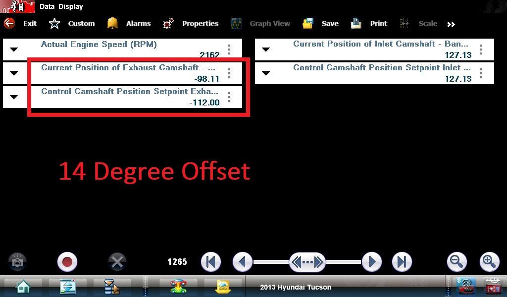
Fig:1
Knowing the total cam phase degrees can support theories on what component may be faulty. This is particularly applicable when a cam phaser has moved to its max travel. On a V-engine design, it’s much easier to obtain known good specifications if the problem is associated with one bank. The reason being is that we have a whole other side of the engine for analysis (the unaffected bank will give you something to compare to).
On a four-cylinder engine, this can raise the level of complexity, as there is no known good to compare to. Sometimes we can get lucky and find that the intake cam phaser and the exhaust cam phaser have the same degree of travel. In the case of this Hyundai, there is a 10-degree difference in cam phase capability between both camshafts. In my experience, when a cam timing DTC is set, we typically don’t have phase control in our bidirectional tests (PCM will not allow). I can only imagine that manufacturers do this deliberately so a collision cannot occur between valves or pistons. After clearing the DTC, the code immediately resets, so I had to get a little bit dirty to get answers to the questions I have. As I pulled up my cam data PIDs, I saw a set point PID of what the PCM desired and I saw a PID indicating what the actual position was. There was
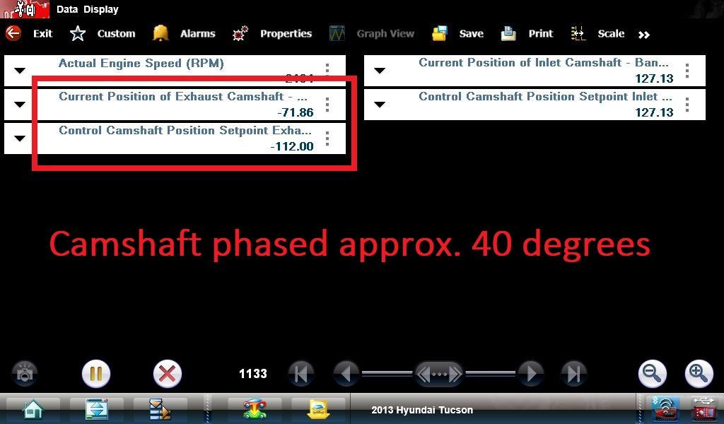
a 14-degree discrepancy (the difference between the -112 degrees ‘desired position’, and the -98 degrees ‘actual position’). I suspected the numbers were not going to match, based on how it was running (Figure 2). This didn’t tell me if the cam moved into the desired direction of travel or the opposite way. If I knew which direction in the numerical scale was ‘retarded’ or ‘advanced’, I could rule out a mechanical failure a lot sooner.
Time to get dirty
In my next test, I full-fielded the exhaust solenoid and phased the cam as far as it would go (Figure 3). What I saw was that the cam’s actual value goes from -98 degrees to -71 degrees (that answers my first question as well as my second). The set point being -112 degrees and the maximum retarded position is -71 degrees. (This equates to roughly 40 degrees of phase-angle.)
Since the cam moved in the direction that the PCM would normally move it in, I suspected that the cam solenoid valve may not be returning to its resting position. Some other possibilities include: • The camshaft phaser has a mechanical issue • The chain jumped one link • There is a hydraulic failure in the engine, outside of the solenoid
Let’s reach for the low-hanging fruit. A known good cam/crank correlation
waveform is available in the service information from the manufacturer. That also meant I had to get my scope and hook it up to the car. I felt confident that I could accurately diagnose this vehicle’s fault.
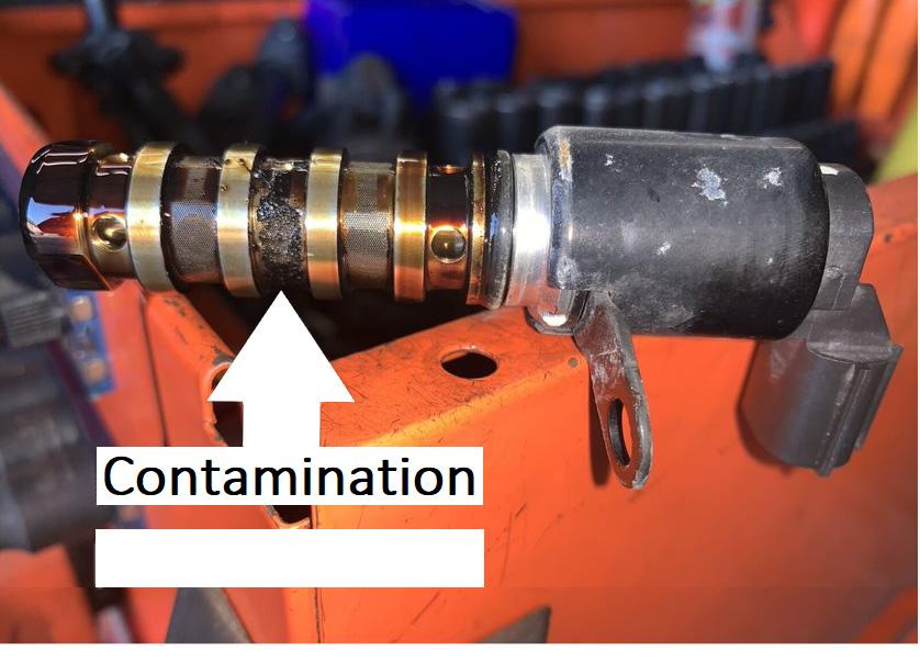
The exhaust cam solenoid on this engine is very accessible. I removed the solenoid for physical examination. When I took it out, I saw how neglected this engine was. The solenoid was contaminated with oil deposits and carbon (Figure 4). When I shined my light through the solenoid oil passages, I could tell the solenoid valve wasn’t returning to its resting position. I used a can of brake cleaner and an air gun to clean the solenoid out. I used my jump pack and powered the solenoid quite a few times. This allowed the valve to return to its resting position.
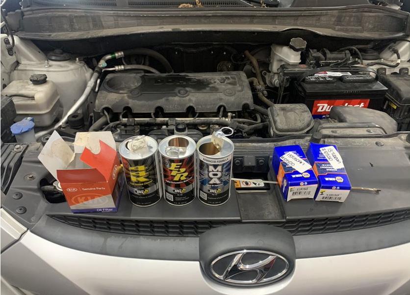
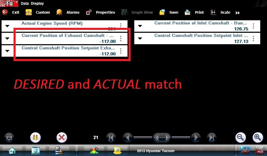
I installed the solenoid back into the engine and boom! The engine started and ran fine at idle. I noticed as well that my desired cam timing and actual PIDs agree (Figure 5). This car isn’t fixed yet because I still have not addressed the root cause of the problem. If I allow the customer to leave with the car right now, without servicing the oil, a comeback is sure to follow. I recommended the service advisor suggest the replacement of both cam timing solenoids and a BG EPR oil change service. BG EPR is a chemical supplement that is added to the engine oil before the oil change is performed. This chemical is engineered to break down sludge, release stuck piston rings, and de-gunk other engine internal components. I have personally seen some truly fantastic results after performing this service (Figure 6).
When I perform a BG EPR service, I like to actuate the solenoids. Doing this helps clean them out and get engine oil/chemical into the cam phasers. BG does not recommend driving the vehicle or raising the engine rpm past 1200 with this product in the oil because it can significantly dilute the engine oil and cause bearing wear or damage. Since we are a professional shop, we understand the value of using quality parts and materials. We always install a factory oil filter on the engines that have experienced repeated mechanical failures. Hyundai has also released technical service bulletins advising on engine knocking noises associated with aftermarket filters. Oil changes are not very profitable in most circumstances, but it’s not worth blowing up an engine to save a few dollars on a cheaper oil filter.
The more time I’ve spent in this industry, the more I have come to desire quality parts. To find quality, our parts are more frequently sourced from the dealership. There are some instances where an aftermarket part outperforms the OE, but I often request an OE part, especially if we have had issues with aftermarket parts with certain applications. The longer the suggested labour time is for a part replacement, the more likely it is that I want to put an OE part in the vehicle. I couldn’t imagine performing a 15-hour heater core replacement and using the cheapest component you can get your hands on, only to have to disassemble the entire vehicle again, due to a part failure. This is not just the warranty labour/time you are eating. All the production lost from other jobs you could be profitable on is compounded. In the case of this Hyundai, the labour/time for an oil control valve is 0.5 hours. Many times, I do not have any control over where the part comes from, I can only make a suggestion. After all, businesses exist to be profitable. I think this is often a source of frustration for professional technicians. We want to give the best quality repair to the customer and gain the maximum efficiency for both ourselves and the shop.
After I performed the oil/filter change, I replaced both oil control valves. I cleared out the fault codes, and drove the vehicle out of the bay for a final road test. Shortly after driving, the malfunction indicator lamp came on, which meant I headed back to the shop to grab my scan tool, and scanned for DTCs. This is what was stored: P0080 Exhaust cam solenoid circuit high.
I was thinking to myself that I remembered plugging the connector in, but I wanted to recheck my work. I examined the solenoid and found the connector fully seated. I removed the connector, plugged it in, and it felt normal to me. I approached the service counter and advised them to order the solenoid from the dealership. I felt confident that this would fix it because the original solenoid didn’t have a circuit fault (just applying some logical thought to the situation).
I removed the replacement solenoid from the engine and found one of the male terminals bent up in the solenoid connector cavity. I have seen this a few times in the past. The only thing I could think of that would cause this issue is someone attempting to mate the connector incorrectly. If the connector doesn’t seat easily, there is probably a valid reason. I told the service advisor that I wouldn’t recommend bending the terminal back because it is difficult to ensure a proper connection between the male and female terminals. We installed the OE part from the dealer and the vehicle has not been back.
With a firm understanding of how the hydraulic portion of the VVT system functions, my instinct allowed me to visualise what was wrong with the vehicle. Without taking the time to familiarise ourselves with the systems we work on, we often begin our analysis far from the actual fault, and as a result invest a lot of unnecessary time. In this case, I had to use the scope to prove what was wrong with the vehicle, not that there is any wrong in going that route. But I’d always prefer to remain efficient as well as accurate. The moral of the story is to take the time to learn about the ins and outs of the systems and components we face daily. Familiarise yourself with the tools you have and learn what they can and cannot show you. Your accuracy is likely to increase, just like your profitability and confidence.
Fig:4 Fig:6
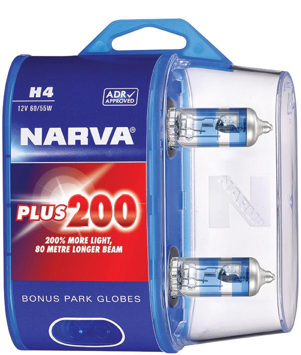
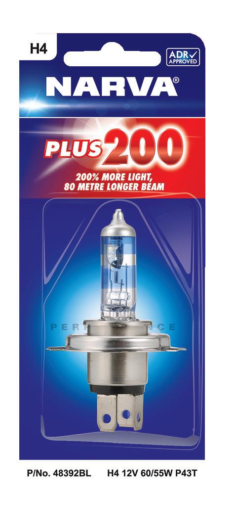
Halogen still the best upgrade for headlights
LEDS ARE SETTING THE PACE IN MANY AREAS OF LIGHTING, BUT A NEW RANGE OF NARVA HALOGEN BULBS IS STILL THE BEST LEGAL UPGRADE FOR CONVENTIONAL VEHICLE HEADLIGHTS

Narva’s new Plus 200 halogen performance bulbs are more than twice as bright as standard H7 bulbs and the beam penetrates 80 metres further ahead. The light is also whiter, rendering objects’ colours closer to their appearance in daylight.
The new-design bulbs also achieve this improvement with no increase in power consumption or heat, making them suitable for use in vehicles with polycarbonate headlamp covers.
This makes the new bulbs, which are available in both H4 and H7 fitments, a simple swap. They are ADR-approved and are a fully legal and compliant upgrade in New Zealand.
This is likely to make sticking with halogens — rather than choosing an alternative upgrade path — a more sensible option in the future, thanks to a recent change affecting compliance with the 2004 Vehicle Lighting Transport Rule.
An amendment to the vehicle inspection requirements manuals, or VIRMs, gazetted on 9 May this year, gives vehicle inspectors the ability to check the condition of vehicles against the National Motor Vehicle Title Information System (NMVTIS) — which shows its original specifications — to assist with proof of standards compliance. That gives the inspectors confronted with an aftermarket lighting installation, such as a replacement LED headlamp array, the right to deny a vehicle a warrant or certificate of fitness because it was not a standard factory fitting.
The new Plus 200 bulbs are the most powerful lamps in the Narva range, making them an ideal upgrade solution for any application using H4 or H7 sockets.
They are available as four part numbers — two H4 part numbers, comprising a single or a pair of bulbs, and the same in H7, as follows: Part number 48392BL has a single H4 12C 60/55W P43T Plus 200 bulb, while part number 48392BL2 has a pair. Similarly part number 48396BL has a single H7 12C 55W PX26D Plus 200, and 48396BL2 has a pair.
Narva’s new Plus 200 halogen bulbs are available at auto parts stores nationwide.


K ° 3750
* Compared with standard halogen globe


STREET
LEGAL
PERFORMANCE HALOGEN GLOBES
Features l Up to 200% more light on the road* l Up to 80 metres longer beam l 20% whiter light* l ADR approved and street legal l Suitable for polycarbonate headlamps l No increase in power consumption or heat
SINGLE BLISTER PACKS 48392BL H4 12V 60/55W P43T * Compared with standard halogen globe48396BL H7 12V 55W PX26D TWIN BLISTER PACKS 48392BL2 H4 12V 60/55W P43T 48396BL2 H7 12V 55W PX26D
Quality fluid handling pays unexpected dividends
INVESTING IN QUALITY FLUID HANDLING EQUIPMENT DELIVERS BOTH TANGIBLE AND INTANGIBLE BENEFITS
Many businesses, especially when times are tough, look to spend the minimum on relatively low cost equipment like oil pumps, drum trolleys and drain trays, but James Driscoll, director of equipment supplier Emco, says that’s often a false economy.
He has seen the difference a shift to better quality equipment has made which extends beyond the physical workshop, as creating a better place to work leads to greater satisfaction in the people working there.
Emco is often contacted by workshops that have become frustrated with breakages, spills, leaks, and the downtime spent on repairing or attending to poor equipment.
“Often people are responding to the need to tick boxes for health and safety, and environmental compliance,” he says. But what they get from better quality solutions is little short of business transformation.
“What I’ve seen over many years is people looking to get by with equipment that’s low quality and cheap and ultimately it can fail early in the piece, leaking out product. When fluid handling equipment starts to break down, having to deal with that is not just downtime, it also creates significant environmental issues, health and safety risks from slips and trips, exposure to fluids, contamination issues, and knocks and bruises.
“It also leads to frustration which affects work performance.” He says working in an environment where fluid spills are common and working in a mess is tolerated has a psychological effect that could translate into people not caring about the quality of their work.
Providing quality equipment or installations reverses that situation, says James. “Good quality equipment can lead to pride and increased staff performance and efficiency — as well as improved environmental performance and reduced health and safety risks.”
Taking the next step, shifting from pumping products from drums to a fixed line installation, accelerates those gains. James is a big fan of bulk storage and fixed line installations, having seen the difference that has made in many workplaces.
The initial investment is always repaid in increased efficiency in accurate dispensing and avoidance of spills, he says. In addition, removing the need to handle drums or transfer pumping equipment avoids potential contamination, creates a cleaner and tidier workshop, and further reduces hazards. “It takes away uncertainty and creates consistency.”
What’s more, an attractive well-designed pipe layout makes a physical statement about workshop quality and efficiency that speaks to staff and customers alike, says James.
For more information on fluid handling products or installations, call Emco on 07 850 5240.


LET’S KEEP THINGS MOVING
TALK TO EMCO FOR NATIONWIDE DISTRIBUTION AND INSTALLATION OF EQUIPMENT FOR LUBRICANTS, FLUIDS AND GASES.

EMCO offers an extensive range of premium reticulation products with the highest levels of functionality and design, from quality manufacturers across the globe.
Our team of determined problem-solvers are passionate about quality, service and doing what’s right for you. EMCO products and installations solve even the most technical of reticulation challenges.