4 minute read
Troubleshooting — deranged Ranger

from Auto Channel 52
by Via Media

2013 Ford Ranger (picture source internet)
Renegade Ranger
Advertisement
A DESCRIPTION OF AN AECS TECHNICAL HELP DESK PROBLEM AND HOW IT WAS SOLVED
A2013 Ford Ranger 3.2-litre five-cylinder common rail turbo diesel was presented by a workshop to another workshop which is high up on the ladder in diagnostics.
It came into the workshop with problems not starting. Pump pressures were checked and could not be faulted. It now starts but has no power.
The workshop asked for help in diagnosing the ‘RPM Differentiate’ function on its ATS scope, suspecting a high-pressure pump problem.
The diagnostician posted the ATS scope recording below tracing from idle to wide open throttle where it was starting to die, sounding as if it was missing as well.
Not everyone likes mathematics, but when the recordings are modified through the calculation capabilities of the ATS scope, some very interesting conclusions can be drawn. Have a look at what we did below — you will like it if you take the time to digest it, and it will make you better at your job. Plus, it is pure fun!
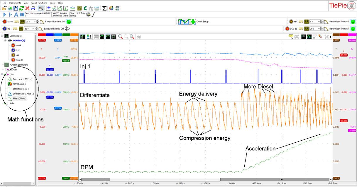
The crankshaft sensor signal is transformed into an RPM line, which shows the speeding up and slowing down of the crankshaft as a result of compression and combustion. The RPM line can be recalculated into a differentiator, which shows the steepest parts of the RPM line (the biggest changes). The differentiator line now represents compression energy (slowing the crankshaft) and combustion energy (speeding up of the crank), irrespective of engine speed.
During Idle you can read in the differentiator line a clear and steady energy delivery and compression energy. They keep each other in balance — that is why the RPM does not alter much.
However, look at what happens when the accelerator gets pressed. More diesel gets injected, so energy delivery gets higher, winning energy from the compression. That results in increasing RPM (acceleration on the RPM line).
The compression energy is reduced a little during acceleration as the flywheel distributes more energy during acceleration. However, in the latter part of the Differentiate line you can see that the compression energy used increases (the lines drop lower) as a result of the turbo gaining momentum and starting to fill the combustion chamber with more air, making it harder to compress, or taking more effort to bring up the piston.
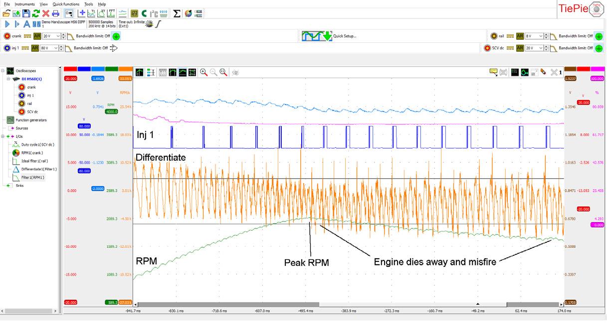
In the above picture you see the Combustion energy lower to the point where the Compression energy has more effect, lowering the RPM after peak RPM. A misfire is also visible and the rail pressure has dropped really low and is wavy.
When looking for a reason for the misfire and the engine dying away, you will have to look at the amount of diesel entering the combustion chamber. The amount of diesel is controlled by rail pressure and injection duration. When the engine gets past peak RPM in the recording, the injection pulse width has dramatically increased, trying to get all it can out from the rail. The ECU has tried to control the rail pressure by increasing the SCV opening rate. The rail pressure is still dropping, and on top of that the signal is really wavy and not in sync with the injectors. This indicates that it is not, for example, one poor quality injector.
Same ATS scope recording during misfiring and dying

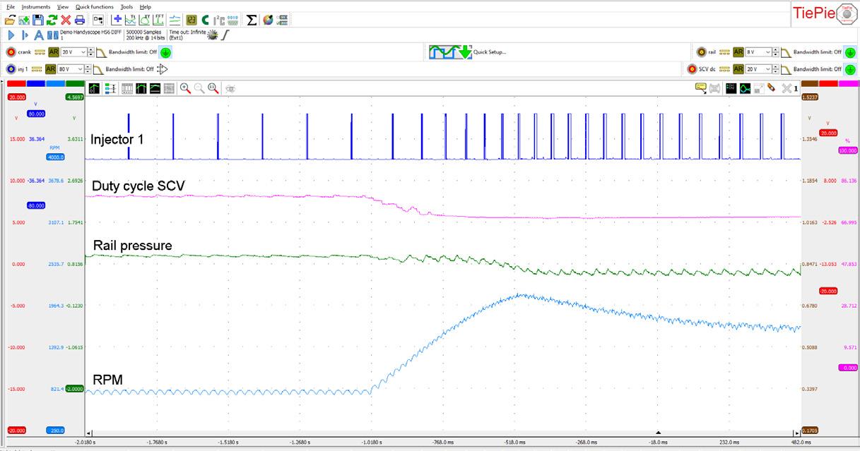
ATS 6004XM differential/offset scope recording of Inj1, suction control valve, rail pressure sensor, and crankshaft sensor Same ATS scope recording focussed on the rail pressure
THE PUMP
It must be the pump. The three-plunger pump on this vehicle is not timed and not running in sync with the injectors. The crank gear has 21 teeth and the pump gear has 28 teeth. Looking at the recording, the pump elements are in sync every eight revolutions.
The help desk suggested that this pump probably had two non-working pump elements as in broken or sticky springs, and should be replaced.
The diagnostician confirmed when the pump was dismantled that two of the three elements had collapsed springs.
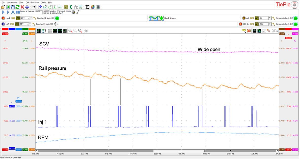
Above is the trace after the new pump was fitted. With a little automotive mechanical skill, you can read an enormous amount of valuable information from one simple recording made during a quick rev-up in the workshop. For those who think a lot of luck is involved in this game, I can assure you that it is not. It requires a healthy dose of thinking power, AECS quality training, AECS equipment and, in this case, a little bit of tech support.
How to read signals like these is taught in AECS ATS1-3 (New) scope training, and the DMS training series.
Same ATS scope recording but with more maths added
ATS scope recording with new pump fitted


