
10 minute read
Preparing for the workshop of the future

from Auto Channel 54
by Via Media

MOTOR VEHICLES HAVE CHANGED SIGNIFICANTLY OVER THE PAST 50 YEARS BUT THE EXPECTATIONS OF OUR CUSTOMERS HAVEN’T. EVERY VEHICLE OWNER WANTS TO DROP OFF THEIR CAR AT THE LOCAL SERVICE CENTRE AND KNOW THAT EVERYTHING WILL BE CHECKED AND MAINTAINED CORRECTLY
As an industry we’ve adapted and met our customers’ needs, and even offered them wi-fi, a caffeine hit, and an EV charge along the way.
Advertisement
The arrival of electric vehicles (EV) and hybrids brings new challenges. EV and hybrids account for around 10 per cent of new vehicle sales. It’s going to take some time to switch out the 4 millionplus vehicles with internal combustion engines on our roads, but there will be a shift in servicing requirements and New Zealand workshops can start to build that into their businesses today.
WHAT WILL AN EV SERVICE LOOK LIKE?
This is a big question that many workshops are looking at when planning investment. We are already starting to see less investment in oil and lube equipment and more emphasis on other services such as brakes, tyres, wheel alignment, air-con, ADAS calibration, and batteries.
Most EV brands suggest a six-monthly service to check over the batteries and we need to take these recommendations and build full-service packages around them, including checks such as:
• Battery testing and reporting
• Wheel alignment and tyre care
• Brake and suspension checks
• ADAS calibration
• Air-con check (R1234yf and R134A gases).
Getting Equipped
If your service centre isn’t handling tyres, you should investigate this as a source of revenue, adding roller brake testing with slide slip suspension plates will round out servicing options for both EV and ICE vehicles, as does air-con servicing and driver assistance system calibration.
Insulated footwear, and Arc flashrated clothing (including gloves and eyewear) are important health and safety additions.
Battery replacement equipment, like the Steiner battery lift table and a solid two-post hoist suitable for battery removal, should also be key considerations. Hoists with asymmetrical or double-jointed arms give excellent access for battery removal (Nussbaum is top of the line here).
Building Your Reputation
It’s going to be a while before the phrase ‘grease monkey’ is greeted with a blank stare from future generations but, in the meantime, we can make sure that when your customer switches to EV or hybrid they can continue to take their car to their favourite mechanic. Treadway Equipped can help make that happen.
For more information, visit Treadway Equipped Complete Automotive Workshop Solutions website: treadwayequipped.co.nz. For more information about the ACDelco battery stockist program, please call 0800 546 000, or visit rjbatt.co.nz.


MISFIRES CAN BE TIME CONSUMING AND COSTLY FOR WORKSHOPS, ESPECIALLY IF THE VEHICLE IS ACTUALLY NOT MISFIRING. SO, WHAT CAN BE DONE TO IMPROVE THE DIAGNOSTICS?
Engine Control Units (ECU) are not without their limitations and sometimes they can wrongly diagnose a misfire.
So, despite the fact that only three things are needed for successful combustion in most gasoline engines — fuel to air ratio, ignition discharge and correct timing, and cylinder integrity — many technicians still struggle to solve the problem and can sometimes spend hours on wild goose chases that lead to purchasing unnecessary parts. What can be done differently?
Know Your Misfires
A misfire is not always a cylinder lacking a combustion event — the true definition is ‘the slowing of the crankshaft’.
When a cylinder fires and combustion happens, the nitrogen inside the air charge is heated by the combustion event. The heat causes the nitrogen gas to expand, and the pressure exhibited on top of the piston helps to propel it down and causes the crankshaft rotational velocity to increase.
If there is inadequate fuel supply, a combustion event will fall short, or it will not be as intense as needed. Both scenarios will slow the crankshaft and be potentially flagged as a misfire.
Secondly, in a scenario when no (or inadequate) ignition supply is available within the combustion chamber, the Air/Fuel (AF) mixture will fail to ignite properly, or at all. Again, this situation will indeed cause a slowing of the crankshaft, and misfires will likely be flagged by the ECU.
Thirdly, when a cylinder lacks integrity, it could be because of one of two different reasons:
1. If the cylinder cannot breathe, it cannot fill adequately with the proper A/F charge, leading to no low compression, or an A/F density issue, where inert exhaust gases displace the A/F mixture — like the EGR effect.
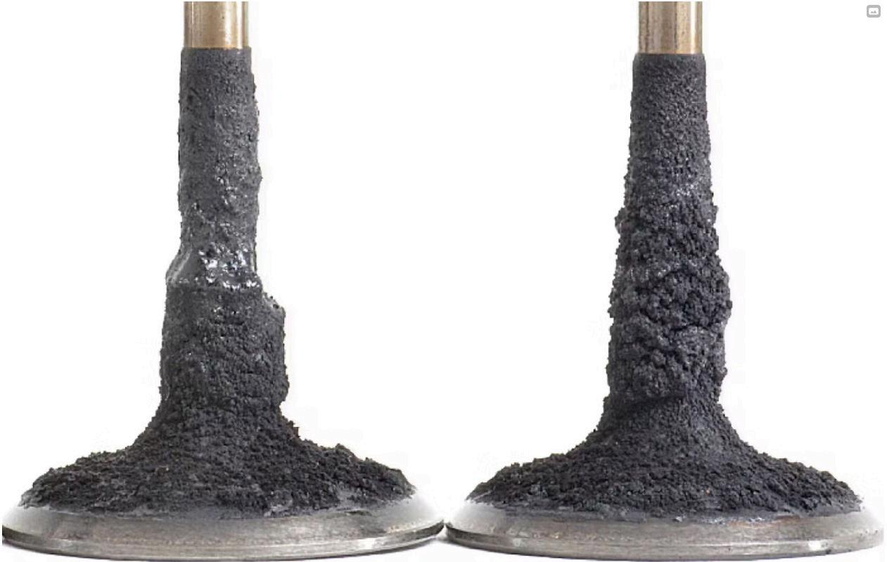
2. A cylinder’s inability to seal properly. This type of fault can lead to a flameout condition (Figure 1). A similar event occurs with the frequent cold-idle misfires we tend to experience on the GDI platforms. The carbon at the intake valve ports disrupts the airflow, and the air charge ‘tumbles’ into the cylinder differently than it is designed to do, and the contribution to the crankshaft rotation is lacking significantly enough to cause misfires/ driveability symptoms (Figure 2).
SO WHY ARE MISFIRES DIFFICULT?
System strategy is often a reason for a misdiagnosis. Many believe that misfire detection is accomplished only by monitoring the changes in crankshaft rotational velocity. The fact of the matter is that there are many useful strategies used to detect misfires and for some vehicles this will require more than one strategy, including:
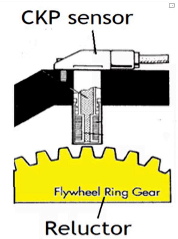
CKP sensor signal frequency: As the crankshaft rotates, its tone wheel (with strategically spaced notches on it) rotates past the CKP sensor (Figure 3). This causes the sensor to output a change in signal voltage. These changes in signal amplitude are what the engine controller is monitoring. As the crankshaft slows, so too does the frequency. The pulses become more widely spaced apart. This is what the engine controller is looking for to determine if a misfire has occurred.
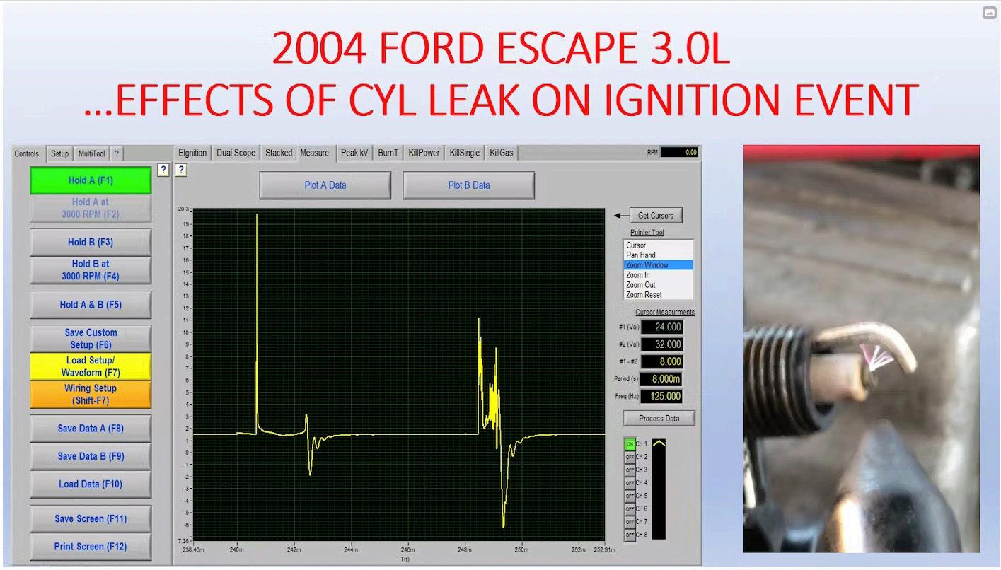
Spark ionisation: This is based on the principles and physics of the ignition system operation. The spark event is very sensitive and reactive to the environment in which it is fired. A spark is a finite event. This means that there is only a set amount of energy an ignition coil can store and discharge. Energy is required to discharge a spark and overcome all combined sources of electrical resistance within the path of the spark. Changing factors like spark plug gap, cylinder compression, A/F ratio, and cylinder contents (like oil or antifreeze), or even changes in resistance from spark plug wires or a weak ignition coil, are the conditions in which the spark fired will change. This will affect the intensity and duration of the spark event. Here is an example of a normal spark event compared to one occurring in a misfiring cylinder, due to a compression leak (Figure 4).
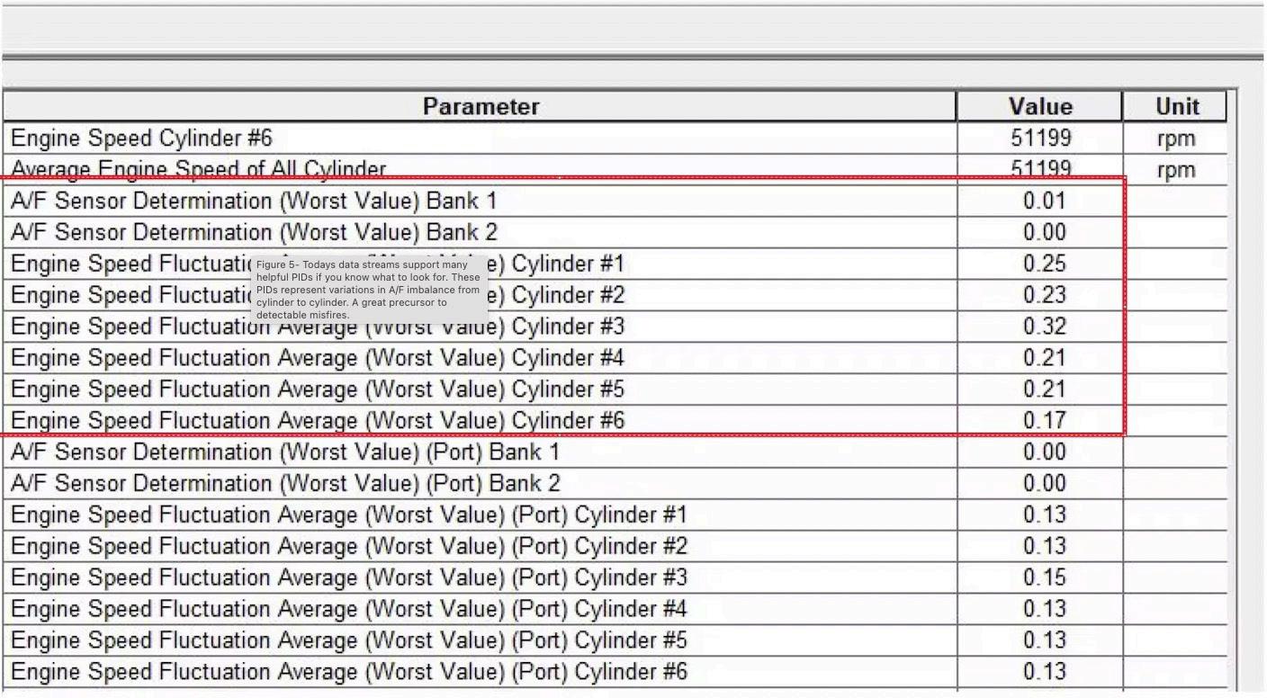
AF sensor signal variation: Technology is brilliant, and the speed at which the data streams communicate sets us up for success, compared to the days of old. With the speed involved in this technology, the response of the heated exhaust gas oxygen sensors (or A/F sensors), and the ECU’s ability to process and display it is tremendous.
The sensor’s speed and accuracy now give the engine controller the ability to detect variations and A/F imbalance, from cylinder to cylinder. As a result, this technology allows us to determine which cylinder may be ‘misfiring’ (via engine data), even before a misfire is flagged (Figure 5).
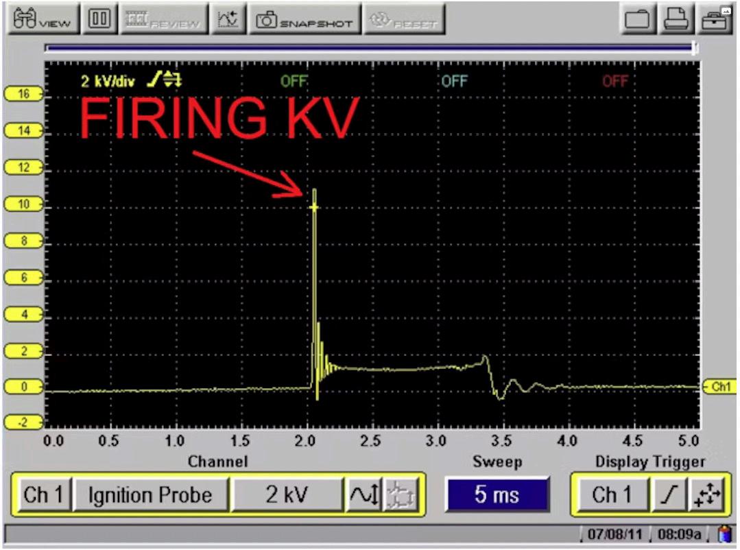
Spark kilovolt (kV) amplitude: Very similar to the characteristics described above in the ‘Spark Ionisation’ strategy. This strategy works from the same principles, however the detection strategy is less sophisticated but still very simple and effective.
When a spark event initiates, it’s the firing kV that is visible as the tall vertical event (Figure 6). When the coil fails to discharge, or the firing kV is significantly diminished, the detection circuit will see it, just as an ignition scope would display it. It’s the software in the engine controller that is designed to recognise a sufficient spark firing kV from a deficiency.
Case Study
Below is an example of preliminary research performed, implementing the proper tools for system evaluation and capture of a fault, along with the root cause of the perceived misfire.
A 2000 Isuzu Rodeo, with nearly 300,000kms on the odometer, arrived with a warning light on. The DTCs were scanned, and a single P0303 ‘cylinder no. 3 misfire detected’ was stored. After talking to the customer, there were no other driveability issues noted. If not for the light, the customer wouldn’t have even realised a fault existed.
Speaking further with the customer, it was found that the vehicle had recently been taken to a local and reputable shop for correction of a driveability concern. The customer couldn’t recall what repairs were performed.
The original Powertrain Control Module (PCM) believed that the no. 3 cylinder was misfiring. Knowing that the oxygen content of the exhaust gas will rise during a misfire, I attempted to snoop this out in scan data, via fuel trim. Elevated fuel trim will be the result of detected oxygen from a misfire (the oxygen that isn’t consumed because combustion didn’t occur). However, the status of the feedback system was in an open-loop default, making fuel trim an unreliable tool for misfire detection.
The question is, “Why does the PCM believe cylinder no. 3 is misfiring?” However, other valid questions may arise, like: “How does this vehicle’s PCM detect a misfire?” and, “What components make up the misfire detection strategy?” However, one of the most important questions to ask after answering the previous ones is: “How can we test the detection strategy for accuracy?”
With a little bit of research, it was quite easy to locate information about this vehicle’s system description and operation of the misfire detection strategy, and the necessary wiring diagrams associated with the system. This system functions quite differently (Figure 7). The PCM monitors what is known as Combustion Quality (CQ) signals.
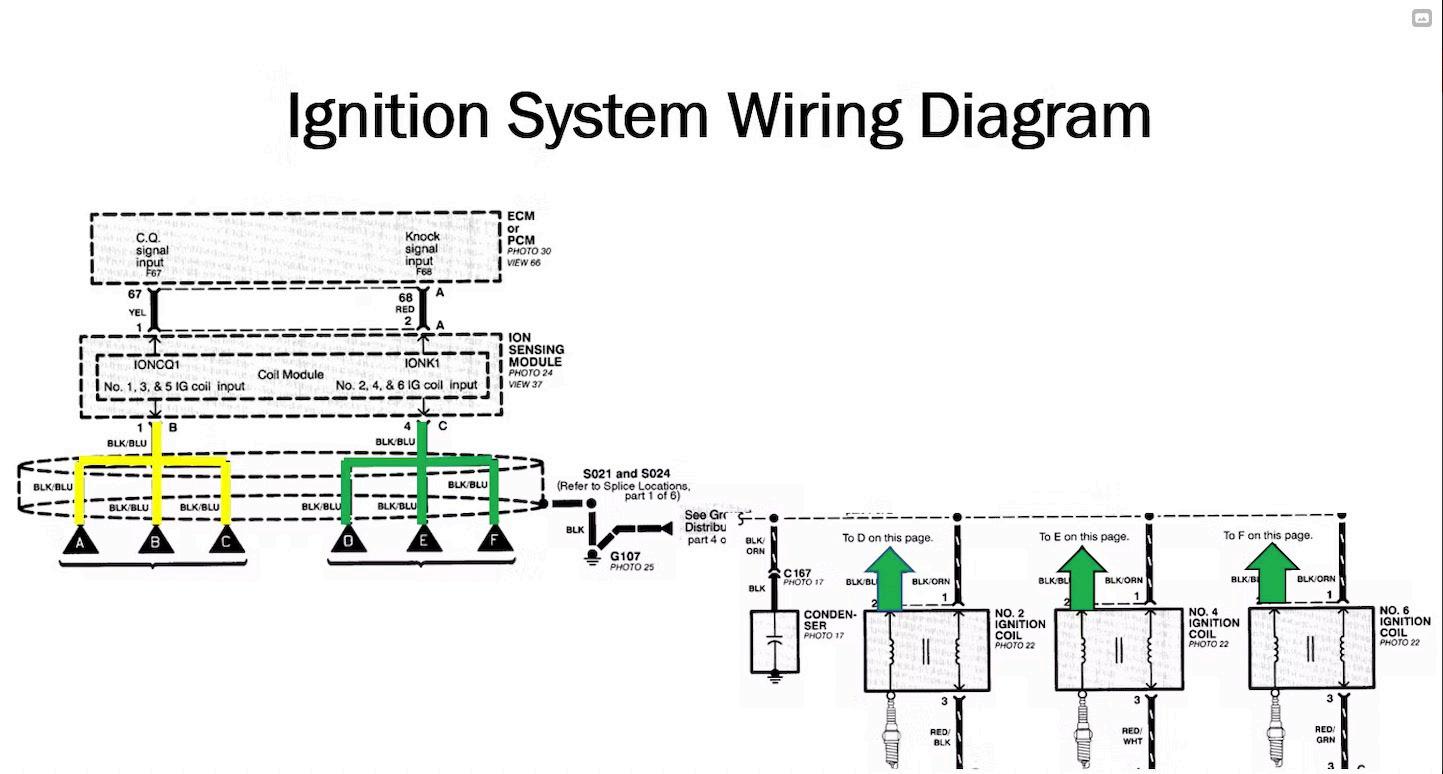
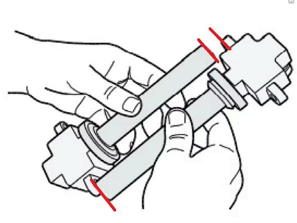
Figure 10 - The comparison of the coils shows two different lengths. The CQ detection circuit proximity has changed relative to the spark plug position. This has caused a perceived reduction of event intensity, causing the PCM to detect a misfire that wasn’t actually occurring assume there is something wrong with the quality of the ignition event, and flags the cylinder as ‘misfiring’. Once the suspect cylinder is identified and under the appropriate load/rpm conditions, the PCM will begin to flash the MIL, and a cylinder-specific DTC is flagged in the PCM memory.
A Plan Of Action
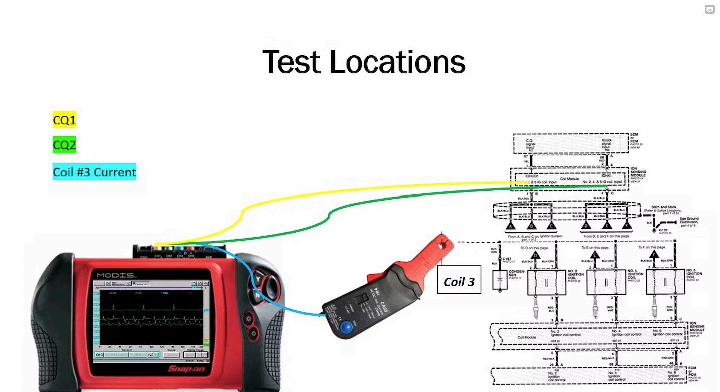
This job requires a multi-trace lab scope to capture the fault and confirm cylinder No. 3 is responsible. I chose to monitor three pieces of data. These three will tell the entire story about what happened, which coil is responsible, and how the other coils look in comparison. All I need to know ahead of time is the cylinder positioning, so I can properly identify coil no. 3.
• On channel no. 1 (in yellow), I will be capturing the CQ signals for Bank no. 1 cylinders.
• On channel no. 2 (in green), I will be capturing the CQ signals for Bank no. 2 cylinders.
• On channel no. 3 (in blue), I will be capturing the coil current trace for cylinder no. 3 (suspect cylinder).
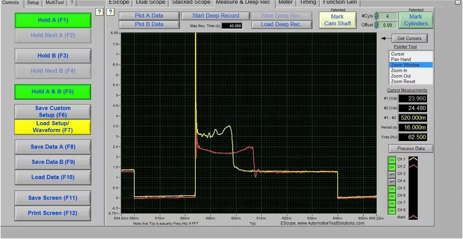
Viewing the multi-trace capture on the lab scope, the blue coil ramps represent when coil no. 3 discharged (Figures 8 and 9). Between the two blue coil ramps are six distinct CQ signals, and all have been encircled. The red circles represent the CQ events for coil no. 3 (suspect cylinder), and the blue circles represent those CQ signals from the other cylinders. The entire lower portion of the CQ signal is missing from our suspect cylinder no. 3.
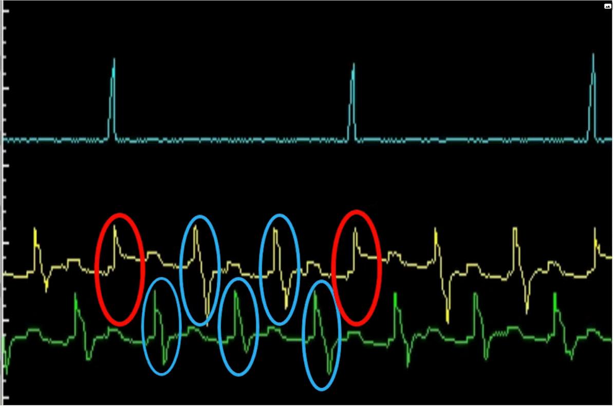
This is the reason for the flashing MIL and P0303. Of course, the root cause still has to be found, but we have the justification to invest more time in this arena and pursue the root cause with further testing.
As the detection circuitry is housed within the ignition coil, the ignition system must be inspected carefully, as there may simply be an issue with a coil, not necessarily a true ignition event fault. Using tools that we have at our disposal, the goal is to monitor the actual ignition events, as they are the input to the coils responsible for generating the CQ signals.
There is one CQ signal reporting to the PCM on two individual parallel circuits — one for each bank of the V6 engine’s coils. These signals are induced by the actual discharge of the spark from the COP ignition coils. The detection pick-up for the CQ signals is located inside each of the COP coil’s integrated circuits.
As a spark from each coil is discharged, a shared circuit (one, from each bank of three coils) reports each of the coils’ CQ signals to the PCM. In turn, if the PCM determines one of the CQ signals is not quite like the other, it can only
However, before getting my hands dirty, a TSB was located relating to the same fault we have been experiencing. It’s been discovered that one of the six coils has been deliberately made to be 7mm shorter than the rest of them. This is to accommodate its positioning in the tight space beneath the brake master cylinder.
Elementary Conclusion
So if this coil is placed anywhere other than in the cylinder no. 6 position, the integrated detection circuit will be further (in proximity) from the spark plug. The resulting induced signature will be altered due to the unintentional air gap. What are the chances the shorter coil no. 6 is hovering over cylinder no. 3’s spark plug? Rather than invest more time in testing, a preliminary inspection of the coil placement seems much more efficient.
As can be seen from the picture here, the length of the shorter coil no. 6 is compared to one of the other five longer coils (Figure 10). The problem is that this shorter coil is not over no. 6 (as it should be), but it is over no. 3 (our suspect cylinder). This occurred during the recent repair noted above — the engine had no misfires whatsoever, but the engine controller certainly detected it as the case.
Misfire detection strategies of today are brilliant, but they have their flaws. For instance, something as simple as a worn axle CV joint, or even a damaged tyre, can skew a CKP signal enough to flag misfires.
The key? Understand the system strategy, reference wiring diagrams, employ the appropriate testing tools, and have a sound knowledge of what they can and cannot do. If you’ve got those bases covered, the rest is simply putting it all into practice.


