
Lifting Equipment Grade 120 I 100 I 80
The traditional KWB brand originates from the chain forge „Kettenwerk Brückl“, an Austrian company with experience in chain production dating back centuries.
Since 2003 the KWB Star Alloy G 100 programme has been distributed successfully worldwide paving the way for the introduction of KWB‘s Sun Alloy G 120 range in 2016.
Constant extension and expansion of KWB‘s lifting product programs over years, today enable us to offer a streamlined and spot on range of products, tailored to meet the growing global demand for top-quality lifting equipment. More than suitable in use; totally reliable.
We offer quality at the highest level.
Our Sun, Star and Super Alloy sling chains and components fulfill maximum requirements with regard to profitability, safety, longevity, easy handling. KWB means safety in action.
Advantages:
• Use of high grade steels and alloys
• Production on specially developed bending and welding machines in Europe
• Process controlled heat and surface procedures
• BG approved – H29 number

• Continous quality control (ISO 9001, 9002) ongoing research and development of the product
• Worldwide distribution
• The longstanding experience of our employees
Subject to change without prior notice. KWB reserves the right to modify the dimensions of the articles shown in this catalogue according to production requirements, and adaptation of the legal regulations. Errors & omissions excepted.
For years KWB sling chains have been synonymous for quality and a guarantee for absolute safety.
Content
Sun Alloy Grade 120 5
Advantages Sun Alloy G 12O, Clear Identification, Certificate 6-7
Sun Alloy G 120 – Characteristics 8
Sling Examples 9
Synoptical Table of Available Products 10
Sun Alloy Chain 11
Sun Alloy G12 Working Load Limits 11 Sub-Assemblies 12-13
Sling Hooks 13

Sun Alloy Lashing 14 Spare Parts 15
Star Alloy Grade 100 17
Advantages Star Alloy G 1OO 18
Characteristics of Star Alloy G 1OO 19
Sling Examples 20-21
Synoptical Table of Available Products 22-23
Star Alloy Chain and Star Alloy Plus+/PAS Chain 24
Star Alloy G 1OO Working Load Limits 24
Master Links, Sub-Assemblies & Accessories 25-31 Special Accessories 32 Spare Parts 33-34
Super Alloy Grade 80 37
Characteristics of Super Alloy G 80 38
Sling Examples 39
Synoptical Table of Available Products 40-41
Super Alloy Chain 42
Super Alloy G 80 Working Load Limits 42
Master Links, Sub-Assemblies & Accessories 43-47 Special Accessories 48 Spare Parts 49-51
User Information
User Information 52-53

Content Sun Alloy Grade 120 5 Advantages Sun Alloy G 12O, Clear Identification, Certificate 6-7 Sun Alloy G 120 – Characteristics 8 Sling Examples 9 Synoptical Table of Available Products 10 Sun Alloy Chain 11 Sun Alloy G12 Working Load Limits 11 Sub-Assemblies 12-13 Sling Hooks 13 Sun Alloy Lashing 14 Spare Parts 15
6
of Sun Alloy G 120
higher wear resistance due to increased hardness
smart
easy assembling of chain slings
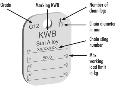
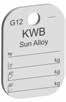
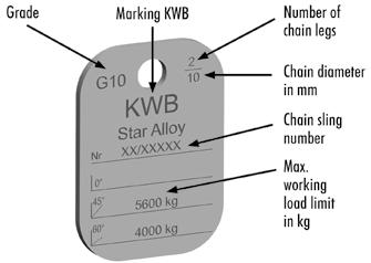
appropriate marking
chains & components
ISO 9OO1 certified company
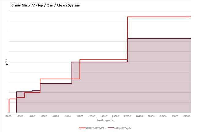
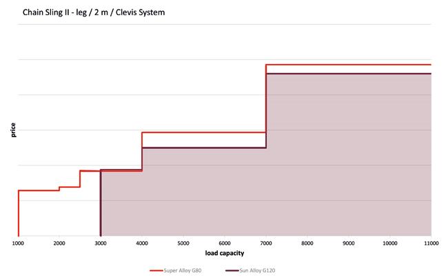
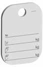
of experience Strong: 50 % higher load capacity compared to G 80, 20 % higher load capacity compared to G 100 e.g. 2-leg chain slings Light: Obvious weight reduction and censequently easier handling e.g. with 2-leg chain slings 3 m length Working Load Limit kg Previous Chain –Ø G 80 mm Sun Alloy-Chain –Ø mm 4,250 10 8 7,100 13 10 11,200 16 13 Working Load Limit kg Previous Chain Weight G 80 mm Sun Alloy-Chain Weight kg 4,250 11 7.5 7,100 19.6 12.9 11,200 31.2 22.4 Certificate A test certificate is issued for all our products which certifies all the specified charcteristics. Super Alloy G 80 Star Alloy G 100 Sun Alloy G 120 8 mm Load capacity 10 mm 13 mm 4.250 kg 11.200 kg 7.100 kg Super Alloy G 80 Sun Alloy G 120 Weight Clear Identification
of tag for ready made chain sling
Advantages
Durability:
Simple:
and
Traceability:
on
Quality:
Reliability: Decades
Sample
Economic: cheaper compared to G 80
Sun Alloy G 120 –the best answer for best quality.
7
Sun Alloy G 120 – Characteristics
N/mm2
N/mm2
Temperature -40° to 200 °C Load Factor Sun Alloy 1 Asymmetric Load Distribution In this case the working load limit must be reduced by at least one chain leg, for example a 3-leg or 4-leg sling is to be classified as a 2-leg chain sling. In case of doubt, it must be supposed that only one of the chain legs carries the entire load. Edge Loads R = larger than 2x chain Ø R = larger than chain Ø R = chain Ø or smaller
8
Load Factor 1 0.7 0.5 Impact Load slight impact medium impact strong impact Load Factor 1 0.7 impermissible
Chain Quality: Sun Alloy Chain SUN Corresponds with EN 818-2 & machinery directive 2006/42/EC Stress at Load Capacity Limit: 300 N/mm2 Test Stress: 750
– corresponds to 2.5 times the load capacity Breaking Stress: 1.200
– corresponds to 4 times the load capacity Breaking Elongation: min. 20 % Bending acc. to EN 818-2: 0.8 x nominal diameter Permissible Working Temperature: Sun Alloy Chain SUN max. 200 °C Components max. 200 °C Grade marking: Sun Alloy Chain SUN 12 Components 12 Surface: Sun Alloy Chain SUN Bordeaux Violet painted Components Bordeaux Violet powder coated Working Load Tag: All the required data is shown on the working load tag. Note: Working load tags should only be assembled acc. EN 818-4 and by competent persons. Working load tags should be used, solely when the respective chain & KWB components are assembled in the chain sling. Should alternative Working load limits arise in the chain sling through the use of special parts, the tags are impermissible. Disregard of these instructions can lead to material damage and personal injury. KWB will not assume liability.
9 Sun
–
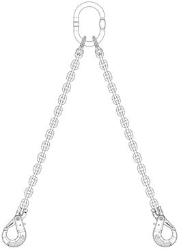
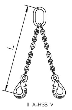
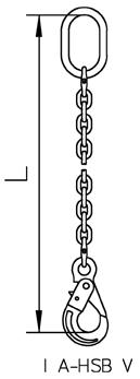
Examples I GTKR/SUN - HKSB/SUN I GTVK/SUN - HKS/SUN II GTKR/SUN - HKSB/SUN II GTVK/SUN - HKS/SUN IV GTKR/SUN - HKSB/SUN IV GTVK/SUN - HKS/SUN Example of Order Text: Chain Sun Alloy SUN 10 mm, 2 legs with Special Clevis Sub-Assembly GTKR/SUN and Clevis Sling Hook HKS/SUN, length 2,000 mm. SUN 10 II GTKR/SUN - HKS/SUN 2000 Chain Nominal diameter Number of legs Special Clevis Sub-Assembly Hook Length
Alloy G 120
the best answer for best quality. Sling


10 Sub-Assemblies 1-leg 2-leg Sun Alloy Chain Ø SUN Special Clevis Sub-Assembly GTVK/SUN 1 Special Clevis Sub-Assembly GTKR/SUN 1 Special Clevis Sub-Assembly GTVK/SUN 2 Special Clevis Sub-Assembly GTKR/SUN 2 mm inch Code Code Code Code 7 9/32 GTVK/SUN 1-7 GTKR/SUN 1-7 GTVK/SUN 2-7 GTKR/SUN 2-7 8 5/16 GTVK/SUN 1-8 GTKR/SUN 1-8 GTVK/SUN 2-8 GTKR/SUN 2-8 10 3/8 GTVK/SUN 1-10 GTKR/SUN 1-10 GTVK/SUN 2-10 GTKR/SUN 2-10 13 1/2 GTVK/SUN 1-13 GTKR/SUN 1-13 GTVK/SUN 2-13 GTKR/SUN 2-13 16 5/8 GTVK/SUN 1-16 GTKR/SUN 1-16 GTVK/SUN 2-16 GTKR/SUN 2-16 Page 11 Page 12 Page 12 Page 12 Page 13 Sling Hooks Sun Alloy Chain Ø SUN Clevis Self Locking Hook HKSB/SUN Clevis Sling Hook with forged Safety Latch HKS/SUN mm inch Code Code 7 9/32 HKSB/SUN 7 HKS/SUN 7 8 5/16 HKSB/SUN 8 HKS/SUN 8 10 3/8 HKSB/SUN 10 HKS/SUN 10 13 1/2 HKSB/SUN 13 HKS/SUN 13 16 5/8 HKSB/SUN 16 HKS/SUN 16 Page 11 Page 13 Page 13 Sub-Assemblies 3 & 4-leg Sun Alloy Chain Ø SUN Special Clevis Sub-Assembly GTVK/SUN 4 Special Clevis Sub-Assembly GTKR/SUN 4 mm inch Code Code 7 9/32 GTVK/SUN 4-7 GTKR/SUN 4-7 8 5/16 GTVK/SUN 4-8 GTKR/SUN 4-8 10 3/8 GTVK/SUN 4-10 GTKR/SUN 4-10 13 1/2 GTVK/SUN 4-13 GTKR/SUN 4-13 16 5/8 GTVK/SUN 4-16 GTKR/SUN 4-16 Page 11 Page 12 Page 13

11 Sun
G 120 –the best
for best quality. Chain Sun Alloy SUN – Measurements, Load Values, Weights Chain D Pitch P Li/min. Le/max. Weight Working Load limit Breaking Load mm inch mm mm mm kg/m kg kN
Sun Alloy Chain Maximum Working Load Limit for Sun Alloy Chains Safety factor 1-leg Chains 2-leg Chains 3- and 4-leg Chains 4 Angle of Inclination - - up to 45° 45°-60° up to 45° 45°-60° up to 45° 45°-60° Load Factor 1 0.8 1.4 1 1.12 0.8
1.5 Ø Load Capacity [kg]
Alloy
answer
7 9/32 21 9.8 26.0 1.33 2,360 92.6 8 5/16 24 11.0 30.5 1.59 3,000 118 10 3/8 30 14.3 38.0 2.66 5,000 196 13 1/2 39 18.0 48.5 4.43 8,000 319 16 5/8 48 21.5 59.0 6.73 12,200 479
2.1
7 2,360 1,900 3,350 2,360 2,650 1,900 5,000 3,550 8 3,000 2,360 4,250 3,000 3,350 2,360 6,300 4,500 10 5,000 4,000 7,100 5,000 5,600 4,000 10,600 7,500 13 8,000 6,300 11,200 8,000 9,000 6,300 17,000 11,800 16 12,200 9,700 17,000 12,200 13,600 9,700 25,600 18,300 If the chain slings are used in more demanding conditions (e.g. high temperature, asymmetric load distribution, edge loads, impacts) the maximum load capacities in the table must be reduced. Please use the load factors on page 8 and refer to the specification in the user information.
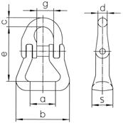
12 4 Special Clevis Sub-Assembly GTVK/SUN Chain Ø Code Can be used to single hook acc, to DIN15401 no. Dimensions Weight Working Load Limit ß d t w e up to 45° 45°-60° mm inch mm kg kg kg 7 9/32 GTVK/SUN 4-7 10 27 190 110 368 6.35 5,000 3,550 8 5/16 GTVK/SUN 4-8 10 27 190 110 368 6.39 6,300 4,500 10 3/8 GTVK/SUN 4-10 12 30 190 110 433 10.94 10,600 7,500 13 1/2 GTVK/SUN 4-13 12 38 275 150 616 25.35 17,000 11,800 16 5/8 GTVK/SUN 4-16 12 38 275 150 658 37.17 25,600 18,300 For 3 and 4-leg slings with shortening element. 1 Special Clevis Sub-Assembly GTKR/SUN Chain Ø Code Can be used to single hook acc. to DIN15401 no. Dimensions Weight Working Load Limit d t w e mm inch mm kg kg 7 9/32 GTKR/SUN 1-7 4 14 120 70 163 0.66 2,360 8 5/16 GTKR/SUN 1-8 5 17 140 80 183 0.92 3,000 10 3/8 GTKR/SUN 1-10 6 19 160 95 211 1.55 5,000 13 1/2 GTKR/SUN 1-13 10 27 190 110 254 3.34 8,000 16 5/8 GTKR/SUN 1-16 12 30 190 110 268 4.92 12,200 For 1-leg slings. 1 Special Clevis Sub-Assembly GTVK/SUN Chain Ø Code Can be used to single hook acc. to DIN15401 no. Dimensions Weight Working Load Limit d t w e mm inch mm kg kg 7 9/32 GTVK/SUN 1-7 4 14 120 70 244 1.22 2,360 8 5/16 GTVK/SUN 1-8 5 17 140 80 264 1.48 3,000 10 3/8 GTVK/SUN 1-10 6 19 160 95 318 2.63 5,000 13 1/2 GTVK/SUN 1-13 10 27 190 110 391 6.11 8,000 16 5/8 GTVK/SUN 1-16 12 30 190 110 423 8.90 12,200 For 1-leg slings with shortening element. Sub-Assemblies 2 Special Clevis Sub-Assembly GTVK/SUN Chain Ø Code Can be used to single hook acc, to DIN15401 no. Dimensions Weight Working Load Limit ß d t w e up to 45° 45°-60° mm inch mm kg kg kg 7 9/32 GTVK/SUN 2-7 6 19 160 95 284 2.62 3,350 2,360 8 5/16 GTVK/SUN 2-8 6 19 160 95 284 2.64 4,250 3,000 10 3/8 GTVK/SUN 2-10 10 23 170 105 328 4.83 7,100 5,000 13 1/2 GTVK/SUN 2-13 10 30 190 110 391 10.54 11,200 8,000 16 5/8 GTVK/SUN 2-16 12 38 275 150 508 18.33 17,000 12,200 For 2-leg slings with shortening element.
13 Sun Alloy G 120 –the best answer for best quality. 2 Special Clevis Sub-Assembly GTKR/SUN Chain Ø Code Can be used to single hook acc, to
no. Dimensions Weight Working Load Limit ß d t w e up
mm inch mm kg
7
GTKR/SUN
6
8
6
10
10
13
10
16
12
For 2-leg slings. 4 Special Clevis Sub-Assembly GTKR/SUN Chain Ø Code Can be used to single hook acc, to
no. Dimensions Weight Working Load Limit ß d t w e up
mm inch mm kg kg kg 7
GTKR/SUN
10
8
10
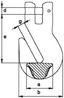
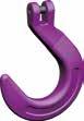
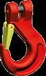
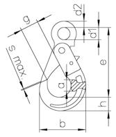
10 3/8 GTKR/SUN 4-10 12 30 190 110 326 6.62 10,600 7,500 13 1/2 GTKR/SUN 4-13 12 38 275 150 479 14.27 17,000 11,800 16 5/8 GTKR/SUN 4-16 12 38 275 150 503 21.25 25,600 18,300 For 3 and 4-leg slings. Clevis Self Locking Hook HKSB/SUN Chain Code Dimensions Weight Working Load Limit e h a b d g s max. mm inch mm kg kg 7 9/32 HKSB/SUN 7 125 26 21 92 9,5 32 1 0.94 2,360 8 5/16 HKSB/SUN 8 124 26 21 92 11 32 1 0.95 3,000 10 3/8 HKSB/SUN 10 143 31 26 115 14 45 1 1.91 5,000 13 1/2 HKSB/SUN 13 183 42 35 145 17,5 54 2 3.66 8,000 16 5/8 HKSB/SUN 16 218 51 41 169 21 60 2 6.80 12,200 Closes and locks automatically. Clevis Sling Hook with Forged Safety Latch HKS/SUN Chain Code Dimensions Weight Working Load Limit e h a b d g1 mm inch mm kg kg 7 9/32 HKS/SUN 7 93 27 21 89 9,5 26 0.67 2,360 8 5/16 HKS/SUN 8 92 27 21 89 11 26 0.67 3,000 10 3/8 HKS/SUN 10 108 33 25 110 14 31 1.23 5,000 13 1/2 HKS/SUN 13 130 41 34 132 17,5 38 2.42 8,000 16 5/8 HKS/SUN 16 158 49 37 160 21 45 4.22 12,200 General purpose hook. Sling Hooks
DIN15401
to 45° 45°-60°
kg kg
9/32
2-7
19 160 95 203 1.50 3,350 2,360
5/16 GTKR/SUN 2-8
19 160 95 203 1.52 4,250 3,000
3/8 GTKR/SUN 2-10
23 170 105 221 2.67 7,100 5,000
1/2 GTKR/SUN 2-13
30 190 110 257 5.00 11,200 8,000
5/8 GTKR/SUN 2-16
38 275 150 353 10.37 17,000 12,200
DIN15401
to 45° 45°-60°
9/32
4-7
27 190 110 287 4.11 5,000 3,550
5/16 GTKR/SUN 4-8
27 190 110 287 4.15 6,300 4,500
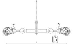
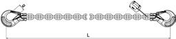
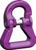
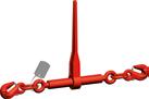
14 SUN Alloy lashing Load Binder RLSP/SUN Code Marking/ Stamping LC Lashing capacity [kN] STF Standard tension force [daN] Length L closed [mm] Length L opened [mm] Tension distance [mm] Lever length l [mm] Jaw opening g [mm] Weight [kg/pc.] RLSP/SUN 8 Type A 60 1.900 473 615 140 237 10 4,30 RLSP/SUN 10 Type B 100 3.000 504 657 140 355 13 6,20 RLSP/SUN 13 Type C 160 2.500 765 1.054 290 359 16 13,30 Lashing chain ZK/SUN Code LC Lashing capacity [kN] Lenght L [mm] Jaw opening g [mm] Weight [kg/pc.] ZK/SUN 8 60 3.500 26 6,90 ZK/SUN 10 100 3.500 31 11,10 ZK/SUN 13 160 3.500 38 19,10
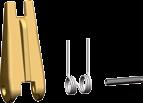

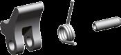

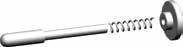
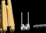
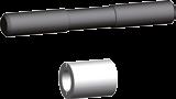
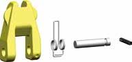
15 Sun Alloy G 120 –the best answer for best quality. Spare Parts Forged Safety Latch Kits for Clevis Sling Hooks Dimension Code Spare Part for mm inch 7+8 9/32+5/16 FG/SUN 7/8 HKS/SUN 7, HKS/SUN 8 10 3/8 FG/SUN 10 HKS/SUN 10 13 1/2 FG/SUN 13 HKS/SUN 13 16 5/8 FG/SUN 16 HKS/SUN 16 Pin Kit for Clevis Self Locking Hook & Special Clevis Sub Assembly Dimension Code Accessory for use mm inch 7 9/32 KBG/SUN 7 HKS/SUN 7, HKSB/SUN 7, GTVK/SUN ..-7, GTKR/SUN ..-7 8 5/16 KBG/SUN 8 HKS/SUN 8, HKSB/SUN 8, GTVK/SUN ..-8, GTKR/SUN ..-8 10 3/8 KBG/SUN 10 HKS/SUN 10, HKSB/SUN 10, GTVK/SUN ..-10, GTKR/SUN ..-10 13 1/2 KBG/SUN 13 HKS/SUN 13, HKSB/SUN 13, GTVK/SUN ..-13, GTKR/SUN ..-13 16 5/8 KBG/SUN 16 HKS/SUN 16, HKSB/SUN 16, GTVK/SUN ..-16, GTKR/SUN ..-16 Trigger Kit for Clevis Self Locking Hooks Dimension Code Spare Part for mm inch 7+8 9/32+5/16 HBG/SUN 7/8 HKSB/SUN 7 + HKSB/SUN 8 10 3/8 HBG/SUN 10 HKSB/SUN 10 13 1/2 HBG/SUN 13 HKSB/SUN 13 16 5/8 HBG/SUN 16 HKSB/SUN 16 Working Load Tag with Wire Rope Binder and Fastener Code Code ID-Set 1/2/3/4-legs Safety Catch Kit for Eye Grab Hook with Safety Pin PGS/SUN Chain Code Spare Part for mm inch 7+8 9/32+5/16 PGS/SUN 7/8 PS/SUN 7/8 10 3/8 PGS/SUN 10 PS/SUN 10 13 1/2 PGS/SUN 13 PS/SUN 13

Content Star Alloy Grade 100 17 Advantages Star Alloy G 1OO 18 Characteristics of Star Alloy G 1OO 19 Sling Examples 20-21 Synoptical Table of Available Products 22-23 Star Alloy Chain and Star Alloy Plus+/PAS Chain 24 Star Alloy G 1OO Working Load Limits 24 Master Links, Sub-Assemblies & Accessories 25-31 Special Accessoires 32 Spare Parts 33-34
Advantages of Star Alloy G 100
Safe: with the violet signal colour no risk of confusion with G 80
Durability: higher wear resistance due to increased hardness
Simple: easily adjustable with multi-function shortening hook
Traceability: appropriate marking on chains & components
Quality: ISO 9OO1 certified company

Reliability: Decades of experience
Strong: 25 % higher load capacity than G 80 allows the transition to smaller chain diameters e.g. 2-leg chain slings
Working Load Limit kg Previous Chain – Ø G 80 mm Star Alloy-Chain – Ø mm 3,550 10 8 5,600 13 10 9,000 16 13
Light: with smaller chain dimensions considerable weight reduction compared to G-80, easier handling e.g. with 2-leg chain slings 3 m length
Working Load Limit kg Previous Chain Weight G 80 mm Star Alloy-Chain Weight kg 3,550 16.2 11.0 5,600 27.6 17.6 9,000 42.2 29.6
Clear
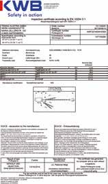
Certificate
18
Identification
A test certificate is issued for all our products which certifies all the specified characteristics.
Sample of tag for ready made chain sling
Star Alloy G 100 – Characteristics
Chain Quality:
Star Alloy SA/S Corresponds with ASTM A973/A973M-01 & EN 818-2 but with higher working load limit (permissible operating temperature max. 200° C) & machinery directive 2006/42/EC
Star Alloy Plus PAS SAPP/S Corresponds with PAS 1061 & machinery directive 2006/42/EC
Star Alloy Plus + SAP/S Corresponds with EN 818-2 with a higher load capacity & machinery directive 2006/42/EC
Stress at Load Capacity Limit: 250 N/mm2

Test Stress: 625 N/mm2 corresponds to 2.5 times the load capacity
Breaking Stress: 1,000 N/mm2 corresponds to 4 times the load capacity Breaking Elongation: min. 20 % Bending acc. to PAS 1061/EN 818-2: 0.8 x nominal diameter
Permissible Working Temperature:
Grade Marking:
Star Alloy SA/S max. 200 °C
Star Alloy Plus + SAP/S max. 380 °C
Star Alloy Plus PAS SAPP/S max. 380 °C Components max. 380 °C
Star Alloy SA/S 10 at a spacing of approx. 300 mm up to dim. 16 (others 900 mm) and 10 on the back of each link
Star Alloy Plus + SAP/S 8S at a spacing of approx. 900 mm up from dim. 19 Star Alloy Plus PAS SAPP/S 10 at a spacing of approx. 300 mm up to dim. 16 Components 10 (some components are still marked with 8S)
Surface: Star Alloy SA/S Purple varnished Star Alloy Plus + SAP/S Violet varnished Star Alloy Plus PAS SAPP/S Violet varnished Components Violet powder coated
Working Load Tag:
Star Alloy
Alloy Plus PAS/ Star Alloy Plus+
The performance concerning stress crack corrosion is identical to G 80
Temperature -40° to 200 °C above 200° to 300 °C above 300° to 380 °C
Load Factor Star Alloy 1 impermissible impermissible
Load Factor Star Alloy Plus+/PAS 1 0.9 0.75
Asymmetric Load Distribution
In this case the working load limit must be reduced by at least one chain leg, for example a 3-leg or 4-leg sling is to be classified as a 2-leg chain sling. In case of doubt, it must be supposed that only one of the chain legs carries the entire load.
Edge Loads R = larger than 2x chain Ø R = larger than chain Ø R = chain Ø or smaller
Load Factor 1 0.7 0.5
Impact Load slight impact medium impact strong impact Load Factor 1 0.7 impermissible

Star Alloy G 100 –whenever 100 % is required, the best answer is to trust in a star.

19
and by
be used solely when the particular chain &
components are assembled in the
sling.
alternative
the
sling
these instructions can lead to material damage and personal injury.
will not
Star
All the required data is shown on the working load tag. Note: Working load tags should only be assembled acc. EN 818-4
competent persons. Working load tags can
KWB
chain
Should
Working load limits arise in
chain
through the use of special parts, the tags are impermissible. Disregard of
KWB
assume liability.
20
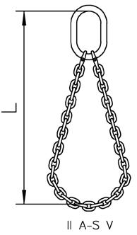
Examples I A/S-HS/S V/S I HS/S-HS/S V/S I A/S-HSB/S V/S I GTVK/S-HKSB/S I A/S-P/S V/S II A/S-HS/S V/S II A/S-HSB/S V/S II A/S-HS/S-P/S V/S II GTVK/S-HKSB/S II GTVK/S-HS/S V/S II A/S-S V/S
Sling
21 Star
–
IV G/S-S V/S IV G/S-HS/S V/S IV GTVK/S-HS/S V/S IV GTVKS/S-HKSB/S Example of Order Text: Chain Star Alloy SA/S 10 mm, 2 legs with Masterlink A/S and Eye Sling Hook with Forged Safety Latch HS/S, length 3,000 mm assembled with Connecting Link V/S. SA/S 10 II A/S - HS/S 3000 V/S Chain Nominal diameter Number of legs Master Link Hook Length Connecting link
Alloy G 100
whenever 100 % is required, the best answer is to trust in a star.


22 Master Links & Sub-Assemblies 1-leg Chain Star Alloy Chain Star Alloy Plus PAS Chain Star Alloy Plus+Ø Master Link A/S Special Master Link T/S Special Master Link Assembly GL/S Special Clevis Sub-Assembly
mm inch Code Code Code Code 6 1/4 A/S 13 T/S 13
7 9/32 A/S 13 T/S 13
8 5/16 A/S 16 T/S 16
10 3/8 A/S 18 T/S 18 GL/S
13 1/2 A/S 22 T/S 22 GL/S
16 5/8 A/S 26 T/S 26 GL/S
19 3/4 A/S 32 T/S 32 GL/S
22 7/8 A/S 36 T/S 36 GL/S
26 1 A/S 45 Page 24 Page 25 Page 25 Page 26 Page 27 Master Links & Sub-Assemblies 2-leg Chain Star Alloy Chain Star Alloy Plus PAS Chain Star Alloy Plus+Ø Master Link A/S Special Master Link T/S Special Master Link Assembly GL/S Special Clevis Sub-Assembly
mm inch Code Code Code Code 6 1/4 A/S 13 T/S 13 GL/S 2-6/7/8/4-6 GTVK/S 2-6 7 9/32 A/S 16 T/S 16 GL/S 2-6/7/8/4-6 GTVK/S 2-7 8 5/16 A/S 18 T/S 18 GL/S 2-6/7/8/4-6 GTVK/S 2-8 10 3/8 A/S 22 T/S 22 GL/S 2-10/4-7/8 GTVK/S 2-10 13 1/2 A/S 26 T/S 26 GL/S 2-13/4-10 GTVK/S 2-13 16 5/8 A/S 32 T/S 32 GL/S 2-16/4-13 GTVK/S 2-16 19 3/4 A/S 36 T/S 36 GL/S 2-19/4-16 22 7/8 A/S 45 26 1 A/S 50 T/S 56 Page 24 Page 25 Page 25 Page 26 Page 27 Master Links & Sub-Assemblies 3 & 4-leg Chain Star Alloy Chain Star Alloy Plus PAS Chain Star Alloy Plus+Ø Sub-Assembly G/S Special Sub-Assembly GT/S Special Sub-Assembly TG/S Special Sub-Assembly GL/S Special Clevis Sub-Assembly GTVK/S 4 mm inch Code Code Code Code Code 6 1/4 G/S 6 GT/S 6 TG/S 6 GL/S 2-6/7/8/4-6 GTVK/S 4-6 7 9/32 G/S 7/8 GT/S 7/8 TG/S 7/8 GL/S 2-10/4-7/8 GTVK/S 4-7 8 5/16 G/S 7/8 GT/S 7/8 TG/S 7/8 GL/S 2-10/4-7/8 GTVK/S 4-8 10 3/8 G/S 10 GT/S 10 TG/S 10 GL/S 2-13/4-10 GTVK/S 4-10 13 1/2 G/S 13 GT/S 13 TG/S 13 GL/S 2-16/4-13 GTVK/S 4-13 16 5/8 G/S 16 GT/S 16 TG/S 16 GL/S 2-19/4-16 GTVK/S 4-16 19 3/4 G/S 19/20 22 7/8 G/S 22 26 1 G/S 26 Page 24 Page 25 Page 26 Page 26 Page 26 Page 27
GTVK/S 1
GTVK/S 1-6
GTVK/S 1-7
GTVK/S 1-8
1-10 GTVK/S 1-10
1-13 GTVK/S 1-13
1-16 GTVK/S 1-16
1-19/22
1-19/22
GTVK/S 2


23 Star Alloy G 100 –whenever 100 % is required, the
answer
a star. Connecting & Shortening Elements Chain Star Alloy Chain Star Alloy Plus PAS Chain Star Alloy Plus+Ø Connecting Link V/S Webbing Coupling Link RSK/S Shortening Hook VK/S Eye Grab Hook P/S Eye Grab Hook with Safety Pin PS/S Clevis Grab Hook PK/S mm inch Code Code Code Code Code Code 6 1/4 V/S 6 VK/S 6 P/S 6 PK/S 6 7 9/32 V/S 7 VK/S 7 P/S 7/8 PS/S 7/8 PK/S 7 8 5/16 V/S 8 RSK/S 8 VK/S 8 P/S 7/8 PS/S 7/8 PK/S 8 10 3/8 V/S 10 RSK/S 10 VK/S 10 P/S 10 PS/S 10 PK/S 10 13 1/2 V/S 13 RSK/S 13 VK/S 13 P/S 13 PS/S 13 PK/S 13 16 5/8 V/S 16 RSK/S 16 VK/S 16 P/S 16 PK/S 16 19 3/4 V/S 19/20 P/S 19/20 PK/S 19/20 22 7/8 V/S 22 RSK/S 22 P/S 22 PK/S 22 26 1 V/S 26 P/S 26 Page 24 Page 28 Page 28 Page 28 Page 29 Page 29 Page 29 Sling Hooks Chain Star Alloy Chain Star Alloy Plus PAS Chain Star Alloy Plus+Ø Clevis Sling Hook with Forged Safety Latch HKS/S Clevis Self Locking Hook HKSB/S Clevis Foundry Hook GHK/S Eye Sling Hook with Forged Safety Latch HS/S Eye Self Locking Hook HSB/S Swivel Safety Hook WSB/S Foundry Hook GH/S mm inch Code Code Code Code Code Code Code 6 1/4 HKS/S 6 HKSB/S 6 HS/S 6 HSB/S 6 WSB/S 6 7 9/32 HKS/S 7 HKSB/S 7 HS/S 7/8 HSB/S 7/8 WSB/S 7/8 GH/S 7/8 8 5/16 HKS/S 8 HKSB/S 8 GHK/S 8 HS/S 7/8 HSB/S 7/8 WSB/S 7/8 GH/S 7/8 10 3/8 HKS/S 10 HKSB/S 10 GHK/S 10 HS/S 10 HSB/S 10 WSB/S 10 GH/S 10 13 1/2 HKS/S 13 HKSB/S 13 GHK/S 13 HS/S 13 HSB/S 13 WSB/S 13 GH/S 13 16 5/8 HKS/S 16 HKSB/S 16 HS/S 16 HSB/S 16 WSB/S 16 GH/S 16 19 3/4 HKS/S 19/20 HS/S 19/20 HSB/S 19/20 GH/S 19/20 22 7/8 HKS/S 22 HS/S 22 HSB/S 22 26 1 HS/S 26 Page 24 Page 30 Page 30 Page 30 Page 31 Page 31 Page 31 Page 31 Special Accessories Chain Star Alloy Chain Star Alloy Plus PAS Chain Star Alloy Plus+Ø Sheet Metal Plate Hook BH/S Ratchet Load Binder RLS/S mm inch Code Code 6 1/4 7 9/32 BH/S 7/8 8 5/16 BH/S 7/8 RLS/S 8 10 3/8 BH/S 10 RLS/S 10 13 1/2 BH/S 13 RLS/S 13 16 5/8 BH/S 16 19 3/4 BH/S 19/20 22 7/8 BH/S 22 26 1 Page 24 Page 32 Page 32
best
is to trust in


24 Chain Star Alloy SA/S – Measurements, Load Values, Weights Chain D Pitch P Li/min. Le/max. Weight Working Load limit Breaking Load mm inch mm mm mm kg/m kg kN 6
Chain acc. ASTM A973/A973M-01 Chain Star Alloy Plus PAS SAPP/S - Chain Star Alloy Plus+ SAP/S –Measurements, Load Values, Weights Chain D Pitch P Li/min. Le/max. Weight Working Load Limit Breaking Load mm inch mm mm mm kg/m kg kN 6
18
22 0.96
7
36
13
39
47
16
19
57
22
Dimension 6 to 16 acc. PAS 1061 (SAPP/S). Dimension 19 to 26 acc. EN 818-2 with higher working load limit (SAP/S). Maximum Working Load Limit for Star Alloy Chains Safety factor 1-leg Chains 2-leg Chains 3- and 4-leg Chains 4 Angle of Inclination - - up to 45° 45°-60° up to 45° 45°-60° up to 45° 45°-60° Load Factor 1 0.8 1.4 1 1.12 0.8 2.1 1.5 Ø Load Capacity [kg] 6 1,400 1,120 2,000 1,400 1,600 1,120 3,000 2,120 7 1,900 1,500 2,650 1,900 2,120 1,500 4,000 2,800 8 2,500 2,000 3,550 2,500 2,800 2,000 5,300 3,750 10 4,000 3,150 5,600 4,000 4,250 3,150 8,000 6,000 13 6,700 5,300 9,500 6,700 7,500 5,300 14,000 10,000 16 10,000 8,000 14,000 10,000 11,200 8,000 21,200 15,000 19 14,000 11,200 20,000 14,000 16,000 11,200 30,000 21,200 22 19,000 15,000 26,500 19,000 21,200 15,000 40,000 28,000 26 26,500 21,200 37,500 26,500 30,000 21,200 56,000 40,000 If the chain slings are used in more demanding conditions (e.g. high temperature, asymmetric load distribution, edge loads, impacts) the maximum load capacities in the table must be reduced. Please use the load factors on page 19 and refer to the specification in the user information. Star Alloy Chain and Star Alloy Plus+/PAS Chain
1/4 18 8,7 22 0.96 1,400 56.5 7 9/32 21 9,5 25 1.20 1,900 77 8 5/16 24 10,9 29 1.57 2,500 101 10 3/8 30 13,5 36 2.46 4,000 157 13 1/2 39 17,5 47 4.18 6,700 265 16 5/8 48 21,5 58 6.28 10,000 402 19 3/4 57 26,6 69 8.90 14,000 567 22 7/8 66 29,5 79 11.88 19,000 760 26 1 78 35 94 16.18 26,500 1,060
1/4
8,7
1,400 56.5
9/32 21 9,5 25 1.20 1,900 77 8 5/16 24 10,9 29 1.57 2,500 101 10 3/8 30 13,5
2.46 4,000 157
1/2
17,5
4.18 6,700 265
5/8 48 21,5 58 6.28 10,000 402
3/4
26,6 69 8.90 14,000 567
7/8 66 29,5 79 11.88 19,000 760 26 1 78 35 94 16.18 26,500 1,060
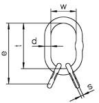
Master Link A/S
Special Master Link T/S
Similar to master link A/S, but due to larger inside dimensions suitable for next sized crane hook or special hook.

Chain Ø Code Can be used to single hook acc. to DIN15401 no.
Dimensions
Weight Working Load Limit 0°-45° *) d t w s mm mm mm kg kg
6+7 6 A/S 13 2.5 13 110 60 10 0.34 2,300 8 7 A/S
Chain Ø Code Can be used to single hook acc. to DIN15401 no.
Dimensions
Weight Working Load Limit 0°-45° *) d t w s mm mm mm kg kg
6+7 6 T/S 13 4 14 120 70 10 0.46 2,300 8 7 T/S 16 5 16 140 80 13 0.73 3,200 10 8 T/S 18 6 19 160 95 14 1.12 4,200 13 10 T/S 22 10 23 170 105 17 1.81 6,700 16 13 T/S 26 10 27 190 110 20 2.72 10,100 19 16 T/S 32 12 33 230 130 26 4.78 16,000 22 19 T/S 36 20 38 275 150 29 7.48 21,200 26 T/S 56 50 56 350 250 21.98 40,000
*) Please refer to table „Maximum working load Limit“ on page 24 when using in chain slings.
100 –whenever 100 % is required, the best answer is to trust in a star.
25 Star Alloy G
16 2.5 17 110 60 14 0.55 3,500 10 8 A/S 18 5 19 135 75 14
13 10 A/S 22 6 23 160 90 17
16 13 A/S
8 27 180 100 20
19 16 A/S
10 33
110
22 19
16 36
140
26 22 A/S 45 25 45 340 180
26 A/S 50 32 50 350 190
40,000 A/S 56 32 56 400 200 23.3 64,000 *) Please refer to table „Maximum working load Limit“ on page 24 when using in chain slings. Sub-Assembly G/S Chain Ø Code Can be used to single hook acc. to DIN15401 no. Dimensions Weight Working Load Limit 0°-45° *) e d t w d1 t1 w1 s mm mm kg kg 6 G/S 6 5 189 19 135 75 13 54 25 10 1.28 4,200 7+8 G/S 7/8 6 230 23 160 90 17 70 34 14 2.37 7,600 10 G/S 10 8 265 27 180 100 20 85 40 14 3.75 9,600 13 G/S 13 10 315 33 200 110 23 115 50 17 6.60 14,000 16 G/S 16 16 400 36 260 140 27 140 65 20 10.06 21,200 19 G/S 19/20 32 500 50 350 190 33 150 70 26 22.87 34,100 22 G/S 22 32 520 50 350 190 36 170 75 24.79 40,000 26 G/S 26 32 570 56 400 200 45 170 80 37.60 56,000 *) Please refer to table „Maximum working load Limit“ on page 24 when using in chain slings. Master Links, Sub-Assemblies & Accessories
0.94 5,000
1.64 7,600
26
2.53 10,000
32
200
26 4.28 14,000
A/S 36
260
6.22 25,100
12.74 30,800
16.55
Special


26
TG/S Chain Ø Code Can be used to
Dimensions Weight
0°-45°
d e t w d1 mm mm kg kg 6
5
7+8
13
Please
are
AS-link AS-link
Sub-Assembly GT/S Chain Ø Code Can be used to single hook acc. to
no. Dimensions Weight Working Load
0°-45° *) e d t w d1 t1 w1 s mm mm kg kg 6 GT/S
6 214 19 160 95 13 54 25 10
7+8
10
170
17
10
10
27 190 110
13
12
33 230 130 23 115 50 17 7.21 15,700 16 GT/S 16 25 415 38 275 150 27 140 65 20 11.30 21,200 *) Please refer to table „Maximum working load Limit“ on page 24 when using in chain slings. Similar to G/S but also suitable for larger crane hooks and special hooks. Special Master Link Assembly GL/S Chain Ø Code Consisting of Dimensions Can be used to single hook acc. to DIN15401 no. Weight Working Load Limit 0°-45° d t w e mm mm mm mm kg kg 10 GL/S 1-10 L/S27+B/S16 27 340 180 410 25 4.76 4,000 13 GL/S 1-13 L/S27 27 340 180 340 25 4.40 6,700 16 GL/S 1-16 L/S32 33 340 180 340 25 6.70 10,000 19+22 GL/S 1-19/22 L/S40 40 340 180 340 25 10.00 19,000 0°-45°* 6+7+8 6 GL/S 2-6/7/8/4-6 L/S 22+2B/S13 23 340 180 394 25 3.54 3,550 10 7+8 GL/S 2-10/4-7/8 L/S 27+2B/S16 27 340 180 410 25 5.12 5,600 13 10 GL/S 2-13/4-10 L/S 32+2B/S20 33 340 180 425 25 7.92 9,500 16 13 GL/S 2-16/4-13 L/S 40+2B/S22 40 340 180 455 25 12.32 14,000 19 16 GL/S 2-19/4-16 L/S 40+2B/S26 40 340 180 480 25 13.84 21,200 GL/S 1 GL/S 2
Sub-Assembly
single hook acc. to DIN15401 no.
Working Load Limit
*)
TG/S 6
19 245 135 75 13 1.63 3,000
TG/S 7/8 6 23 270 160 90 16 2.73 5,300 10 TG/S 10 10 33 360 200 110 23 7.45 10,100
TG/S 13 16 36 440 260 140 27 11.14 14,300 16 TG/S 16 25 45 540 340 180 33 21.02 22,200 *)
refer to table „Maximum working load Limit“ on page 24 when using in chain slings. For 4-leg slings, when shortening hooks
to be assembled seperately, and for slings with thimbled eyes.
Special
DIN15401
Limit
6
1.47 4,200
GT/S 7/8
240 23
105
70 34 14 2.53 6,600
GT/S 10
275
20 85 40 14 3.87 10,100
GT/S 13
345
1 Special Clevis Sub-Assembly GTVK/S
For 1-leg slings with shortening element.
Ø Code Can be used to single hook acc. to DIN15401 no.
Chain
Dimensions
Weight Working Load Limit d t w e mm inch mm kg kg 6 1/4 GTVK/S 1-6 4 14 120 70 204 0.68 1,400 7 9/32 GTVK/S 1-7 4 14 120 70 242 1.12 1,900 8 5/16 GTVK/S 1-8 5 16 140 80 262 1.37 2,500 10 3/8 GTVK/S 1-10 6 19 160 95 319 2.45 4,000 13 1/2 GTVK/S 1-13 10 23 170 105 373 4.65 6,700 16 5/8 GTVK/S 1-16 10 27 190 110 424 8.05 10,000
2 Special Clevis Sub-Assembly GTVK/S
Dimensions Weight Working Load Limit ß d t w e up to 45° 45°-60° mm inch mm kg kg kg 6 1/4 GTVK/S 2-6 4 14 120 70 204 0.89 2,000 1,400 7 9/32 GTVK/S 2-7 5 16 140 80 262 2.03 2,650 1,900 8 5/16 GTVK/S 2-8 6 19 160 95 282 2.48 3,550 2,500 10 3/8 GTVK/S 2-10 10 23 170 105 329 4.44 5,600 4,000 13 1/2 GTVK/S 2-13 10 27 190 110 393 8.17 9,500 6,700 16 5/8 GTVK/S 2-16 12 33 230 130 464 15.13 14,000 10,000 For
4
Chain Ø Code Can be used to single hook acc, to DIN15401 no.
100 –whenever 100 % is required, the best answer is to trust in a star.
27 Star Alloy G
2-leg slings with shortening element.
Special Clevis Sub-Assembly GTVK/S Chain Ø Code Can be used to single hook acc, to DIN15401 no. Dimensions Weight Working Load Limit ß d t w e up to 45° 45°-60° mm inch mm kg kg kg 6
6
7
8
10
13
12
16
For 3 and 4-leg slings with shortening element.
1/4 GTVK/S 4-6
19 160 95 298 2.40 3,000 2,120
9/32 GTVK/S 4-7 10 23 160 110 352 5.18 4,000 2,800
5/16 GTVK/S 4-8 10 23 170 105 362 5.25 5,300 3,750
3/8 GTVK/S 4-10 10 27 190 110 434 9.04 8,000 6,000
1/2 GTVK/S 4-13
33 230 130 548 18.15 14,000 10,000
5/8 GTVK/S 4-16 20 38 275 150 649 31.99 21,200 15,000


28 Connecting Link V/S Chain Code Dimensions Weight Working Load Limit e c s d b g mm inch mm kg kg 6 1/4 V/S 6 44 8 11 8 39 14 0.11 1,400 7 9/32 V/S 7 51 10 13 9 47 17 0.20 1,900 8 5/16 V/S 8 62 12 14 10 55 18 0.29 2,500 10 3/8 V/S 10 72 15 18 13 64 24 0.52 4,000 13 1/2 V/S 13 88 20 22 17 79 28 0.91 6,700 16 5/8 V/S 16 103 21 29 21 106 33 1.34 10,000 19/20 3/4 V/S 19/20 115 30 35 24 123 42 3.33 16,000 22 7/8 V/S 22 161 34 39 25 148 51 3.14 19,000 26 1 V/S 26 190 40 46 30 175 60 5.72 26,500 Connecting link for: Master Link – Chain Chain – Chain Hook – Chain Only for straight pull! Load pin and bush are also seperately available. Webbing Coupling Link RSK/S Chain Code Dimensions Weight Working Load Limit a e c d b s g mm inch mm kg kg 8 5/16 RSK/S 8 29 66 12 10 68 18 18 0.36 2,500 10 3/8 RSK/S 10 40 81 15 13 82 21 24 0.69 4,000 13 1/2 RSK/S 13 44 104 20 17 101 28 28 1.32 6,700 16 5/8 RSK/S 16 47 113 21 21 110 40 33 1.83 10,000 22 7/8 RSK/S 22 110 190 34 25 215 58 51 7.98 19,000 Link for webbing slings mounted in one V/S-half. Reduced risk of damage due to wide surface. Shortening Hook VK/S Chain Code Dimensions Weight Working Load Limit e b a d1 d2 g mm inch mm kg kg 6 1/4 VK/S 6 84 37 29 18 9 8 0.27 1,400 7 9/32 VK/S 7 122 54 39 24 12 11 0.67 1,900 8 5/16 VK/S 8 122 54 39 24 12 11 0.67 2,500 10 3/8 VK/S 10 159 70 50 31 14 13 1.34 4,000 13 1/2 VK/S 13 203 92 64 37 18 15 2.83 6,700 16 5/8 VK/S 16 234 102 80 48 24 20 5.43 10,000 Can be mounted in any chain leg due to Clevis part. No WLL reduction.
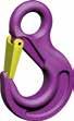
Eye Grab Hook P/S
For shortening and for any slings that must not tighten.
Reduction of load capacity not required due to 4-fold safety.
Weight Working Load Limit e b d1 d2 g a
mm inch mm kg kg
6 1/4 P/S 6 * 50 42 12 9 7 26 0.15 1,400
7+8 9/32+5/16 P/S 7/8 * 65 56 16 12 9 35 0.37 2,500 10 3/8 P/S 10 * 77 70 20 14 12 46 0.70 4,000 13 1/2 P/S 13 * 101 91 26 19 15 60 1.52 6,700 16 5/8 P/S 16 * 121 113 32 23 19 69 2.90 10,000 19/20 3/4 P/S 19/20 151 150 36 27 25 84 6.15 16,000 22 7/8 P/S 22 170 165 42 31 27 91 8.30 19,000 26 1 P/S 26 201 195 50 37 32 107 13.80 26,500
Eye Grab Hook with Safety Pin PS/S
Shortening hook protected against accidental release of the chain.
Reduction of load capacity not required due to 4-fold safety.
Clevis Grab Hook PK/S


For shortening and for slings that must not tighten.
Reduction of load capacity not required due to 4-fold safety.
It is very important and intended from the technical point of view that the middle chain link no longer contacts the bearing surface of the KWB Eye Grab Hook P/S and Clevis Grab Hook PK/S, since the Star Alloy chain is supported by the side faces of the KWB Grab Hook. Reduction of load capacity is not required due to 4-fold safety!
Star Alloy G 100 –whenever 100 % is required, the best answer is to trust in a star.

29
Chain Code Dimensions
Chain Code Dimensions Weight Working Load Limit e b d1 d2 g a mm inch mm kg kg
7+8 9/32+5/16 PS/S 7/8 * 65 42 16 12 9 35 0.37 2,500 10 3/8 PS/S 10 * 77 70 20 14 12 46 0.70 4,000 13 1/2 PS/S 13 * 101 91 26 19 15 60 1.52 6,700 16 5/8 PS/S 16 121 113 32 23 19 69 2,90 10,000
Chain Code Dimensions Weight Working Load Limit e b d g a mm inch mm kg kg 6
6 * 47 42 7.4 9 26
7
56 9 9
10
1/4 PK/S
0.20 1,400
9/32 PK/S 7 * 63
35 0.46 1,900 8 5/16 PK/S 8 * 63 56
9 35 0.43 2,500 10 3/8 PK/S 10 * 78 70 12.5 15 46 0.90 4,000 13 1/2 PK/S 13 * 93 92 16 15 60 1.71 6,700 16 5/8 PK/S 16 * 115 113 20 19 70 3.24 10,000 19/20 3/4 PK/S 19/20 141 150 24 27 84 6.55 16,000 22 7/8 PK/S 22 158 165 27 27 91 9.28 19,000
30
Chain Code Dimensions Weight Working Load Limit e h a d g1 b mm inch mm kg kg 6
7
General purpose hook.
Self Locking Hook
Chain Code Dimensions Weight Working Load Limit e h a b d g s max. mm inch mm kg kg 6
HKSB/S
7.5
1
7
8
29
12.5
13
16
16
50 41
20
Chain Code Dimensions Weight Working Load Limit e h a g d b mm inch mm kg kg 8 5/16 GHK/S 8 120 29 25 64 10 118 1.04 2,500 10 3/8 GHK/S 10 140 35 32 76 12.5 143 1.74
13
GHK/S 13 170 42 40 89 16
Clevis Sling Hook with Forged Safety Latch HKS/S
1/4 HKS/S 6 69 20 15 7 19 66 0.25 1,400
9/32 HKS/S 7 95 28 19 9 26 90 0.68 1,900 8 5/16 HKS/S 8 95 28 19 10 26 90 0.58 2,500 10 3/8 HKS/S 10 109 35 25 12.5 31 108 1.14 4,000 13 1/2 HKS/S 13 136 41 34 16 39 131 2.02 6,700 16 5/8 HKS/S 16 155 49 37 20 45 153 3.57 10,000 19/20 3/4 HKS/S 19/20 184 53 51 24 53 177 5.55 16,000 22 7/8 HKS/S 22 214 62 52 27 62 196 8.99 19,000
Clevis
HKSB/S
1/4
6 94 20 17 71
28
0.56 1,400
9/32 HKSB/S 7 123 26 20 88 9 34 1 0.87 1,900
5/16 HKSB/S 8 123 26 20 88 10 34 1 1.00 2,500 10 3/8 HKSB/S 10 144 30
107
45 1 1.61 4,000
1/2 HKSB/S 13 180 40 35 138
52 1.5 3.24 6,700
5/8 HKSB/S 16 218
168
60 2 5.95 10,000 Closes and locks automatically. Clevis Foundry Hook GHK/S
4,000
1/2
170 3.38 6,700 For applications where jaw size „g“ of the VHKS/S hook is inadequate; mainly in foundries. Before using the hook, check whether hooks without safety latch are allowed to be used for this particular application.
Eye Sling Hook with Forged Safety Latch HS/S
For general lifting applications.
Eye Self Locking Hook HSB/S
6 1/4 HS/S 6 85 21 17 20 10 19 68 0.29 1,400 7+8 9/32+5/16 HS/S 7/8 106 27 19 25 11 26 88 0.57 2,500 10 3/8 HS/S 10 131 33 26 34 16 31 109 1.19 4,000 13 1/2 HS/S 13 164 44 33 43 19 39 134 1.96 6,700 16 5/8 HS/S 16 183 50 40 50 25 45 155 3.85 10,000 19 3/4 HS/S 19/20 205 55 48 55 27 53 178 5.92 16,000 22 7/8 HS/S 22 225 62 50 60 29 62 196 7.65 19,000 26 1 HS/S 26 259 75 70 70 37 73 235 12.76 26,500
Large eye, therefore suitable for ropes and webbing slings. Automatically closes and locks under load, and requires the load to be grounded before load can be released. Not for welded system!
Swivel Safety Hook WSB/S

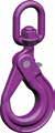


Standard type can not be swiveled when loaded. Not for welded system!
Foundry Hook GH/S
Chain Code
Weight Working Load Limit e h a b d1 d2 g s max. mm inch mm mm kg kg 6 1/4 HSB/S 6 110 20 17 71 21 11 28 1 0.52 1,400 7+8 9/32+5/16 HSB/S 7/8 136 26 20 88 25 12 34 1 0.92 2,500 10 3/8 HSB/S 10 169 30 29 107 35 17 45 1 1.57 4,000 13 1/2 HSB/S 13 205 40 35 138 40 20 52 1.50 3.19 6,700 16 5/8 HSB/S 16 251 50 41 168 50 27 60 2 6.24 10,000 19 3/4 HSB/S 19/20 290 62 50 194 60 30 70 2 9.75 16,000 22 7/8 HSB/S 22 322 65 52 211 70 32 81 2 11.45 19,000
–whenever 100 % is required, the best answer is to trust in a star.
31 Star Alloy G
100
Chain Code Dimensions
Weight Working Load Limit e h a d1 d2 g1 b mm inch mm kg kg
Dimensions
Chain Code Dimensions Weight Working Load Limit e h a w w1 d2 g s max. mm inch mm kg kg 6
WSB/S 6 161 20 17 35 36 12 28 1 1.20 1,400 7+8
182 26 20 35 36 12 34 1 1.54
10 3/8 WSB/S 10 218 30 29 42 40 16 45 1 2.14 4,000 13 1/2 WSB/S 13 269 40 35 49 47 20 52 1.5 4.42 6,700 16 5/8 WSB/S 16 319 50 41 60 60 24 60 2 7.34 10,000
1/4
9/32+5/16 WSB/S 7/8
2,500
Chain Code Dimensions Weight Working Load Limit e h a d1 d2 g b mm inch mm kg kg 7+8 9/32+5/16 GH/S 7/8 131 29 25 24 11 64 118 0.94 2,500 10 3/8 GH/S 10 158 35 32 31 14 76 143 1.62 4,000 13 1/2 GH/S 13 190 42 40 39 17 89 170 3.24 6,700 16 5/8 GH/S 16 224 50 46 47 22 102 200 5.65 10,000 19 3/4 GH/S 19/20 260 61 54 56 28 114 231 9.50 16,000

32 Lashing Chain Star Alloy SA/S – Measurements, Load Values, Weights Chain D Pitch P Li/min. Le/max. Weight LC Lashing Capacity Breaking Force mm inch mm mm mm kg/m kN kN 8 5/16 24 10,9 29 1.57 50 101 10 3/8 30 13,5 36 2.46 80 157 13 1/2 39 17,5 47 4.18 80 157 Chain acc. ASTM A973/A973M-01 Sheet Metal Plate Hook BH/S Chain Code Dimensions Weight Working Load Limit e s b h d1 g mm inch mm kg kg 7+8 9/32+5/16 BH/S 7/8 131 80 50 15 28 55 1.50 2,500 10 3/8 BH/S 10 170 100 70 20 36 65 2.80 4,000 13 1/2 BH/S 13 209 130 80 25 40 90 5.30 6,700 16 5/8 BH/S 16 263 160 100 30 50 110 10.50 10,000 19 3/4 BH/S 19/20 306 185 120 40 60 130 17.50 16,000 22 7/8 BH/S 22 368 220 140 50 75 150 30.50 19,000 Special types available upon request For lifting sheet metal stacks and boards. Recommended angle of inclination of the sling: 15-30°. Use min. 3-leg chain sling. Ratchet Load Binder RLS/S Code Max. Permissible Lashing Capacity LC Normal Tension Force STF Dimensions Weight Length L closed Length L open Tension range D d kN daN mm kg RLS/S 8 50 1,900 355 500 145 20 16 3.12 RLS/S 10 80 3,000 365 510 145 26 18 3.68 RLS/S 13 134 2,500 576 866 290 31 22 8.11 According to EN-specifications Special Accessories
Spare Parts
Forged Safety Latch Kits for Eye Sling Hooks and Clevis Sling Hooks
Chain Code
mm inch
Spare Part for
HKS/S 6 + HS/S 6 7+8 9/32+5/16 FG 7/8
6 1/4 FG 6
HKS/S 7 + HKS/S 8 + HS/S 7/8 10 3/8 FG 10
HKS/S 10 + HS/S 10 13 1/2 FG 13
HKS/S 13 + HS/S 13 16 5/8 FG 16
HKS/S 16 + HS/S 16 19 3/4 FG 19 HKS/S 19/20 + HS/S 19/20 22 7/8 FG 22
Pin Kits for Clevis Sling Hook and Shortening Hook
Chain Code
mm inch
Spare Part for
HKS/S 22 + HS/S 22 26 1 FG 26 HS/S 26 Pin
HKS/S 6 + VK/S 6 + PK/S 6 7 9/32 KBG/S 7 HKS/S 7 + VK/S 7 + PK/S 7 + GHK/S 7 8 5/16 KBG/S 8
6 1/4 KBG/S 6
HKS/S 8 + VK/S 8 + PK/S 8 + VHKS/S 8 + GHK/S 8 10 3/8 KBG/S 10
HKS/S 10 + VK/S 10 + PK/S 10 + VHKS/S 10 + GHK/S 10 13 1/2 KBG/S 13
HKS/S 13 + VK/S 13 + PK/S 13 + GHK/S 13 16 5/8 KBG/S 16 HKS/S 16 + VK/S 16 + PK/S 16 19 3/4 KBG/S 19 HKS/S 19/20 + PK/S 19/20 22 7/8 KBG/S 22 HKS/S 22 + PK/S 22
HKSB/S6
HKSB/S 13 16 5/8 KBG - HKSB/S 16 HKSB/S 16
G 100 –whenever 100 % is required, the best answer is to trust in a star.
33 Star
Alloy
Self
Kit for Clevis
Locking Hook Chain Code Spare Part for mm inch 6 1/4 KBG - HKSB/S 6
7 9/32 KBG - HKSB/S 7
HKSB/S7 8 5/16 KBG - HKSB/S 8 HKSB/S8 10 3/8 KBG - HKSB/S 10 HKSB/S 10 13 1/2 KBG - HKSB/S 13
V/S 6 7 9/32 BG-V/S 7
V/S 7 8 5/16 BG-V/S 8
V/S 8 + RSK/S 8 10 3/8 BG-V/S 10
V/S 10 + RSK/S 10 13 1/2 BG-V/S 13
V/S 13 + RSK/S 13 16 5/8 BG-V/S 16
V/S 16 + RSK/S 16 19 3/4 BG-V/S 19 V/S 19 22 7/8 BG-V/S 22
V/S 22 + RSK/S 22 26 1 BG-V/S 26 V/S 26
HSB/S 6 + HKSB/S 6 + WSB/S 6 7+8 9/32+5/16 HBG/S 7/8-8
HSB/S 7/8 + HKSB/S 7 + HKSB/S 8 + WSB/S 7/8 10 3/8 HBG/S 10-8
HSB/S 10 + HKSB/S 10 + WSB/S 10 13 1/2 HBG/S 13-8
HSB/S 13 + HKSB/S 13 + WSB/S 13 16 5/8 HBG/S 16-8
HSB/S 16 + HKSB/S 16 + WSB/S 16 19+22 3/4, 7/8 HBG/S 19+22 HSB/S 19+22
34
Safety Catch Kit for Eye Grab Hook with Safety Pin PS/S Chain Code
Spare Part for mm inch 7+8 9/32+5/16 PGS/S 7/8
Chain
PS/S 7/8 10 3/8 PGS/S 10 PS/S 10 13 1/2 PGS/S 13 PS/S 13 Pin Kit for Connecting Link and Webbing Coupling Link
Code
Spare Part for mm inch 6 1/4 BG-V/S 6
Trigger Kit for Self Locking Hooks Chain Code
Spare Part for mm inch 6 1/4 HBG/S 06-8
Working Load Tag with Wire Rope Binder and Fastener Code Code ID-Set 1/2/3/4-legs
Star Alloy G 100 –whenever 100 % is required, the best answer is to trust in a star.

Content Super Alloy Grade 80 37
of Super Alloy G 80 38 Sling Examples 39 Synoptical Table of Available Products 40-41
Alloy Chain 42
Alloy G 80 Working Load Limits 42 Master Links, Sub-Assemblies & Accessories 43-47 Special Accessories 48 Spare Parts 49-51
Characteristics
Super
Super
Super Alloy G 80 – Characteristics

Chain Quality: Super Alloy Chain SA Corresponds with EN 818-2 & machinery directive 2006/42/EC Stress at Load Capacity Limit: 200 N/mm2

Test Stress: 500 N/mm2 – corresponds to 2.5 times the load capacity Breaking Stress: 800 N/mm2 – corresponds to 4 times the load capacity Breaking Elongation: min. 20 % Bending acc. to EN 818-2: 0.8 x nominal diameter Permissible Working Temperature: Super Alloy Chain SA max. 400 °C Components max. 400 °C Grade marking: Super Alloy Chain SA 8 Components 8 Surface: Super Alloy Chain SA Black painted Components Powder coated Working Load Tag: Super Alloy Chain SA

38
All the required data is shown on the working load tag. Note: Working load tags should only be assembled acc. EN 818-4 and by competent persons. Working load tags should be used, solely when the respective chain & KWB components are assembled in the chain sling. Should alternative Working load limits arise in the chain sling through the use of special parts, the tags are impermissible. Disregard of these instructions can lead to material damage and personal injury. KWB will not assume liability.
Certificate
Clear Identification
Temperature -40° to 200 °C above 200° to 300 °C above 300° to 400 °C Load Factor Super Alloy 1 0.9 0.75 Asymmetric Load Distribution In this case the working load limit must be reduced by at least one chain leg, for example a 3-leg or 4-leg sling is to be classified as a 2-leg chain sling. In case of doubt, it must be supposed that only one of the chain legs carries the entire load. Edge Loads R = larger than 2x chain Ø R = larger than chain Ø R = chain Ø or smaller Load Factor 1 0.7 0.5 Impact Load slight impact medium impact strong impact Load Factor 1 0.7 impermissible
A test certificate is issued for all our products which certifies all the specified charcteristics.
Sample of tag for ready made chain sling
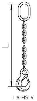
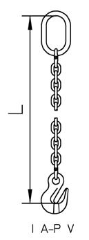
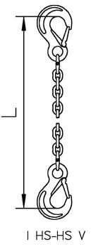
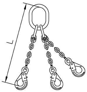
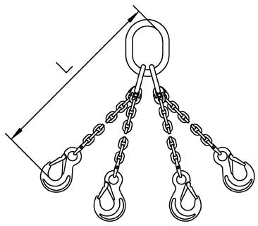
39 Super Alloy G 80 –Quality tested for your safety. Sling Examples III G-HSB V IV G-HS V I A-HS V I HS-HS V I A-HSB V I A-P V II A-HS V II A-HSB V II A-HS-P V II A-S V Example of Order Text: Super Alloy chain SA 10 mm, 2 legs with masterlink A and eye sling hook with forged safety latch HS, length 3,000 mm assembled with connecting link V. SA 10 II A - HS 3000 V Chain Nominal diameter Number of legs Master Link Hook Length Connecting link


40 Master Links & Sub-Assemblies 1-leg 2-leg 3 & 4-leg Super Alloy Chain Ø SA Master Link A Special Master Link T Master Link A Special Master Link T Sub-Assembly G Special Sub-Assembly TG mm inch Code Code Code Code Code Code 6 1/4 A 13 T 13 A 13 T 13 G 06/7.8 7 9/32 A 13 T 13 A 16 T 13 G 06/7.8 TG 07.8 8 5/16 A 16 T 13 A 18 T 16 G 08.8 TG 08.8 10 3/8 A 18 T 16 A 22 T 20 G 10.8 TG 10.8 13 1/2 A 22 T 20 A 26 T 26 G 13.8 TG 13.8 16 5/8 A 26 T 26 A 32 T 32 G 16.8 TG 16.8 18 11/16 A 32 T 32 A 36 T 38 G 18.8 20 3/4 A 36 T 32 A 36 T 38 G 20.8 22 7/8 A 36 T 38 A/T 45 A/T 45 G 22.8 26 1 A/T 45 A/T 45 A/T 50 A/T 50 G 26.8 32 1 1/4 A/T 50 A/T 50 A/T 56 A/T 56 G 32.8 36 A/T 56 A/T 56 A/T 56 A/T 56 40 A/T 56 Page 42 Page 43 Page 43 Page 43 Page 43 Page 43 Page 44 Connecting & Shortening Elements Super Alloy Chain Ø SA Connecting Link V Omega Shackle VU Webbing Coupling Link RSK Eye Grab Hook P Clevis Grab Hook PK Clevis Shortening Clutch (with Securing Part) VKL mm inch Code Code Code Code Code Code 6 1/4 V 06.8 U VU 06.8 P-06.8 VKL 06.8 7 9/32 V 07.8 U VU 07.8 P 07/8.8 PK 07/8.8 VKL 07.8 8 5/16 V 08.8 U VU 08.8 RSK 08.8 U P 07/8.8 PK 07/8.8 VKL 08.8 10 3/8 V 10.8 N VU 10.8 RSK 10.8/N P 10.8 PK 10.8 VKL 10.8 13 1/2 V 13.8 U VU 13.8 RSK 13.8 U P 13.8 PK 13.8 VKL 13.8 16 5/8 V 16.8 U VU 16.8 RSK 16.8 U P 16.8 PK 16.8 18 11/16 20 3/4 V 20.8 U VU 20.8 P 20.8 PK 20.8 22 7/8 V 22.8 P 22.8 26 1 V 26.8 VU 26.8 P 26.8 32 1 1/4 V 32.8 U P 32.8 Page 42 Page 44 Page 44 Page 44 Page 45 Page 45 Page 45


41 Super Alloy G 80 –Quality tested for your safety. Sling Hooks Super Alloy Chain Ø SA Eye Sling Hook with Forged Safety Latch HS Clevis Sling Hook with Forged Safety Latch HKS Eye Self Locking Hook HSB Clevis Self Locking Hook HKSB Swivel Safety Locking Hook WSB Foundry Hook GH mm inch Code Code Code Code Code Code 6 1/4 HS 06.8 U HKS 06.8 U HSB 06.8 HKSB 06.8 U WSB 06.8 7 9/32 HS 07/8.8 U HKS 07/8.8 U HSB 07/8.8 HKSB 07/8.8 U WSB 07/8.8 GH 07/8.8 8 5/16 HS 07/8.8 U HKS 07/8.8 U HSB 07/8.8 HKSB 07/8.8 U WSB 07/8.8 GH 07/8.8 10 3/8 HS 10.8 U HKS 10.8 U HSB 10.8 HKSB 10.8 U WSB 10.8 GH 10.8 13 1/2 HS 13.8 U HKS 13.8 U HSB 13.8 HKSB 13.8 U
13.8
16 5/8 HS 16.8 U HKS 16.8 U
16.8 HKSB 16.8 U
16.8
18 11/16 HS 20.8 U HSB
GH
20 3/4 HS 20.8 U HKS 20.8 U
GH
22 7/8 HS 22.8 U HKS 22.8 U HSB 22.8 26 1 HS 26.8 U 32 1 1/4 HS 32.8 U Page 42 Page 46 Page 46 Page 46 Page 47 Page 47 Page 47 Special Accessories Weld-on Hook HAS Ratchet Load Binder with Grab Hooks RLSP Ratchet Load Binder RLS Code Code Code HAS 1.3 RLSP 08 RLS 08 HAS 3.8 RLSP 10 RLS 10 HAS 6.3 RLSP 13 RLS 13 HAS 10 Page 48 Page 48 Page 48
WSB
GH 13.8
HSB
WSB
GH 16.8
20.8
20.8
HSB 20.8
20.8
42 Super Alloy Chain SA acc, EN 818-2 – Measurements, Load Values, Weights Chain D P Li / min. Le / max. Weight Working Load Limit Breaking Load mm inch mm mm mm kg/m kg kN 6 1/4 18 7.8 22.2 0.8
7 9/32 21 9.1 25.9 1.1
8 5/16 24 10.4 29.6 1.4
10 3/8 30 13 37
13
39 16.9
16 5/8 48
18 11/16 54 23.4
20 3/4 60
74
22 7/8 66
26 1 78 33.8
32 1 1/4 96 41.6 118 23 31,500
Safety factor 4:1 Maximum Working Load Limit for Super Alloy Chains Chain Ø 1-leg Chains 2-leg Chains 3- & 4-leg Chains Angle of Inclination 0<ß<45° 0<ß<60° 0<ß<45° 0<ß<60° Load Factor 1 1.4 1 2.1 1.5 Ø Load Capacity [kg] 6 1,120 1,600 1,120 2,360 1,700 7 1,500 2,120 1,500 3,150 2,240 8 2,000 2,800 2,000 4,250 3,000 10 3,150 4,250 3,150 6,700 4,750 13 5,300 7,500 5,300 11,200 8,000 16 8,000 11,200 8,000 17,000 11,800 18 10,000 14,000 10,000 21,200 15,000 20 12,500 17,000 12,500 26,500 19,000 22 15,000 21,200 15,000 31,500 22,400 26 21,200 30,000 21,200 45,000 31,500 32 31,500 45,000 31,500 67,000 47,500 If the chains are used in more demanding conditions (e.g. high temperature, asymmetric load distribution edge loads, impacts) the maximum load capacities in the table must be reduced, Please use the load factors on page 38 and refer to the specification in the user information, Super Alloy Chain
1,120 45.2
1,500 61.6
2,000 80.4
2.2 3,150 126
1/2
48.1 3.8 5,300 212
20.8 59.2 5.7 8,000 322
66.6 7.3 10,000 407
26
9 12,500 503
28.6 81.4 10.9 15,000 608
96.2 15.2 21,200 849
1,290
43 Super Alloy G 80 –Quality tested for your safety. Master Links, Sub-Assemblies & Accessories
Link A Chain Ø Code Commercial Code Measurements Weight
d t w s mm mm mm kg kg 6+7
A
A
*) Please refer to table „Maximum Working Load Limit“ on page 42 when using in chain slings. Special Master Link T Chain Ø Code Commercial Code Measurements Weight
*) d t w s mm mm mm kg kg 6+7+8 6+7 T 87.8 T 13 14 120 70 10 0.44 2,300 10 8 T 108.8 T 16 16.5 140 80 14 0.67 3,200 13 10 T 1310.8 T 20 20 160 95 14 1.21 5,400 16 13 T 1613.8 T 26 27 190 110 20 2.65 10,100 18+20 16 T 2016.8 T 32 33 230 130 26 4.78 15,700 22 18+20 T 2220.8 T 38 38 275 150 29 7.48 20,500 *) Please refer to table „Maximum Working Load Limit“ on page 42 when using in chain slings. Sub-Assembly G Chain Ø Code Commercial Code Measurements Weight Working Load Limit 0°-45° *) d t w d1 t1 w1 s e mm mm kg kg 6+7 G 06/7.8 G 06/7.8 19 135 75 13 60 38 10 195 1.23 4,200 8 G 08.8 G 08.8 23 160 90 16.5 70 34 14 230 2.27 7,600 10 G 10.8 G 10.8 27 180 100 19.5 85 40 14 265 3.43 9,600 13 G 13.8 G 13.8 33 200 110 23 115 50 17 315 6.60 13,780 16 G 16.8 G 16.8 36 260 140 27 140 65 20 400 10.06 20,800 18 G 18.8 G 18.8 45 340 180 33 150 70 490 19.14 30,700 20 G 20.8 G 20.8 50 350 190 33 150 70 500 22.87 34,100 22 G 22.8 G 22.8 50 350 190 36 170 75 520 24.79 40,000 26 G 26.8 G 26.8 56 400 200 40 170 80 570 37.75 54,000 32 G 32.8 G 32.8 70 460 250 50 200 100 660 66.60 76,000 *) Please refer to table „Maximum Working Load Limit“ on page 42 when using in chain slings.
Master
Working Load Limit 0°-45° *)
6 A 06/76.8
13 13 110 60 10 0.35 2,300 8 7 A 87.8
16 16.5 110 60 14 0.58 3,500 10 8 A 108.8 A 18 19 135 75 14 0.92 5,000 13 10 A 1310.8 A 22 23 160 90 17 1.60 7,600 16 13 A 1613.8 A 26 27 180 100 20 2.46 9,600 18 16 A 1816.8 A 32 33 200 110 26 4.10 13,600 20 18 A 2018.8 A 36 36 260 140 6.20 25,100 22 20 A 2220.8 A 36 36 260 140 6.20 25,100 26 22 A 2622.8 A 45 45 340 180 12.82 30,800 32 26 A 3226.8 A 50 50 350 190 16.55 40,000 36 32 A 3632.8 A 56 56 400 200 23.30 60,000 40 36 A 4036.8 A 56 56 400 200 23.30 60,000
Working Load Limit 0°-45°

44 Webbing Coupling Link RSK Chain Code Measurements Weight Working Load Limit b e s a g d c mm inch mm kg kg 8 5/16 RSK 08.8 U 68 66 18 29 19 10 12 0.36 2,000 10 3/8 RSK 10/N 82 81 21 40 24 13 15 0.616 3,150 13 1/2 RSK 13.8 U 100 104 28 50 28 16.5 19.5 0.57 5,300 16 5/8 RSK 16.8 U 110 112.5 40 47 33 21 21 1,52 8,000 Special Sub-Assembly TG Chain Ø Code Commercial Code Measurements Weight Working Load Limit 0°-45° *) e t w mm mm kg kg 7 TG 07.8 TG 07.8 280 160 95 2.14 3,150 8 TG 08.8 TG 08.8 310 170 105 3.10 4,250 10 TG 10.8 TG 10.8 350 190 110 5.21 7,000 13 TG 13.8 TG 13.8 420 230 130 9.44 13,200 16 TG 16.8 TG 16.8 505 275 150 17.04 20,500 *) Please refer to table „Maximum Working Load Limit“ on page 42 when using in chain slings. Connecting Link V Chain Code Measurements Weight Working Load Limit g s b e c d mm inch mm kg kg 6 1/4 V 06.8 U 14.1 11 39 44.4 7.8 7.6 0.10 1,120 7 9/32 V 07.8 U 17 13 47 51 10 9 0.18 1,500 8 5/16 V 08.8 U 18.35 14 55 62 11.5 10 0.22 2,000 10 3/8 V 10.8 N 24 18 64 72 15 13 0.33 3,150 13 1/2 V 13.8 U 27.6 22 79 88 19 16.7 0.88 5,300 16 5/8 V 16.8 U 33 29 106 103 21 21 1.65 8,000 20 3/4 V 20.8 U 41.7 35 123 115 29.5 23.5 2.76 12,500 22 7/8 V 22.8 48 39 150 133 27 27 3.24 15,000 26 1 V 26.8 U 61 46 159 164 32 30 4.76 21,200 32 1 1/4 V 32.8 U 80 50 195 194 40 32 9.55 31,500 Omega Shackle VU Chain Code Measurements Weight Working Load Limit e b d s a M mm inch mm kg kg 6 1/4 VU 06.8 34 21 9 11 16 7 0.077 1,120 7 9/32 VU 07.8 49 28 13 16 22 8 0.22 1,500 8 5/16 VU 08.8 48 28 13 16 22 10 0.22 2,000 10 3/8 VU 10.8 60 35 16 20 27 12 0.41 3,150 13 1/2 VU 13.8 72 39 18 24 34 16 0.65 5,300 16 5/8 VU 16.8 80 47 23 32 44 20 1.34 8,000 20 3/4 VU 20.8 96 56 26 36 52 24 2.03 12,500 26 1 VU 26.8 132 77 33 49 66 30 4.70 21,200 A-link A-link


45 Super Alloy G 80 –Quality tested for your safety. Eye Grab Hook P Chain Code Measurements Weight Working Load Limit g d2 d1 e a b mm inch mm kg kg 6 1/4 P 06.8 * 7 9 12 50 26 41 0.14 1,120 7+8 9/32+5/16 P 07/8.8 * 9 12 16 65 34 55 0.35
10 3/8 P
* 12 14 20 77 46
13 1/2 P
* 15 19
16 5/8 P
* 19
18+20 11/16+3/4 P
25 27
151
22 7/8 P
27 31 42 170
26 1 P
32 37 50
32 1 1/4 P
39 44 60 245
Clevis Shortening Clutch VKL Chain Code Measurements Weight Working Load Limit e b d mm inch mm kg kg 6 1/4 VKL 06.8 45 36 7.4 0.27 1,120 7 9/32 VKL 07.8 58 44 9 0.5 1,500 8 5/16 VKL 08.8 58 44 10 0.5 2,000 10 3/8 VKL 10.8 70 55 12.5 0.8 3,150 13 1/2 VKL 13.8 1) 90 70 16 1.53 5,300 1) clevis connector with bent hitch pin, see figure • only load the inside chain • only to be used with safety device • make sure that the chain fits properly Warning Instructions: Clevis Grab Hook PK Chain Code Measurements Weight Working Load Limit g d e a b mm inch mm kg kg 7+8 9/32+5/16 PK 07/8.8 * 9 9 63 34 55 0.40 2,000 10 3/8 PK 10.8 * 12 12.5 78 46 69 0.79 3,150 13 1/2 PK 13.8 * 15 16 93 60 89 1.61 5,300 16 5/8 PK 16.8 * 19 20 115 70 110 3.00 8,000 20 3/4 PK 20.8 25 24 141 84 150 6.15 12,500
2,000
10.8
69 0.65 3,150
13.8
26 101 60 89 1.44 5,300
16.8
23 32 121 70 110 2.40 8,000
20.8
36
84 150 6.15 12,500
22.8
91 165 8.30 15,000
26.8
201 107 195 13.80 21,200
32.8
139 231 20.27 31,500
Eye Sling Hook with Forged Safety Latch HS
Clevis Sling Hook with


46
Chain Code Measurements Weight Working Load
g1 d2 d1 e a h b mm inch mm kg kg 6
U
7+8
HS
U
10
13
16
22
26
U
32
U
Limit
1/4 HS 06.8
19 10 20 85 17 21 68 0.34 1,120
9/32+5/16
07/8.8
26 11 25 106 19 27 88 0.60 2,000
3/8 HS 10.8 U 31 16 34 131 26 33 109 1.25 3,150
1/2 HS 13.8 U 39 19 43 164 33 44 134 2.36 5,300
5/8 HS 16.8 U 45 25 50 183 40 50 155 3.77 8,000 18+20 11/16+3/4 HS 20.8 U 53 27 55 205 48 55 178 6.01 12,500
7/8 HS 22.8 U 62 29 60 225 50 62 196 8.19 15,000
1 HS 26.8
62 37 70 260 70 62 235 12.76 21,200
1 1/4 HS 32.8
87 37 70 299 87 97 291 22.31 31,500
Chain Code Measurements Weight Working Load Limit g1 a h d e b mm inch mm kg kg 6 1/4 HKS 06.8 U 19 15 20 7.4 69 66 0.29
7+8 9/32+5/16 HKS 07/8.8 U 26 19 28 9 95 90 0.63 2,000 10 3/8 HKS 10.8 U 31 25 35 12.5 109 108 1.14 3,150 13 1/2 HKS 13.8 U 39 34 41 16 136 131 2.25 5,300 16 5/8 HKS 16.8 U 45 37 49 20 155 153 3.69 8,000 20 3/4 HKS 20.8 U 53 51 53 24 184 177 5.60 12,500 22 7/8 HKS 22.8 U 62 52 62 27 214 196 9.13 15,000 Eye Self Locking Hook HSB Chain Code Measurements Weight Working Load Limit g d2 d1 e b a h s max. mm inch mm kg kg 6 1/4 HSB 06.8 28 11 21 110 71 17 20 1 0.52 1,120 7+8 9/32+5/16 HSB 07/8.8 34 12 25 136 88 20 26 1 0.92 2,000 10 3/8 HSB 10.8 45 17 32 169 107 29 30 1 1.57 3,150 13 1/2 HSB 13.8 52 20 40 205 138 35 40 1.5 3.19 5,300 16 5/8 HSB 16.8 60 27 50 251 168 41 50 2 6.24 8,000 18+20 11/16+3/4 HSB 20.8 70 30 60 290 194 50 62 2 9.75 12,500 22 7/8 HSB 22.8 81 32 70 322 211 52 62 2 11.45 15,000 Not for welded system!
Forged Safety Latch HKS
1,120


47 Super Alloy G 80 –Quality tested for your safety. Swivel Self Locking Hook WSB Chain Code Measurements S max. Weight Working Load Limit e h d2 w a g mm inch mm mm kg kg 6 1/4 WSB 06.8 161 20 12 35 16 28 1 1.20 1,120 7+8 9/32+ 5/16 WSB 07/8.8 182 26 12 35 20 34 1 1.54
10 3/8 WSB 10.8 218 30 16 42 25 45 1
13 1/2 WSB 13.8 269 40 20 49 35 52 1.5
16
WSB
319 50 24 60 35 60 2
Clevis Self Locking Hook HKSB Chain Code Measurements S max. Weight Working Load Limit g d e a b h mm inch mm mm kg kg 6 1/4 HKSB 06.8 U 28 7.4 94 17 71 20 1 0.56 1,120 7+8 9/32+ 5/16 HKSB 07/8.8 U 34 9 123 20 88 26 1 0.87 2,000 10 3/8 HKSB 10.8 U 45 12.5 144 29 107 30 1 1.61
13
HKSB 13.8 U 52 16 180 35 138 40 1.5
16 5/8 HKSB 16.8 U 60 20 218 41 168 50 2
Standard type can not be swivelled when loaded. Not for welded system! Foundry Hook GH Chain Code Measurements Weight Working Load Limit g d2 d1 e a h b mm inch mm kg kg 7+8 9/32+5/16 GH 07/8.8 64 11 24 131 25 29 118 0.94
10 3/8 GH 10.8 76 14 31 158 32 35 143
13 1/2 GH 13.8 89 17 39 190 40 42 170 2.89
16 5/8 GH 16.8 102 22 47 224 46 50 200 5.17
18+20 11/16+3/4 GH 20.8 114 28 56 260 54 61 231 9.20 12,500
2,000
2.14 3,150
4.42 5,300
5/8
16.8
7.34 8,000
3,150
1/2
3.24 5,300
5.96 8,000
2,000
1.69 3,150
5,300
8,000


48 Weld-on Hook HAS Code Measurements Weight Working Load Limit L H G B C mm kg kg HAS 1.3 95 74 20 25 34 0.68 1,300 HAS 3.8 132 106 26 35 40 1.42 3,800 HAS 6.3 167 133 29 45 49 2.96 6,300 HAS 10 175 136 29 50 49 4.03 10,000 Special Accessories (Note Working Load Limits!) Lashing Chain Super Alloy SA acc. EN 818-2 – Measurements, Load Values, Weights Chain D Pitch P Li/min. Le/max. Weight LC Lashing Capacity Breaking Force mm inch mm mm mm kg/m kN kN 8 5/16 24 10.4 29.6 1.4 40 80.4 10 3/8 30 13 37 2.2 63 126 13 1/2 39 16.9 48.1 3.8 100 212 Safety factor 2:1 Ratchet Load Binder RLS Code Max. Permissible Lashing Capacity LC Normal Tension Force STF Length Closed L Length Open L Tension Range D d Weight kN daN mm kg RLS 08 40 1,900 355 500 145 20 16 3.12 RLS 10 63 1,900 355 500 145 20 16 3.12 RLS 13 100 3,000 365 510 145 26 18 3.68 Only for lashing. Not for lifting purposes! Ratchet Load Binder with Grab Hooks RLSP Code Max. Permissible Lashing Capacity LC Normal Tension Force STF Length Closed L Length Open L Tension Range Width Opening g Weight kN daN mm kg RLSP 08 40 1,900 586 731 145 12 4.39 RLSP 10 63 1,900 626 771 145 15 5.22 RLSP 13 100 3,000 708 853 145 19.5 8.09 Only for lashing. Not for lifting purposes! Weldable Safety Hook e.g. excavator buckets. According to safety specifications. Please consider welding instructions!
49 Super Alloy G 80 –Quality tested for your safety. Safety Latch Kit for Weld-on Hooks HAS Chain Spare Part for SFG-A1 HAS
SFG-A3 HAS
SFG-A6 HAS
HAS 10
Parts Forged Safety Latch Kit for Clevis and Eye Sling Hooks Chain Code Forged Latch Spare Part for mm inch 6 1/4 FG 06
7+8 9/32+5/16 FG 07.8
10
FG 10
13
FG 13
16
FG 16
20
FG 20
22
FG 22
26 1 FG 26
32 1
FG 32
Trigger Kit for Self Locking Hooks Chain Code for HSB/WSB/HKSB...U Spare Part for mm inch 6 1/4 HBG 06.8 U HSB/HKSB/WSB 06.8 U 7+8 9/32+5/16 HBG 7/8.8 U HSB/HKSB/WSB 7/8.8 U 10 3/8 HBG 10.8 U HSB/HKSB/WSB 10.8 U 13 1/2 HBG 13.8 U HSB/HKSB/WSB 13.8 U 16 5/8 HBG 16.8 U HSB/HKSB/WSB 16.8 U 18+20+22 11/16+ 3/4+7/8 HBG 20/22.8 U HSB 20.8+HSB 22.8 U
1.3
3.8
6.3;
Spare
HKS/HS 06.8U
HKS/HS 07/8.8 U
3/8
HKS/HS 10.8 U
1/2
HKS/HS 13.8 U
5/8
HKS/HS 16.8 U
3/4
HKS/HS 20.8 U
7/8
HKS/HS 22.8 U
HS 26.8 U
1/4
HS 32.8 U
50 Load Pin Kit for Clevis Self Locking Hook Chain Code Spare Part for mm inch 6 1/4 KBG-HKSB 06.8 U HKSB 06.8 U 7+8 9/32+5/16 KBG-HKSB 07/8.8 U HKSB
U 10 3/8 KBG-HKSB
U HKSB
U 13 1/2
U
U 16 5/8
U 20
U 22 7/8 KBG-HKSB
U
U Load Pin Kit for Clevis Sling Hook and Shortening Clutch Chain Code Spare Part for mm inch 6 1/4 KBG 06 U HKS 06.8 U; VKL 06.8 7+8 9/32+5/16 KBG 07/8 U HKS 7/8.8; U VKL 07.8 8 5/16 KBG 08 U VKL 08.8 10 3/8 KBG 10 U HKS 10.8 U; VKL 10.8 13 1/2 KBG 13 U HKS 13.8; U VKL 13.8 16 5/8 KBG 16 U HKS 16.8 20 3/4 KBG 20 U HKS 20.8 22 7/8 KBG 22 U HKS 22.8 Load Pin Kit for Clevis Shortening Hook PK Chain Code Spare Part for Code Spare Part for mm inch 7+8 9/32 + 5/16 KBG 07/8 PK 07/8.8 KBG 07/8 U PK 07/8.8 NEW design 10 3/8 KBG 10 PK 10.8 KBG 10 U PK 10.8 NEW design 13 1/2 KBG 13 PK 13.8 KBG 13 U PK 13.8 NEW design 16 5/8 KBG 16 PK 16.8 KBG 16 U PK16.8 NEW design 20 3/4 KBG 20 PK 20.8 KBG 20 U Load Pin Kit for Connecting Link Chain Code Spare Part for Code Spare Part for mm inch 6 1/4 BG-V 06.8 U V 06.8 U BG-V 06.8 V 06.8 7 9/32 BG-V 07.8 U V 07.8 U BG-V 07.8 V 07.8 8 5/16 BG-V 08.8 U V 08.8 U/RSK 08.8 U BG-V 08.8 V 08.8 10 3/8 BG-V 10.8 U V 10.8 U/RSK 10.8 U BG-V 10.8 V 10.8/RSK 10 13 1/2 BG-V 13.8 U V 13.8 U/RSK 13.8 U BG-V 13.8 V 13.8/RSK 13 16 5/8 BG-V 16.8 U V 16.8 U/RSK 16.8 U BG-V 16.8 V 16.8 18+20 11/16+3/4 BG-V 20.8 U V 20.8 U BG-V 20.8 V 20.8 22 7/8 BG-V 22.8 U V 22.8 U BG-V 22.8 V 22.8 26 1 BG-V 26.8 U V 26.8 U BG-V 26.8 V 26.8 32 1 1/4 BG-V 32.8 U V 32.8 U BG-V 32.8 V 32.8
07/8.8
10.8
10.8
KBG-HKSB 13.8
HKSB 13.8
KBG-HKSB 16.8 U HKSB 16.8
3/4 KBG-HKSB 20.8 U HKSB 20.8
22.8
HKSB 22.8
UBMS 05.6
UBMS 07
VU 06.8
VU 07.8
UBMS 08 VU 08.8
UBMS 10 VU 10.8
UBMS 13 VU 13.8
UBMS 16 VU 16.8
UBMS 19 VU 20.8
UBMS 26 VU 26.8
51 Super Alloy G 80 –
Quality tested for your safety. Screw Set for Omega Shackle VU Code
Spare Part for mm
Working Load Tag with Wire Rope Binder and Fastener Code ID-Set 1/2/3/4-legs
General
KWB sling chains and accessories can be used for general lifting purposes acc. EN 818-4. Chains should only be used by trained personnel, who have read and understood the instructions for use. KWB sling chains and components should not be altered e.g. twisting, grinding, removing of parts and drilling. The surface of the chains and accessories should not be subjected to acids or caustic solutions. If necessary please contact the KWB technical department.
Only use the KWB chains and accessories up to the indicated temperature. Should the temperature be exceeded the reduction of the load capacity must be taken into consideration (see pages 8, 19, 38). In the event of temperatures outside this range, do not use the chain slings.
Do not use KWB lifting chains and accessories in acids, alkalines or chemicals or expose them to their fumes.
Important: Certain production procedures release acids and or fumes. If necessary please contact KWB. In especially dangerous conditions (e.g. offshore applications, lifting of persons or potentially dangerous loads i.e. molten metals, corrosive materials, nuclear substances) the working load limit must be adjusted according to the risk level by an expert.
Inspection & Maintenance
Before using any lifting equipment for the first time please check the following:
- The sling chain corresponds exactly to the order.
- The test certificate or certificate of conformity have been supplied.
- Marking & working load limit of the chain correspond with the information on the test certificate or certificate of conformity.
- All the data regarding the sling chain has been entered in a register for lifting equipment, if required.
- Before use check the chains for visible damage or signs of wear. In case of damage do not use the chains. In case of doubt likewise.
- Sling chains depending on use should be inspected by an expert once a year i.e. after unusual events that could cause impairment of the chain sling.
- Every two years it is recommended that the chain be subjected to a load test 1.5 times the working load limit, followed by a visual inspection.
When one or more of the following criteria is fulfilled, the chain must be taken out of use:
- Broken link.
- Missing working load tag on the chain sling or illegible marking on the tag.
- Elongation of the chain. The chain must be discarded if t >1.05 tn (see catalogue).
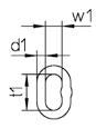
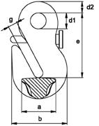
- Wear: Wear is determined as the mean value of two measurements of diameters d1 and d2 carried out a right angle (see drawing). The chain must be discarded.
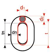
dm = d1 + d2 < 09 dn 2
- Cuts, notches, grooves, surface cracks, excessive corrosion, discoloration due to heat, signs of additional welding, twisted links or other faults.
- Missing i.e. non-functioning safety device or signs of widening of the hook i.e. noticeable enlargement of the opening or other forms of deformation.
Some of the imagery featured in the catalog are artistic depictions and do not show the actual application of the products.
52
G12, G10, G8
User Information
Designation
Dimensions
Max. Change Permitted
Chain D -10 % P +5 %
Rings d -10 % t +10 %
Hooks *) e +5 % h, d2 -10 % g, g1 +10 %
V, RSK
Both halves must be free to move No change permitted e +5 % c -10 %
Connecting link VU Bolts must be free to move No change permitted e +5 % d and M -10 %
Clevis Bolts and Bolts for Connecting Links + Webbing Coupling Links
d -10 %
HSB, HKSB, WSB Tip opening 2 x s max.
*) HKSB/SUN, HKS/SUN
VK/S, P/S, PS/S, PK/S, HKS/S, VHKS/S, HKSB/S, GHK/S, HS/S, HSB/S, WSB/S, GH/S, BH/S, HS, GH, P, HKS, PK, VHKS, VKL, WSB, HKSB, HSB
KWB chain slings should only be repaired by qualified personnel. Records of the inspections and repairs must be kept on file for the entire service life of the chain sling.
KWB chain slings should be stored in dry condition & protected from corrosion (preferably oiled).
Correct Use of Chain Slings
KWB chain slings should only be used with the angle of inclination indicated on the working load tag. Avoid angles of inclination under 15°. Never use the chain slings with an angle of inclination exceeding 60°. If KWB chains are guided over edges protective padding should be used to avoid damage or the load capacity reduced (see pages 8, 19, 38). But if chains looped at a beam or other round shaped loads the diamater should be minimum thrice the chain pitch. For smaller diameters the WLL of the chain must be reduced by 50 %.
In cases of possible impact load the working load limit of the KWB chains should be scaled down acc. to the table on pages 8, 19, 38. Impact/shock can be defined as follows:
- Slight impact: arises e.g. when the lifting or lowering movement is accelerated.
- Medium impact: occurs e.g. when the chain slips during adjustment to the shape of the load.
- Strong impact: arises e.g. when the load falls into the unloaded chain.
KWB lifting chains and components are rated according to regulations for 20,000 load cycles. At high dynamic forces there may nevertheless be a risk of damage to the chain and accessories. According to the employer´s liability insurance association Metall Nord Süd this risk may be prevented if the stress at load capacity limit is reduced by using a larger chain dimension.
The load capacities of KWB chain slings are defined with the assumption that the load of the individual chain legs is distributed symmetrically. The load can still be considered symmetrical when all the following conditions are complied with:
- The load is smaller than 80 % of the indicated working load limit.
- The angle of inclination of all chain legs is not less than 15°.
- The angle of inclination of all chain legs are equal or deviate max. 15° from each other.
- In the case of 3- and 4-leg chain slings, the corresponding angles in the sling level deviate max. 15° from each other.
Should these parameters not be met, then the load is considered asymmetric and an expert must be called to evaluate the lifting process. In case of doubt the load capacity must be reduced to that of a single-leg chain sling. Individual chain legs which are not in use must be hung back into the master link and the working load limit reduced accordingly.
53
54 Notes
55 Notes
KWB Ketten Austria GmbH
A-9020 Klagenfurt, Schleppe-Platz 8
Phone: +43 463 48 80-355 Fax: +43 463 48 80-350 kwb@kwb-ketten.at, www.kwb-ketten.at

KA/22/00542
