20 minute read
PROTOTYPE AND DESIGN OF SIX-AXIS ROBOTIC MANIPULATOR
Submitted: 21st July 2021; accepted 22nd February 2022
Mateusz Pająk, Marcin Racław, Robert Piotrowski
Advertisement
DOI: 10.14313/JAMRIS/1-2022/5
Abstract:
The paper presents a design for a six-axis manipulator. The design consists of specially designed solutions for housing, planetary gearboxes, and electronics. The manipulator is controlled by a supervisory control system. The use of a series of measuring elements allows tracking of the current position of each axis. This can be used to create a cascade control loop with velocity and acceleration feed-forward. The implemented control algorithm together with the microcontroller software allows one to tune parameters of the controllers for both control loops: inner, related to the speed of the robot; outer, related to its position.
Keywords: industrial manipulators, servostepper motors, cascade control, stateful machine
1. Introduction
The uninterrupted technological development in industrial branches that was initiated decades ago has replaced human participation in some hard and monotonous work with robot work. Initially, devices that were used made it only slightly easier to perform harder tasks. Most of them still required considerable human intervention. Their operation was limited to only simple movements such as lifting or moving elements.
Replacement of human participation in work that requires much effort and precision has opened opportunities for dynamic development of computer-controlled machines. More and more modern machines appeared, bringing with them the possibility of performing more and more complex tasks. This made it possible to partially eliminate the role of the human being as an unit of the lowest degree of production. The rapid increase in use of programmable machines allowed advanced units to enter production lines. The first industrial use of a robotic manipulator is credited to the automotive industry, in the case of General Motors. The robots were used to handle heavy metal parts. However, the real breakthrough in the design of manipulators was made in 1969: the Stanford arm manipulator with two rotary connections, prismatic and spherical. This design significantly increased handling capabilities of robots [1].
As a result of mass technological development, industrial robots, and with them various types of manipulators, have found their place in many industrial branches. Currently, they can be found in the automotive industries as well as in food production. Due to their multi-tasking capabilities, they can be used in tasks that require use of high forces, for instance, transferring heavy materials, or exceptional precision, as in the case of precision soldering. Replacement of the actuator allows the manipulator to be adapted to the prevailing conditions or purpose, enabling it to perform a range of tasks such as welding, material processing, or assembling available parts together. However, despite their versatile uses, their biggest advantage is the ability to cooperate with people on production lines, enabling maximization of profits while reducing human effort.
The goal of this article is the physical representation of a miniature version of an industrial manipulator with an executive element. During the design process, it was decided to use a mechatronic approach using knowledge of mechanics, electronics, control engineering, and computer science. The work can be divided into two main stages: modeling and physical representation. The modeling process included the implementation of a three-dimensional model of the robot housing, a model of the control algorithm, and modeled electronic connections. The construction stage consists of the implementation of the housing, connection of actuators, implementation of control algorithms, and integration all of the above individual components. Due to the robot’s structure, it is considered as a dynamic, non-linear, and unstable system.
2. Design of the Physical Part of the Project
2.1. Size of the Manipulator and Selection of Motors
The design assumptions determined the dimensions of the robot, its load capacity, and its shape. The first and most important step in the construction process was to determine preliminary dimensions of particular components. Knowledge of such dimensions allowed for selection of the motors. During motor selections many parameters were taken into account, such as their type (stepper motor), winding, current value, load curve, and price. Finally, appropriate motors were selected using basic mechanical relationships related to the mass of elements and their arrangement. Their selection directly determined the final dimensions of the manipulator. The final version in the base position reached a height not exceeding 40 cm.
Arranging the arm in a horizontal position, the most critical in terms of load, allowed the manipulator to reach objects more than half a meter away, measured from the first axis of rotation.
2.2. Three-dimensional Model of the Manipulator
generally found in the automotive industry. The initial stage of the project was to use so-called reverse engineering on motors, consisting in obtaining a three-dimensional model from existing elements. Their virtual version allowed the starting of the design stage of subsequent parts of the manipulator. The fundamental part of the model is the base with the axis 1 motor placed in it. It forms the basis of the whole robot. Its design divides it into two parts that can be easily connected. Appropriate holes have also been made to allow the device to be permanently attached at the workplace. The base model includes mounting holes for the base motor inside of it , which allows for connection of the motor shaft with gearing. It was decided to make custom planetary gearboxes due to the nonstandard dimensions of the collective elements. To obtain proper movement of joints, a special system that holds gearboxes with joints together was designed to integrate both the gearbox and a custom-designed ball bearing system into the chassis. Also, appropriate recesses were made to allow easy and effective placement of bearing balls around the ring gears of the gearbox. The combination of these two elements made i t possible to obtain a suitable gearbox ratio at the output , and to ensure its smooth course.
The purpose of the designed model was to make its functionality and appearance similar to robots generally found in the automotive industry. The initial stage of the project was to use so-called reverse engineering on motors, consisting in obtaining a three-dimensional model from existing elements. Their virtual version allowed the starting of the design stage of subsequent parts of the manipulator. The fundamental part of the model is the base with the axis 1 motor placed in it. It forms the basis of the whole robot. Its design divides it into two parts that can be easily connected. Appropriate holes have also been made to allow the device to be permanently attached at the workplace. The base model includes mounting holes for the base motor inside of it, which allows for connection of the motor shaft with gearing. It was decided to make custom planetary gearboxes due to the nonstandard dimensions of the collective elements. To obtain proper movement of joints, a special system that holds gearboxes with joints together was designed to integrate both the gearbox and a custom-designed ball bearing system into the chassis. Also, appropriate recesses were made to allow easy and effective placement of bearing balls around the ring gears of the gearbox. The combination of these two elements made it possible to obtain a suitable gearbox ratio at the output, and to ensure its smooth course.
ones. Bigger modules allowed more infill material inside the teeth which made for a stronger support structure. The smaller pieces would be more prone to deformation as the outer shell of 3D printed parts is processed more for quality rather than durability by most of the available 3D printing software. To achieve this task the correct selection of the number of teeth was required. For this purpose, the equation (1) describing the relationship between the number of teeth on planets (P1-P2), rings (R1-R2), and the sun (S1) in relation to the ratio (R) was applied. Due to the forces needed to move individual axles, it was decided to set the ratio at the level of 30–45: 1. This value of the gear ratio allowed for smooth movement with sufficient power needed to move. The limitations in the method of execution resulted in top-down ranges as to the number and size of teeth in gears. Using the intended number of teeth on one of the gears, the values of the others were found using the equation.
stronger support structure. The smaller be more prone to deformation as the printed parts is processed more for than durability by most of the available software. To achieve this task the correct the number of teeth was required. For the equation (1) describing the relationship the number of teeth on planets (P1-P2), and the sun (S1) in relation to the applied. Due to the forces needed to axles, it was decided to set the ratio at 45: 1. This value of the gear ratio allowed movement with sufficient power needed limitations in the method of execution down ranges as to the number and gears. Using the intended number of the gears, the values of the others were the equation.
(1)
(1)
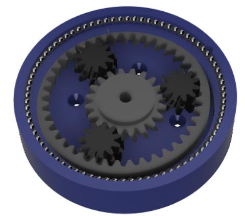
The result was two transmission sizes with a ratio of 41:1 for the first axis motor and 32:1 for the 4–6 axis motors. Connecting the axle with custom planetary gears requires two levels defining the desired gear ratio. In the lower part, most of the elements are mounted together with planets with double number of teeth (Fig. 1). The upper part contained a ring necessary for the axis movement.
From the mechanical point of view, the biggest load is placed on the second axis. Because the dimensions of the motor of the second axis were increased, it was decided to make a custom mount for it, allowing it to be placed in the axis of rotation of the previous axis. Due to the high forces acting on this axle, a special, dedicated metal gearbox was purchased. To make sure that the plastic case of second axle will not break due to the big load that it is supposed to carry , it has been reinforced with three metal rods that were connected to the shaft of the motor. Their installation inside the housing significantly strengthened the entire structure, increasing the resistance to material destruction caused by the shear moment generated by the motor.
From the mechanical point of view, the biggest load is placed on the second axis. Because the dimensions of the motor of the second axis were increased, it was decided to make a custom mount for it, allowing it to be placed in the axis of rotation of the previous axis. Due to the high forces acting on this axle, a special, dedicated metal gearbox was purchased. To make sure that the plastic case of second axle will not break due to the big load that it is supposed to carry, it has been reinforced with three metal rods that were connected to the shaft of the motor. Their installation inside the housing significantly strengthened the entire structure, increasing the resistance to material destruction caused by the shear moment generated by the motor.
2.3. Custom Planetary Gears
While selecting actuators, it was decided to use two stepper motors with pre-attached planetary metal gearboxes for axes two and three as plastic ones potentially could not handle required torques. Their ratio allows them to obtain the necessary moment for the appropriate axle. In order to reduce cost, other motors were connected to individual 3D printed gearboxes. The model of the manipulator was designed in the Autodesk Inventor 2019 environment [2] with functionality in mind. By using gears with larger teeth and modules, it was possible to achieve a better gear ratio with less mechanical wear than by using smaller
The result was two transmission sizes 41:1 for the first axis motor and 32:1 motors. Connecting the axle with custom gears requires two levels defining the ratio. In the lower part, most of the mounted together with planets with of teeth (Fig. 1). The upper part contained necessary for the axis movement.
2.4. The gripper
In the project it was planned to obtain an independent executive element in the form of a gripper. The design of its individual components as a separate object aims to achieve relative modularity. The special design allows easy connection with the arm and gives the opportunity to replace it with another actuator if needed. The gripper has a single servo motor as its actuator. In the design process of the tool, accuracy and high precision were the most important aspects. The main components are the appropriate gears re- sponsible for the transfer of force from the servo and gripping parts. Their specific shape allows for gripping both regular oval objects and irregular objects.
3. Realization of Manipulator and Gripper
3.1. Case of the Manipulator and Gripper
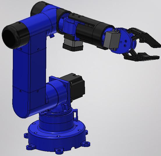
The elements of the manipulator were created by using 3D printing technology. The ability to print almost any shape allowed for effective production of individual housing parts. Proper stiffness and durability of elements was achieved by appropriate thickness of components and the use of appropriate material. Two types of material were used in the printing process: PLA (polylactic acid, polylactide) and PETG (polyethylene terephthalate). The first of them is used to make the entire housing and the gripper, as it is easier to print and postprocess. Due to the highest mechanical load, it was decided to use a filament with much higher strength (PETG) for the production of gears. Because of limited possibilities associated with the available print field, individual parts had to meet the requirements related to their size. As a result, a modular representation of the entire manipulator was obtained (Fig. 2). To facilitate the process of joining elements, the robot was assembled using bolts and nuts of various sizes.
municate with the master system. The heart of the system is the 32 bit STM32F103RBT6 microcontroller. The main selection criterion was the number of counters and the appropriate number of I/O. On the board, apart from the microcontroller, there are two voltage controllers: 3.3V and 5V. With those controllers, it is possible to power the logic with motor power supply (24V). The 3.3V voltage is used to power the microcontroller, A4988 controllers located on another module, encoders, and as a reference voltage for the limit switches located on the manipulator. 5V supplies the TB6600 controllers, which are controlled from the microcontroller through the 74HC245 IC which acts as a logic level converter. The role of the master device was played by a PC computer communicating with the motherboard through a USB / Serial converter.
The next module is the AM4096 magnetic encoder board. The selection criterion was very high resolution: 4096 pulses per revolution and numerous communication options. In addition to the encoder IC, the board only has filter capacitors and a four-pin connector. Ready encoder modules were mounted on the rear parts of the stepper motors. For communication with the motherboard, it was decided to use the I2C bus. Before using the encoders, they had to be configured; also, different I2C addresses had to be set. Configuration was done using an Arduino UNO board.
Control of stepper motors is done by using additional systems that act as controllers. In order to control the motors of the second and third axes, it was decided to use TB6600 controllers, which are able to supply current up to 4A per coil. Control of the remaining motors was achieved by means of popular A4988 controllers. Due to their physical structure, which prevents direct mounting on the base, adapters were made. Each of them has two controllers. The adapters have screw connectors connecting the motors with controllers and their power supply.
The motherboard was made by an external company. The remaining modules were made using the thermal transfer method [3].
3.2. Project and Realization of the Electronic Boards
Due to the large amount of electronics required to control the robot, it was decided to divide the electronic part into a set of dependent modules arranged in the robot base. The electronic part project was started by dividing the required electronics into modules and by planning the topology of connections between them. Finally, the electronics were divided into 6 modules, whose logic inputs / outputs were connected by ribbon cables using ribbon connectors.
The most important and the most complicated module is the motherboard. Its task is to coordinate the work of other modules, read the sensors, send control signals, perform control algorithms, and com-
A separate Atmega328p microcontroller in the form of an Arduino Nano was used to control the gripper, which communicates with the motherboard via second I2C bus. The use of an additional microcontroller gives the opportunity to change the type of tool, thereby increasing the number of potential applications of the robot and creating a multi-task device. The gripper is driven by the MG995 servo motor.
4. Control system
The manipulator control was made using a hierarchical layered structure (Fig. 3) [4]. The top layer is the PC, and the bottom was the control system. The master control system sets the current position of the manipulator, its movement, and control parameters. The manipulator’s control board only listens to the commands as a slave device and performs control algorithms. Position time series are generated in the robot microcontroller software.
4.1. Master Control
The manipulator is controlled by a system of commands sent from the master device to the motherboard through the serial port. Commands are sent as frames of different lengths, in which the first byte specifies the function, then n bytes determines the function arguments, and the last two bytes act as a checksum. The commands are received by the command interpreter, which transmits the command to the lower layers of the system to initiate movement or change the parameters of the control system. The interpreter can be in one of two states: operating or configuration state. In operating state, the interpreter accepts two types of commands: those responsible for movement of the robot’s joints and those that are feed forwarded to the executive device, which is the gripper.

The configuration state allows tuning the parameters of the control system, including the parameters of P and PI controllers from the cascade control system, feed-forward gain amplification of speed and acceleration, and the low-pass filter that filters speed readings from the encoder. Configuration state also allows reading the motors step response, step responses of speed and position. After the command passes through the interpreter, the system responds with information about how the command was interpreted. In the event of an error or a fatal error, the frame includes relevant information on the type of occurring error.
4.2. Control System of Single Motor
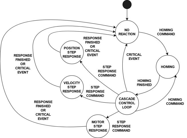
The control of a single servo stepper motor was implemented using a state machine diagram [5], in which each state corresponds to a single motor functionality. Transitions between individual states are shown in Figure 4. The state of control and holding position is the default state of the motor. There are also three additional states responsible for receiving step response of the motor and control system, homing and the state in which the motor has not been homed.
The initial state of the entire system is a no-reaction state, where it is impossible to perform any action except axis homing. This condition occurs after switching the power supply on or after performing a step test response. Homing was also based on a set of states and is done using the seek-and-feed method, similar to CNC (Computerized Numerical Control) machines. During homing, the axis moves quickly towards the limit switch (seek) and after encountering it moves away, then moves again towards it, but slower than before (feed). This procedure allows quick finding of the area where the limit switch is located and finding the exact position of this switch. When switch is found, the microcontroller resets the appropriate encoder register. To prevent contact vibration, the limit switches are equipped with additional debouncing capacitors. After homing, the motor enters the regulation state and maintains its position regardless of the forces and interferences. In order to maintain the set position, a cascade control system with an internal speed loop and an external loop from the position was designed (Figure 5). In addition, a feed-forward from speed and acceleration has been added to the control system [6]. The use of feed-forward improves the system’s dynamic properties and accelerates its response to setpoint change. In order to measure the speed, it was decided to differentiate the position from the encoder and pass it through a low-pass filter to eliminate high frequency noise [7].
While the encoder IC allows speed measurement, it has been shown that it is not suitable for the project because of too large measurement error and too large velocity oscillations. The control system uses nonlinear elements, improving the quality of regulation. The first one is saturation, which prevents the control signal from being too high. Saturation was placed at the output of both controllers of the cascade control system. The integrator in the velocity controller was equipped with an anti-windup filter. The last nonlinear component in the system is the dead zone, without which, due to the properties of the used motors, the axis would oscillate between two discrete steps.
The dead zone value was determined as +/- the value of one step after the transfer through the gearbox. Thanks to this operation, despite the occurring non-zero adjustment error resulting from the placement of the set point between two steps, the axis stably maintains the given position. During tests without a dead zone, it was shown that the control system on axes 2 and 3 is able to enter a state in which the system loses its stability.
From the regulation state, it is possible to home the manipulator again, or if it is in the configuration state, it is possible to obtain one of three step responses. Each step response sample is sent, as a standard functions response, and is secured by a checksum. After step response, it is possible to convert it to a CSV file, which allows further testing and simulation. Thanks to this it is possible to test the quality of control offline.
4.3. Safety Measures
The operation of control algorithms should be controlled and protected against unexpected events. For this purpose, three independent protections were applied in the microcontroller’s program. For each of them, the manipulator will interrupt the currently performed operation. Also, with each attempt to control, it will respond with a critical error frame with a description of where the event occurred. The first critical event is the loss of connection with encoders.
The second critical event concerns the state of limit switches. Switches can be pressed only at appropriate times during homing. If a low state is detected at any other time, it may mean that the switches have worn debouncing or someone has broken safety rules and is ding the allowable movement area of the axis. The algorithm doesn’t allow such movement but it is possible that the controller parameters have been incorrectly selected and the system has too much overshoot. In this case prevented by safety
In order to test the finished device, a dedicated PC application was written. The application allows control of individual axes of the manipulator,
If any of the encoders on the I2C bus fail to respond after a few attempts, the manipulator will stop.
The second critical event concerns the state of limit switches. Switches can be pressed only at appropriate times during homing. If a low state is detected at any other time, it may mean that the switches have worn out, something has happened to the debouncing capacitors, or someone has broken safety rules and is in the presence of a working robot.
The last event is related to exceeding the allowable movement area of the axis. The algorithm doesn’t allow such movement but it is possible that the controller parameters have been incorrectly selected and the system has too much overshoot. In this case collision is possible and should be prevented by safety measures.
5. Verification Tests
performance of homing procedure, updating the parameters of the control loop, and obtaining of step responses in jpg, png, bmp, pdf and csv formats. The state of each axis, its setpoint and process value , can be observed on graphs updated every 100ms or on displays.
In order to test the finished device, a dedicated PC application was written. The application allows control of individual axes of the manipulator, performance of homing procedure, updating the parameters of the control loop, and obtaining of step responses in jpg, png, bmp, pdf and csv formats. The state of each axis, its setpoint and process value, can be observed on graphs updated every 100ms or on displays.
5.1. Identification of Motor Dynamics
It was decided to carry out the identification of the control system using the engineering method. Using the program described in section 4, the system’s step response was obtained. It was determined that the system is astatic. It was decided to pe rform the identification of the system using two methods. The first one was to find static gain, system delay, and time constant and approximate using (2).

5.1. Identification of Motor Dynamics
It was decided to carry out the identification of the control system using the engineering method. Using the program described in section 4, the system’s step response was obtained. It was determined that the system is astatic. It was decided to perform the identification of the system using two methods. The first one was to find static gain, system delay, and time constant and approximate using (2).
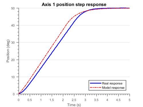
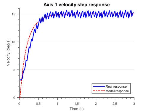
For example, assuming T=1, a gain K=0.0385 of and delay of T0 ~ 0.03 were obtained for the motor of the first axis. Due to the very small delay value, it was decided to round the e -sT0 ) to 1 to simplify the model. The second method was to use the tfest function available in the Matlab environment. The result of using the function was a first order system with free coefficient close to zero which was ignored. After ignoring the free coefficient both transfer functions were similar. From this point, dynamics received from tfest function were used. Comparison of the real response with model’s response is shown in Figure 6.

5.3. Tuning of Outer Control Loop
The outer control loop uses a proportional controller. The gain of the controller was chosen experimentally. For this purpose a small value of gain such as 0.1 was set and was slowly increased until a satisfactory dynamic of the system without any overshoot was obtained. Values of the feed-forward were set like in [8]; however, it was determined that the gain value of the acceleration was too great and must have been significantly decreased in the real device. Finally, it was found that the object exhibits the best dynamic properties with a proportional gain of 1.5, velocity feedforward gain of 0.6, and acceleration feed-forward gain of 0.2. In addition, it has been shown that the axles transferring the largest moments (2 and 3) suffered very badly from the presence of acceleration’s feed-forward gain and in their case the acceleration gain was set to 0. The final response of the first axis is shown in Figure 8.
5.2. Tuning of inner control loop
A PI controller was selected for the internal control loop. Tuning of the controller gains was carried out using the engineering method [9,10]. At the beginning, the proportional gain was increased to obtain satisfactory system stability, i.e. as fast as possible response of the system with low overshoot. After the appropriate value had been selected, it was reduced by half, and then the integrator’s gain was increased until system’s response was quick enough. Finally, the gain values were selected from the range of and . The dynamics of the internal loop of axis 1 is shown in Figure 7.
5. Conclusions
The research has shown that the robot’s movement is stable and there is no overshoot in position. The machine’s capacity was experimentally determined to be about 600 grams; however, the biggest limitation in capacity is the material that most of the manipulator is made of. In order to increase capacity, parts should be printed with more infill or should be redesigned. In addition, during tests of control algorithms it was shown that safety measures were working properly. A potential path for project development is to add a dedicated master device such as PC with Robot Operating System (ROS).
Authors
Mateusz Pająk – Gdańsk University of Technology, Faculty of Electrical and Control Engineering, Poland, Email: mpajak.main@gmail.com
Marcin Racław – Gdańsk University of Technology, Faculty of Electrical and Control Engineering, Poland, Email: mar.97.rac@gmail.com.
Robert Piotrowski* – Gdańsk University of Technology, Faculty of Electrical and Control Engineering, Poland, Email: robert.piotrowski@pg.edu.pl.
*Corresponding author
References
[1] L. Nocks, The Robot: The Life Story of a Technology, Johns Hopkins University Press, 2008, pp. 67–71.
[2] T. Sham, Autodesk Inventor Professional 2019 for Designers, 19th ed., CADCIM Technologies, 2018.
[3] L. Ball, “Make your own PC Boards,” Electronics Now, vol. 68, , 1997, pp. 48-51.
[4] Š. Kozák, “State-of-the-art in control engineering,” Journal of Electrical Systems and Information Technology, vol. 1, no. 1, 2014, pp. 7–8.
[5] M. L. Minsky, Finite-state Machines in Computation: Finite and infinite machines, Prentice Hall, 1967, pp. 11–31.
[6] M. Malek, P. Makys, M. Stulrajter, “Feedforward Control of Electrical Drives – Rules and Limits,” Power Engineering and Electrical Engineering, vol. 1, no. 1, 2011, pp. 35-42.
[7] A. Baehr, P. Mutschler, “Comparison of Speed Acquisition Methods based on Sinusoidal Encoder Signals,” J. Electr. Eng., vol. 2, no. 1, 2002, pp. 35–42.
[8] G. Ellis, “Feed-forward in position-velocity loops,” 20 Minute tune-up, Sept. 2000.
[9] J. G. Ziegler, N. B. Nichols, “Optimum Settings for Automatic Controllers,” ASME Trans., vol. 64, 1942, pp. 759–68.
[10] Ch. Grimholt, S. Skogestad, “Optimal PI and PID control of first-order plus delay processes and evaluation of the original and improved SIMC rules,” Journal of Process Control, vol. 70, 2018, pp. 36–46.


