7 minute read
Refrigeration


When recovering heat from a refrigeration system, you could allow the refrigerant to condense, or you can remove only a portion of the energy and desuperheat it. By Greg Scrivener
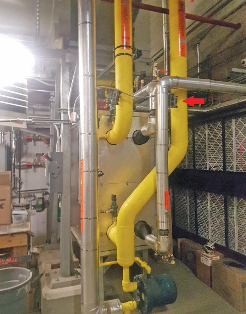
A desuperheating heat exchanger that controls the glycol portion of the heat exchanger to ensure that refrigerant is not condensed. The red arrow indicates the temperature probe used to measure the outlet temperature. The float can be seen on the bottom of the picture.
We’ve focused a lot lately on heat pumps where the purpose of the refrigeration system is heating. However, sometimes we want to recover only a small amount of heat. For instance, when heating a small space or preheating some make-up air or water, we don’t want to make things complex.
When recovering heat from a refrigeration system, you fundamentally have two choices — you can allow the refrigerant to condense, and the heat recovery heat exchanger becomes a condenser, or you can remove only a portion of the energy from the refrigerant and desuperheat it.
The choice between these two types of heat recovery systems is determined based on how
much energy you want to recover and what temperatures you need.
Condensing heat exchangers range from quite small, not even adding any appreciable condensing capacity to the system, to very large heat exchangers that perform all of the condensing for a plant. The limitation to a condensing heat recovery heat exchanger is that most of the energy is recovered at the condensing temperature, which we often want to lower in order to optimize the refrigerant plant's energy use. These types of heat exchangers also require more consideration in how they are installed as any condensed liquid needs to be drained somewhere (the high-pressure recovery or a lower pressure vessel).
Limitations
Desuperheating heat exchangers are limited to the amount of energy they can recover, but because the refrigerant enters at discharge temperature, they can achieve higher temperatures. Additionally, since there is no liquid at the outlet, there are not the same piping and installation limitations that come with condensing heat exchangers.
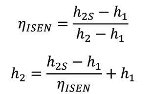
The question of exactly how much heat you can recover from desuperheating comes up frequently. The most complicated part of figuring this out is using the isentropic efficiency of the compressor to figure out the enthalpy (and therefore the discharge temperature) at the compressor outlet. Some compressor selection software takes the guesswork out, but we will lay out the fundamentals here.
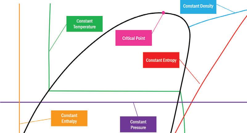
The discharge temperature at the outlet of a compressor depends on four main factors; in order to use this information to estimate the discharge temperature, you need to be familiar with getting information from a pressure enthalpy (ph – not to be confused with pH) diagram or refrigerant “steam” tables. Figure 1 shows the typical elements of a ph diagram — the refrigerant, the suction pressure and temperature of the refrigerant entering the cylinder, and the condensing pressure.
Determining enthalpy and entropy
First you use the pressure and temperature of the refrigerant entering the cylinder to determine the enthalpy and entropy of the refrigerant. Assuming perfect compression, the entropy of the refrigerant at the compressor discharge will be the same as the suction gas entropy. We use this information along with the condensing pressure to determine what the enthalpy would be with perfect compression. We know compressors aren’t perfect, and while this varies, a typical isentropic efficiency of a compressor is around 80 per cent. We can use the following to find the actual enthalpy of the refrigerant at the compressor outlet.
Then we can subtract the discharge gas enthalpy with the enthalpy of the refrigerant right when it’s about to condense. The
resulting value is the amount of energy that can be removed from the vapour by desuperheating. Figure 2 shows these data points represented on a ph diagram.
Figure 3 summarizes the results for three refrigerants at three different condensing temperatures. These are all completed with 30F superheat and no supplementary compressor or oil cooling. As you can see, there are several interesting features of this graph worth noticing. As you decrease saturated suction temperature (SST), a higher
Continued on page “35”

Figure 2: The enthalpy data points used to determine the enthalpy and temperature of the refrigerant at the compressor outlet and the amount of the total heat of rejection available.
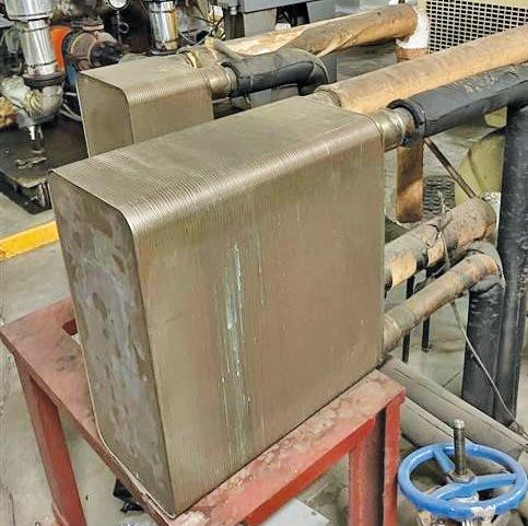
A pair of R507 brazed plate heat exchangers are connected to two refrigeration racks, which is used to heat process water The percent of the total heat of rejection that is desuperheating for R507, R448A, and R410A at 75F, 95F and 115F S.C.T.

Continued from page “33”
percentage of your total heat of rejection (THR) is desuperheating. The difference between refrigerants is significant. R410A, for example, has much more energy available in desuperheating than R448A or R507; it also has very high discharge temperatures when operated at low SST. While it is not typically a great refrigerant choice for freezer and low temperature applications, perhaps in a situation with heat recovery needs, it would be worth exploring.
Finally, as the condensing pressure decreases, the amount of heat available from desuperheating decreases substantially. It is slightly different in each case, but the amount of heat available from desuperheating decreases by about 50 per cent going from 115F condensing to 75F condensing. This is important because in many applications we want to ensure that there isn’t a lot of condensate in the desuperheater. Liquid in a desuperheater outlet can decrease the efficiency of the condenser and in extreme cases can cause excess pressure to drop if it is allowed to build in a vertical riser. There are also scenarios where liquid condensed in a desuperheater could cause a hydraulic shock (similar to water hammer) and damage the equipment or piping.
Making the right decision
This understanding leads us to a choice in the design. We can either do something to control the amount of heat being rejected by our desuperheating heat exchanger, or we can make the heat exchanger no more than approximately 25 per cent of the THR at the minimum load we expect on the system (you could refine this number using the calculations behind Figure 3). Both of these options are used frequently, and the decision depends only on how much heat you need.
Figure 4 shows a large desuperheating heat exchanger that is designed to maximize heat recovery. It has a temperature sensor and modulates the glycol flow to ensure that the refrigerant outlet temperature maintains at least 5F of superheat, which ensures that no condensation happens. It also has a float that will return any condensed liquid to a low side vessel if the controls malfunction or don’t react quickly enough and liquid refrigerant is produced. This heat exchanger is preheating outdoor air, so it was important to be able to maintain the temperature as high as possible.
Desuperheating heat exchangers is a good way of recovering a portion of the energy from our refrigeration systems. In many cases, they are less expensive to implement compared to full condensing heat exchangers and they can provide a simple and effective way to recover some energy. :
Greg Scrivener is the lead refrigeration engineer and a partner at Laporte Consultants, Calgary, and works throughout Canada and the U.S. He is a professional engineer and journeyperson refrigeration mechanic. He can be reached at GScrivener@laporteconsultants.com.

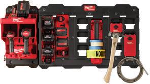
WALL MOUNT SYSTEM
CUSTOMIZE YOUR WALL. BUILD YOUR SYSTEM.

Bringing the versatility of PACKOUT™ into the shop, users will be able to fully customize their storage with wall plates, hooks, tool racks, tool holders, and a cabinet that connect with all PACKOUT™ solutions. Milwaukee® PACKOUT™ Modular Storage System now has over 65 solutions for users to choose from to fully customize their storage for site, transit, and shop, making PACKOUT™ the most versatile and durable modular storage system in the industry.
1 Choose Your Wall Plate Size 2 Choose Your Mounting Hooks, Holders And Accessories
A
Compact Wall Plate
B
Large Wall Plate BUILD YOUR SYSTEM.
SHOP
MILWAUKEE® PACKOUT™

SCAN MOST
VERSATILE DURABLE
MODULAR STORAGE SYSTEM


