2 minute read
Procedure Task 2
TASK 2
*Please use the following work procedure along with the machines’ safety and standard operation procedures.*
Advertisement
Milling process
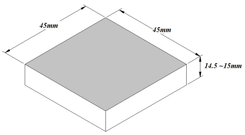
i) Measure the initial thickness of workpiece and thickness to be removed from workpiece. ii) Clamp the workpiece on the vertical milling machine. Position of all parts of milling
machine are as shown in the Figure 14. iii) Adjust the position of milling cutter facing the upside surface of workpiece. iv) Set the depth of cut (z-axis) position for milling cutter following the thickness to be
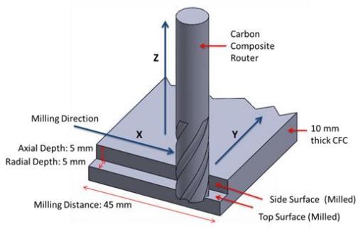
removed from workpiece. v) Do the face milling process on the workpiece in a way of layer by layer of side material
removal. Figure 15 illustrates the schematic diagram of how milling cutter cuts and
removes the layer of workpiece material during milling operation. vi) Repeat procedure (vi) to produce a workpiece with the dimension of 45 mm x 45 mm x
14.5 mm.
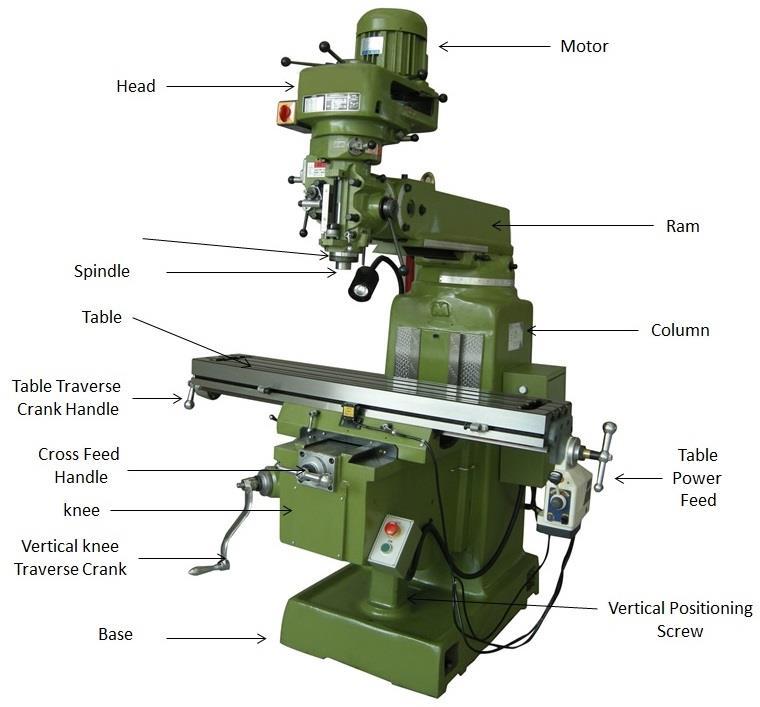
Figure 14. Parts of milling machine, 2015, Retrieved from https://www.mechanicalbooster.com/2016/12/what-is-milling-machine-operation-parts-types.html/
Figure 15.Schematic of milling cutter remove the materials of workpiece. (Dahnel A. N, 2015, p.3)
Surface grinding process
i. Identify the thickest dimensions on the workpiece.
ii. Place the workpiece on a worktable and switch on the magnetic chuck. The position of
workpiece and grinding wheel is illustrates in Figure 16.
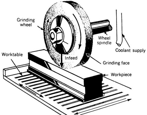
Figure 16.Illustration of workpiece position on worktable and the grinding wheel is place above the workpiece, 2012, Retrieved from https://engineerharry.wordpress.com/2012/04/21/grinding-machines-and-equipment/
iii. Switch on the grinding wheel. Be careful of spark ignition. Make sure operator of this
machine wearing a safety glass.
iv. Lift the worktable slowly until the grinding wheel hit the thickest spot on the workpiece.
When the workpiece produces a spark, it signs that grinding wheel hit the thickest spot
on workpiece.
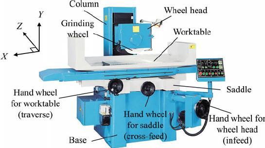
Figure 17.Parts of surface grinding machine shows worktable, wheel head and grinding wheel position on machine.(Girsang I.P. & Dhupia J.S.,2015, p.842)
v. Move the magnetic chuck forward or behind the grinding wheel if necessary; to avoid
continuous sparks ignition that might heat up the workpiece.
vi. Set up the coordinate z-axis as 0.000 at DRO surface grinding machine.
vii. Move the worktable of x-axis and y-axis to grind all surfaces of the workpiece. viii. Pull the worktable forward.
ix. Move the table in z-axis direction for about 0.020mm maximum.
x. Repeat step (vii) until the workpiece gain thickness of 14.00mm.
Figure 17 can be used as a reference to the position of all parts of surface grinding machine,
and guide to the surface grinding machine setup before the grinding operation take place.


