8 minute read
2.3.1. Seismic performance of masonry building


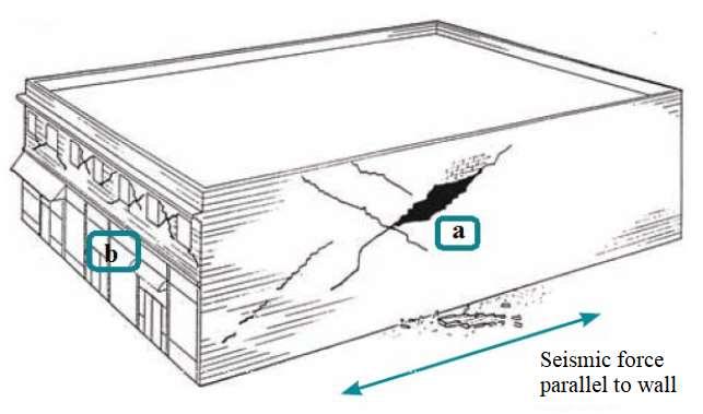
Figure 2-16 Collapse of the building due to seismic loads (Source: Guri, 2016)
Damages of the bearing walls of buildings with simple and complex masonry (with and without reinforcements) can be classified in three types (Guri, 2016), which depend on the cross-sectional size of the wall and the physical-mechanical characteristics of materials: 1. Damage caused by seismic shear forces (figure 2-17a, b) that is characterized by: Horizontal cracks according to the joints when the shear stresses are bigger than the allowable ones. Crossed diagonal cracks as a result of the main tension stresses are greater than the allowable one 2. Damage from compression with bending (figure 2-17c), which is characterized by the destruction of part in compression of masonry as a result of the reduction of its cross section after the horizontal crack in the tension area of the masonry.
Advertisement

Figure 2-17 Damage of masonry: from shear forces a) from main tension stresses b) from compression with bending c) (Source: Guri,2016)
2.3.1. Seismic performance of masonry building Masonry constructions only need to be assessed for their ability to withstand gravity loads if there is no threat of earthquakes occurring in the vicinity of the structure in issue In the event of an earthquake, on the other hand, the”structure will be subjected to a large number of cyclic horizontal actions, which will frequently result in large additional bending and shear stresses in masonry”walls, which can frequently exceed the elastic range of the behavior of masonry materials in the event of an earthquake. It is inevitable that building structures will be damaged by seismic loads. When they're not designed and detailed sufficiently to resist deflections and release energy, the resultant inertia forces can cause significant damage or perhaps even destruction of the structure.”Because of the usual structural structure and reserve in strength of masonry materials when it comes to supporting vertical gravity loads, it is not often essential to assess the load-bearing capacity of masonry walls and floors for vertical seismic”action. However, due to the uniformly distributed of walls in both transverse directions, the geometrical criteria for shear walls (effective elevation, thickness, and location of openings), and the connection among floors and walls, out-of-plane resistance to earthquake motions is typically not an issue.”Only severe spans between structural walls that exceed the code-recommended values are required to undergo seismic resistance testing for lateral out-ofplane loads,”as a result of which only extreme spans between structural walls are tested. When subjected to in plane seismic stresses, the seismic behavior of structural masonry walls can be categorized into three categories of processes and failure modes, based on the findings of earthquake damage analysis and subsequent experiments. The processes are dependent by the shape of the wall 61
(altitude ratio) as well as the type of materials, but they are also influenced by boundary constraints and stresses pressing on the wall, among other factors. (Tomazevic, 1999). Seismic stresses are frequently responsible for the splitting of walls into two parts, as well as”the sliding of the upper half of the wall along one of the horizontal mortar joints, particularly in the case of walls with a low vertical load and poor-quality”mortar. Sliding shear failure is the term used to describe the failure mechanism. Unless the vertical load and axial compression stresses in the wall are significantly more than the typical limits, the wall is likely to break in shear or bending, depending on the conditions of the situation. It occurs when the”principal tensile stresses developed in a masonry wall as a result of a combination of vertical and horizontal loads exceed the tensile strength of the masonry materials”used in the wall's construction. Shear failure is one of the most common modes of failure for masonry walls subjected to seismic loads. The development of characteristic diagonal fissures in the wall occurs shortly before the achievement of lateral resistance. In some cases,”the cracks can follow the mortar joints,”in others they can penetrate through the masonry units, or in other cases both. Although”better shear resistance and a high moment/shear ratio are desirable, crushing of compressed zones at the”extremities of a wall is almost always observed, indicating that the wall has failed in the flexural mode (Tomazevic, 1999). It is difficult to”model the non-elastic, non-homogeneous, and anisotropic nature of brickwork using mathematical equations alone. Predictions of the lateral load-bearing capacity and deformability of masonry walls”are frequently made by drawing parallels between masonry walls and reinforced concrete structural members. Because the behavior of reinforced grouted masonry and concrete under seismic loads is nearly identical, only minor modifications are required”in the case of reinforced grouted masonry.”In the case of completely grouted masonry walls,”good agreement with experimental data can be obtained by employing general computer programs”for forecasting the inelastic cyclic behavior of reinforced concrete structures (r.c. structures) (Shing, Schuller, & Hoskere, 1990). To account for the mechanical features of traditional ordinary or strengthened masonry construction, mathematical models initially created for reinforced concrete elements must be adjusted to account for the unique particular mechanical qualities of masonry materials. In order to better understand lateral loaddisplacement connections, numerous different physical models have been used to create simulations. Researchers have considered a combination of arch and truss mechanisms as well as a “combination of dowel, pullout, and friction mechanisms in order to predict the lateral load-displacement skeleton curve in the case of shear failure of reinforced masonry walls, as well as cyclic hysteretic”behavior. On the basis of experimental data from cyclic testing of strengthened masonry walls, a global implied dimensionless mathematical stress - strain model has been created (Bernardini, Giuffre, & Modena, 1984). The hysteretic behavior of simple brick walls that fail under shear has also been characterized using parameter functions, such as the shear modulus and its viscous equivalent, which were both determined by testing on the structures (Tanrikulu, Y, & McNiven, 1992). A new seismic code has been introduced recently that incorporates limit states verification of masonry structures' seismic resistance, which has been in use for many millennia and has been used for decades with permitted stresses methods. When it comes to designing masonry structures, the philosophy behind Eurocode 6: “Design of masonry structures” (EC6-1, 2008) and Eurocode 8: “Design provisions for earthquake resistance of structures” (EC8-1, 2004), both of which governs the design and implementation of masonry structures, is founded on the basic necessity of creating a structure in such a way that it will stay in use with a reasonable probability for the estimated lifetime – and under the predicted service conditions. That implies that the building must be capable of resisting all actions and forces that may occur over its lifetime without suffering significant damage, but it should also be able to avoid being damaged disproportionally in the event of an accidental event such as an explosion, an impact, an earthquake, or a human error. In seismically active areas, two fundamental needs are taken into consideration throughout the design process: the demand for no collapse and the necessity for damage limitation. Construction of the structure should be such that it can sustain the design seismic action without experiencing local or widespread collapse. Additionally, the structure should retain its structural stability and load-bearing ability during an earthquake of estimated intensity (design earthquake). If the building is exposed to strong actions that have a greater likelihood of occurring than the design earthquake but are less intense, no damages to architectural or non-structural elements shall occur, which would prevent the structure from being used or would result in costs that are disproportionally 62
high compared to the design earthquake. As a result, in order for a structure to withstand seismic loads, it is necessary to verify two fundamental limit states, which correspond to the criteria listed above: • “Ultimate limit state, which is associated with collapse or other forms of structural failure that may jeopardize the safety of people”, and • “Serviceability limit state, which is associated with the occurrence of damage, deformations, or deflections that exceed the point at which the specified service requirements of the building are no longer met by the structure”. Seismic and design response spectre There are many different ways to describe seismic action, including ground acceleration or velocity time-history (either recorded or artificial), and response spectrum (to name a few). According to the relevance and complexity of the structure under consideration, the type of seismic action to be used in seismic verification would vary (Tomazevic, 1999). When considering seismic ground motion, it is necessary to take into account its tridimensional nature in some instances. However, when the regularity of masonry structures is taken into consideration, the response spectra representation will provide appropriate results in the vast majority of masonry construction scenarios. Ground acceleration or velocity time-history constitute the most direct form of representation of seismic activity, and it is used to compute the structural response and, consequently, the impacts of the seismic action on the ground. On the other hand, response spectra presuppose the computation of the structural response in advance. Calculating action effects is only necessary when design seismic loads are estimated using response spectra. The only method available for obtaining accurate information on the current response of a masonry caused by earthquakes loads is direct non-linear dynamic analysis, which considers the non-linear properties of masonry structural elements. To avoid the more complex “direct non-linear dynamic analysis,” the structure's non-linear behavior and “energy dissipation capacity” are considered “by performing a simple linear elastic analysis” (Tomazevic, 1999) but accounting for a reduced response spectrum, referred to as a design spectrum, which is obtained by introducing the behaviour factor, i.e. force reduction factor q. Behaviour factor Despite the widespread belief that masonry is a brittle structural material, investigations and study of seismic damages have showed that even simple masonry structures have a very high energy dissipation capacity, allowing elastic seismic stresses to be reduced. The well-known concept of behavior factor q (force reduction factor) is summarized in figure 2-18, which compares the seismic response envelope curve of an actual building, idealized as a linear elastic - perfectly plastic envelope, to the response of a perfectly elastic structure with the same initial elastic stiffness characteristics..
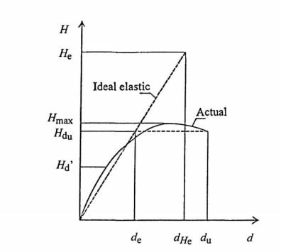
Figure 2-18 Definition of structural behaviour factor q (Source: Tomazevic,1999)
63


