23 minute read
2.4.2. Seismic retrofit
, CO2-, and particularly material-intensive process. Thus, the total energy balance becomes positive after approximately two to three years (energy payback period), depending on site-specific factors such as collector type and sun intensity.” Technologies for heat pumps Heat pump technology enables low-energy heating requirements and cost savings. b. Cooling technologies The purpose of space cooling methodologies (JRC (Joint Research Centre), 2012) is to reduce demand by utilizing many “of the following techniques: - heat absorption during the daytime in summer by increasing the amount of heat sinks; - usage of cool roofs (reflecting incoming solar radiation); - green and brown roofs (cooling by evaporative absorption).” - Passive cooling This method allows for cooling without the use of mechanical devices that use energy. To this end, the urban microclimate has a significant impact on the effectiveness of passive cooling solutions via the following: -
“Optimal insulation, shadings, and overhangs, as well as air change rate. Integrated designs that account for internal heat gains throughout the summer and how to dissipate this heat to the surrounding environment should be” thoroughly examined.
Advertisement
Renewable technologies The use of the renewable energy sources is the most appropriate technology concerning environmental management. Heat pumps and geothermal systems make use of renewable energy sources such as “aerothermal, hydrothermal, and geothermal, but they still require considerable amounts of conventional energy (usually electricity) to function.”
2.4.2. Seismic retrofit By definition, "repair" refers to the post-earthquake restoration of damage produced by earthquake ground motions that does not significantly raise a structure's seismic resistance over its preearthquake state. However, "strengthening," "seismic strengthening," or "seismic upgrading" refer to technological changes in a building's structural system that increase its strength and ductility. As per the recommended nomenclature (Todd, 1994), reinforcing a structure prior to an earthquake is referred to as "rehabilitation," while strengthening a structure following an earthquake is referred to as "retrofit." Thus, the decision to repair a structure following an earthquake or to enhance it in advance of an earthquake is contingent on the structure's seismic resistance. Many existing buildings, both non-engineered and engineered, that are considered "old" by earthquake-resistant design standards, rather than simply by construction age, collapse or sustain severe damage, as demonstrated by all recent earthquakes. Modern buildings (such as masonry structures) designed to meet the demands of state-of-the-art seismic design effectively resist strong ground motion. Due to the fact that older masonry structures are typical examples of non-engineered traditional construction, their seismic susceptibility is generally quite significant. Indeed, the majority of earthquake damage and fatalities in these locations are caused by the insufficient seismic behavior of existing masonry structures, most commonly residential residences in urban and rural areas constructed in the conventional manner. Seismic retrofitting entails several unique considerations in comparison to static load strengthening or energy efficiency upgrades. For a good seismic upgrading, three separate characteristics of a structure must be examined and well-coordinated: “stiffness, ultimate resistance, and deformation capacity” (Sigmund, 2019). When contemplating seismic retrofitting, it is important to avoid retrofit schemes that are too focused on a single distinguishing “feature of a structure without” taking into account the potential negative repercussions of the other aspects. When retrofitting an existing structure for seismic protection, “one or a combination of the following” measures should be applied (Uihlein & Eder, 2010): • “Improving the building's regularity” • “Reinforcing structural parts” • “Increasing ductility by avoiding brittle failure” 69
• “Softening the structural system by reducing its rigidity” • “Damping the building's foundations” • “Changing the building's use”
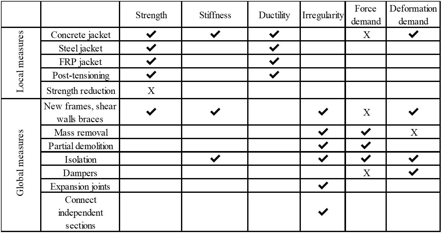
Measures and criteria for retrofitting In a recent report from the JRC, they talked about how to make existing RC buildings less likely to be damaged by earthquakes. It is said that structural assessment is used to find problems in existing buildings. This is proceeded by the identification of the best measure or mixture of initiatives to enhance the performance of the building. In Tsionis et al. (Tsionis, Apostolska, & Taucer, 2014) , they came up with a list of the most widespread retrofit measures and the characteristics they influence. This was based on the two main goals of repair and strengthening (reducing demand or increasing capacity) and the three major response characteristics (strength, stiffness, and deformation capacity) (Table 2-7). It has been shown that some actions have an effect on more than one thing about the structure, and one of them could have an unwelcome effect. An increase in rigidity, for example, could result in “higher force demands that could exceed the as-built capacity of some parts.”
Table 2-7 The effect of local and global retrofit initiatives on the physical attributes of buildings (Source: Tsionis G, Apostolska R and Taucer F, 2014)
A suitable retrofit design is typically evaluated in terms of vertical components (e.g. columns, walls, braces, and so on) because of the importance of vertical components in providing lateral stability and resistance to gravitational load transmission. Large inter-story deflections cause vertical element failures because they impose excessively high force or displacement demands on the structural members. It is possible that walls and columns are strong enough to sustain seismic and gravity stresses, but the structure as a whole is inadequately connected, creating the risk of partial or complete collapse during an earthquake, depending on the kind of building. To develop an effective retrofit scheme, it is critical to have a complete understanding of the existing building's predicted seismic reaction and all of its flaws. In the classical sense of enhancing the performance of an existing structure, there are three fundamental types of retrofit measures (FEMA 547, 2006): Increase the strength or rigidity of an element by adding components. Enhance current elements' performance by boosting their strength or deformation capability. Enhance component connections to ensure “that individual elements do not detach and fall, that a complete load path exists, and that the designer's force distributions” can occur.
70
Along with enhancing the strength or ductility of existing structural parts, there are less conventional approaches for enhancing the entire structure's performance. These techniques can be classified as follows: Seismic demand can be lowered by eliminating upper floors or other bulk from the structure, installing dampening devices to limit displacement, or seismically isolating the entire structure or portions of it. Selected elements can be eliminated or weakened in order to avoid detrimental interactions between different systems, to prevent element damage, or to minimize vertical or horizontal irregularities.
Strategies for Developing Rehabilitation schemes Consider the Technical Aspects A retrofit designer's initial review should focus on the issues found during the examination. Certain frequent seismic defects are extremely localized and can be effectively remedied by targeting retrofit efforts narrowly. It is quite usual to add strength or stiffness, and a few new pieces may resolve issues with strength, drift, and configuration. Review that the revised structure will (FEMA 547, 2006): Possess a comprehensive load path Possess the necessary strength and rigidity to conform to the design standard Compatibility with and protection of the current lateral and gravity systems Have a suitable foundation to support a permanent base structure, or have considered foundation flexibility appropriately in the design
Considerations of a Non-Technical Nature The retrofit option is nearly typically guided by building-user concerns rather than purely technical requirements. Five fundamental challenges [108] concern building owners and users: Cost of construction Performance during earthquakes Disruption of occupants in the short term The building's long-term usefulness Aesthetics, taking historic preservation into account Structural weakening as a result of dynamic loads, foundation sinking, planar and off-plan deformations of the wall, can lead unreinforced masonry structures to collapse. Unreinforced masonry buildings are in the future dangerous structures for human life due to the fragile nature of their structural elements, therefore their level of performance must be determined (figure 2-20). Different countries organizations dealing with these problems like Federal Emergency Management Agency (FEMA) in USA, which define the damage to unreinforced masonry structures during an earthquake.
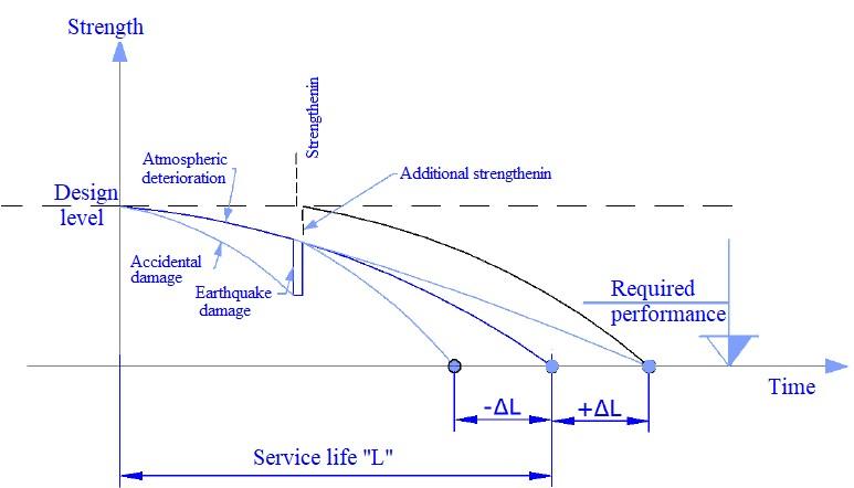
Figure 2-20 Level of performance of structures (Source: Guri, 2016)
71
Strengthening of masonry with structural elements in critical parts There is a wide variety of intervention techniques for strengthening and repair of masonry structures, which have suffered damage due to degradation, overload, basement sinking, change of temperatures, natural disasters such as wind, earthquake, etc. These techniques are divided into "traditional" and "modern". "Traditional" techniques use materials and construction processes that are originally used for structure construction, while modern techniques aim more efficient solutions using new materials and technologies. Here are some of the most commonly used reinforcement techniques (Biondi, 2014): “Traditional” o Demolish-rebuild intervention. o Placement of concrete belts. o Installation of steel tie rods. o Reinforced injections. o Reinforcement of openings with metal profiles in the form of boxes. o CAM systems etc.
“Modern” o Reinforcement with composite materials FRP (Fiber reinforced polymer), o Reinforcement with composite materials TRM (Textile-Reinforced-Mortar) Fiber-reinforced composites (FRCs) have been used as building materials for more than 3000 years, according to historical records. The use of straw in clay bricks is one of the most well-known examples. Other natural fibers are used to reinforce the walls of mud in order to increase the strength and ductility of building materials. Combination of polymers as high strength materials but with low stiffness with the fiber of high stiffness and high strength, has made possible their use in a large number of applications to increase and improve the structural performance. These include uses in high carbon fiber technologies in resin systems (CFRP) for aircraft parts and sporting goods or Fiberglass Reinforced Glass (GFRP) systems for car parts and boat gear (Guri, 2016). In civil engineering it has been an ever-increasing use of composites FRP for rehabilitation and reinforcement of reinforced concrete, metal elements and wooden, etc. The purpose of their use in the structure is to increase: o Compression & tension capacity o Shear capacity o Bending capacity o Stability of the elements o Ductility o Stiffness o Durability of constructive materials o Lifespan of the structure
Their application is also done on these purposes (Guri, 2016): 1. Changing non-structural elements into structural elements. 2. Eliminate structural problems, which are the result of excessive stresses on of structure that can be caused by overload, fire, foundation sinking, corrosion phenomena, effects of fatigue, chemical actions, agents atmospheric etc. 3. Allow feasibility in changing the function of a structure. 4. To correct possible errors in the design and construction of the structure. 5. Improve environmental conditions, which have not been properly understood during design phase.
Installation of reinforcing concrete or metal elements To strengthen masonry objects must be well understood the way of their collapse under the action of seismic loads. Structural damages very often are not identified as such, and light repairs have been undertaken, which hide obvious damages. Therefore, the repair strategy should include design for the current situation and structural requirements in order to achieve an acceptable level for structure 72
safety. To analyze the causes that favor damage to a building without antiseismic masonry belt during seismic action, we study a section of it (figure 2-21). It is composed of two systems orthogonal walls A and B. In those buildings where, for reasons of poor implementation and lack of antiseismic bands, the connection between the structural walls is weak, and the behavior of the walls is different. Thus, in the first sequences of seismic events, the wall of one direction always tries to push the wall of the perpendicular direction to it. For these reasons it becomes inevitable their detachment in the contact area, by causing the development of vertical cracks in any of the corners of the wall or near the bottom, as the tensile strength from bending outside the plane is insufficient (figure 2-21a). In these conditions the walls on which the seismic force acts perpendicular to their plan (walls A), will swing independently of the other perpendicular walls to them (walls B). In these cases, the walls resist the inertia force, mainly by their bearing capacity in bending. Walls subject to seismic forces according to their plan have a greater resistance, because also the stiffness to this direction is larger, (the mode of damage will depend on their geometric dimensions, height to width ratio and physicmechanical characteristics of construction materials). A typical damage is horizontal cracking that spreads along the mortar joint as a result of horizontal sliding (figure 2-21a).

Figure 2-21 Typical damages: a) without antiseismic bands and flexible slab; b) with antiseismic bands and flexible slab; c) with antiseismic bands and rigid slab (Source: Guri, 2016)
It is known that one of the essential requirements in antiseismic design, is that the intersection slab must act as a rigid horizontal diaphragm, well connected to the vertical supporting elements (figure 2-21c).
Effects of antiseismic band on masonry objects We will analyze these structures again by referring to a section element of the building, consisting of perpendicular faces well connected between them, in the present conditions of a rigid slab or antiseismic belt (figure 2-22).

Figure 2-22 Seismic action to a section of the building with a rigid slab or antiseismic belt (Source: Guri, 2016)
As can be easily distinguished, the walls A are the ones that will withstand mainly horizontal seismic forces, which represent: The masses of the respective slabs which are transmitted to walls A through the connections that exist between them and concrete bands. o Loads of walls B transmitted to walls A. o The mass of the walls A and B located in the upper and lower half and of the story that we are studying. The presence of r.c. belts at the interstory level, makes the walls vibrations to be synchronized. However, it should be noted that even in this case it still exists the possibility of bending outside the plane of the walls, which is associated with the reduction of resistance of the structure as a whole.
73
Installation of concrete bands This intervention is performed through the adding of a structural element that will act as s concrete belt. It can be realized at floor levels or on top of building. It can be applied in those cases when efficient connections between walls or between walls and horizontal floor / roof structures are missing. It encourages the behavior or concept "box" by creating a continuous link between structural elements (walls, floor-walls, wall-roof). When applied in the upper part e of structure, it limits the bending of the walls outside of his plan. Improving "box" behavior is difficult to measure with numbers. Intervention, if well implemented, enables the prevention of local collapse mechanisms. If performed at the top of the structure reduces the length of the free refraction of the upper part of the wall faces.
Surface Treatment Surface “treatment is highly regarded due to the fact that it may be carried out by untrained laborers. The method begins with the exterior of the structure being covered with a steel or polymer mesh that has been coated with a layer of high-strength mortar. This strategy boosts the out-of-plane resistance of masonry structures by increasing the height-to-thickness ratio of the walls,” hence reducing any arching movement (Smith & Redman, 2009). This procedure involves a variety of strategies: (1) Reinforced mortar (2) ferrocement, (3) reinforced plaster, and (4) shotcrete.
Reinforced mortar is realized by placing a metal mesh in the surface of the wall which is then filled with mortar. Instead of wire mesh, can be used another high resistance material with adhesion which is bonded to the masonry via steel straps (5 every 4m2 wall surface). It is the right intervention for walls in advanced degradation condition (when we have complex and widespread cracking) and in cases where it is required a significant increase in resistance. It increases resistance and ductility without modifying of the wall, reduces cost and has easy execution. The intervention also presents disadvantages: modification of rigidity, increase in mass; change in the external appearance of the wall. The efficiency of the intervention is closely related to the capacity of the transverse connectors for transmitted forces. It is not advisable to apply only to one side of the wall.
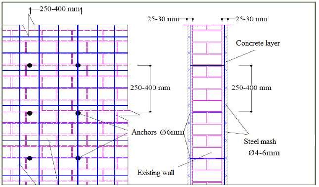
Figure 2-23 Reinforced mortar (Source: Guri, 2016)
This intervention involves insertion with pressure in the composition joints, depending on the state of wall degradation, in the existing openings in order to improve the mechanical characteristics of the wall. It can be applied in the presence of widespread cracks and for walls with internal voids and good mechanical properties of aggregates (although damaged). It is a "passive" intervention that guarantees an increase in resistance and improvement of local damage without changing the balance and external appearance of the wall and improves the mechanical characteristics of the wall.
74
The effectiveness of the intervention is closely related to its ability to spread the mixing. It is nevertheless important to conduct mechanical tests on the existing wall in site to check if the material reached the required values of design resistance. An easy and fast control can be achieved through ultrasonic tests.
Ferrocement is a type of concrete composed of wire mesh and cement mortar. “It may be reinforced with mesh totally embedded in a high-strength cement mortar” at a ratio of 4–9%, as seen in Fig. 224(a). The fundamental downside of ferrocement is that the reinforcing materials corrode due to the mortar's insufficient covering of the metal. Additionally, tying the wire meshes and rods together takes time. Another popular way for strengthening URM constructions is reinforced plaster, which includes covering the walls “with RC layers. This procedure begins with the placement of a mesh of reinforcing bars on the wall's faces and the subsequent layering of reinforced faces with concrete (Fig. 2-24(b)).” Finally, shotcrete is a method that includes shooting “cement mortar or cement concrete onto the masonry surface using a nozzle. Impinged shotcrete forms a uniform pile on the wall. The injured member's surface and the shotcrete layer are glued together using an appropriate epoxy adhesive. Shear keys are used to ensure shear transfer between the old and new” concrete layers. The addition of fibres increases the tensile strength and toughness of the material. Fig. 2-24(c) illustrates the process schematically.

Figure 2-24 Techniques for surface treatment include the following: (a) ferrocement; (b) reinforced plaster; and (c) shotcrete.
Reinforcement of masonry with FRP composite materials Advanced composites are used as reinforcing materials of masonry structures from several decades, in the form of laminates, mesh and strips. These reinforcements of masonry structures increase their bearing capacity in bending as well in and out of the plane, against the seismic loads. One of the main drawbacks associated with the adaptation of structural elements is the choice of FRP configuration as well as the dimensioning of their elements (FRP cross section) for obtaining the required resistance (CNR (Commissione Nazionale Delle Ricerche), 2013). Masonry structures are very common and built-in different time periods, they need strengthen interventions because they accumulate technical problems and present difficulties for their utilization. Their technical problems associated with inappropriate materials and techniques, the action of seismic and wind loads, basement sinking and atmospheric conditions, or the need to increase bearing capacity responding to the demands of new seismic codes, or their change in function. "Traditional" methods of improving masonry structures are mentioned above. Of course there are disadvantages with some of the above mentioned techniques like: increasing thickness and mass from coating with reinforced concrete layer, difficulty in their implementation work, have made researchers study technology with modern material; using as reinforcement the polymer fibers, commonly known as FRP (Reinforced Polymer Fiber). These typical materials are
75
made of carbon fiber (CFRP), glass (GFRP) or aramid (AFRP) joined by polymer matrix (epoxy), which are produced and combined for a variety of properties (Hollaway & Teng, 2012).
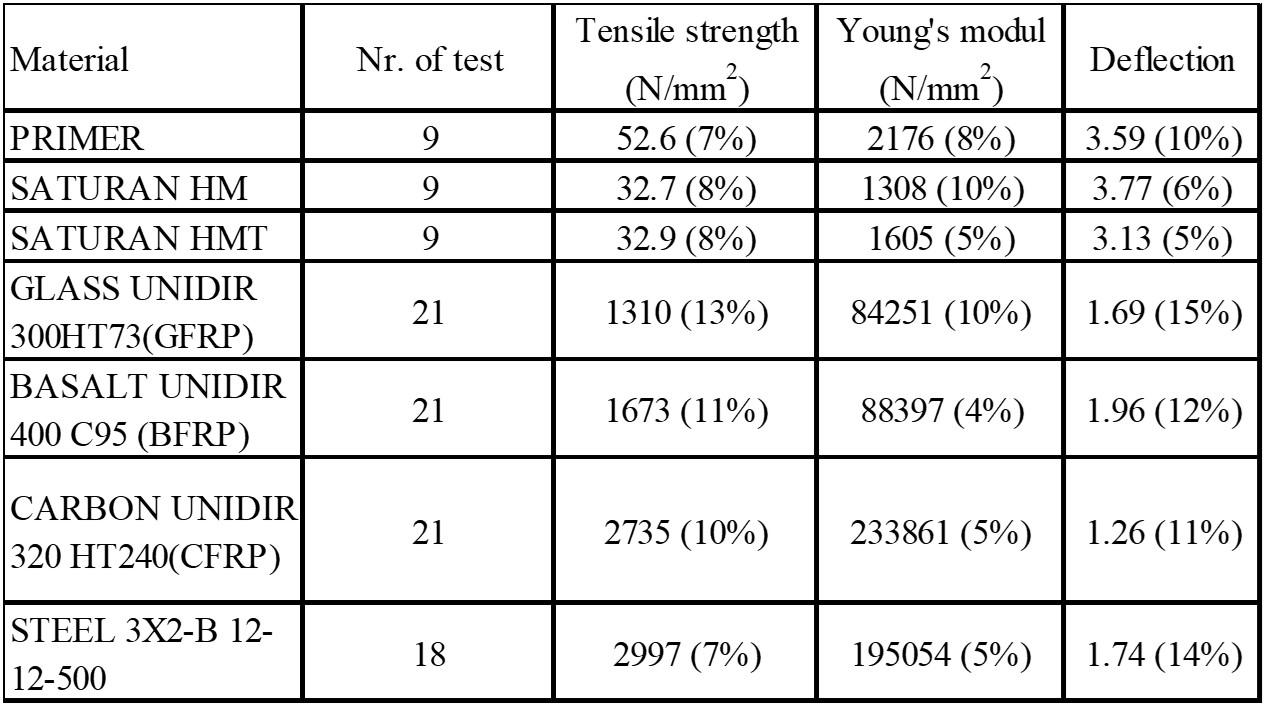
Polymer Fiber Reinforcement (FRP) Materials Some definitions have been made for “the meaning of advanced composites polymers. A clear essential definition of their meaning is given in 1989 by a study of the group of the Institution of Structural Engineers, who defined an advanced polymer composite for construction industry as follows:” "Composite materials normally consist of two discrete phases, a matrix of continuous which is often resin, surrounding a reinforcing fibrous element. Reinforcement has high strength and stiffness, as the matrix binds the fibers together, allowing the strain to be transferred from one thread to another by produced a consolidated element. The orientation of the fibers is to safely withstood high mechanical stresses. In the anisotropic nature of these materials lies their great advantage; the reinforcement can be adapted and oriented to follow the stress patterns in the main element, which makes a more economical compared design than the design with traditional isotropic materials. Reinforcements are usually glass fiber, carbon or aramid. Resins which must carry distinctive properties such as chemical or thermal resistance” (CNR (Commissione Nazionale Delle Ricerche), 2013). Structural composite polymers have a wide range of mechanical properties. These properties depend on: o the relative proportions of fibrous materials and matrix (volume / weight ratio of fiber / matrix) o mechanical properties of components (a set of carbon fibers will give greater rigidity than a set of glass fibers in the same amount) o production method o fibrous orientation within the polymer matrix (fiber orientation can take shape without one direction, in two directions and randomly oriented fiber groups) Use of FRP system in masonry structures is normally part of the global structural interventions. The basic role of the FRP system is the transfer of tensile stresses both within a structural element and between structural elements. The new greater tensile strength modifies the reaction of the structure to external loads. In particular, the FRP system in the masonry structure can be used in: o Increasing the bearing capacity and durability of the walls. o Transformation of structural elements into supporting elements by increasing strength. o Restricting in the opening of cracks. o Wrapping columns to increase their strength and ductility. Physical-mechanical characteristics of FRP The data on physical-mechanical properties of reinforcing materials in this study are obtained from the experience of working in groups of twelve laboratories from European universities with RILEM, Technical Committee 223-MSC “Masonry Strengthening with Composite materials”. Below (table 2-8 and 2-9) we give a summary study test results for GFRP (Glass Fiber Reinforced Polymer) and CFRP (Carbon Fiber Reinforced Polymer) (Valluzzi, 2012).
Table 2-8 Mechanical properties of primer, resin and fibre from tension test (Source: Valluzzi, 2012)
76
Table 2-9 Physical-mechanical characteristics of fibre (Source: Valluzzi, 2012)
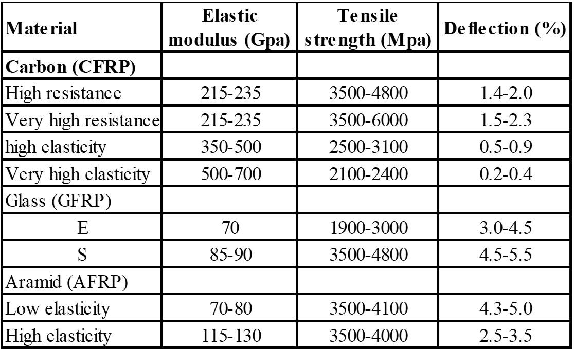
Matrix The matrix, by its shear strength, must allow conduction and distribution of stresses in fibers. It protects the fibers from physical - chemical attacks, that come from the environment. Also, it connects the fibers to each other, opposing disintegration of the fibers. The matrix (bonding material) can consist of polymers, metals, ceramic materials. Polymer matrices are more spreads, because they have high tensile strength, high resistance to corrosion, low weight, are simple in realization. In their initial unmixed state, these matrices have low viscosity, facilitate the process of manipulating them. They have very good bonding properties and good resistance to atmospheric agents. The downsides of these resins are sensitivity to ambient temperatures and sensitivity to moisture in the phase of preparation. In the study we will refer only to polymer matrices. Depending on the type of fiber used FRP are divided into (CNR (Commissione Nazionale Delle Ricerche), 2013): GFRP (Glass Fiber Reinforced Polymers), with fiberglass; CFRP (Carbon Fiber Reinforced Polymers) with carbon fiber; “AFRP (Aramid Fiber Reinforced Polymers), or ARP (Aramide Reinforced Polymers)” with aramid fibers etc.
Adhesive material Preparing a FRP reinforcement requires the use of adhesives. The choice of the right type of adhesive, as well as the surface treatment where the FRP will be placed, depends mostly from the type of FRP as well as from the element where they will be placed (e.g., reinforced concrete, metal, masonry, etc.). The FRP technical files also contain the type of adhesive material that is recommended to be used. The market offers several types of materials adhesives with different chemical bases, such as polyester, acrylic, etc. Epoxy resins have better properties than other adhesives. Epoxy resins used as adhesives have these disadvantages: are sensitive to environmental conditions (temperature, humidity, etc.) and are sensitive to fire.
FRP reinforcement systems The reinforcement design should aim at absorbing stresses in tension in the FRP system. The FRP system that is subject to compressive stresses does not have direct impact on the masonry structure as their cross-sectoral area is negligible compared to that of a structural element. Structural modeling of a masonry structure is a complex job. Distribution of forces and moments within a structure or the distribution of stresses in a single element of the masonry structure can be calculated by linear elastic analysis or by nonlinear analysis for the inelastic behavior of the masonry material. All available types of FRP materials can be used for reinforcing the masonry structure. However, it is generally believed that fiberglass polymers are more preferred than other types of FRPs in strengthening masonry, not only because of their low cost but also of the small module of elasticity,
77
which connects it to the masonry and prevents premature detachment of reinforcement after small critical cracks in the masonry (Hollaway & Teng, 2008). FRP can be used for masonry reinforcement in different systems (figure 2-25): o FRP laminate system: carbon (CFRP); aramid (AFRP); glass (GFRP). o FRP mesh system: glass (GFRP); aramid (AFRP); carbon (CFRP). o FRP rod system, NSM (Near Surface Masonry) reinforcement: glass (GFRP); aramid (AFRP); carbon (CFRP). o Global reinforcement system: carbon (CFRP); aramid (AFRP); glass (GFRP).
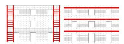
Figure 2-25 FRP system application for masonry reinforcement (Source: CNR, 2012)
Reinforcement with TRM (Textile-Reinforced Mortar) The application of external reinforcement with TRM is considered as an alternative method of FRP (Fiber-Reinforced Polymers). This alternative method, called TRM (Textile-Reinforced Mortar), consists of a FRP mesh attached to the inorganic matrix masonry, cement mortar (Papanicolaou, Triantafillou, Karlos, & Papathanasiou, 2007). This technique combines the good sides of both interventions ("traditional" and "Modern") through the use of textiles in the form of knitted fibers (mesh), glued to the surface of the structure with cement- mortar replacing the organic adhesive (resins), which are very expensive compared to cement-mortar. Use of an inorganic material as adhesive instead of an organic adhesive, eliminates its disadvantages such as: low properties at high temperatures, high cost, difficulty painting the masonry surface, lack of recycling.
TRM (Textile-Reinforced Mortar) materials Textile-reinforced mortar consists mainly of from two materials: (1) cement mortar adhesive and (2) textile mesh produced with FRP reinforcing fiber. The success of reinforcing and adapting the structure by using TRM, depends on the properties of these two components of TRM (Papanicolaou, Triantafillou, Karlos, & Papathanasiou, 2007).
Physical-mechanical characteristics of TRM Data on the physical-mechanical properties of reinforcing materials with TRM for our study are taken from the study of Papanicolau C. (Papanicolaou C. , 2010) and laboratory tests performed e University of Patras, Greece. The most commonly used fibers and physico-mechanical properties for TRM fabrication are given in table 2-10 and 2-11 (Papanicolaou C. , 2010).
78


Table 2-11 Result of test in compression and tension for mortar (Source: Papanicolau, 2010)
Samples
Physical properties (Mpa) Age of the cube (days) 1 2 3 4 average
Compressive strength 7 37.32 34.04 35.88 36.4 35.91 28 51.5 52.1 50.9 54.1 52.2 3 2.4 2.1 2.4 2.3 2.3 Tensile strength 7 2.8 2.9 3.8 3.7 3.16 28 4.46 4.3 4.33 4.51 4.4
TRM reinforcement systems TRM can be used for masonry reinforcement in the same way as FRP, replacing organic adhesive with inorganic adhesive (cement mortar): o FRP laminate system: carbon fiber mesh (CFRP); aramid (AFRP); GLASS (GFRP). o FRP rod system, NSM (Near Surface Masonry) reinforcement: glass rod (GFRP); aramid (AFRP); carbon (CFRP). o System against the mechanism of global destruction: wrapping the structure with carbon mesh (CFRP); aramid (AFRP); glass (GFRP) etc. Figure 2-26 provides an overview of the TRM reinforcement procedure.
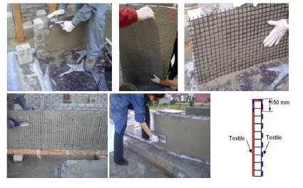
Figure 2-26 Practical application of TRM method (Source: Papanicolau, 2010)
79


