10 minute read
MEASURING THE VALUE OF LINER PROFILE GAUGES
from Quarry May 2019
by Prime Group
THE MERITS OF RUBBER TORSION SPRING MOTOR BASES IN SCREENS
The rubber torsion spring motor base has a lengthy history. Richard Sharp explains how it came to be devised and why it is such a critical part of extractive and broader industrial processes.
The first rubber torsion spring motor base for vibrating screens was developed in Australia in the late 1980s. It was based on the rubber torsion spring design credited to Hermann J Neidhart in the 1940s.
At that time, a rubber torsion spring unit was attached to a simple base plate. This was clamped to a predetermined angle, about that of the required torque for the functional specifications of the application.
On vibrating screens, when connecting the drive vee-belts directly to the screen excitors, it results in the pulley to pulley centres not being fixed. That is, the pulley centres change when the screen starts and stops (during resonance) as the screen body is mounted on steel coil springs for isolation purposes. This results in drive belt slippage in the start-up phase, and high vee-belt and pulley wear will happen.
Figure 1. On a Category A motor base, the electric motor is connected directly to the outer section of the rubber torsion spring.
CATEGORY A AND B MOTOR BASES A “Category A” motor base with a pre-loaded rubber torsion spring allowed the drive pulley to follow the action of the screen in resonance, maintain sufficient belt tension to avoid belt slippage and reduce the force transmitted to the supporting structure. This helped to extend vee-belt life, as well as the drive and driven pulley life, and resulted in lighter motor support structures, as the mass of screen was not being applied during resonance.
It should be noted that motor base designs fall into two distinct groups: • The “Category A” (Figure 1), which allows for the electric motor to be connected directly to the outer section of the rubber torsion spring. This allows for a resilient mounting and is ideal for applications such as vibrating screens or feeders when the vee-belts are connected directly to the excitor drive. The downside is the compression of the rubber cord under load allows misalignment of the drive and driven pulleys. To overcome this effect an alignment bearing is fitted to the drive side. This is referred to as a “dynamic application”. • The “Category B” (Figure 2), which has the electric motor connected to the inner section of the rubber torsion spring. In turn, this is Figure 2. On a Category B motor base, the electric motor is connected to the inner section of the rubber torsion spring.
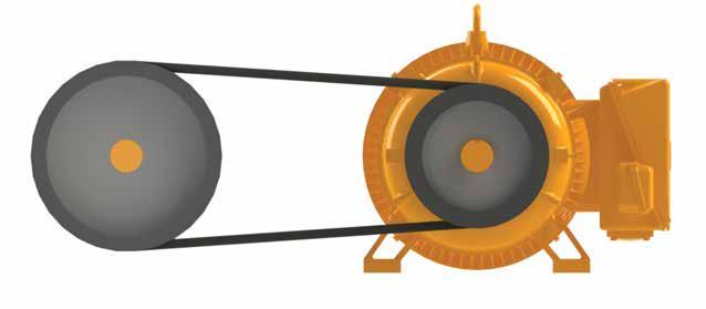
connected via bearings to the side plates of the motor base. The outer section of the spring is linked to a tensioning device for fitting and/ or changing drive belts and applying torque to maintain drive belt tension. This design is for static applications. That is where the drive and driven pulleys are fixed.
By the early 1990s, most vibrating screen drives rarely exceeded 30kW. However, once the market demanded larger motor bases for bigger screens and feeders with drives requiring motors 37kW and larger, it was obvious an improved mechanical adjustment was required.
Fully enclosed and lubricated mechanical tensioning devices were then developed. These have the benefit of being able to purge old grease and lubricants at regular intervals (eg twice a year) and remain failure-free. These designs have lasted 20 years.
DUAL SPRING MOTOR BASES Category A motor bases are without exception single spring (single pivot) in their design. However, Category B motor bases (Figure 3) can be both single and dual spring arrangements. The criteria are safety and mechanical design.
All large overhead motor base designs are dual spring and operate in a parallel configuration to lift the mass of the motor and tension the belts in a safe and efficient manner.
Figure 3. Category B motor bases can be both single and dual spring arrangements.

The design also minimises horizontal movement during this process. Horizontal (alongside) drives will also use dual springs, when the mass of the motor is unsafe to use a single spring (pivot). These are referred to as H-series (HA) drives.
The late 1990s saw greater emphasis on pump and crusher drives up to 630kW. Fitting, adjusting or changing out vee-belts and/or pulleys had major safety issues – particularly with larger overhead drives. These were all mounted on conventional jacking screws.
Overhead drives are more likely to present safety issues than those at the ground level. In most cases, reaching up above chest height is considered “part of the job”. Increasing the force required by adding a length of pipe is also considered “part of the job”. All of these add to personal risk and injury. Common accidents include strain injuries, falls and bruising.
In addition, mechanical problems due to design and/or corrosion should not be overlooked, eg an inability to make parallel the drive and driven shafts, to face drive and driven pulley, and to achieve and maintain the correct drive belt tension as per the belt manufacturer’s specifications.
COST SAVINGS In today’s market, labour is the single largest cost and companies strive for efficiencies and cost reductions. So, why do some end users ignore cost-effective designs that can reduce labour costs? Leverlink had a mining client that accepted as normal practice that it took a full eight hours, and four men plus a crane, to change out a set of vee-belts on a large pump drive. All of its pumps were conventionally mounted on jacking bolts.
Leverlink designed a Verti-lift (VL) motor base to fit the existing pump base frame, used the existing vee-belts, and recommended a new guard that could be removed by two men without the use of a crane. Windows were included in the guard at belt mid-span for checking belt tension or re-tensioning.
The initial design included details such as ensuring the drive and drive shafts were parallel and that the drive and driven pulleys were faced. Unless the motor was removed or perhaps new pulleys fitted they would remain so at each and every belt change-out.
The cost savings were undeniable. Two men in two hours now did what took four men and a crane eight hours. The payback period was well within the extractive producer’s financial model and it went on to install some 30 additional pump motor bases.
MOTOR BASE DESIGN LIFE The design life of Leverlink’s VL and HA series is 10 years. This estimate is based on the rubber cord service life used in the spring. Other factors that may be of influence include maintenance, environment and installation.
Motor bases can also be rebuilt and refurbished. This may extend their service life to 30 years or more. Many extractive sites recognise the cost benefits. •
HISTORIC SITE TO BECOME ‘WALKABLE’ SUBURB
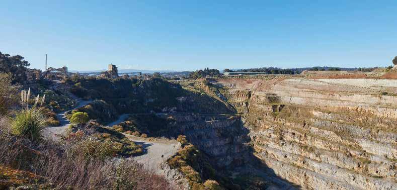
The former Cave Hill Quarry in Lilydale in Victoria’s Yarra Valley is being transformed into a new, vibrant suburb. Tim Robertson visited the site which is now into the second year of a 15-year development project.
On 9 May, 1901, the first Australian parliament was opened at the Royal Exhibition Building in Melbourne. This World Heritage-listed building had been constructed 20 years earlier; erected in just 18 months, it hosted the 1880 Melbourne International Exhibition, the first World Fair in the southern hemisphere.
Among other things, these fairs were catalysts for extraordinary feats of construction (eg Gustave Eiffel designed and built his tower as the entrance to the 1889 World Fair) and the Royal Exhibition Building has become one of the city’s most enduring and iconic landmarks. Built by David Mitchell, father of the world-renowned soprano Dame Nellie Melba, it embodied the hope and optimism of late 19th century Victoria, still basking in the plenty of the gold rush era. Mitchell, a Scot who immigrated to Australia in 1852, supplied the limestone from his Cave Hill Quarry in Lilydale in Victoria’s Yarra Valley. He also built several other notable Melbourne landmarks, including St Patrick’s Cathedral and the Scots Church in Collins Street. Even now, his limestone can be found in gardens across
36 Quarry May 2019 The 25ha, 120m pit, circa February 2018. About eight million cubic metres of material will fill the hole, on top of 105,000 tonnes of a 50–300mm rock for the drainage blanket.
the country in the form of the much beloved Lilydale toppings.
The quarry was one of the primary sources of limestone in Victoria from its establishment in 1878 to its closure in 2015. The site’s historical significance can still be seen in its physical fabric: Mitchell constructed an extensive battery of pot kilns in response to the limitations of intermittent burning technologies, which enabled roundthe-clock production. These heritage features – painted by one of Australia’s best known painters, Arthur Streeton, in 1935 – will be incorporated into the $2 billion residential and mixeduse development, which is expected to eventually house 8000 residents. The 162ha property was bought from Belgian multinational Sibelco in late 2016 as part of a joint venture with Bayport, Intrapac and Brencorp Properties. On a tour of the site, Daniel Petroni, development manager at Bayport, told Quarry that the old kilns would form the centrepiece of the future Heritage Quarter, home to farmers’ markets, paddock-to-plate-style eateries and space for family-friendly events.
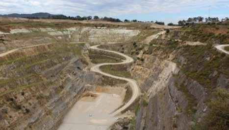
QUARRY REHABILITATION “There are plenty of examples where quarries of 30m to 40m have been successfully rehabilitated and developed on. This is the first quarry of its depth (100m plus) anywhere in the world that’s been rehabilitated with a plan to build on it,” Petroni told Quarry as we stood overlooking the 25ha pit. “Originally, the quarry was 120m deep.”
All the material that will be used to fill the pit will be sourced from within the site.
“Sibelco extracted around 13 million cubic metres and only around 25 per cent was removed from the site. The other nine million cubic metres was placed into overburden mounds,” Petroni said. “About eight million cubic metres will go back into the hole.”
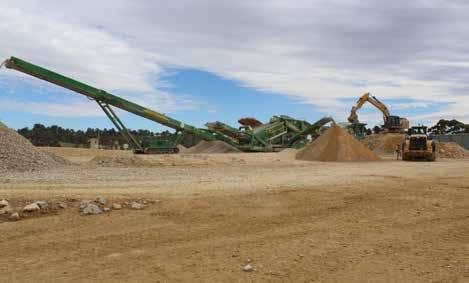
McCloskey equipment, supplied by MSC Group, is being used for all the on-site crushing and screening. The McCloskey J50 V2 jaw crusher, with its high jaw speed, ensures better reduction and faster processing of material through the crushing chamber. The McCloskey C44 V2 secondary cone crusher has a high material capacity and throughput.
The McCloskey R155 reclaimer has an open feed hopper and heavy-duty apron feeder, making it well suited to processing bulky material. The McCloskey S190 secondary screen features adjustable screenbox angles that allow adaptability to a wide range of material applications. Rounding out this mobile circuit is the agile and robust TS4065 tracked stockpiler. The tracks offer on-site mobility and the metre-wide belt ensures maximum capacity. It also integrates easily into the McCloskey range of crushers and screens. “To date, in terms of product, Bayport have produced a 50–300mm normal-style rock for the rock drainage blanket. They have done roughly 105,000 tonnes of that,” MSC Group’s Victorian sales manager Ian McCartney told Quarry.
“They’ve also produced 12,000 tonnes of a 50mm aggregate and 40,000 tonnes of a 40mm class 3 product. They’ve also processed topsoil and screened stockpiles of old material and other bits and pieces. And there remains a lot more work to be done.”
McCartney said that in the early stages of the project the McCloskey machines played an important role in cleaning up the site. “When it was a working quarry, all the overburden - the topsoil, the rock and the rubble - all that other stuff was pushed off to get the lime. So, all that stuff was around the quarry, which technically wasn’t waste, but it wasn’t the used product either. This overburden needed to be sorted and screened and crushed to make material out of,” McCartney said.
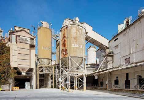
LONG-TERM PROJECT It is estimated that the quarry pit will take six years to fill, but it’s a 12- to 15-year development project for the group, Petroni said. The old kilns and silos will be restored, repurposed, and eventually incorporated into the Kinley development.
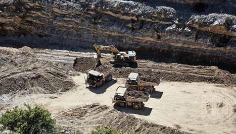
The Caterpillar 390F L hydraulic excavator is being used in conjunction with Cat 773 G trucks.
