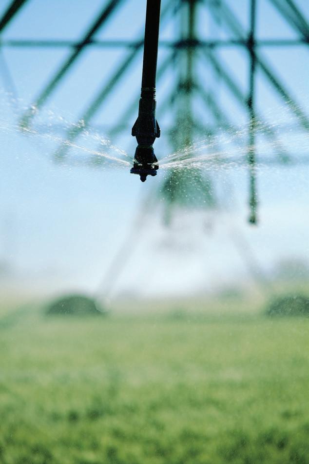
Future proofing irrigation with water recycling
Rewriting
the
code for HVAC pump selection
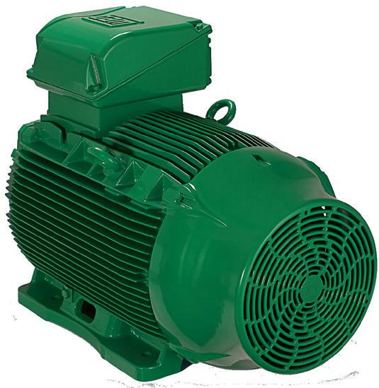
How to get the most out of your centrifugal motor


For 80 years Warman has been at the forefront of pump technology. The second generation WGR® is no exception. We’ve listened to what you need and innovated to create a pump that works harder than ever. The replaceable impeller and liners are manufactured using Linatex ® premium rubber, a proven performer in the sand and aggregate market. Plus the streamlined slurry flow path reduces recirculation and energy consumption, making this the best pump we’ve ever designed for sand and aggregate sites. Visit www.warman.weir to learn more.


Pump Industry Australia Incorporated PO Box 55, Stuarts Point
NSW 2441 Australia
Ph/Fax: (02) 6569 0160
pumpsaustralia@bigpond.com
PIA Executive Council 2018
Dave Alexander - President KSB Australia
John Inkster - Vice President Brown Brothers Engineers
Kevin Wilson - Treasurer/Secretary Executive Officer
Keith Sanders - Councillor Executive Officer - Marketing & Statistics Life Member
Alan Rowan - Councillor Executive Officer - Publications & Training Life Member
Ken Kugler Executive OfficerStandards Life Member
Ron Astall - Councillor Astech Technology
Mike Bauer - Councillor Dynapumps
Andrew Black - Councillor Envirotech Water
Malcolm Eyre -Councillor Franklin Electric
Ashley White - Councillor Davey Products
President’s welcome
We are well and truly into 2018. One moment I am enjoying camping at Byron Bay with the family over Christmas, and the next, Easter is here.
It is good to see your Pump Industry Australia team already working on technical meetings, seminars, installation commissioning courses and more. These take a lot of work, and I am sure you appreciate the effort the PIA committee put in to ‘make it happen’.
I had the opportunity to attend the first PIA Technical Meeting 2018 in February. This was held at Kelair Pumps.
Kelair’s Jeff Greely gave an update on Kelair and Brown Bros activities, and a tour through the workshop. Great to see the passion Jeff exudes for the work he does.
Paul Bannister and Alex Zeller from Energy Action Group, gave a very interesting presentation on changes to the NCC 2019, with considerable discussion on compliance, among attendees.
We appreciate both gentleman making the effort to travel up from Canberra to present and update PIA members.
Keith Sanders took the opportunity to update members on the changes to AS2417 – 2001 from a 9906-2012.
Keith focused on the key changes, and once again, another interesting presentation.
The PIA wishes to ensure there is industry awareness for the changes to the standard.
After the meeting, it was great to network with PIA members, having a drink and some food.
As I write this, it has been raining most of the night, with more rain on its way. This coming after several weeks of an intense heat wave through Southeast Queensland.
Listening to talk-back radio coming into work this morning, you realise how big of a country we live in.
The presenter had a lady ring in from Far North West Queensland, and talk about how bad the drought was where she lived and the impact it was having.
It’s the same predicament in parts of rural NSW where they need rain.
But there are parts of Southeast Queensland where it is forecast to receive more than 200mm of rainfall over the weekend.
For our farmers and anyone working in rain-dependent industries, I am sure it is a challenge.
I certainly know it is for my brothers who have farms in different locations (1600km apart) on the east coast of Australia.
But these weather challenges also give opportunities for the Australian pump industry, to get water from one place to another with the focus on doing it the most efficient way possible.
The PIA team has already had several conference calls and meetings this year. And we have a packed calendar ahead of us.
We are positive that you and the companies you work for will benefit directly from these PIA activities.
As such, I encourage you to regularly visit the PIA website, pumps.asn.au, to keep up with PIA events and happenings in your area.
Here’s to pumping, Dave Alexander
Many options, quick choice.


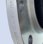

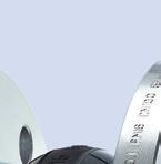
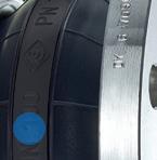


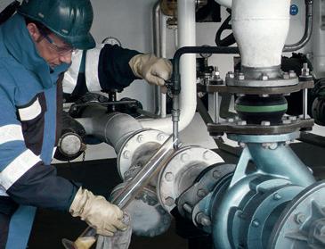


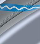
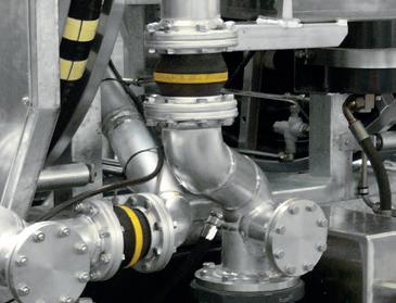
ERV-BR : Rubber Expansion Joint for abrasive Media


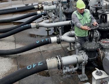
ELAFLEX PACIFIC, a daughter company of ELAFLEX Hamburg in Germany, is the supplier of the Elaflex product range: ZVA nozzles, rubber hoses, couplings and ERV expansion joints along with MannTek Dry Disconnect Couplings in the Pacific region, including Australia, New Zealand and the Pacific Islands.
The ELAFLEX ERV-BR, rubber expansion joint has been created specifically for abrasive media and is perfectly suited to the aggressive nature of sludge dewatering, mineral processing and the transfer of many types of slurries. Our online configurator is the perfect tool to get a fast and efficient overview of the product you require. Try it at
http://ervconfigurator.elaflex.com.au/






pumpindustry
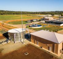
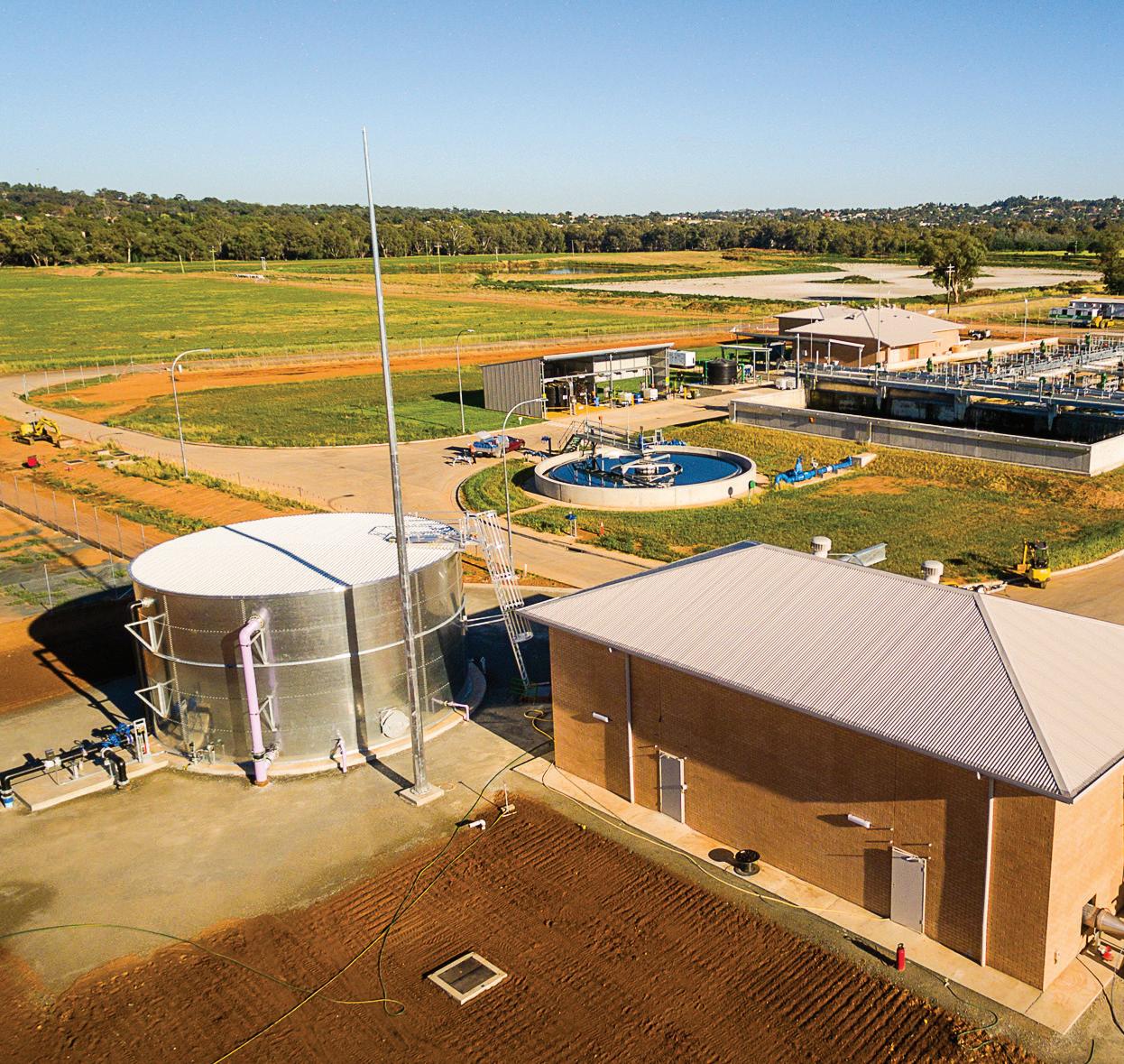
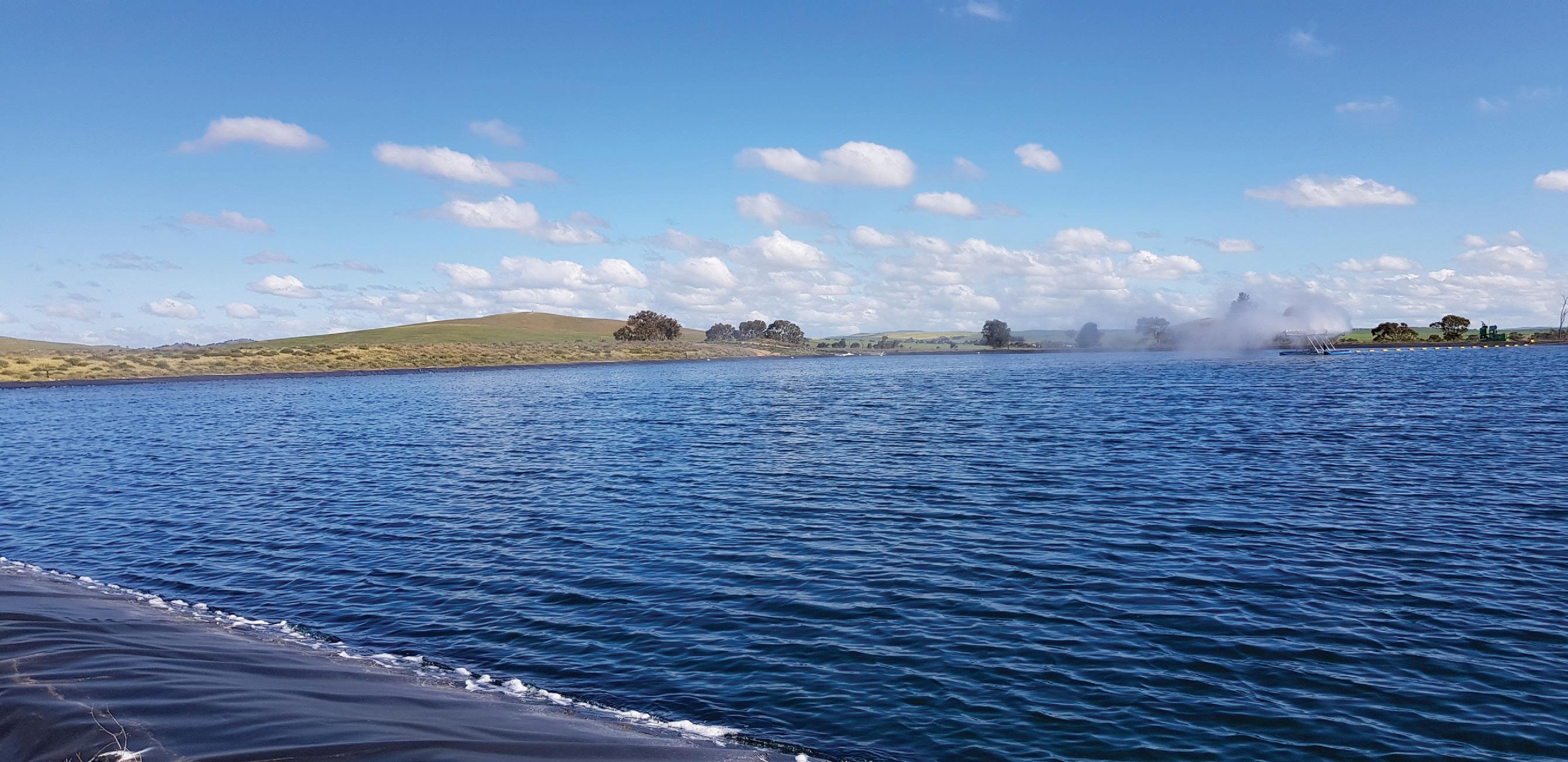
Cover image highlights the feature on water infrastructure upgrades being undertaken by Parkes Shire Council to future proof irrigation and water supply.
proofing irrigation with water recycling 4,358

Published by Monkey Media Enterprises
ABN: 36 426 734 954
PO Box 1763
Preston South VIC 3072
P: (03) 9988 4950
F: (03) 8456 6720
monkeymedia.com.au
info@monkeymedia.com.au
pumpindustry.com.au
magazine@pumpindustry.com.au
Publisher: Chris Bland
Editor: Lauren Cella
Senior Associate Editor: Jessica Dickers
Journalists: Elisa Iannunzio, Nicole Valicek, Kirsty Hutton
Marketing Director: Amanda Kennedy
Marketing Associate: Sam Penny
Marketing Consultants: Rima Munafo, Katie Chancellor, Helena Brace
Production and Customer Service:
Titian Bartlau
Senior Designer: Alejandro Molano
Designer: Jacqui Abela
ISSN: 2201-0270

PIA MEMBER NEWS
This magazine is published by Monkey Media in cooperation with the Pump Industry Australia Inc. (PIA). The views contained herein are not necessarily the views of either the publisher or the PIA. Neither the publisher nor the PIA takes responsibility for any claims made by advertisers. All communication should be directed to the publisher.
The publisher welcomes contributions to the magazine. All contributions must comply with the publisher’s editorial policy which follows. By providing content to the publisher, you authorise the publisher to reproduce that content either in its original form, or edited, or combined with other content in any of its publications and in any format at the publisher's discretion.



MOTORS AND DRIVES

Construction will soon begin on a new $52 million wastewater facility in Murray Bridge, South Australia. John Holland has been contracted to carry out the work which includes the construction of a new underground pipeline connecting the plant to the township, new pumping stations along the pipeline route, and the gradual decommissioning of the existing treatment plant adjacent to the Murray Bridge Marina.
The site is located around 10km south of the township, set back from Pfeiffer Road opposite the Brinkley Waste and Recycling Facility.
SA Water’s Senior Manager of Community Engagement, Matthew Bonnett, said a new treatment plant for the regional centre will provide numerous benefits for the local community, environment and SA Water.
“Since the existing treatment plant began operating in the 1970s, the population and needs of Murray Bridge residents and businesses have changed significantly. We are updating
our operations to align with community growth and activity,” Mr Bonnett said.
“The plant currently treats around 2.6 million litres of sewage a day, with 100 per cent of it recycled for irrigation use at a Department of Defence training area and a nearby pastoral property.
“The new plant will have a daily capacity of around 5.6 million litres to continue these operations and accommodate expected future growth in the area.
“Enhanced treatment processes and odour control facilities will also help minimise odour from the new plant.
“Moving the plant away from the River Murray floodplain and residential areas will improve its environmental performance by eliminating the current source of odour and the potential for discharge into the river during high flood events.”
Construction is expected to start in August 2018 with the facility expected to begin operating in early 2020.
MORE EFFICIENCY. SMART CONVEYING TECHNOLOGY.
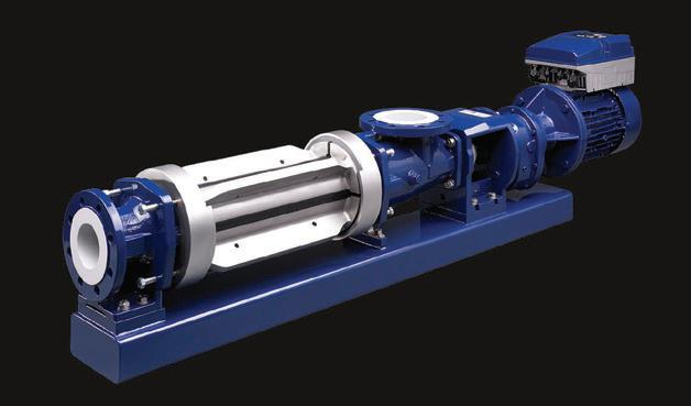
Pressure: up to 8 bar
Downtime: drastically reduced
Maintenance: simple and quick
Energy use: significantly reduced
Rotor and stator life:

Australia’s first seawater pumped hydro plant reaches next stage
The Australian Renewable Energy Agency (ARENA) has announced it will provide an additional $500,000 in funding to EnergyAustralia for the next stage of the 225MW Cultana seawater pumped hydro plant in South Australia.
The $8 million feasibility study will help advance the project to a final investment decision, and will involve the completion of project design including geotechnical investigations and equipment specifications, environmental impact studies and grid connection works.
ARENA previously provided $453,000 for the initial feasibility study which found the proposed Spencer Gulf plant was technically viable and could generate 225MW of electricity with 1770 MWh of storage equivalent using seawater as the storage medium.
If built, the Cultana facility would be the largest seawater pumped hydro facility ever constructed in the world, and the first in Australia.
A 30MW plant was built in Okinawa in Japan in 1999, and operated for 17 years.
The South Australian Government has also commited $500,000 to the feasibility study.
ARENA CEO, Ivor Frischknecht, said the next stage was an important step in building Australia’s first seawater pumped hydro plant.
“This pioneering project aims to build Australia’s first ever pumped hydro using seawater and could open up the potential for future seawater pumped hydro around Australia. Pumped hydro is the most common and mature form of energy storage which has been traditionally used in rivers, but seawater has the benefit of having no impact on rivers and no need to construct lower reservoirs,” Mr Frischknecht said.
Mark Collette, EnergyAustralia Executive – Energy, said Cultana would be a great achievement for pumped hydro in Australia.
“Pumped hydro is really a way of storing energy so it can be used when it’s needed, like a giant battery. Finding ways to store energy will be critical to Australia’s transition to cleaner energy so it’s great to have ARENA get behind the project with funding toward the next stage of its development.
“We’ve got a lot of work ahead of us this year with detailed design and engineering, community engagement, environmental assessments and approvals, but we’re excited about the potential for seawater pumped hydro to play an important role in Australia’s future energy mix.”

prosecution proceedings
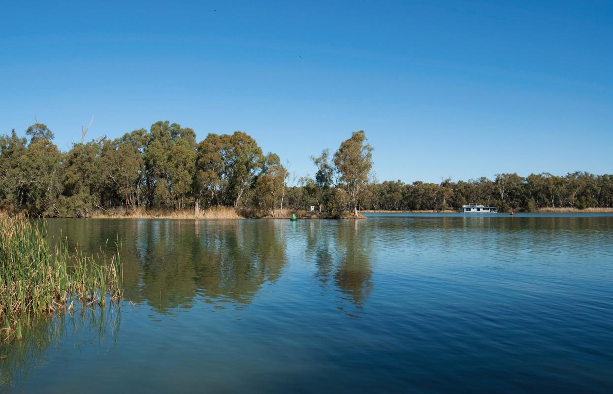
WaterNSW has commenced several prosecution proceedings against Barwon-Darling irrigators following extensive investigations.
These prosecutions are the result of comprehensive investigations into allegations of water management rule breaches in the Barwon-Darling unregulated water source in north western NSW.
The prosecutions include some cases concerning a property that has been the subject of media coverage, as well as another property that WaterNSW has investigated as part of its compliance activity.
In the Land and Environment Court action against Peter Harris and Jane Harris, WaterNSW alleges that the defendants took water when the flow conditions did not permit it, and breached licence and approval conditions. The maximum penalty for each of these offences is $247,500.
In the Land and Environment Court action against Anthony Barlow, Frederick Barlow and Margaret Barlow, WaterNSW alleges that the defendants were pumping during an embargo and pumping while metering equipment was not working. The
maximum penalty for each of these offences is $247,500.
In 2017 and 2018 WaterNSW carried out detailed investigations concerning activities in the Barwon-Darling region and an assessment of the factors relevant to whether it is appropriate to commence prosecution proceedings.
In determining whether to commence a prosecution for alleged illegal water activities, WaterNSW must have regard to the criminal standard of beyond reasonable doubt and it must act impartially, in the public interest and without influence from external pressures.
Completing the necessary investigations and determining the appropriate regulatory response within these parameters takes time.
As these matters are now before the court, further details will not be released.
WaterNSW is also completing investigations of other alleged illegal water activities in the Barwon-Darling and other water sources, and expects to provide further updates regarding enforcement action shortly.


cool with quality, affordable
Research, price, buy at: w w w.direc tautomation.com.au

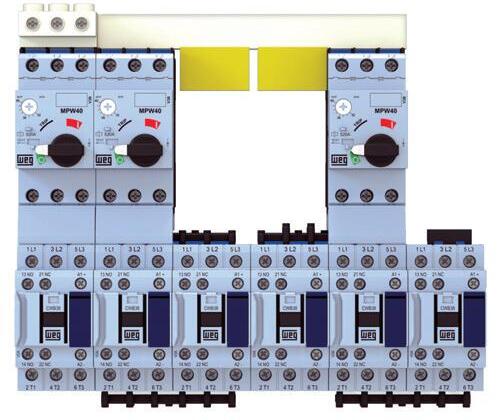
Contac tors - CWB Series
• Built-in 1NO + 1NC
Up to 80A / 37 kW (AC-3)
• Low Consumption DC Coils
• Wide range of accessories
•
• Type 1 / Type 2 coordination
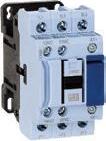
Our ever yday prices star t at $32.00* for a 9 amp Contac tor * (CWB9-11-30D25)
Motor Protec tion Circuit Breakers
Up to 100A / 55kW
• Adjustable Thermal Protection
• Fixed Magnetic Protection
• 13 x Iu Shor t-Circuit Release
•
• Type 1 / Type 2 coordination

Our ever yday prices star t at $49.00* for a 4-6.3 amp Breaker *(MPW18-3-D063)
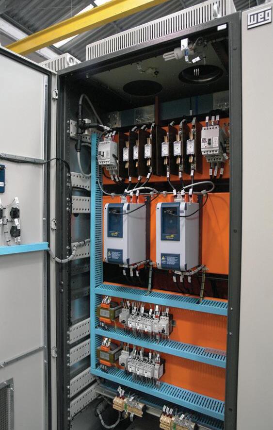
For over 20 years we’ve been saving our customers time and money on industrial automation produc ts including PLCs and HMIs, pneumatics, sensors, VS drives and switchgear. We have a huge inventor y that is constantly growing in order to provide you with the quality components you need to keep your projec ts moving. We have also invested heavily in new infrastruc ture that will allow us to continue offering the ser vice and suppor t you deser ve So don’t put that projec t of any longer...buy direc t today and save with Direc tAutomation.
Contract awarded for sewer pump station in Victoria
The contract to complete detailed engineering designs for Gippsland Water’s new outfall sewer pump station near the Port of Sale in Victoria has been awarded.
WSP was awarded the contract and design work has started.
Work is also underway at the site with demolition of a derelict building completed to make way for the new piece of infrastructure, which will be built on Foster Street, opposite the Police Station.
Gippsland Water’s General Manager Customer and Community, Paul Clark, said the new pump station will be a major improvement to Sale’s sewer network.
“This project will cater for population growth in Sale, Wurruk, and Fulham for the next 50 years. It will also allow us to demolish the existing outfall sewer pump station on Park Street,” Mr Clark said.

“The new pump station will feature industry-standard odour mitigation technology and reduce the likelihood of spills into Flooding Creek.
“We’re proud to support growth and

liveability in our region by investing in projects that improve the capacity of our network and protect the environment.”
Construction is expected to be complete by April 2021.




SA Water has awarded the contract to upgrade the sewer network in Adelaide’s north-west to support future growth in the area and improve odour management.
Fulton Hogan has been contracted to undertake the work, which is scheduled to begin in April 2018.
The $12 million project involves a refurbishment of the Largs North Wastewater Pump Station and the installation of a new 4.5km sewer main from the Largs North site to the Ethelton Wastewater Pump Station.
“The existing facilities, while currently
CONTRACT AWARDED FOR SEWER UPGRADE IN ADELAIDE
fit for purpose, won’t be able to meet an expected increase in demand on our sewer network brought on by growing urban developments such as Newport Quays and new industry in the northern parts of the Le Fevre Peninsula,” SA Water’s General Manager of Asset Operations and Delivery, Mark Gobbie said.
“Our Largs North Wastewater Pump Station currently has the capacity to transport around 75 litres of sewage per second. The upgrade will allow this to increase by around 40 per cent to 106 litres per second.
“By upgrading the local network, we are reducing the likelihood of odour and overflow issues that new connections can cause, through improving the network’s reliability and environmental performance. We are ensuring we continue to support good public health outcomes through appropriate sewage management.”
The new sewer pipeline is being installed using a construction method known as directional boring, which requires less excavation and therefore results in a reduced impact on nearby residents and road users.









Better water for regional towns in Tasmania
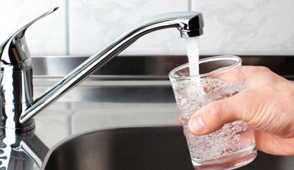
The North Eastern Tasmanian towns of Gladstone and Herrick have received new custombuilt modular water treatment plants, delivered from the factory floor in Launceston.
The plants are part of TasWater’s multi-million dollar project to remove all public health alerts on drinking water systems in regional towns of Tasmania.
Gladstone will start receiving treated drinking water in the coming weeks with nearby Herrick soon to follow.
TasWater will undertake a program of testing to ensure the treated water from the new plants meets Australian
Drinking Water Guidelines, before the Department of Health and Human Services can lift the Boil Water Alerts that currently affect those towns.
TasWater contractor TRILITY, with its partner Hydramet, have completed the construction of three of the seven plants to come out of the factory.
The plants were crane lifted onto low loader trucks in the Launceston factory before being escorted to the sites.
An 85 tonne crane on the Gladstone site lifted the new water treatment plant in late February 2018, with plumbing and installation taking place before it can begin producing water.
Construction continues in the factory on the water treatment plants for Cornwall, Mathinna, Rossarden and Bronte Park which will be delivered in the coming months.
TasWater CEO, Mike Brewster, is pleased the first three plants will have been delivered to site by the beginning of March 2018.
“Wayatinah, Gladstone and Herrick have now received water treatment plants made in the factory in Launceston with the rest of the plants to be rolled out in the coming months,” Mr Brewster said.
Production continues in a Stornoway facility in Glenorchy on the water treatment plants set to supply Fentonbury/Westerway, Maydena and National Park.
New water infrastructure, including extended mains pipelines, is also under construction in the regional towns statewide.
“The plants manufactured in the Prospect facility as well as the other infrastructure in the towns, once completed, will treat the drinking supply for over 600 TasWater customers,” Mr Brewster said.
“We are on track to delivering this safe, treated drinking water to the tap in the regional towns by the end of August this year.”


The ASM C Series sump pump is built tough for reliable uninterrupted operation in the most demanding conditions.
What makes the ‘C’ Series so robust is what it doesn’t have; a submerged motor, bearings or mechanical seals, the primary causes of failure in conventional sump pumps. The heavy duty shaft and bearing assembly is above the mounting plate, clear of the sump environment. This feature allows the pump to run dry indefinitely without damage, pump extreme temperature liquids and have a high tolerance to abrasive fluids.
Additional to these benefits is the fact that the pump is always
primed and ready to work. The C Series is available with material and design options for clean liquids, solids handling, chemicals and extreme temperatures.
This is the pump you need when you want peace of mind. For more information contact ASM Pumps on (03) 9793 7577 or visit asmpumps.com.au

Works start on stage two of Gippsland water project
Work has started on the second stage of Gippsland Water’s new pipeline and pump station.
The $15 million Moe to Warragul interconnector will allow the transfer of up to eight million litres of water per day between the two previously unconnected water grids.
The second stage of the project involves construction of a pipeline from Darnum to the Warragul South basin on Korumburra-Warragul Road, along with new booster pumps at Darnum and a new pump station at Trafalgar West.
Gippsland Water currently takes water from the Tarago Reservoir to supply Warragul and Drouin, but entitlements are limited as the reservoir also supplies Westernport and the Mornington Peninsula.
The interconnector will allow the transfer of water in either direction, offering improved operational security and making the region more resilient to changes in supply and demand, such as climate change and population growth.
Gippsland Water’s General Manager Customer and Community, Paul Clark, said that the new pipe is a key piece of infrastructure.
“We’re proud to support the economy and liveability of our region by investing in the water grid. Ultimately, we’re ensuring that Gippslanders are able to benefit from our valuable water resources, and enabling water to be accessed from a wider range of sources,” Mr Clark said.
The first stage of the project, a pipe between Yarragon and Darnum, was completed in 2012.
Construction of stage two is expected to be complete by mid-2018, and the pipe is expected to be operational by 2019.
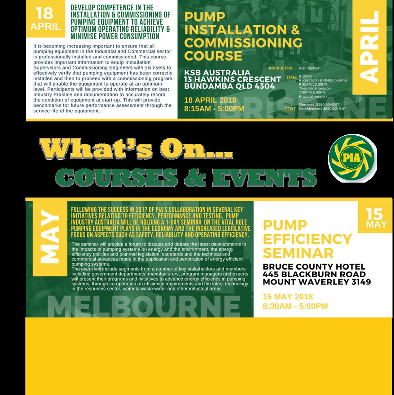

RELIABLE. EFFICIENT. KSB AUSTRALIA’S NEW GENERATION OF WASTEWATER PUMPS
The new generation of wastewater pumps: impellers capable of handling long fibres and solids, and high-efficiency KSB motors – the Amarex KRT and Sewatec type series offer even better overall efficiency.
Energy-efficient wastewater pumps and motors for optimum efficiencies
Municipal, domestic or industrial wastewater: the submersible motor pumps of the Amarex KRT type series are the perfect match for all wastewater transport requirements.
Not least because KSB’s wastewater pumps combined with high-efficiency motors enable significant energy savings.
Reliable and efficient: the new non-clogging impeller
Maximum efficiency and minimum clogging risk for KSB wastewater pumps are provided by the F-max free-flow impeller. With the asymmetric arrangement of its vanes, F-max offers a large, free passage that allows solids of different sizes to pass without difficulty.
The slightly convex profile of the hub in the middle of the impeller reliably prevents all risk of clogging
from long fibrous materials such as flushable wipes.
The F-max free-flow impeller is available for the submersible wastewater pumps in the Amarex KRT series and the dry-installed wastewater pumps from KSB’s Sewatec series.
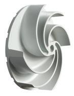
The F-max vortex impeller by KSB Australia
Energy-efficient motors for optimum efficiency
The combination of KSB wastewater pumps with high-efficiency motors enables considerable energy savings. The economical motors are integrated
in the pumpsets as standard. The pumpsets can be supplied with or without explosion protection.
The dry-installed pumps of the Sewatec type series are fitted with the variable-speed, magnetless KSB SuPremE® IE4 motor. The efficient pump set, consisting of a wastewater pump and motor, promises maximum savings from low energy and maintenance costs, optimum operating reliability and constant performance data.
Customised pumps for every requirement
Team with specifically adapted impellers and energy-efficient motors. KSB offers a wide range of installation types as well as a large choice of materials for wastewater pumps. KSB tailors the best solution for each wastewater application – for optimum efficiency and operating reliability.
REMOTE WITNESS TESTING: A FIRST BY KSB
When purchasing large pumps, hydraulic acceptance tests and a final inspection are an essential proof of compliance with the guaranteed values.
In the past, customers had to travel to the test facility to witness their purchased pump being tested. As testing usually takes place at the KSB manufacturing plant overseas, this is a time-consuming and costly trip to make from Australia.
Online acceptance testing is KSB Australia’s answer, developed as a process enabling reliable and standardcompliant pump acceptance testing. The tests conducted are transmitted live via a secure internet connection. In an online meeting between pump manufacturer and customer, the customer can see the live camera view of the pump in the test facility, as well as the characteristic curve measurement during testing.
In addition to pressure and flow data, the test software records all further performance data required for a measurement to inspection/testing standard DIN EN ISO 9906, enabling
the derivation and assessment of the pump’s efficiency. Measurements can also include the sound level and vibrations. Prior to the acceptance test, KSB provides the customer’s test engineer with organisation information, order data sheets and a precise description of the acceptance testing.
This comprises details on the measuring instruments used, including the corresponding calibration certificates. After the acceptance test, KSB emails the test engineer the certificates to be signed. This tried and tested process is implemented in compliance with the acceptance test standards.
Online acceptance testing is available from KSB’s Halle site, specialised in water and wastewater pumps, as well as at some of
the pump manufacturer’s other sites. The test facilities can accommodate pumpsets with a drive rating of up to 10MW and a flow rate of up to 21,000 m3/h.
String tests with the customer’s original motors, transformers and frequency inverters can also be performed.
At KSB Australia’s stand at OzWater, a 360-degree presentation will give interested parties a good impression of the test facilities for online acceptance testing at the KSB site in Halle, Germany.

SAVING A FORTUNE FORTUNATELY DOESN‘T COST ONE.
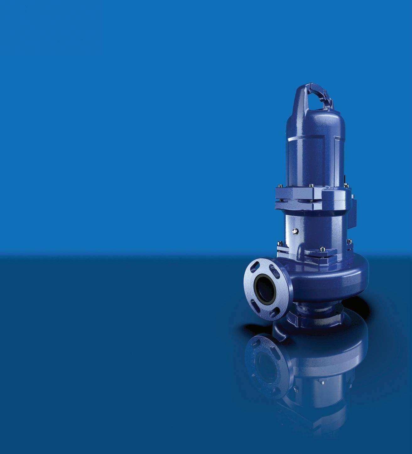
Efficient, reliable and fail-safe pumps pay off in the long run.
www.ksb.com.au
New range of EN733 pumps: WORLD LEADING PERFORMANCE
As a major manufacturer of industrial pumps to JIS and API610 standards, Ebara Corporation has embarked on a globalisation of its range of pumps for the world market. This includes the introduction of a range of industrial pumps to European EN733 standards and a new range of vertical multistage pumps.
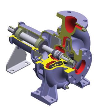
Ebara Corporation (Japan) has recently released its new global range of EN733 standard end suction centrifugal pumps.
Utilising the most advanced hydraulic computer design software available, Ebara engineers in Japan have been able to improve and increase the pump efficiencies of the new GS range above most other available pumps of similar design and standard on the global market.
The new Ebara GS range of EN733 standard pumps are manufactured in component form at Ebara Corporation Japan owned and managed factories in the Asia Pacific region with final assembly of market range models undertaken by skilled tradesmen at Ebara Pumps Australia’s Melbourne facility.
A 16 bar rated pump – the new GS –will be available in both long coupled and close coupled versions (GSD) and will be available for release in Australia in the second half of 2018.
About Ebara Corporation
Ebara Corporation was founded in Japan in 1912 as a manufacturer of pumps. Today, as a group, it consists of more than 70 companies in six continents with a workforce of more than 11,000 people and with company owned and Japanese managed factories in eight countries covering four continents.
The huge scale of production and distribution is matched by a constant commitment to research, development and design of new products and the
modern technologies for manufacturing them. Ebara products have gained a worldwide reputation for their technology and quality.
Contact your local Ebara dealer or Ebara Pumps Australia for more information.
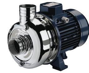
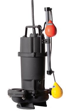
Two of the more popular models that are stocked in Australia are both solids handling pumps. For more details contact us at Ebara Pumps Australia or visit our website.
Stamped stainless steel pumps with open impeller
Maximum 19mm passage size
MODEL DWO MODEL DVS
50mm discharge
1.1 to 1.5kW - 1 phase
1.1 to 3.0kW - 3 phase
Cast iron submersible pumps with semi vortex impeller 32 to 56mm passage size (Depending on model)
50 and 80mm discharge
0.4 to 0.75kW - 1 phase
0.75 to 3.7kW - 3 phase
Manual or automatic
New hydraulic design - World leading performance
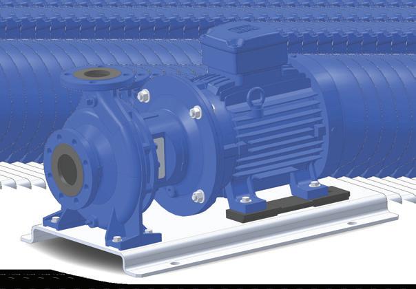
Combining over 100 years of experience with the latest computer aided design, EBARA has developed the new GS series of pumps that offer world leading performance and efficiencies.
End suction single stage centrifugal pumps
Pumps to EN733 dimensions
16 Bar rated. PN16 flanges (24 Bar hydrostatic test pressure)
High efficiencies. MEI ³0.6 (Minimum Efficiency Index)
Mechanical seals to EN12756
Protectors to ISO13852
O’ Ring seal for casing
Cast iron components ED painted (Electro deposition painting)
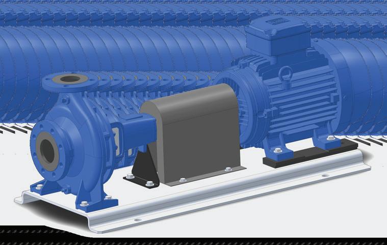
GS range - 41 pump sizes from 32-125 to 200-500
GSD motor pump versions available from 1.1 kW up to 75 kW (4 pole) and 110 kW (2 pole)
Performance, robustness and reliability: PMXT ENDURANCE
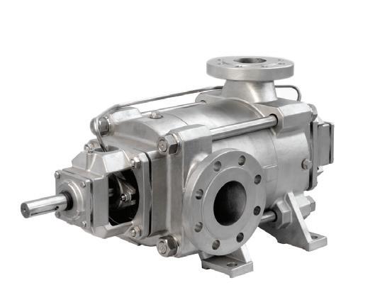
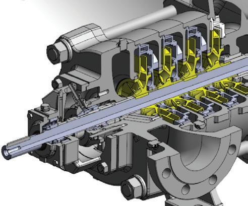
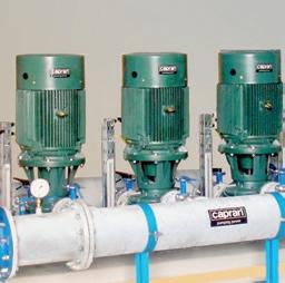
Caprari has launched the new range of high pressure multistage surface horizontal pump series PMXT ENDURANCE completely made of precision-cast stainless steel.
Very thick components, the choice of high performing materials, the innovative technical solutions and the smooth surface of hydraulic profiles make the PMXT ENDURANCE pumps unique on the market for their performance, robustness and reliability.
The pumps are:
• Able to reach performance values up to 100 bar pressure with top-level efficiency ratings
• Made of AISI 316 stainless steel precision-castings suitable for harsh operating conditions
Also available are full duplex and full super duplex versions, which are suitable for extreme industrial applications (i.e. reverse osmosis, seawater fire prevention, seawater injection, etc).
The balanced mechanical seals have been specifically selected for industrial applications.
The Caprari axial thrust compensation system is present on the whole range, minimising the loads that persist on the bearings of the machine, giving the product a long life.
The wear rings are replaceable and made in duplex with anti-seizing properties and self-lubricated. At the same time, this solution makes it possible to minimise the gap between the impeller and the wear ring, improving hydraulic efficiency and avoiding seizure problems.
Optional PT100 probes are useful for monitoring bearing temperatures. Together with the vibration probes, which are also optional, it is easy to monitor the wear level of the bearings, thus preventing costly downtime.
Caprari surface groups made with high-pressure multistage pumps are a benchmark for the market. The product's wide range makes it possible to always find the best solution for the customer's duty point at the highest efficiency level.
With the ENDURANCE series in stainless steel and duplex, Caprari satisfies the most demanding industrial market applications.
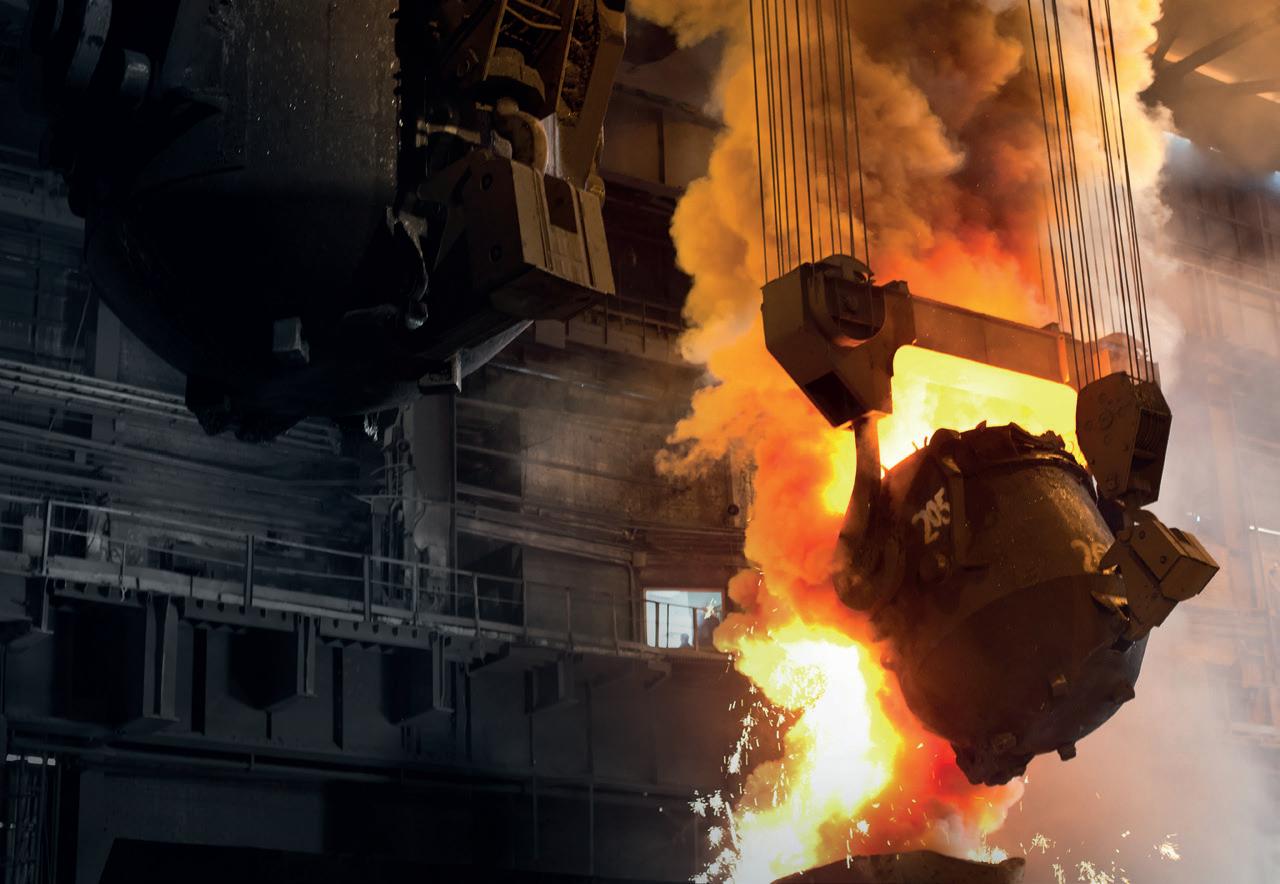
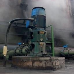
YOUR RELIABLE PARTNER IN INDUSTRIAL APPLICATIONS EXPERIENCE SINCE 1945
Designing the future with highly appreciated and advanced solutions for Industrial Applications
Pumps and electric pumps able to raise primary process water and waste water.

ENERGY | METAL INDUSTRY | PAPER INDUSTRY | FOOD & BEVERAGE
www.caprari.com |

Each mobile pump is unique
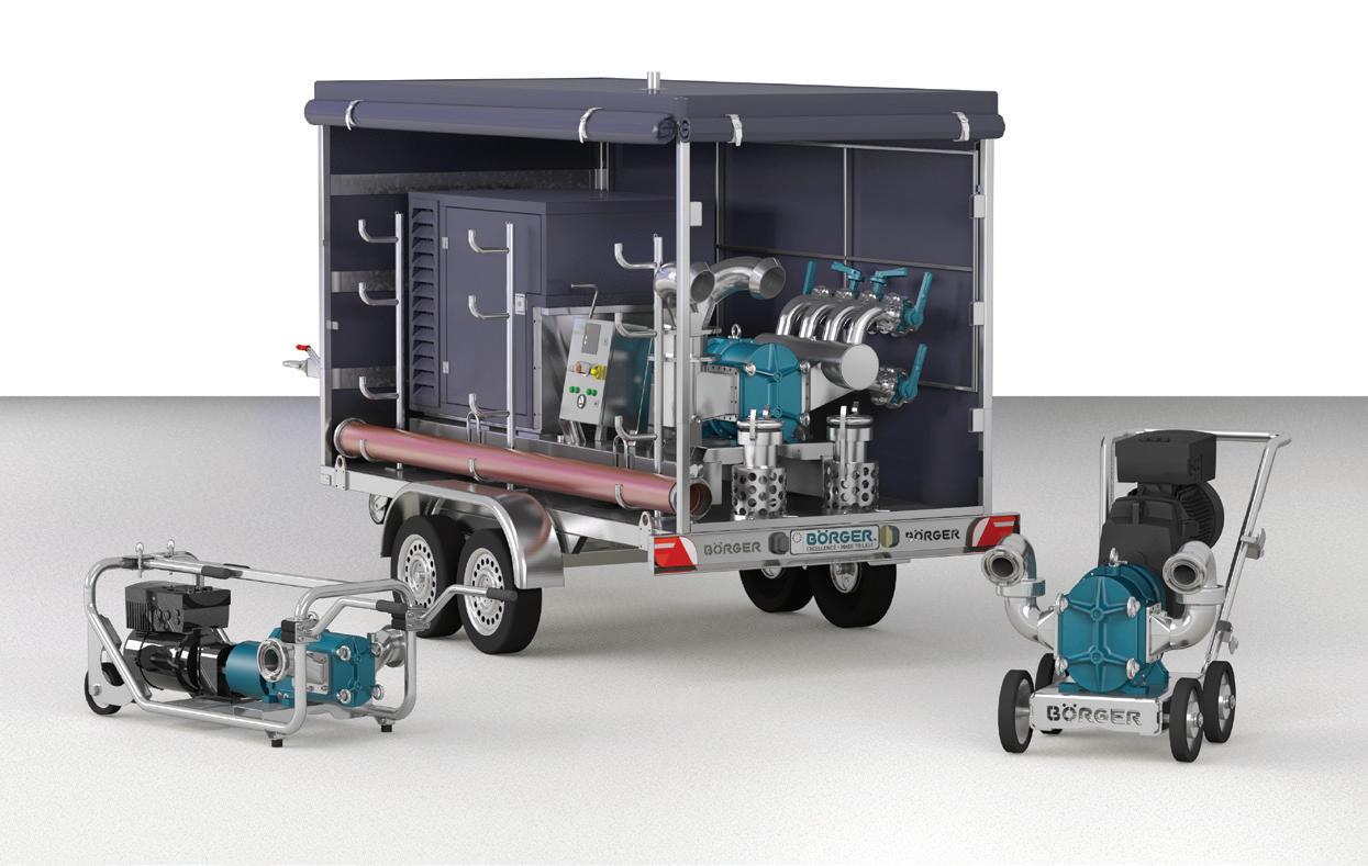
The rotary lobe pumps from Börger, a pump manufacturer from Germany, are built in line with the individual requirements of the customer. The demand for Börger mobile pumps has increased in recent years.
Börger GmbH from Germany has manufactured rotary lobe pumps for more than 30 years. The self-priming, valveless positive displacement pumps are used in the environmental and municipal technology sectors, and in almost all industrial sectors. The solids-resistant Börger pumps are available in the BLUEline and ONIXline series. The pumps convey highly viscous, chemically aggressive media or media containing solids without any effort.
The correct pump size for every single application is selected from a portfolio of 25 pump sizes with flow rates of 1 to 1500 m³/h. All pump components are selected individually according to the requirements of the pumped medium and the customer. Rotors in different geometric
designs and made of a wide range of different materials; pump casings made of gray cast iron, steel casting, stainless steel or Hastelloy; and different sealing systems only give an idea of the wide variety of Börger rotary lobe pumps.
Börger mobile pumps have the same individual character. The demand for mobile pump units has increased in recent years. There are hardly any limits when installing a mobile pump. Whether as a pump on a trailer, a portable pump or as a hand cart pump which can be used flexibly. The mobile units are supplied from a single source. Börger produces the chassis, the pump technology and the control technology themselves. This way, we will be able to provide a customised solution to our customers’ requirements.
MOST EFFICIENT WAY OF PUMPING


POWERFUL.
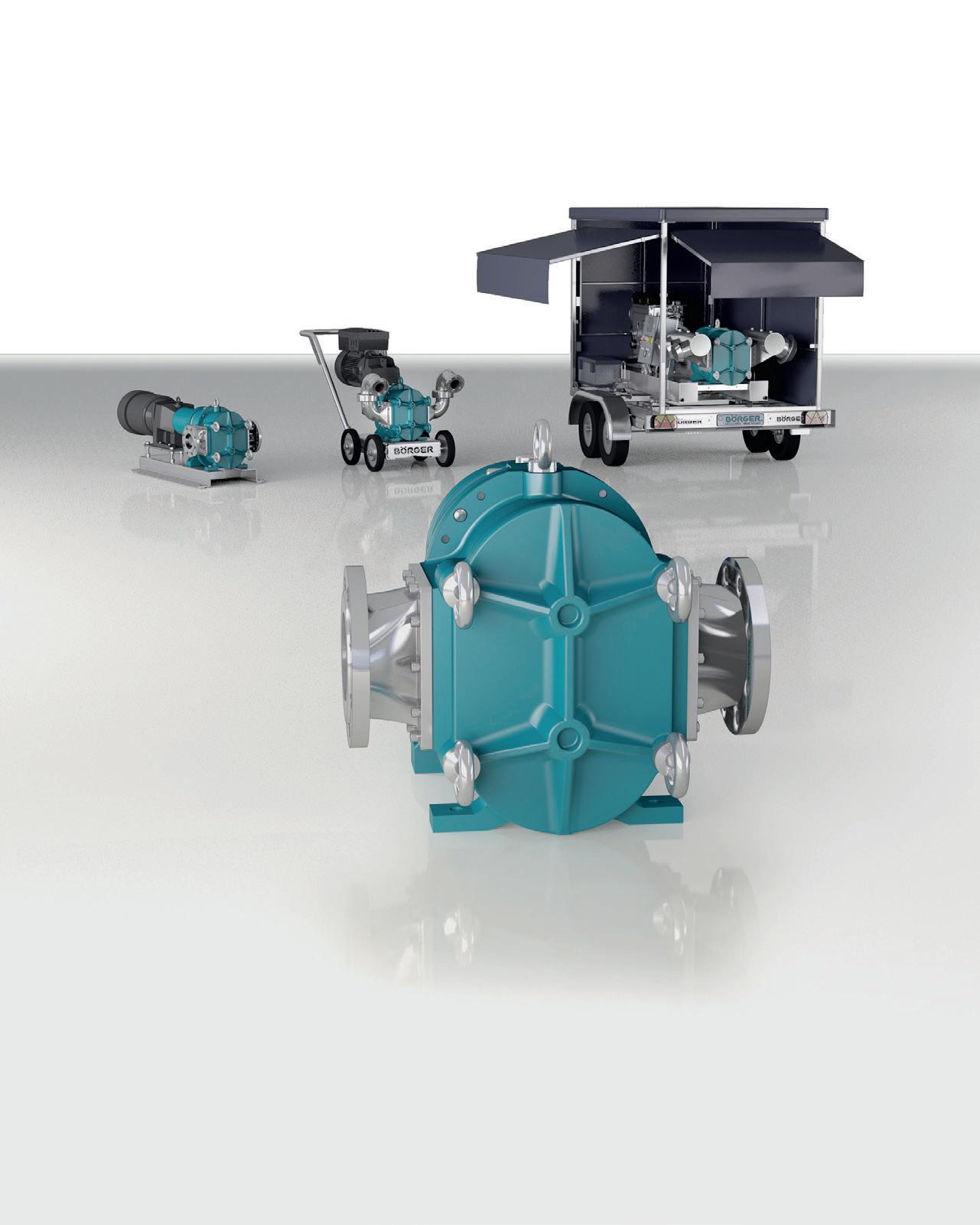
Börger configures and builds each rotary lobe pump in line with your requirements. The solidsresistant pumps ensure the best efficiency even with pressures of up to 16 bar. The correct pump size for every single application is selected from a portfolio of 25 pump sizes with flow rates of 1 to 1,500 m³/h. Börger rotary lobe pumps are especially suitable for mobile use due to their
compact design. The mobile units are supplied from a single source. Börger produces the chassis, the pump technology and the control technology themselves. This way, your individual requirements and wishes can be considered.

MONITORING VIBRATIONS with new powerful compact sensor
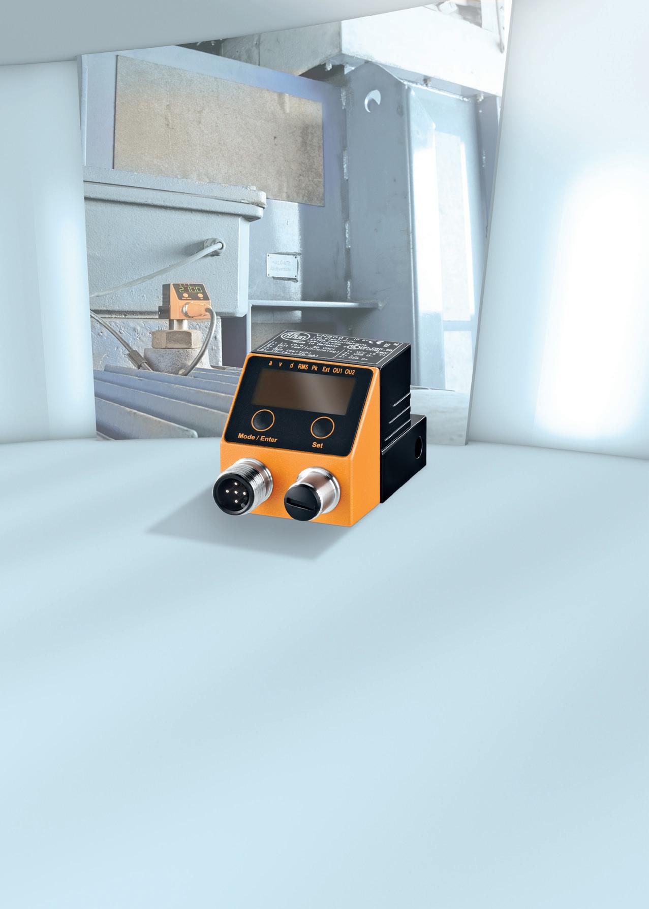
ifm has now added another intelligent vibration monitoring sensor to our already comprehensive range. This sensor has been developed to protect machinery to a high standard without spending a huge sum of money and still affording a great deal of protection.
This unit looks almost identical to its brother the pre-existing VNB001 with its local displays, but this is where the resemblance ends.
This small unassuming unit now has a huge array of functions available in its portfolio.
The VNB211 is a standalone monitor that has the following algorithms: V-RMS to ISO10816 or it can be set to peak if desired.
This generation also has A-RMS (Acceleration RMS) which sensors of this size normally do not have. This acceleration algorithm is normally used for bearing damage detection and whilst it is not band specific, good protection can still be afforded by its use.
In addition to these desirable functions, a small ‘Y’ cable can be added to the M12 port so an external 4-20mA device - e.g. a temperature transmitter, which was also possible in the VNB001 - can be included, or excitingly, another accelerometer (VNA001) which turns the unit into quite a powerful twin accelerometer system. This means that it is possible to monitor DE and NDE ends of a large fan for example. Once programmed, either by the on-board push buttons or by the software, the sensor will run totally autonomously, giving an analogue output or set-points as required.
It doesn’t stop there either. The VES004 programming software enables full setup of the above algorithms with full control of set-points, time delays and histories. The history function alone is a very powerful tool. Log rate is as low as one second intervals for around 90 days. The default is set as five
minutes and thus will log for three years without overwriting. This is perfect for monitoring trends over long periods of time.
Such is the power of this system that Spectra and Time Waveform can also be monitored when connected to the VES004 software. These files can be trended and saved as desired then played back at any time for analysis or comparison. No matter what you have connected to the VNB211, whether it be an accelerometer, pressure or temperature transmitter it can all be logged internally and then saved to a file when the programming cable is connected.


Agitator pumps for all applications
Australian Pump Industries, Tsurumi’s Australian distributors, is proactive in developing applications for slurry pumps. Tsurumi is now regarded as a leading submersible slurry pump manufacturer, with a wide range of pumps suitable for handling everything from sandy, salty water, to heavy duty slurry found in the quarry, mining or the concrete industry.
Tsurumi, claimed to be the biggest manufacturer of electro submersible drainage pumps in the world, developed dewatering pumps during the land reclamation program of the 50’s and 60’s in Japan. Used by the piling and concrete industry, products were designed for these aggressive and abrasive applications.
Today the company is highly specialised, making slurry pumps from 2-pole all the way to 6-pole, capable of handling sandy liquids in quarries and concrete plants.
The secret of their success is the design of high chrome, cast iron agitators that ensure the smooth suction of the settled matter. This same philosophy is used in single and 3-phase pumps alike, providing the ability to move solids in suspension that conventional pumps can’t handle.
The ultimate extension of the product range is 4 and 6-pole pumps with huge flows, capable of pumping thick slurry. Tsurumi’s 4-pole GSZ Series will handle flows of up to 18,000 LPM, and heads of up to 54m.
The impeller, agitator and suction plate are made of high chrome cast iron to resist abrasion. Even if the impeller and suction plate wear down to the point of diminishing pump performance, the plate can be easily replaced or its gap from the impeller adjusted, giving users an easy, inexpensive means of extending use.
Tsurumi’s GSD series, a new range of heavy duty, high powered agitator pumps, feature horsepower ratings of up to 75kW. They feature high heads and volumes and are set to change the way the international market thinks about mine, quarry and heavy mineral movement.
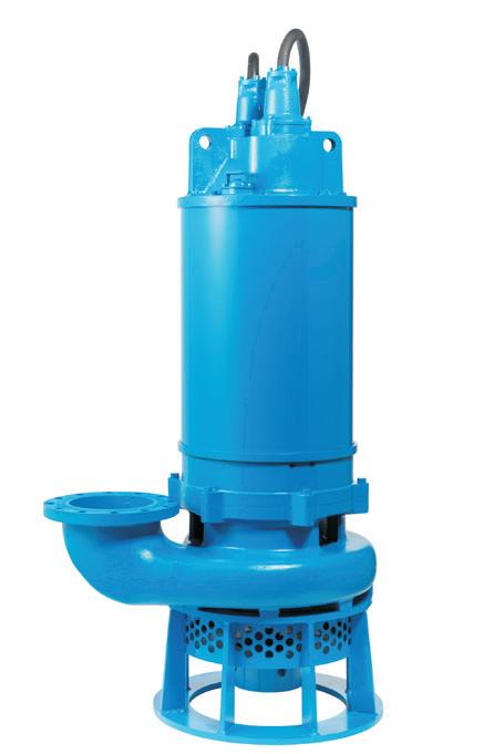
Big GSZ slurry pumps have an inbuilt agitator impeller to make sure the liquid is moving before it comes into the main pump chamber. That’s Tsurumi’s advantage.

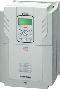


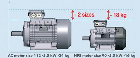
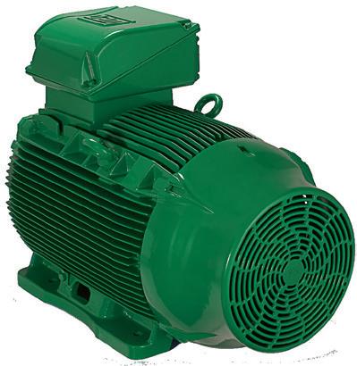
The High Performance (HP) range from Lafert is a generation of PM (Permanent Magnet) Synchronous Motors, achieving IE4 and IE5 Super Premium Efficiency level, that offer improved electrical efficiency at stable & reduced production costs without applying rare earth magnets.
This uniquely engineered product combines the electrical design of Brushless Servomotors with the mechanical design of AC Induction Motors. The result is a compact motor primarily targeted toward HVAC applications in pumps, fans, compressors, and blowers, where there is emphasis on reducing the operating cost and weight and size of the motors.
The complete range 0.37 kW to 30 kW are supplied as stand-alone motors (HPS) to be controlled by a separate drive or as motor/drive integrated units (HPI), specifically designed for their energy saving potential.
RECHARGING PERTH’S
The south west corner of Western Australia continues to dry, and hotter summers combined with lower rainfall have led to Water Corporation seeking new ways to secure climate-resilient water sources. To help secure more water, the utility has embarked on an expansion of its $262 million Groundwater Replenishment Scheme — the first full-scale scheme in Australia — which will see 28 billion litres of water per year pumped back into Perth’s aquifers for reuse.

PERTH’S GROUNDWATER
The process of groundwater replenishment is an innovative concept that involves treated wastewater being further treated so that it’s good enough to drink, before being recharged into groundwater supplies. This water is then stored or ‘banked’ in the aquifers, and taken out later for further treatment and supplied to a drinking water system.
As the process doesn’t rely on rainfall and has the potential to recycle large volumes of water, it is sustainable and drought-proof.
Planning on water forever
For this reason, Water Corporation has prioritised groundwater replenishment in its Water Forever plan — a long-term plan to further secure water supplies in response to climate change and an increasing population.
The Water Forever plan is based on a three-pronged approach, which includes working with the community to reduce water use, increasing the amount of water recycled and developing new water sources.
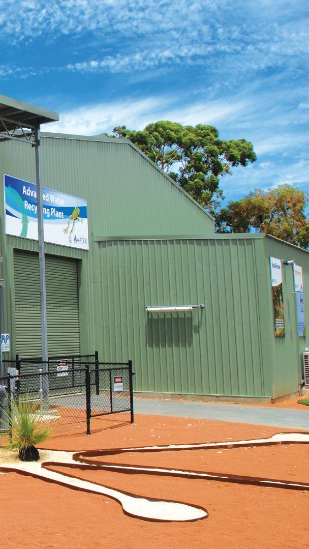
A Water Corporation spokesperson said the Groundwater Replenishment Scheme, taking place at the Beenyup Advanced Water Recycling Plant in Craigie, ticks two of these boxes as it increases water recycling and is developing a new source.
By 2060, groundwater replenishment could provide up to 20 per cent of Perth’s water supply.
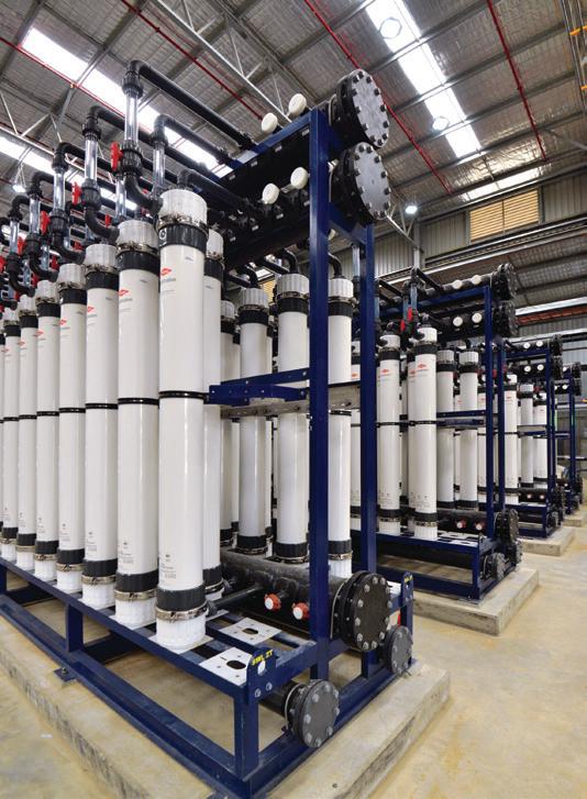
For the water to be recycled for reuse, wastewater is first rigorously treated at the Beenyup Wastewater Treatment Plant. It then undergoes further treatment at the onsite Advanced Water Recycling Plant where all trace levels of microorganisms and chemicals are removed so that it meets drinking water standards.
To achieve this, it is processed through three water treatment methods:
1. Ultrafiltration filters out suspended materials that are larger than 0.1 of a micron
2. Reverse osmosis removes any remaining dissolved materials by passing the water through tightly wound membranes
3. Ultraviolet light is used to destroy any trace levels of microorganisms that may remain
Once water has passed through the three stages, it is of drinking water quality and is recharged into the aquifer where it mixes with the existing groundwater. The water will remain in the aquifer before it is drawn out at another location, treated at a groundwater treatment plant and added to the water supply scheme.
Over time, the difference between the recycled water and existing groundwater is indistinguishable.
A work in progress
Stage one of the Groundwater Replenishment Scheme was completed and began operation last year and has the capacity to recharge up to 14 billion litres of water into Perth’s groundwater supply each year.
Work on the stage two expansion of the scheme is underway, which will double the capacity to 28 billion litres of water per year.
Stage two includes the duplication of the 14 billion litre Advanced Water Recycling Plant, and the construction of a 13km recharge pipeline extending to the north-east of the plant, connecting the plant in Craigie to the two new offsite recharge bore sites in Wanneroo and Neerabup.
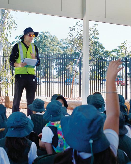
The location of the new Advanced Water Recycling Plant has meant careful planning and delivery continues to be important.
The site is located in the Perth suburb of Craigie, on Water Corporation-owned land that houses the original Advanced Water Recycling Plant and associated infrastructure from stage one of the Groundwater Replenishment Scheme. This stage continues to recharge water while stage two is under construction.
The proposed route for the pipeline was selected with a number of considerations in mind, including impacts to the community, environment, safety (of people constructing and maintaining the pipeline), constructability and cost.
At each recharge site, Water Corporation will be installing a total of four bores, including two recharge bores and two monitoring bores. Work to install these bores will involve drilling and construction of above-ground infrastructure. The work will be delivered in stages.
Work to install the bores at both the Wanneroo and Neerabup sites has begun and is expected to finish later this year. Work on the associated above-ground infrastructure will begin after the bores are completed and are expected to be completed early next year.
Pumping water back into Perth’s aquifers
The Clough-Suez Water Partners joint venture was awarded the contract to construct the Advanced Water Recycling Plant in October last year, and is also responsible for procuring the pumping equipment for the project. A spokesperson for Water Corporation said there were a number of pumps being used through the treatment process at different stages. These include:
• Digital dosing pumps and pneumatic diaphragm pumps for chemical transfer and dosing
• End suction centrifugal pumps for CIP, UV feed, UF feed, UF backwash
• Progressive cavity pumps for analyser panels
• Axially-split case centrifugal pumps for RO feed
• Transfer and recharge pumps
• Vertical multistage centrifugal pumps for service water
• Wet well submersible pumps for the feedwater pumps and sump pumps
“With all pumps, material compatibility with the pumped liquid is the principal concern.
"Generally speaking, for larger pumps energy efficiency is an important factor,” the spokesperson said.
“For smaller pumps, the most important factor is the initial cost as it forms a large proportion of the whole-of- life cost.”
When complete in 2019, the scheme will have the capacity to recycle enough water to supply up to 100,000 households per year, providing Perth with a new climate independent water source to boost much needed drinking water supplies.
Inside the Advanced Water Recycling PlantPumps involved in the Groundwater Replenishment Scheme include:
• Feedwater pump station – feeding water from the wastewater treatment plant and through the 1mm coarse screens
• Ultrafiltration (UF) feed – pumping through the 200um fine screens and the UF skids
• Reverse Osmosis (RO) feed – pumping through the Reverse Osmosis skids and the degassing towers
• UV Feed – pumping through the Ultraviolet process
• Transfer pumps – for pumping to the remote recharge sites
• Recharge pumps – for recharging the aquifers
• Monitoring bore pumps – for groundwater monitoring
• Development bore pumps – for re/development (cleaning) of the bore
• RO flush pumps – for flushing of the RO skids on skid shutdown
• UF backwash pumps – used during the cleaning of the UF skids
• Service Water – supplying the various cleaning systems
• UF and RO Clean in Place (CIP) systems – for chemical cleans of the process equipment, and subsequent neutralisation of chemical
• Analyser panels – pumps to online analysers of process water
• Chemical dosing and transfer panels – for transfer and dosing of chemicals for the CIP system and process


Brands
Kelair stock a wide range of high quality pump brands. Find the Brand you’re looking for.

Industries
From mining to pharmaceutical, Kelair has an extensive range for applications across all industries.


Type
Whether you need Positive Displacement Pumps or Centrifugal Pumps, we’ve got one that will hit the target.

Service
All our pumps are supported by our highly skilled service division for all your service needs.
When pump knowledge matters, turn to Kelair Pumps Australia. Visit us at www.kelairpumps.com.au
Sydney’s new aquatic centre set to make a splash

The Gunyama Park Aquatic and Recreation Centre sits within the 278-hectare Green Square development area, which includes the suburbs of Beaconsfield and Zetland, and parts of Rosebery, Alexandria and Waterloo.
On completion the Gunyama Park Aquatic Centre will feature a 50m outdoor pool as a centrepiece within a larger, irregular shaped beach pool. A 25m heated indoor pool for swimming lessons and a hydrotherapy pool will also be constructed.
A cogeneration scheme will heat the pools and supply electricity throughout the complex.
Key highlights of the complex include:
• 50m heated outdoor pool set within a larger, irregular shaped beach pool
• 25m indoor heated program pool
• Indoor leisure pool
• Heated hydrotherapy pool
• A crèche with indoor play areas
• A health and fitness centre
• A multipurpose synthetic sports field suitable for use by community sporting teams
• Sports field change rooms, public toilets and storage facilities
• New landscaping, lighting and a new public artwork by acclaimed Aboriginal artist Jonathan Jones
Work is underway on the $84 million Gunyama Park Aquatic and Recreation Centre in the City of Sydney’s Green Square precinct, and is the largest pool complex to be built in the city since the Sydney 2000 Olympic Games.

Inspired by the beach
In 2014, the City of Sydney held an open architecture competition to find the most beautiful, functional and sustainable design, with 144 architects submitting designs which were exhibited for public feedback that was used in the jury’s deliberations.
Andrew Burges Architects in association with Grimshaw and TCL created the winning design – an urban beach pool concept seamlessly integrating into a park inspired by beach pools at Bondi, Bronte, South Curl Curl and Malabar.
The design will be brought to life by CPB Contractors, who were awarded the construction contract in January 2018.
CPB Contractors Managing Director, Juan Santamaria, said they were pleased to be selected to build the new aquatic and recreation centre following an extensive competitive tender process.
“Our team has both the local and international expertise and project experience to deliver significant value for the City of Sydney,” Mr Santamaria said.
“Our flexible, multipurpose design will ensure that Gunyama Park is able to host a variety of activities, welcome locals and visitors from across Sydney, and remain adaptable to the city’s future growth requirements and sustainability expectations.”
The heart of the aquatic centre
Pumps are the heart of a swimming pool and are used to circulate the water through the filter to remove large and small organic matter to keep pools clean and safe. As the pump moves the water around to help filter it, it also circulates water through the heater or heat pump, any water features, massage jets and plumbing, as well as circulates the sanitiser and balancing chemicals throughout the pool.

Heat pumps are also commonly used for swimming pools to ensure comfortable swimming temperatures all year round. These pumps work by transferring the heat from the outside air to the pool.
The most commonly used pumps for swimming pools are:
• Single speed
• Dual speed
• Multi speed
• Variable speed
Powered by cogeneration
The electricity and pool heating needs for the Gunyama Park Aquatic and Recreation Centre will be powered by a cogeneration plant.
Cogeneration – also known as combined heat and power (CHP) – is the production of two useful forms of energy, such as high-temperature heat and electricity, from the same process.
It offers major economic and environmental benefits because it turns otherwise wasted heat into a useful energy source. This greater efficiency means carbon dioxide emissions are cut by up to two-thirds when compared with conventional coal-fired power stations.
Cogeneration involves burning fuel – usually natural gas (or renewable gas) – in an engine, typically a turbine or reciprocating engine, which in turn spins a generator to create electricity.
Heat from this process is then recovered through the exhaust, water jacket and cooling circuits instead of being released into the atmosphere and being wasted. This heat is then distributed to meet the energy needs of a site.
Pumps are used throughout the cogeneration process to push waste heat through the system and then send the energy back to the site.
Cogeneration involves four steps:
• Electricity generation
• Electricity distribution to site
• Heat recovery
• Heat distribution to site

A pavilion housing a gymnasium and fitness studios overlooks the pools
Revitalising the inner city
The construction of the Gunyama Park Aquatic and Recreation Centre will be completed in two stages, as the city does not currently own all portions of the land on which the complex is planned.
The full aquatic centre, multipurpose sports field and landscaped areas will be completed by early 2020, with an expanded sports field, playground and further landscaping to be completed as the remaining land becomes available.
The project will target a five-star design and as-built rating from the Green Building Council of Australia.
The city is spending $540 million over the next ten years on extensive infrastructure and streetscaping works throughout the area, as well as new community facilities that also include a library and plaza, creative centre, childcare centre, and more than 15 parks and open spaces.
Sydney’s Lord Mayor, Clover Moore, said the new pool was an important addition for Green Square.
“Green Square is one of the fastest growing precincts in Australia, and we’re doing everything we can to make sure it is a wonderful urban neighbourhood with the services and facilities its residents and workers need,” Mr Moore said.
“I’m looking forward to seeing this exciting project take shape in the coming months and know the Green Square community will be pleased to see work begin on their new aquatic centre very soon.”
When fully developed, Green Square will accommodate close to 61,000 people living in 30,500 new homes, and provide around 21,000 permanent jobs.


LEGENDARY RELIABILITY. UNRIVALLED SUPPORT. CUSTOM ENGINEERED.


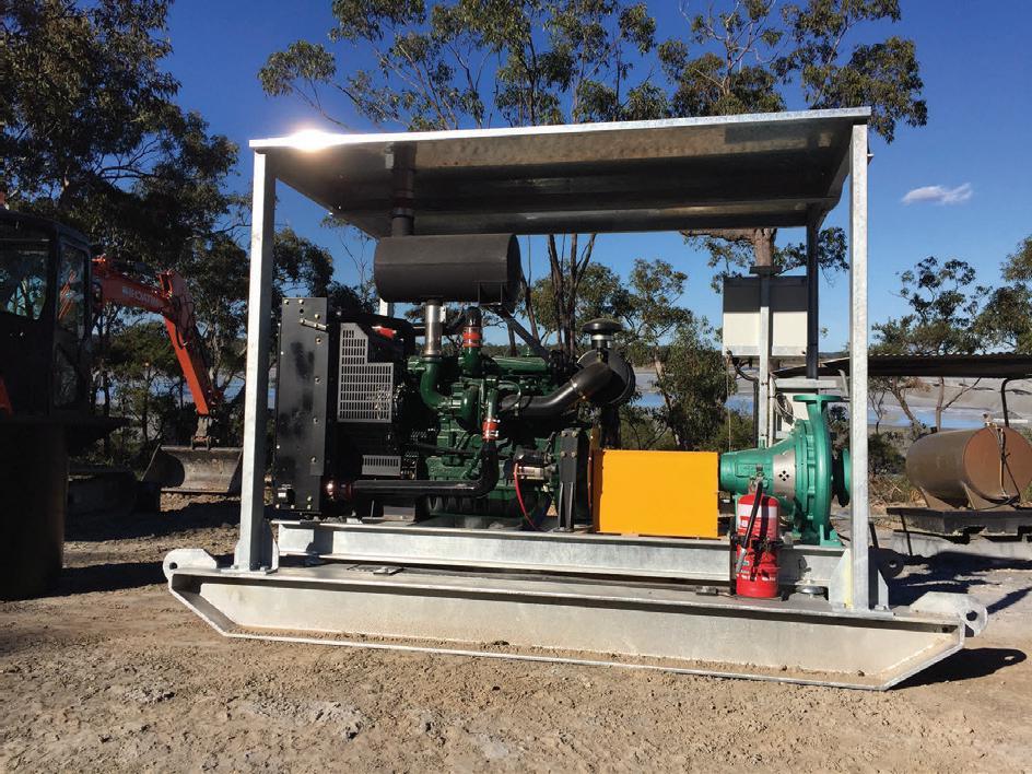
When the time comes to install a new irrigation system, or repower an existing one, insist on the legendary reliability of Isuzu engines. With a range spanning 18 models from 13HP to 284HP and a nationwide support network, we have you covered. Visit engines.isuzu.com.au
ISUZU ENGINE CONTROLLER PRO.
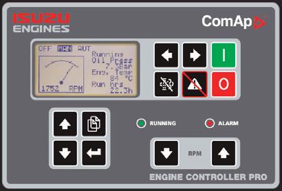
A cost effective, user friendly, customisable Engine and Irrigation Pump control, monitoring and protection system.
Available options:
• Pressure transducers
• Low coolant alarm/shutdown
• 160W Solar panel kit
• 3G/4G remote communication*
Visit our stand at the 2018 Irrigation Australia Conference and Exhibition June 13th to 15th, 2018.
• LINAK automated throttle actuators
• ComAp WebSupervisor application software

INVESTING IN WATER TO FUTURE PROOF WATER
With water security a top concern, Parkes Shire Council in New South Wales is planning ahead to future proof the community’s water supply by expanding infrastructure to draw water from diversified sources - including from dam, river and groundwater sources — replacing aging infrastructure, and increasing recycled water use. Here, we take a look at two projects that have been undertaken as part of a major water infrastructure project, a new water treatment plant and advanced water recycling facility.
Parkes Shire Council’s Integrated Water Infrastructure Renewal Project (IWIRP) is a multi-award winning project, having won top Water Management honours in the Local Government NSW Excellence in the Environment Awards, and the Sustainable Systems Award at the Blue Star Awards in 2017.
The IWIRP comprises multiple projects which will allow for more effective and extensive use of recycled water, and decrease demand on scarce water resources.
Meeting needs with a new water treatment plant
The new $45 million water treatment plant will provide a safe, secure water supply and ensures the community can continue to grow and attract new business and residents.
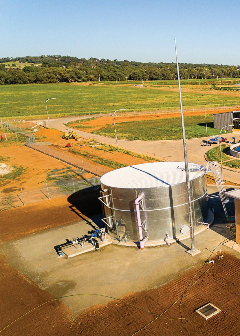
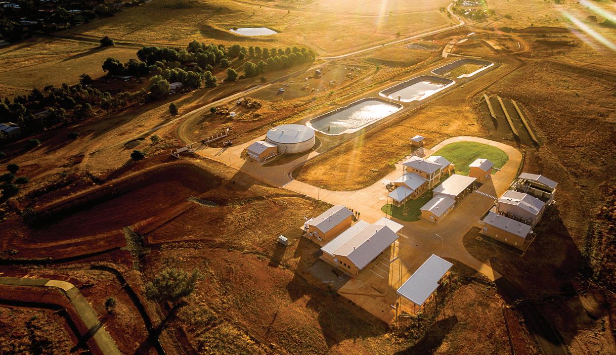
The project has completed the commissioning and proving phases and once fully operational in early 2018 it will take over from the existing water treatment plant at Albert Street. The existing plant was built in 1958 and is no longer able to cope and meet current and future water supply demands as it is too small. Technology has also improved since it was first built, so a new plant was required to continue meeting strict compliance standards on a consistent basis, as well as provide a more sophisticated system to blend and treat water from different sources.
The new water treatment plant is state-of-the-art, is fully automated with minimal operator supervision required, and uses the latest technologies for water production and water quality monitoring.
Parkes Shire Council’s Director of Infrastructure, Andrew Francis, said the main process train configuration underpinning the water treatment plant involves Flocculation, Dissolved Air Flotation-Filtration (DAFF), Chlorine Disinfection and Fluoridation.
Dissolved Air Floatation-Filtration (DAFF) is used for the clarification process to ensure smaller particles, such as algae from raw water, are effectively removed, and to reduce the amount of chemical dosing and eliminate the need for recurrent backwash.
As the plant is a ‘zero discharge’ process, the local waterways are not affected by wastewater released from the plant. The utilisation of gravity filters, the construction of a High Level Reservoir, and the installation of a 100MW PV system (solar panels) also means it has minimal power requirements.
An innovative procurement process
To maximise the value of the construction of the water treatment plant – as well as a sewage treatment plant – Parkes Shire Council adopted unique and progressive tendering strategy not usually undertaken by local government. Council used an Early Contractor Involvement process, and developed a framework in line with NSW Government procurement policy; incorporating Expression of Interest, Requests for Tender and Intensive Workshops as part of the selection process. This process gave Council confidence in
the cost of the projects and delivered a saving of $8 million, as project risks were mitigated.
Through the project procurement process, John Holland (JH) undertook its own procurement to inform its own tender submission.
“John Holland invited specialist pump vendors with proven track records to tender for the pumping packages comprising a mix of horizontal end suction pumps as well as submersible wet well pumps across the sewer treatment plant and water treatment plant,” John Holland Engineering manager Jim Livas said.
“The main factors that were considered when selecting the pumps were pumping efficiency, level of compliance to specification requirements, delivery time, availability of local support (service and maintenance), and vendor track record.”
The new water treatment plant is not only more efficient, it is also more productive. Most importantly, the new plant has double the capacity of the old plant, with the capacity to treat 16ML of water daily, ensuring the supply of quality water during peak seasons, and accommodating for projected growth.
The project was not without its challenges but Jim Livas said an extensive collaboration was key to overcoming these.
“The main challenge to the project was time related which was overcome with extensive collaboration between all stakeholders all focused on the same outcomes.”
INFRASTRUCTURE WATER SUPPLY
Improving security with recycled water
The Advanced Water Recycling Facility (AWRF) will underpin a new $21 million Recycled Water Scheme, strengthening water security and bringing recycling activities up to current regulatory and industry best practice standards.
The idea behind the scheme goes back to 2005, when recycled water was suggested as a potential solution to Parkes water security issues during community consultation.
The scheme will provide advanced disinfection of the high grade effluent from the new sewage treatment plant next door, to supply vastly superior water quality to customers on the existing effluent reuse scheme, and also allow recycled water to be used for irrigation purposes.
It is projected to result in water savings of up to 200ML and $20,000 per annum upon completion.
The Recycled Water Scheme replaces the existing Effluent Reuse Scheme; a long-running scheme that supplied low-quality recycled water for irrigation purposes.
The scheme is being rolled out in three phases:
Phase 1 was completed in December last year with completion of the construction of the new AWRF.
Phase 2 involves the construction of a specialised Recycled Water Rising Main to extend the delivery of recycled water to Parkes Shire Council's parks and greenspaces.
Phase 3 involves the potential expansion of the Recycled Water Rising Main to include additional third party commercial customers.
Building the Advanced Water Recycling Facility
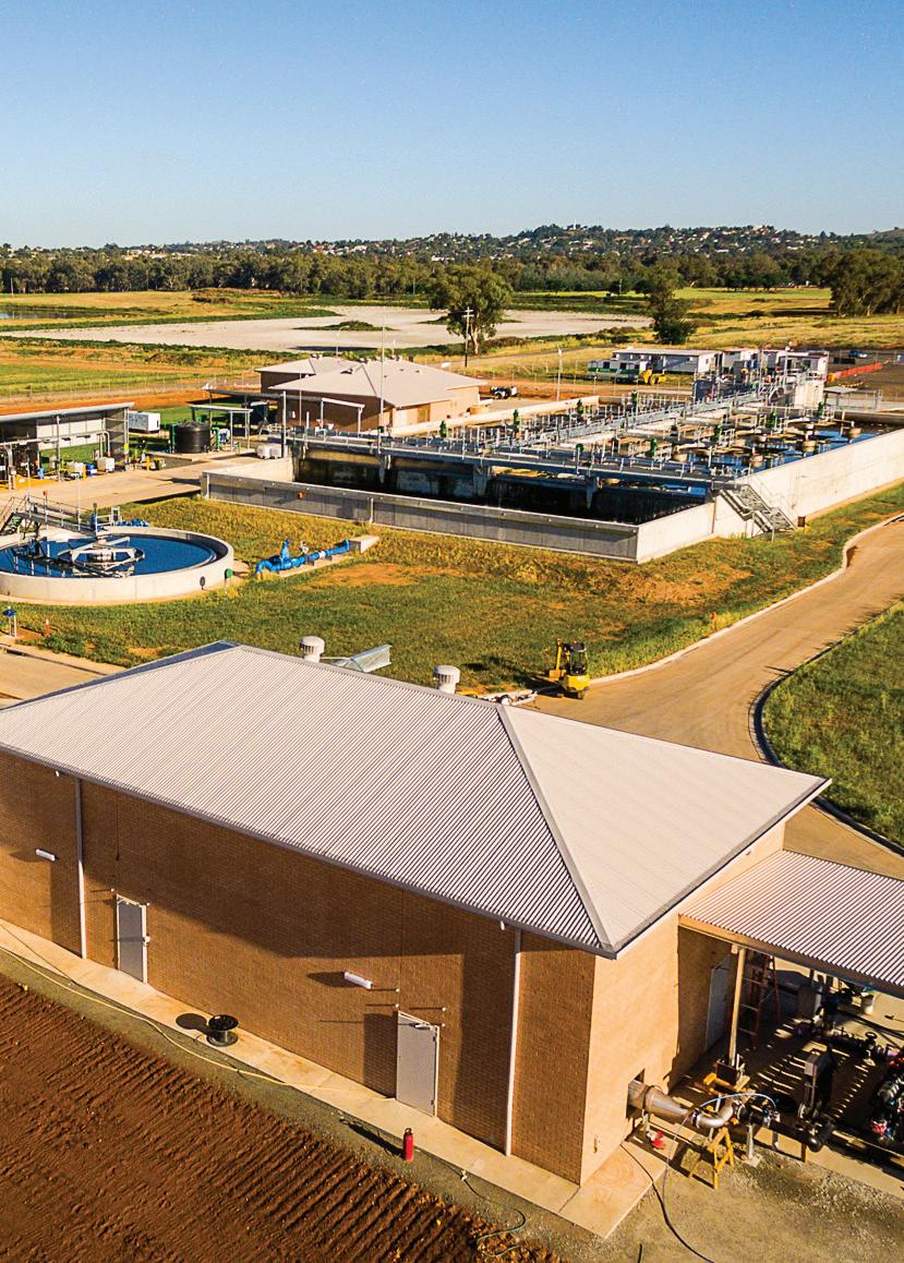
The Advanced Water Recycling Facility has been constructed alongside a new sewage treatment plant, and uses state-of-the-art treatment processes to purify the wastewater to the highest standard.
Parkes Shire Council's Director of Infrastructure, Andrew Francis, said, "The AWRF creates a new, local and completely drought-proof water supply that will keep our parks and sporting fields green – even during water restrictions.
“Our Recycled Water Scheme will achieve incredibly high treatment standards, to be solely used for irrigating our community greenspaces.
“This will reduce the demands on treated drinking water and lower Council’s operational costs.”
John Holland’s Engineering Manager, Jim Livas, said the heart of the state-of-the-art Advanced Water Recycling Facility comprises UV and Chlorine Disinfection.
“Tenders were invited for specialist equipment mostly related to pumps, screening, and UV. Prevalidated equipment was specified and vendors with proven track records were a significant consideration.
“Pumping efficiency, level of compliance to specification requirements and delivery time were important considerations when selecting equipment.”
The maintenance and repair schedule and costs also played a significant part of the overall TOTEX evaluation undertaken by the project team for both the Advanced Water Recycling Facility and water treatment plant.
There were no significant challenges during construction as the Advanced Water Recycling Facility was a greenfield add-on to the new sewage treatment plant, and allowances for integration had been made during the delivery of the sewage treatment plant which facilitated a seamless transition.
Bringing it all together
Along with the construction of the water treatment plant and the Recycled Water Scheme, other works have been undertaken to compliment these facilities and ensure they are efficient.
Lake Endeavour Dam upgrade
Construction works have been completed at the Lake Endeavour Dam on a $12.2 million project to strengthen the embankment and spillway to ensure long-term stability and integrity, and widening/deepening the existing spillway and raising the embankment crest to increase flood security.
Urban Water Mains Augmentation
As part of the new water treatment plant, several sections of raw and treated water pipelines were replaced as they were nearing the end of their useful life and their integrity was compromised, resulting in water loss due to cracks and breaks.
These pipes needed to be replaced to ensure water is delivered efficiently to the new treatment plant.
Lachlan River Pump Station and Bore 8 upgrades
$3 million in upgrades and refurbishment works have been undertaken at the Lachlan River Pump Station and Bore 8 to improve the capacity for water extraction, enabling the spread of water extraction across a number of sources, and reducing the impacts on individual water bodies.
KEY LEARNINGS
The works make the Lachlan River Intake a permanent water source, increasing the security of the raw water supply, and maintaining the community’s newest water source.
The refurbishment of Bore 8 on the Lachlan River in Forbes will optimise sustainable extraction from the borefield by spreading the drawdown of water over eight sites, minimising impact on the aquifer, allowing increased capacity.
• Early contact with authorities is beneficial to ensure timely approvals
• Open, clear, and direct lines of communication should be implemented to ensure that work interfaces are understood and agreed by all parties
• It is advised to include 'hold points' in contract documentation for environmental and sustainability outcomes to prevent incidents from occurring Contractor and client monitoring are best synchronised
• Create and use a central database for all monitoring data
• Ensure selected vendors can adequately support their equipment locally and respond in a timely manner.

SOLAR PUMPING: economic and environmental rewards
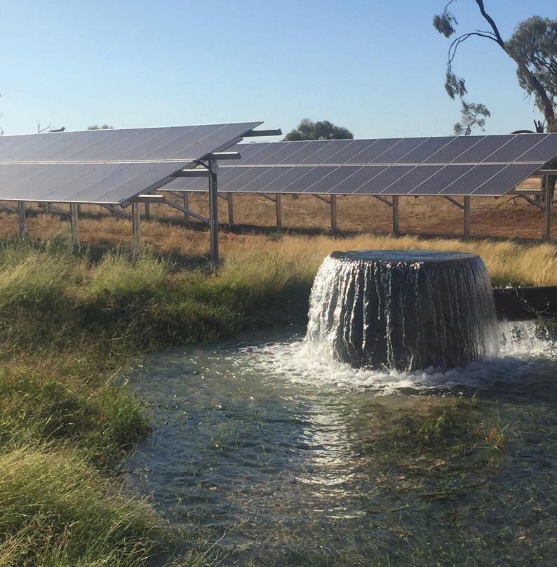
The installation of a solar diesel hybrid irrigation bore pump on a Central West NSW farm has led to big cuts in fuel costs, greater irrigation efficiencies and a massive reduction in greenhouse gas emissions.
Attracted by the drop in the price of solar panels in recent years and the prospect of the system paying for itself in less than four years, Andrew Gill and his family decided to install a solar diesel hybrid system at one of the pump sites on their Narromine farm.
The move has led to a cut in pumping costs from $76/ML to $41/ML, and slashed diesel use by between 45,000 and 55,000 litres a year. Over 25 years, that equates to a saving of more than 1 million litres of fuel and a reduction of over 3000 tonnes in carbon emissions.
CottonInfo Technical Lead Jon Welsh and Research Economist Janine Powell worked through project economics costings and carbon emissions profiling with the Gill family during feasibility.
“If potential productivity gains and environmental benefits exist, we need to share this technology and information with industry,” Mr Welsh said.
Mr Gill said while the environmental achievements were important, the clincher was the economic viability of the project which promised a quick return on investment.
“Diesel prices are the lowest they have been in 12 to 13 years, but it is not going to be cheap for the next 20 years, it is only going to go one way, and that’s up,” Mr Gill said.
“Solar is a way for us to have a better handle on what our input costs are going to be throughout the next 20 years of production. It is not often you can get that.
“For people who can use solar energy every day it is just mad not to do it.”
The Gills run sheep and cattle, and grow summer and winter dryland and irrigation crops, including 300 hectares of cotton each year.
They have no access to river water, only bore water. Their irrigation pumping system has traditionally been run exclusively by diesel pumps.
“For the past few years we have been trying to get better fuel efficiency out of
our diesel turbine pumps,” Mr Gill said.
“We found our turbines were at their highest efficiency point already. We couldn’t really achieve much more efficiency, so we looked at cheaper ways to get the water out of the ground.”
They decided to install the solar diesel hybrid system at one of their bore sites that provides year-round pumping into a large irrigation reservoir.
The new installation consists of 400 solar panels on four banks, producing 100 kilowatts of power to run a 55kW submersible pump that is being driven by a 70kW variable frequency drive.
Being a hybrid system, the pump is run on solar energy when there is sufficient irradiance from the sun, then switches to a diesel generator when the irradiance falls away.
“The diesel is more than just a backup. It allows the pump to run 24 hours a day in the peak pumping time,” Mr Gill said.
“The generator runs for about 14 hours a day when 24 hour pumping is required, but it also allows us to pump in a more cost effective way during the shoulder periods when the solar is not at maximum capacity, like first thing in the morning and in the early evenings.

“It is during these shoulder periods that we are able to blend the partial solar power with the diesel generator to pump water at a fraction of the diesel cost per megalitre.”
Mr Gill said he was continuing to look into ways to fine tune the system and improve its efficiency.
“We are planning to pump with solar over the winter but also using the generator to capture the shoulder periods to have our reservoir full for the start of the summer watering period. We might be more inclined to irrigate wheat (in the winter) if the water is on-hand and a bit cheaper. With real
time monitoring data through the 3G network we can watch our groundwater levels, troubleshoot remotely and quantify our diesel inputs far more accurately. It gives a lot more options.”
Likewise, he is weighing up the option of adding full battery storage to the system.
“It is a bit too expensive at the moment for what we are doing,” Mr Gill said.
“With the leftover energy we can produce through the day we can only really power about four extra hours a night of pumping production. With current storage prices that would be
somewhere between an eight and 10-year payback which is too far out for us at the moment.
“But battery storage prices are coming down. We are looking to see if there is a way of incorporating some battery storage into our system to stop the solar fluctuations through the day.”
Convinced that solar is the way of the future, Mr Gill plans to introduce more solar pump stations throughout the farm.
This project has been supported by funding from the Australian Government.
Reducing irrigation energy costs with variable speed drives
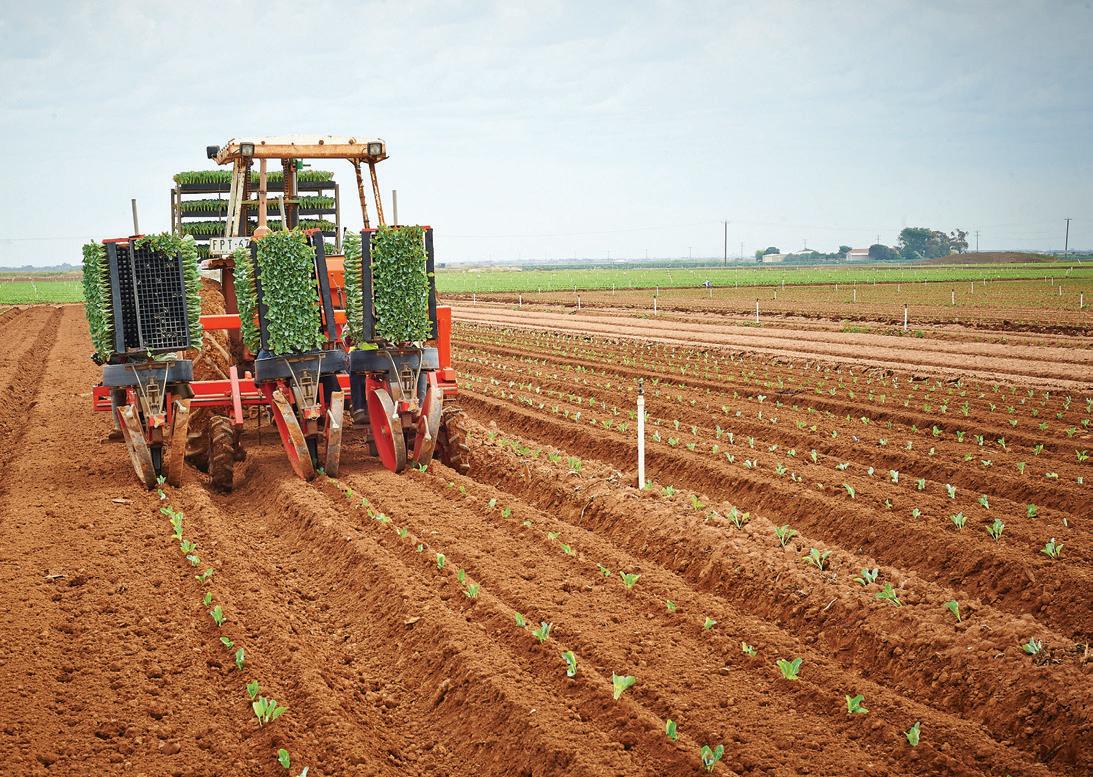
Variable speed drives (VSDs) offer energy savings for irrigators. In the past, operational needs informed pump selection decisions to use VSDs. Now as energy prices continue to rise, the opportunity to save costs is driving adoption of the technology. NSW Department of Primary Industries - Agriculture, Water and Irrigation Unit explains how VSDs can reduce operating head and energy usage in pumping plants.
Costs of irrigation
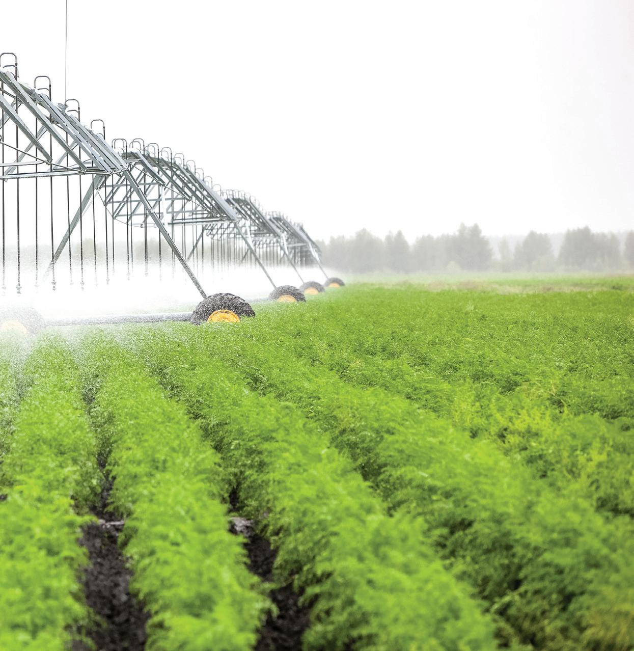
Three main factors adding to pumping costs and energy usage:
1. More water than necessary is being pumped and applied to a crop
2. The pump is operating away from its best efficiency point (BEP)
3. The pumping pressure, or operating head produced, is greater than necessary
Each of these issues can potentially be solved with the installation of a VSD system.
High and low demand pumping
Single speed pumps may be installed for a range of duties — usually sized to meet the greatest output demand. For lower demand use, these pumps will be oversized and operate inefficiently. Energy cost savings can be delivered by using variable speed to regulate the power needed to drive the pump, according to the duty. VSDs allow the pump to be over-designed to meet extreme requirements, without having continuous energy wasted during low demand.
VSDs allow small, rapid and regular variations in pump speed. VSD systems are often a viable option for pumps in highly variable demand situations, such as sequentially delivering water to irrigation units of variable sizes and elevation, and more frequent operations such as filter backflushing. VSDs offer convenience and great potential for energy cost savings if flow adjustments are required during irrigation.
The most popular and cost-effective
type of irrigation VSD is the variable frequency drive (VFD), which controls electric motors by varying the frequency and voltage supplied. Other options include multi-pump VSD systems, which can cater for very small to large flow rates.
Potential energy savings realised
As soft-start devices, VFDs have ramp-time adjustments for slow start and stop, can eliminate the problems of water hammer and excess power draw on start-up, and reduce or avoid flow or pressure surges. Reductions in speed can also reduce pump wear, particularly on bearings and seals.
Hydraulic optimisation, such as installing low pressure filters or driplines, can also lower the operating head, but unless the pump has the ability to respond to this lower head, energy savings will not be achievable. VFDs can respond and deliver potential energy savings.
Agronomic benefits
A VFD allows managers to adjust pumps to automatically suit conditions, eliminating unnecessary water delivery to irrigation patches. This improves irrigation scheduling, avoids rootzone waterlogging and water wastage, and increases the potential for high production, while keeping energy costs down.
Taking advantage of positive suction head
Some communal irrigation supply districts (e.g. Coomealla and Curlwaa in
the Sunraysia, and Leeton and Griffith in the Murrumbidgee Irrigation Areas) have a level of positive suction head delivered through a pressurised supply main.
When re-pumping is required to achieve a particular pressure and flow (duty point), a VFD makes best use of the supply pressure available. The level of supply pressure is often variable between and within irrigation events, making more permanent options such as fixed changes to pump speed (RPM), unattractive alternatives.
In a study conducted in Coomealla in 2011, it was found that if reasonable supply pressures are available at an outlet (100 kPa or greater), it was worth considering installing a VSD to take advantage of this supply pressure and reduce energy costs.
The study found VSDs reduced power consumption with increased inlet supply pressure had no effect on pumping efficiency or power consumption of fixed single speed pumps.
Although a fixed single speed pump requires less power when operating at low flow rates, power consumption was found to still be considerably higher than that of a variable speed driven pump at the same flow rates.
What to know before installing VSDs
Water supply
VFDs make it possible to achieve the very low flow rates that some irrigation systems might require. However, it is important to be aware that water meter accuracy can sometimes be
compromised at very low flows (e.g. 150mm propeller meters are inaccurate below 9 L/s) and approval from water supply authorities for diverting such low flows might be required.
Cooling
Cooling has been a particularly important consideration in the past, but new VSD technology now proves simple ventilation and insulation adequate in most cases. In some situations, the pumping unit is deliberately oversized to ensure less heat is generated. Some manufacturers now produce a ventilation attachment to electric motors to provide necessary cooling.
Hydraulic
To fully allow for the variable pressure requirements that can exist in an irrigation system, there should be at least two transducer set points. This is particularly the case for drip irrigation where a certain pressure is needed to operate the irrigation system, and higher pressure is required when backflushing filters and operating the system simultaneously.
One transducer set point located upstream of the filter bank, synchronised with timed backflushing, is required to increase the pump speed to meet backflushing requirements. Another transducer set point is located at a representative point in the field to ensure enough pressure is produced to operate the system. Further transducer points can be an advantage in irrigation systems where large elevation or spatial variations occur.
Pump efficiency
It is important to note that a VFD does not improve the pump efficiency. It simply reduces input energy requirements by producing the flow and pressure combination required at a particular operating time. Replacing worn pumps or impellers, trimming impellers and replacing mismatched pumps can improve pump efficiency.
When a VFD slows a pump down, the reduced flow rate can actually result in the pump operating less efficiently. However, energy use is still reduced, resulting in an energy cost saving. If the irrigation system requires significant flow rate variations or experiences frequently variable supply pressures, then using a VSD to slow
down and speed up the pump regularly in response will usually result in the greatest energy savings.
Managing the installation
VFDs can be retro-fitted to existing systems or installed with new systems. No two irrigation systems are alike, and no two VSD requirements are the same. The unique hydraulics of the system must be correctly merged with the unique electrical requirements for every situation. Specific issues for each situation involve identifying the appropriate location and setting of transducer set points.
There are instances of VFD equipment installation where the installer hasn’t realised the intricacies of the hydraulics and pump performance, resulting in a system that is energy inefficient. It is highly recommended that a professional pumping hydraulic design service evaluates your irrigation system before VFD equipment is purchased. It is also important that VFDs are commissioned correctly and all the safety cut-outs are set and tested. These are often overlooked, causing major issues over time.
VSD benefits NSW drip irrigation system
Andy Murdoch owns an 18 hectare vineyard, irrigated in four sections, in Coomealla NSW. With each section a different size, it required constant manual pump adjustment as the irrigation system did not allow for automated changeovers. The installation of a variable speed drive allowed this adjustment to occur automatically between different vineyard sections.
The Coomealla Irrigation Area, near Dareton in south-western NSW, supplies irrigators with moderate to high supply pressures through 75km of communal pipelines. A further advantage of VSD for this grower was a way to take advantage of the pressure available through the delivery system, resulting in further energy savings. It was determined that there was no other way of taking advantage of the moderate to high supply pressures provided in Coomealla. Basic cost calculations proved that installing a VSD would provide a very quick return on investment.
An Allen Bradley Powerflex 753 with
two transducer settings, 275 kPa for backflushing, and 170–200 kPa for drip system operation was installed. Gravel filters backflush for 90 seconds every 90 minutes. For cooling, the entire 5x9x3m pump shed was lined with foil board (Figure 1), with two ‘whirly birds’ installed in the roof. The shed was lined to ensure temperatures did not exceed 30 degrees.
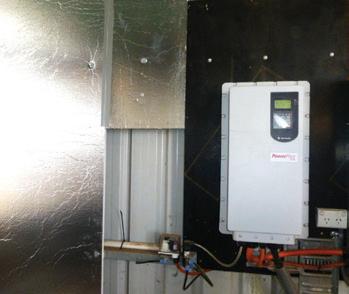
Some adjustment on downstream pressure setting was needed with assistance of the internet download from the supplier, the issue was resolved.
In the first year following installation, the average daily energy usage for Mr Murdoch’s vineyard dropped 39 per cent, even though 27 per cent more water was used and pumped to meet crop water requirements compared with the previous season. This was a power saving of approximately $4,000 for the year. The VSD cost $12,000.
Is a VSD system right for me?
When considering a VSD, it’s important to recognise that no two irrigation systems are alike.
Contractors must recognise that all situations are unique, and communication is needed between electrical contractors and irrigation designers. It is also important to note that VSDs are not needed in all situations. Determine how variable the pressure requirements are in a situation to determine the benefits of a VSD. If duty requirements do not vary, resizing the pump or trimming the impeller might be more viable options.
This is an extract from the NSW Department of Primary Industries Agriculture Water and Irrigation Unit’s Primefact ‘Variable speed drives — an energy-saving option for irrigated horticulture’. Acknowledgements to Jeremy Giddings Irrigation Industry Development Officer (Horticulture), Graham Hall, GH Electrical, Mildura Vic; Graeme Zanoni, Mildura Irrigation, Mildura Vic; Robert Welke, Tallemenco Pty Ltd, Adelaide (Pumping & Energy; Hydraulics Consultant); Peter Smith, Sapphire Irrigation Consulting - former Irrigation Development Officer, NSW DPI, Tamworth. For more information visit www.dpi.nsw.gov.au/land-and-water/water/irrigation.
Successful future with new generation diesel engines
HATZ Diesel Australia has released a new generation of water-cooled and turbocharged diesel engines to complement its existing air-cooled range of engines.
HATZ is one of the major suppliers of air-cooled industrial diesel engines in Australia and New Zealand, and its parent company in Germany has been manufacturing engines for over 130 years, developing into a specialist for diesel engines rated up to 62kW.
This new engine family extends the HATZ product portfolio with the H-series, allowing customers to choose the best diesel engine for their needs from six families and over 20 different models between 2-62kW.
Complementing the recently released 4H50TI and 4H50TIC 4-cylinder engine models, is the upcoming 3H50TI and 3H50TIC 3-cylinder versions. HATZ is relying on commonrail technology, turbocharger and external exhaust gas recirculation.
This new range of engines excels as a compact, lightweight and robust design, setting new standards in the performance class up to 62kW.
This engine is equipped with a BOSCH Common-Rail system for excellent fuel efficiency.
Other benefits of these engines are lightweight, compactness, high torque and low vibration.
For over 30 years, HATZ Diesel Australia has supported the Australian market by providing quality products, unmatched spare parts supply, and the best service support anyone could ask for.
Manufactured under stringent quality control to ensure reliability and durability, HATZ diesel engines are truly heavyduty industrial units designed for construction equipment, irrigation pumps, travelling irrigators and generating sets.
Regardless of whether your requirement is water pumps for irrigation plants or emergency power generators for complete building complexes, HATZ has an engine for you. Thanks to its air-cooling and rugged construction HATZ engines can be used everywhere, even in the most adverse conditions.
For specification brochures, technical information or a more comprehensive look at HATZ Diesel Australia, please feel free to visit its new website located at www.hatz.com.au.

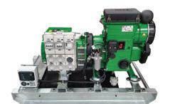
GENSETS
HATZ custom designs and builds gensets. Ideal for submersible bore pumps and travelling irrigators.
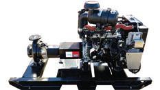
PUMPSETS
HATZ offers a coupling and design/fabrication service for pumpsets, so you get peace of mind.

CENTRIFUGAL PUMP MOTOR SELECTION, INSTALLATION AND START UP
By Joe Evans, Pump Ed 101It has been my observation that the vast majority of new electric motor failures can be attributed to improper selection, installation and start up. Although factory defects do occur, they are rare and tend to be quite apparent when a failed motor is inspected. The following is a short guide to proper selection, installation and start up of new and replacement centrifugal pump motors.
Selection
New Installations
Many of us assume that a new pump will be mated to the proper motor at the factory but this is not always the case. More and more commercial installations tend to be WYE connected and utilise 208V rather than the 230 or 460V offered by Delta transformers. Also, the pump manufacturer will often use a portion of the motor’s service factor to meet the required head and flow. Both of these conditions can lead to a factory supplied motor that is incorrect for the application.
A motor’s service factor is defined as a multiplier that, when applied to the rated horsepower, provides the maximum permissible loading at rated voltage. Most pump motors are supplied with a 1.15 service factor and, in an ideal situation, a 10HP model can be loaded to 11.5HP.
Standard single phase motors are designed to operate on 230VAC while three phase models are usually wound for both 230 and 460VAC. Both will operate at 208VAC but, in doing so, their service factor is reduced to 1.0.
In the case of a centrifugal pump, the service factor’s primary purpose is to protect the motor during low voltage conditions. If that service factor is
already being consumed by 208 volt operation, none remains to protect against a further voltage drop. This condition is further compromised when the pump loads the motor to its full load capacity.
In fact, some pumps actually use a portion of the service factor during normal operation (in order to lower initial cost) and, if this condition exists, 208 volt operation will eventually cause the motor to fail. Use of the service factor in 230V and 460V applications will also shorten motor life if low voltage conditions are common. If this could be the case, always order the pump with the next higher HP motor.
If the power source is a WYE transformer, it is always best to purchase a pump with a motor wound specifically for 208VAC since these motors maintain a full service factor. If a 208 volt motor is unavailable a common remedy is to select the next higher horsepower 230 volt model.
You will often hear that you should not oversize a motor because “under loading” will reduce its efficiency. Actually, the exact opposite is true. The typical induction motor reaches its maximum efficiency between 65 and 85 per cent load, and efficiency remains relatively flat between 55 and 90 per cent. When loading drops below 50 per
cent efficiency drops rapidly but, the amount of energy wasted is very low because the total power used is also very low. So, if you want to get the most efficiency out of a motor, use a 100HP model to drive that 75HP load. You may also double its life.
Replacement motors
When replacing a centrifugal pump motor, it is important to select one that has the same voltage and service factor. This is especially true in the case of small single phase motors where the service factor may be quite large. For example, a typical 3/4HP jet pump with a 1.45 service factor actually has almost 1.1HP available. If it were replaced with a standard 3/4HP, 1.15 SF motor it would overload and eventually fail. Again, if a motor with the proper service factor is unavailable, select the next higher horsepower model.
Installation
If a complete pump or replacement motor (especially large frame motors) has been in storage for an extended period of time, an extensive inspection should be performed before placing it into service. Minimally this should include a visual inspection, a megger test, and a bearing inspection. It is



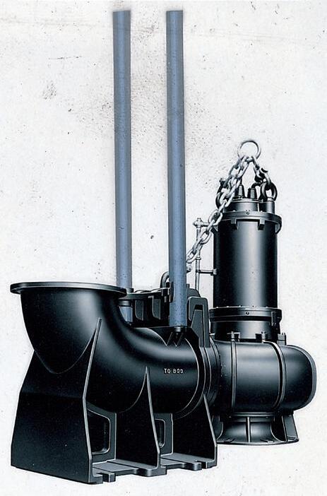
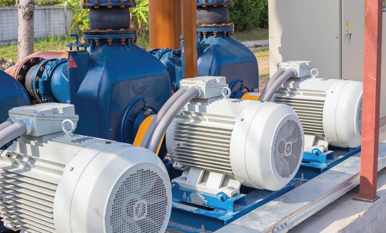
Single phase motors
Wire the motor leads as shown in the wiring diagram on the nameplate. Fractional HP, dual voltage motors often incorporate a switch for voltage selection while some still require removal or rerouting of a jumper. In either case, make sure the proper voltage is selected. Running a single phase motor on the wrong voltage will quickly degrade the winding insulation. Some single phase motors are also bidirectional so ensure that the leads are connected for proper rotation. Rotation (CW/CCW) is determined by viewing from the rear (non-shaft end) of the motor.
Thermal protection is provided internally on most fractional HP motors. A bimetal switch embedded in the stator windings interrupts power if the windings overheat. Larger motors, usually 3 HP and above, are not internally protected. These units require a combination starter/overload relay for protection. Both components must be capable of accommodating the service factor load of the motor. Installation without this device will void the motor warranty.
Three phase motors
Wire the motor leads as shown in the wiring diagram on the nameplate. Standard three phase motors are usually dual voltage and incorporate six or nine leads. The operating voltage is dependent upon the configuration of these leads, and stator winding damage can occur if they are misconnected. Double check the diagram once you have completed the connections. Three phase motors cannot be prewired for a particular rotation and there is a 50/50 chance that it will be correct. If rotation is incorrect it can be corrected at start
up. It is also a good idea to check the stator winding resistance's among the three leads (L1/L2, L1/L3, L2/L3). The resistance in ohms should be the same for each combination.
All three phase motors require a combination starter/overload relay. In addition to overload protection, the IEC versions of this device also protect against phase loss and phase imbalance. Make sure that the contactor and overload relay are matched to the motor’s service factor amperage for the operating voltage selected.
Start up
Single phase motors
Before starting the motor, use a voltmeter to measure the source voltage and ensure that it is within normal tolerances. A 115V source should measure between 115 and 125V and a 230V source should measure between 230 and 240V. A 208V source should be between 208 and 215V. If lower measurements are detected the problem must be located and corrected before placing the motor in service.
Leave the voltmeter connected and place a clamp-on ammeter over one of the motor power leads. Start the pump and observe that the amp draw at various flow rates. It should not exceed the nameplate amperage of the motor. If the amp draw is higher than nameplate amperage, observe the source voltage while the pump is running. If the source voltage has dropped more than two per cent, the wiring to the starter may be too small or poor connections may exist. If the voltage has not dropped more than two per cent, check all wiring connections between the starter and the motor. In any event, locate the source of the problem and correct it before leaving the pump in service.
Three phase motors
As before, use a voltmeter to measure the source voltage. In the case of three phase power, voltage must be measured between L1/L2, L1/L3 and L2/L3. The voltage should be the same for all three pairs. An unbalanced line voltage greater than one per cent can cause motor overheating. A 230V source should measure between 220 and 240V, and a 460V source should measure between 440 and 480V. A 208V source should measure between 200 and 215V. If voltage is not within these ranges, the problem must be located and corrected.
Briefly start the motor and observe rotation. If it is not rotating in the proper direction interchange any two of the motor leads at the starter terminal block. After correct rotation has been established, use a clamp-on ammeter to measure and record the current draw of each of the three legs. These measurements should not exceed the nameplate amperage of the motor. Stop the motor and use the following procedure to calculate current imbalance.
1. Add the three measured current values
2. Divide the sum by three to obtain average current
3. Determine which of the three values is furthermost from the average
4. Compute the difference between this value and the average
5. Divide the difference by the average and multiply the result by 100 to get a percentage
If current imbalance is two per cent or less, the leads should be left as connected. If imbalance is more than two per cent roll the leads (in the same direction) one position at the starter and remeasure. Roll them again and measure the final hook up. Select the hook up with the least current imbalance.
Current imbalance should not exceed five per cent. If it cannot be corrected by rolling the leads, its source must be located and corrected. If, when rolling the leads, the leg with the greatest imbalance remains on the same starter terminal, the imbalance is due to the power source. If, however, the leg with the greatest imbalance moves with the same motor lead, the problem is on the motor side of the starter. Often it is due to a bad connection but, occasionally, a faulty stator winding is the problem.
VARIABLE SPEED DRIVES
Vacuum pumps are used to produce sufficient air flow to operate milk harvesting equipment and

The other two components, the milk pump and feed motors represent the remaining ten percent, respectively. Installing a variable speed drive on a vacuum pump will match the speed of vacuum pumps with the demand for air flow thereby lowering energy consumption and energy emissions, as well as noise in the dairy shed.
The technology
A variable speed drive (VSD) will produce the minimum reserve requirement only when there is extra demand for air flow, above what is required for operating the equipment. Energy savings will occur when there is no demand for the extra air flow.
Variable speed drives can be attached to new or existing vacuum pumps. Two commonly used vacuum pumps are oil vane and blower vacuum pumps.
Oil vane vacuum pumps need to operate at high revolutions to provide sufficient vacuum. In some cases they might not be suited to a VSD if the revolutions can not be lowered without wearing out the pump.
Blower vacuum pumps are more energy efficient than oil vane pumps but have a higher initial cost. Blower vacuum pumps are better suited to VSD as they can operate at lower revolutions than oil vane vacuum pumps whilst still maintaining sufficient vacuum. They
generally run quieter and have a longer life.
Some of the considerations for installing a variable speed drive include:
• Existing pump – the working condition of the existing pump can influence the potential savings, particularly older pumps
• Pump running time – the size of the dairy farm relative to the number of cows milked influences potential savings. The greatest gains can be made on longer running times
• Matching pump size with shed size –if the size of the pump is not matched to the dairy shed money can be saved by upgrading the pump and installing a variable speed drive
• Correct installation and machine
testing – full energy saving gains will be achieved when filter protections and components are properly installed and tested
• Dairy shed power type – single phase power may require a larger drive or inverter therefore drawing more power to run. Three phase power may be a better option
• Air consumption – different vacuum pumps with the same motor size (kW) can have different air consumption due to the layout of the system. Leakage of air in the system by incorrect installation can also reduce efficiency
• Motor speed of existing pump or revolutions per minute (RPM) –Greater energy savings are possible
IN THE DAIRY SHED
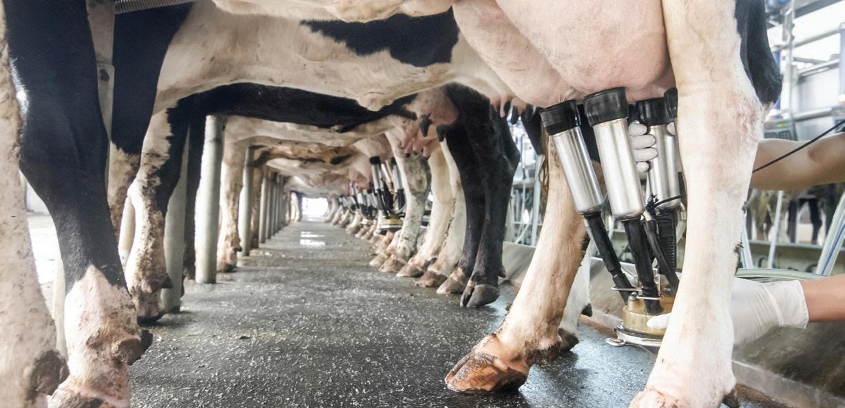
where the pump can operate at a lower RPM (e.g. half capacity), for example a 1,400RPM motor that can be geared down to 700RPM will benefit from installing a VSD.
The lower motor speed must remain above the minimum operating requirement of the motor to avoid unnecessary wear and early replacement.
Energy savings
Table 1: An example of the air flow on a 7.5kW oil vane vacuum pump for the minimum reserve requirement and operating equipment. This system was set to 50kPa.
There are opportunities to reduce energy consumption on vacuum pumps as they typically operate at a constant
speed regardless of the demand for air flow. The pump produces sufficient air flow to operate the milk harvesting equipment plus a minimum reserve requirement. When the minimum reserve requirement is not produced there is a 47 percent saving in energy (Table 1).
Table 2: Economic analysis of a variable speed drive kits on new and existing vacuum pumps.
*The new oil vane vacuum pump with a VSD installed did not recoup costs by the end of year ten.
The above hypothetical case study farm has a 7.5kW oil vane vacuum pump which generates 7.5kWh per hour. The pump operates for 2.5 hours per milking, with the first hour of weekdays on
represent approximately 80 per cent of energy used by the milking equipment components. For more information on pumps in agriculture, visit Agriculture Victoria’s website
off-peak time. The pump used 13,650 kWh and cost $2,535 in the first year.
The most profitable option was installing a Variable Speed Drive (VSD) kit on an existing blower vacuum pump. However a VSD is profitable on any existing vacuum pump.
New blower vacuum pumps were profitable investments whereas a new oil vane vacuum pump would not recoup the initial costs by the end of year ten. The energy savings in the new oil vane vacuum pump did not cover the capital and operating costs over the ten year period.
This suggests that a blower vacuum pump with a VSD installed is the preferred type of pump to replace an existing pump.

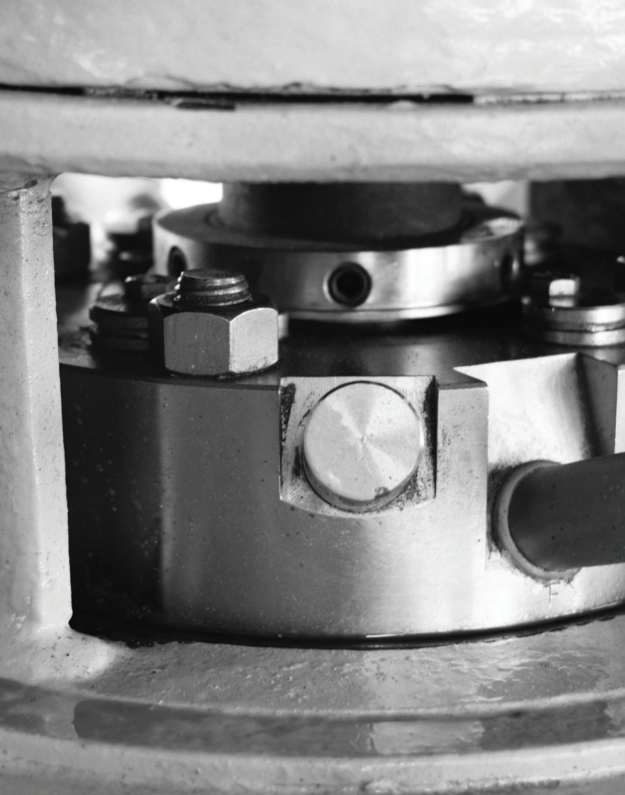
AA PUMP GUY RANT ON SEAL RELIABILITY
By Larry Bachus, The Pump GuyIndustrial Safety and Industrial Reliability were born together in the early 1970s, as twin children of Aviation Safety and Reliability. The aviation industry wrote the book on safety and reliability as the airline companies converted their fleets of passenger planes from propeller engines to jet engines.
viation safety revolves around passenger safety.
Aviation reliability revolves round equipment reliability. However, the goal of passenger safety is also the goal of equipment reliability, that is: a better experience.
Anything — night time runway lighting for example — that improves flight safety also improves flight reliability. Scheduled jet engine preventive maintenance improves both equipment reliability and passenger safety. A passenger jet that stays in the air and arrives at its destination on time without incident or accident is both safe and reliable. One hand washes the other hand.
The distinguishing factor between the aviation safety and reliability programs, and the industrial safety and reliability programs is: The workers (the flight crew) and customers (the paying passengers) ride inside the flying equipment. If the jet is reliable, the crew and passengers are safe.
In industry, with very few exceptions, the workers don’t ride inside the running equipment. Exception: The crane operator rides inside the crane. The bus driver with passengers ride inside the bus.
In industry, worker safety and equipment reliability have different goals. They are separate departments with separate goals.
In 2018, we can say that most process plants are safe. Companies brag about their safety statistics. The company officers enthusiastically support the safety program. The safety engineer proudly publishes the safety statistics in a company newsletter or on a prominent billboard. Everyone (visitors, contractors, part-timers, secretaries, company officers) gets training on “safety”. Everyone is encouraged to report an unsafe action or situation. Everyone practices and contributes to safety.
However, too many process pumps are not reliable. Too many reliability programs are stalled. Often, company officers don’t really support the reliability program. The reliability engineer doesn’t publish reliability statistics on pumps and other rotating equipment. Who, besides the reliability team, goes to the reliability meetings? No one is encouraged to report an unreliable action or situation. No one knows how to contribute to reliability.
Most process plants divide the assets into rotating equipment (pumps, motors, fans, compressors, gear boxes,
turbines, air extractors, etc) and stationary equipment (tanks, pipes, valves, heat exchangers, etc). Process pumps drag-down the reliability statistics.

Notice the trough under the seal chamber to carry-away leakage. The astute seal salesman calls this “Proactive”.
Most reliability people know and use the term ‘Bad Actor Pump’. Where are the ‘Bad Actor Fans’? Where are the ‘Bad Actor Transmissions’? You see, fans, motors and gearboxes don’t drag down the reliability statistics. Process pumps with mechanical seals drag down the reliability statistics.
The mechanical seal was patented 115 years ago in 1903. 1903 was the same year the Ford “Model T” automobile, and the Harley Davidson motorcycle went into production. The Wright Brothers initiated powered flight in 1903. And the screw-in electric light bulb was patented in 1903.
115 years later, electric lighting is mostly perfected even as it evolves into LEDs. Commercial aviation is mastered, safe and reliable. But over a century later, too many process pumps are not reliable because too many mechanical seals fail mysteriously, prematurely.
The automobile companies make large and small vehicles (cars, trucks, convertibles, off-road vehicles, minivans, motorhomes, sports cars, etc) for the needs of the driving
public. You’d think the mechanical seal industry would make reliable seals for the needs of the process industry.
How about a mechanical seal for pumps in cavitation? We need a mechanical seal for deadheaded pumps and dry-running pumps. We need seals designed for pumps that operate for extended periods on the extreme left or right of the performance curve. We need a seal for starved pumps. We need mechanical seals designed to handle production upsets. These are the real reasons that so many pumps suffer premature seal failure. Why doesn’t the seal industry recognise this?
And yet, the seal manufacturers continue to promote ‘easy installation’, ‘interchangeable spare parts’, rebuild kits and ‘off-the-shelf availability’. How about longer service life in a process pump? We don’t really need another seal that can be installed by an apprentice technician in five minutes… every four months.
“Service” is the word used at a stud farm for racehorses. The breed stallions “service” the receptive mares. Maintenance engineers are tired of being “serviced” by their seal suppliers.
Generally, pumps don’t break. Pumps leak! The impeller doesn’t split into five pieces. The shaft sleeve doesn’t fracture into three pieces. The seal chamber doesn’t crack. The volute casing rarely splits down the middle.
A process pump can overheat and continue pumping. Some pumps suffer cavitation for months and continue pumping. Pumps can vibrate wildly and continue running. This is called “Running-to-Failure” (a concept that deserves its own article.).
Pumps leak because the seal fails prematurely. Admittedly there are other pump problems (mentioned in the previous paragraph). Eventually, the excess heat, incorrect piping, wild vibrations, mechanical loading, cavitation, misaligned bearings, dry-running, deadheading and operational abuse will stress the seal until it unexpectedly leaks and fails. Then the pump goes into the shop.
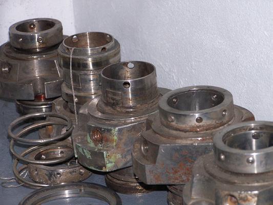
Mechanical seals leak either at the seal faces, or through the secondary elastomer component, normally an O-ring. I promise you the process liquid is not extruding through the seal’s stainless steel body, or through the set screws, springs

At Brown Brothers Engineers we have expanded our capabilities with two more quality pump manufacturers. In addition to the current world leading brands we can now offer the following range:
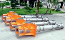
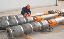

Layne Bowler
vertical turbine pumps have a proven record under the most demanding and toughest of conditions.

When high head and high flows are required look no further than this quality Italian made range.
• Flows to 5000m³/h
• Head to 220m
• Pumps that exceed EN733 (DIN 24255 standard)

SKD Series
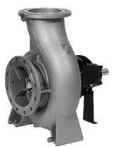
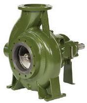
or drive pins. The drip doesn’t find a microscopic pathway through the non-porous ceramic ring. All leakage is through the union at the seal faces, or through the O-rings and/or gaskets.
40 years ago, no seal manufacturer was intimately associated with a pump manufacturer. But now, with corporate mergers and “team-playing” mega-conglomerates, a few companies have a pump manufacturer and a seal company in the corporate portfolio. The seal manufacturers and pump companies must jointly direct their efforts toward the sealface union, and the secondary elastomers.


Evidence suggests the seal manufacturers aren’t paying attention. We haven’t seen any great leaps in mechanical seal technology in recent years. There is more action in eliminating mechanical seals. Here are three examples.
Elastomer technology
Perfluoroelastomer O-rings have been around for almost 40 years. This elastomer compound can resist a broad range of aggressive chemicals and withstand temperatures up to about 300°C without degradation. To date I’m not aware of a successor O-ring. Where is the 400°C O-ring? Or the 600°C O-ring? Where is the O-ring with even broader chemical resistance?
Sealless pumps
This is actually a misnomer. Mag drive and canned motor pumps have seals, (O-rings and gaskets) but they don’t have a mechanical seal on the rotating shaft. We should correctly call them “mechanical sealless pumps”. Mechanical sealless pumps are available in a wide range of designs, covering PD and centrifugal types. Mechanical sealless pumps are thought to be a recent development. Actually, they are the oldest of designs. The Archimedes Screw had no seal on the rotating shaft.
Dry gas seals
The first dry gas mechanical seal is close to 70 years old (patented in 1951). These dry gas seals have performed well in rotary compressors since then. There are a few reasons for the success in compressors.
The range of gases that are typically compressed is limited. Examples are air, nitrogen, oxygen, hydrogen, hydrocarbon gases (propane, butane, natural gas, acetylene, etc), refrigeration gas, and CO2 as fire suppression gas. Also, the gas is normally filtered and free of solid particles and other contaminants as it passes through the compressor.
Containing a process gas with a compatible, pressurised barrier gas is relatively easy. Containing a dirty, abrasive, aggressive, non-compressive liquid with a barrier gas is another animal.
In the late 1960s, someone said, “Because dry gas seals work so well in compressors, why don’t we put dry gas seals into centrifugal process pumps?” To be politically correct, this seal has a “Long and Slow (30+ years and still counting) Learning Curve” in process pumps. There, I said it. Well someone needed to say it.
Dry Gas seals have an uphill battle in pumps as long as:
• Control room operators can’t interpret a pump performance curve
• Process pumps lack adequate instrumentation
• Process pumps are allowed to operate indiscriminately all over their performance curves in dynamic process systems
It makes no sense to install a mechanical seal where the axial gap required at the seal faces is stricter than the permissible axial play in the shaft bearings. What’s the purpose of a mechanical seal with a sophisticated support system that costs more than the seal itself? Isn’t this like a tyre that costs more than the car?
The fuse is the weak link in an electrical circuit. A burned fuse is the physical manifestation of a problem in the electrical circuit. The electrician doesn’t change the same burned fuse 20 times in the same circuit. The electrician doesn’t blame the fuse for failing. After two or three burned fuses, the electrician knows the problem and the solution is in the electrical circuit and not in the fuse or fuse box itself.
Likewise, the mechanical seal is the weak link in a hydraulic circuit. Numerous failed seals in the same pump is the physical manifestation of a problem in the hydraulic circuit. So, why does the maintenance engineer change the same failed seal 20 times in the same pump? Why does the maintenance manager blame the failed seal? The reliability engineer should do a failure analysis on every seal that fails prematurely to be sure the seal was specified properly and installed properly. After two or three premature seal failures in the same pump, the reliability engineer should search for the problem and the solution in the hydraulic circuit.
The Pump Guy is Larry Bachus, a maintenance practitioner, inventor, lecturer and contract mentor based in Nashville, Tennessee. Mechanical seals, seal failure and failure analysis are discussed in Larry’s book Everything You Need to Know about Pumps. Larry is a retired member of ASME, and speaks fluent English and Spanish. You can contact Larry at larry@bachusinc.com.
A POWERFUL PARTNERSHIP
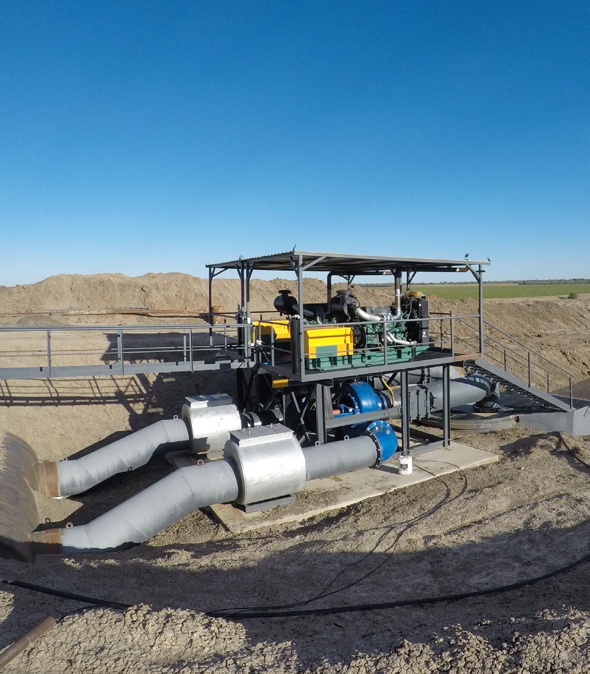
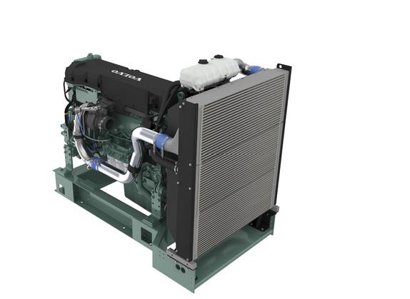
Volvo Penta. Robust, fuel efficient industrial diesel engines that keep running even in the toughest conditions. Easy to install, operate and maintain. A powerful partnership you can trust all the way from the drawing board throughout the operational life of your engine. Competitively priced complete power-pack units ready for delivery Australia wide with a local support team on hand 24/7. To find your nearest dealer visit www.volvopenta.com

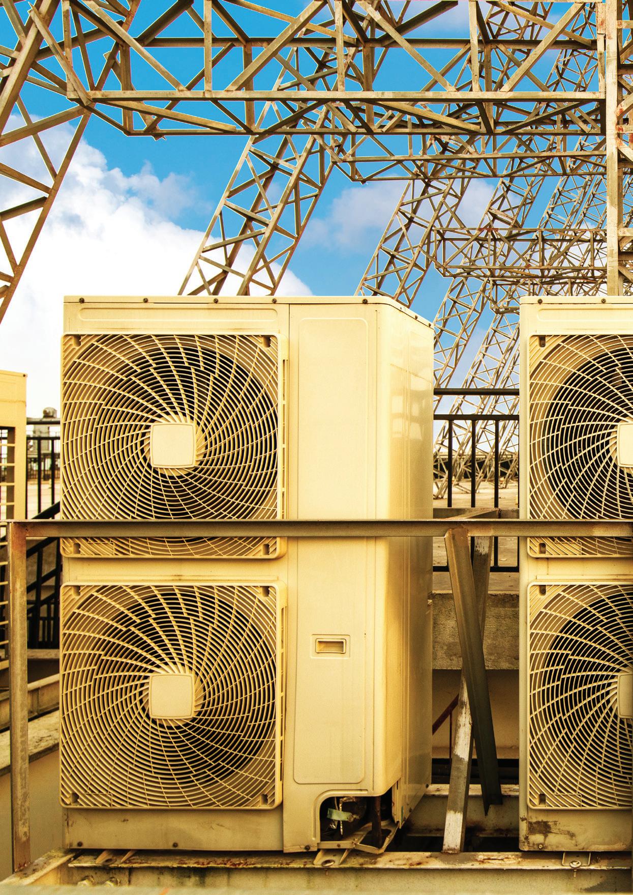
REVISING THE CODE: realising greater energy efficiency in HVAC
By Keith Sanders, PIA Councillor and Life MemberThe Australian Building Codes Board (ABCB) is in the process of revising the energy efficiency provisions in Section J of the National Construction Code (NCC). One area the review will look at and where energy efficiencies can be realised is HVAC. Here, we’ll look at the proposed revisions for the selection and design of HVAC systems in relation to pumps, and how these changes will impact the sector if implemented.
The project stems from Measure 31 of Council of Australian Governments' National Energy Productivity Plan, where the ABCB was requested to consider changes to the energy efficiency provisions for NCC 2019 in December 2015.
In April 2017, Energy Action approached Pump Industry Australia (PIA) to assist with a review of draft recommendations to the ABCB in relation to pumps used in HVAC systems, resulting in a revised report in August 2017 with some of the PIA recommendations included.
The report submitted by Energy Action focused on how the methodology for pump selection can be improved to achieve better pump and system matches that will lead to lower power consumption and improved equipment reliability.
Looking for ways to improve
To help with Energy Action’s review, the PIA Council approved the formation of a small sub-committee to investigate how pumping equipment in HVAC specifications is currently specified. The aim was to propose a methodology for ensuring the industry follows best practice in the design of HVAC systems to minimise energy losses and the selection of appropriate pumps, motors and control systems.
The sub-committee worked to prepare a practical recommendation based on the products known to be available in the Australian market. In addition, the PIA’s relationship with the British Pump Manufacturers’ Association (BPMA) allowed access to the latest information from Europump to determine if this could be adopted in Australia. This included a detailed look at end suction pumps in the ISO 2858 range and the EN 733, used extensively in this market sector and consideration of a minimum energy performance standards (MEPS) approach to these product ranges.
Considerations for review
The sub-committee looked at the issues that need to be addressed to promote the minimisation of energy consumption in HVAC systems. While this requires a “system approach” to achieve the maximum benefits, there are also benefits in proposing the use of products that are in the upper levels of efficiency by adopting MEPS approaches for pumps, motors and control systems.
1. Good system design is the responsibility of the HVAC contractor and sizing of pipework is a significant factor in minimising friction losses in the system. Limiting flow velocities is the preferred approach with 2-3 m/sec considered a reasonable target
2. Determining the principal pump duty needs to be undertaken carefully by HVAC contractors once the final system design is completed. Pump suppliers should be provided with sufficient information to allow for the
optimum pump selection. A better understanding of the preferred operating region (POR) on a pump curve needs to be promoted by using the “house of efficiency” approach. Flow rates below 75 or above 110 per cent of BEP of the proposed pump should be discouraged
3. The level of confidence that can be placed in the information contained in pump curves needs to be better understood. Pump curves used should comply with AS 2417-2001 or AS/ISO 9906 2018 (currently being processed by Standards Australia) and this should be stated on the contract curve
4. Where variable flow demand is envisaged, a load profile will assist this process and provide a basis for flow control selection. The costs/benefits of variable speed drives should be more rigorously analysed and control systems selected appropriately
5. Installation and commissioning of pump equipment is an important step in determining the pump and system match to ensure the pump is operating in the preferred zone
Reviewing
best practice for HVAC pump selection
In creating the recommendations, the key issues surrounding the design, selection and putting into operation of pumping equipment used in the HVAC sector was looked at.
The importance of system design in the pump selection process
The initial system design is often influenced by the mechanical services consultant, who issues a performance specification. This allows for HVAC contractors to submit proposals for packages of equipment based on the building design, the level of heating or cooling required, and the major items of equipment that will be required to satisfy the performance specification.
HVAC contractors usually issue a specification to pump suppliers who will provide quotations for pumping equipment. At this stage, the information provided to pump suppliers is often very limited. The nominal duty may not be particularly accurate and may also contain contingencies that might result in a significant over-estimation of the flow and head requirements. While this might provide a level playing field for comparison of pump proposals, it can often result in pumping equipment being “oversized” for the final installation.
Once an HVAC contract is awarded, it should be the role of the successful contractor to re-calculate the pump duty based on ultimate combination of major equipment, positions of key plant within the building and the size/material of the interconnection pipework.
There are likely to be a variety of systems to consider, but usually these fall into one of two main categories:
• Closed loop systems – In such systems, the static head is zero and the friction losses relate to losses in the
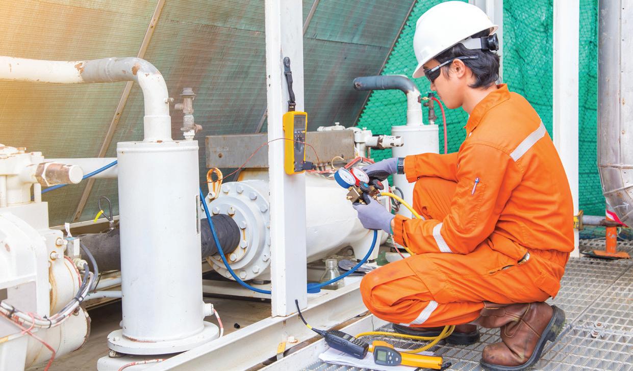
major items of equipment and the friction losses in the interconnection pipework. The sizing of pipework is important because losses increase as pipe size decreases. For this reason, it is proposed to limit flow velocity in pipework to 2 to 3 m/sec. The shape of the system curve will follow a square law for the origin
• Open loop systems – In such systems, the existence of static head is likely and the shape of the system will be somewhat different. Static head will exist at zero flow, while friction losses will increase as flow increases. It is helpful in the pump selection process to know the estimated static head. Again, pipe size is important and should be selected to minimise friction losses within reasonable cost limits
Determining the nominal (predominant) pump duty
Ideally, the pump supplier should be provided with an updated estimate of the nominal duty that the pumping equipment should have to satisfy. This should include:
• The revised estimated system curve
• Any overload or partial loads to be accommodated (preferably in a load profile)
• Any mechanical/electrical conditions or constraints imposed by the consultant specification
• Any special conditions for electric motors or drives should be specified. MEPS compliant motors are available in Australia and can be fitted to long-coupled units relatively easily. Motors fitted to imported close coupled pumps should also be checked for MEPS compliance
This should result in a much more accurate proposal for pumping equipment and allow for pump selection close to best efficiency point (BEP) in all operating conditions.
The pump supplier should also be notified of any changes in major equipment in the HVAC circuit or pipe runs that might affect friction losses that occur during the construction phase. This will help inform if any changes to the pump configuration are required to achieve a satisfactory pump and system match.
The operating point of a pump is determined where the pump curve crosses the system curve. The pump produces
only enough energy to overcome the system resistance generated and the actual flow and head are a result of this balance. The operating point is important for two reasons:
• It should be as close as possible to the pump’s BEP to minimise power consumption
• All operating points (including partial and overload conditions) should be within the POR to minimise unstable operating conditions which may affect the operating life of critical components
As a guideline, the POR might be for flow conditions from 75 to 110 per cent of BEP flow. The use of variable speed drives to more accurately achieve a pump and system match at the commissioning stage is not a preferred solution unless partial and overload conditions fall outside the preferred operating range.
Understanding pump performance curves and selection data
Most pump manufacturers provide pump performance curves or other data that will indicate the flow (Q), head (H), power absorbed (P) and pump efficiency at various impeller diameters and speeds. However, as most standard pumps are mass produced, the pump performance is subject to tolerances, as manufacturing variances are inevitable. Most curves will also provide information on the net positive suction head required (NPSHR) demanded by the pump to operate satisfactorily, although in most cases this is not a major issue in HVAC applications.
The H-Q curve for a pump is really an “energy versus flow” curve. The energy consists of kinetic energy and potential energy which the pump imparts to the fluid as it leaves the pump casing. This energy (normally expressed in metres head) will allow the pump to overcome the total system head generated at the duty point (also expressed in metres head).
Published pump curves are still used extensively in pump selection procedures, although many of the major pump suppliers can also provide computer selection programs to assist in the pump and system matching procedure.

Special care needs to be taken to understand the level of confidence that users can place in the accuracy of the pump performance data. Published pump performance curves are generally based on manufacturers test data performed to a nominated standard. In Australia, the current test standard is AS 2417 – 2001. This is directly equivalent to ISO 9906-1999. Most published pump curves nominate they are valid for mass produced pumps and claim Annex A tolerances.
However, it is unlikely any contract pump will have been subjected to a performance test, unless the customer calls for this to be undertaken. This is not common in the HVAC sector. As a result, the reliability of data in the published curve is only verifiable if the test code is clearly nominated and the tolerances can be assessed.
Any test data will relate to a specific pump configuration being tested and in most cases the pump will be set up in the standard material configuration. Until recently, the standard material configuration for larger end suction pumps was:
Casing: Cast Iron
Impeller: Gun Metal or ZF Bronze Shaft: Stainless Steel (SS416 or SS431)
However, in recent years some suppliers have chosen to supply cast SS impellers and this sometimes has an impact on the seal ring clearances, which results in a de-rate of pump efficiency.
In summary, the accuracy of the pump curve should be assessed based on the limitations that must be clearly defined on the curve. Computer generated curves from manufacturers selection programs should also have the limitations on their validity specified in the event of any potential dispute on performance when the pump is commissioned on-site.
Flow variation/control strategies
Many HVAC systems require a constant flow for most of the operating period. The control system is relatively simple and often the control parameter is “temperature”. In such cases an accurate pump and system match will allow for stable operation at a duty near to BEP without speed control.
However, more sophisticated systems result in more complex operating conditions and variation is more effectively managed by speed control to reduce energy consumption at partial flow conditions.
It is helpful to pump suppliers if system load profiles and control system strategies can be made clear at the time the equipment is ordered, as retrofitting more complex equipment can often result in high additional equipment and installation costs. Guidelines for the effective use of variable speed drives (VSDs) should be outlined in the new code.
Pump performance testing and pump site commissioning procedures
Depending on the anticipated hours of operation and the size of the drive, consideration should be given to performance testing of pumpsets prior to installation at site. This will provide a verifiable basis for actual pump performance and allow for more effective problem solving at the site commissioning phase. While AS 2417-2001 is still current, PIA has made a submission to Standards Australia to adopt the
latest ISO 9906-2012 as the applicable standard for Australia. It is expected this will be adopted early this year, resulting in AS 2417-2001 being superseded by AS ISO 9906:2018.
While there are other testing codes used in other industry sectors, the new standard is adequate for the HVAC sector if correctly applied.
At this stage the recommended tolerances for pump testing should be as follows:
• Pumps tested to AS 2417:2001 – Grade 2 – Use Annex A tolerances
• Pumps tested to AS/ISO 9906:2018 – Grade 3 – Use 3B tolerances
Site commissioning of pumps in the HVAC sector should be undertaken by qualified personnel. This is a very important stage in the lifecycle of pump equipment and very often the only time when it is possible to determine if the pump duty provided to the pump supplier was correctly assessed.
Temporary or permanent instrumentation may be used to measure pump performance and assess both pump power absorbed and pump efficiency at the operating point. This initial site testing provides baseline data for any corrective action to be undertaken to optimise performance and subsequent assessment of any drop off in pump performance over time.
It may not be unusual to find that the site operating point is not an exact match for the duty nominated for the pump. There are several reasons for this and a careful investigation needs to be conducted to determine the causes for any deviation. At this point, an actual pump test curve is very useful, as it should have been undertaken under specified conditions that may not be reproduced on-site.
This is also an ideal time to undertake an energy audit of the equipment. Again, this needs to be undertaken by a qualified professional.
Energy conservation is becoming a global issue and measures that encourage a long-term approach to pump and system design are likely to achieve a good outcome if correctly implemented.
A systems approach to HVAC
A “systems approach” has the capacity to yield significant energy savings within HVAC installations, providing the exchange of information between all parties involved is comprehensive and efficient.
The situation in Australia lends itself to the adoption of European guidelines for circulators and this has been accepted by Energy Australia in its recommendations to ABCB. However, it is possibly too early to adopt the Extended Product approach which is currently being adopted in Europe and in the short term a MEPS recommendation for ISO 2858 and EN 733 pump ranges may be a simpler and easier methodology to adopt.
It would be logical to also adopt the existing MEPS for electric motors used in HVAC applications as this is already applicable to suppliers of electric motors in Australia.
As technology develops, there should be opportunities for further upgrading of pumping equipment specifications to yield additional energy reduction over time.
The NCC 2019 public consultation draft can be viewed at www.abcb.gov.au/Consultation/Public-Comment-Draft/NCC-2019-Public-Comment-Draft. The consultation period for proposed changes is now open and the ABCB is seeking feedback until 13 April 2018. Final changes are expected to be released in February 2019, and come into effect from 1 May 2019.

CONSISTENT AUTOMATION
Electric actuators for hydraulic steel structures
Reliable, powerful, robust.
For several decades, AUMA actuators have proved their reliability in automating sluice gates, butterfly valves and gates in weirs, fish ladders, locks, and hydropower plants.
AUMA’s comprehensive portfolio covers torques ranging from 10 Nm to 675,000 Nm offering homogeneous automation schemes throughout the plant: from simple OPEN-CLOSE applications to level control using an integral PID controller.

Assessing opportunities for high temperature heat pumps in the food industry

With the price of gas rapidly rising over the past two years and the cost of renewables dropping, food manufacturers are looking for opportunities to improve process efficiency and keep the cost of operation down. A report from the Australian Alliance for Energy Productivity (A2EP) has identified a number of key market drivers — including costs and environmental benefits — that are creating opportunities for high temperature heat pumps in food manufacturing.
The report identified several key market drivers that are creating opportunities for natural refrigerantbased (NatRef) heat pumps in the Australian food manufacturing sector, the most significant being the rapidly increasing price of gas in Australia.
The report, High Temperature Heat Pumps for the Australian Food Industry: Opportunities Assessment, is part of a pre-feasibility study by A2EP to define the likely feasibility and range of applications for high temperature heat pumps in the food industry, with a focus on delivering useful heat at 66°C150°C. It is the continuation of a wider project investigating opportunities for innovation in technology/business models that could transform energy productivity in the food value chain. One key transformative change that was identified was the electrification of food processing, displacing fossil-fuel fired boilers and steam systems. Heat pumps are a central technology required for this transition to recover heat from waste streams to boost temperatures, displace steam, and in some cases simultaneously provide process cooling.
Developments in heat pump technology
The past decade has seen high temperature industrial heat pump technology develop rapidly and they are now able to deliver temperatures over 80°C, with cascaded or multi-stage heat pumps now able to reach temperatures up to 140-150°C. The range of applications has also been greatly extended. As these pumps are more efficient when operating across small temperature differences (about two to four per cent), systems using multiple heat pumps in series can achieve large efficiency improvements, allowing them to operate across larger overall temperature differences, however such systems are more complex and expensive.
Other heat pump technology development occurring in Japan includes:
• Eco-Cute heat pumps which use CO2 refrigerants for hot water and hot air supply. These packaged pumps can produce hot water up to 90°C with a heating capacity of up to 72kW
• CO2 heats pumps able to generate hot air to 100°C and a heating capacity to 110kW
• Heating and cooling of circulating water and steam generation using ‘Reverse Rankine’ cycle
• Industrial heat pumps that are capable of providing steam at 120-160°C using cascading or multi-stage systems
These improvements in technology and economies of scale of production of packaged units mean heat pumps are now widely used in many industrial processes, including food manufacturing. While these pumps are now common in Japan, South Korea, and to a lesser extent in Europe to supply heat at up to 95°C, there are far fewer industrial installations in Australia that are able to deliver temperatures over 65°C.
Application type Features
Dryers
Capture sensible and latent heat from exhaust streams
Food washing Capture sensible and latent heat (water vapour) from exhaust streams
Water heating for process cleaning
Capture waste heat from process or refrigeration (or air) compressors
Pasteurisation Can be heating and/ or cooling role
Combined process heating and cooling
Ideal applications use the condenser for heating and evaporator for cooling simultaneously
Typical heat pump applications
Typical industries
Milk, pasta, noodles, etc
Potatoes, vegetables, fruit
All food
Milk, juices, etc
An example is bread – product cooling and proving
Opportunities for heat pumps in the food industry
While there is a significant capital cost for high temperature heat pumps, the development of packaged ‘Eco-Cute’ units in Japan provides relatively economical volume manufactured units for heating water and air to 90°C.
The food industry is an energy intensive industry, consuming around 165PJ of energy — up seven per cent in 2016. Coupled with the rapidly rising price of natural gas, and with potentially limited gas available in the next five years, the economics of high temperature heat pumps is improving and gaining them more interest from the food industry than in the past. The report found that as heat pumps effectively use electricity to harness heat from waste heat streams or the environment at efficiencies of over 300 per cent, they can cost effectively displace gas when gas prices are high. This displacement is also aided by the rapidly falling cost of renewable energy as solar PV can be used to power heat pumps.
The report found value derived from using high temperature heat pumps may include four types of energy productivity benefits:
• Direct energy savings from the coefficient of performance (COP) of heat pumps of three or more (and where simultaneous heating and cooling is possible, this can double). A generalised comparison of the cost of generating heat with heat pumps indicates that heat pumps may generate heat with up to 50°C+ temperature lift at say $10/ GJ (based on $160/MWh power); significantly lower than a typical boiler and steam system using natural gas – at $12/GJ gas cost, heat delivered to process would typically cost over $15/GJ from a steam system (>$25/GJ for an inefficient system)
• The recovery of sensible and in some cases also latent heat, which would otherwise be wasted
• Use of heat pumps as stepping stones towards complete replacement of boilers and steam systems, generating potentially much greater savings, where existing systems have low efficiency
• Additional energy productivity benefits including enabling increased plant throughput, better heating control leading to product quality improvements, and greater reliability than steam systems
While it is difficult to put a meaningful number or range on the potential economical scale of benefits as it is application and site specific, the report found that it appears that there will be many heat pump solutions that pay back within six years (delivering over 15 per cent per annum internal rate of return)
Heat pumps are used in food drying processes, including pasta and noodles
just based on direct energy benefits. Where these installations allow retirement of boilers and steam systems, or where the heat pump fulfils a cooling and heating duty simultaneously the systems could pay back in less than three years. Given these rates of return, there is potential for well-designed financing mechanisms to provide low upfront cost, cash flowpositive finance packages for heat pumps.
Barriers to implementation
While there are now greater opportunities and incentive to implement high temperature heat pumps, the report found there are also still significant barriers to implementation in Australia which explains the small number of installations to date.
Some current barriers for implementation in the food industry include:
• Historically cheap coal and gas prices, which have supported the continuation of central, steam-based heat supply systems and under-investment in end use efficiency improvement
• Lack of business knowledge of the application of this technology as there are almost no local examples and limited local supplier expertise
• Limited incentives to implement the technology
• There is skill required to optimally implement high temperature heat pumps (other than in applications that just directly replace a heating source) including using ‘pinch’ thermodynamic analysis, and determining how to extract the greatest total business benefit. This expertise is not widespread in the Australian market
These barriers have been overcome in Japan and South Korea through government support including information provision, technical support incentives, and investment incentives.
Taking hold of new opportunities
Despite these barriers the opportunities for energy cost savings will continue to build interest in high temperature heat pump applications, especially as gas prices continue to rise and gas supplies deplete, and there is need to move to low carbon energy solutions. For pump suppliers there lies an opportunity to take advantage of the potential of this growing market by gaining greater access to international technology and investing in training to build expertise and experience to fill the current knowledge gap in the Australian market. There is particular opportunity for those in the refrigeration industry as they have the skill needed to rapidly learn about heat pumps for heating duties.

Better aeration system for food process
Hydro Innovations is keen to introduce the Venturi-Aeration aerators to Australia after the success food processors have had with the products in the US and Europe. VenturiAerators are used in conjunction with Gorman-Rupp pumps and can be mounted on the banks of basins and lagoons instead of needing to be installed in them.
Ashort case study is available from Hydro Innovations that describes the conversion of an aeration system at a soup production facility which resulted in operating cost savings of >$112,000/year and increases in total EQ tank performance to produce a clearer effluent, controlling odours, settling solids, cooling the water and hydrolysing fats,
oils and greases (FOG), causing them to float for better removal efficiency.
The existing system was to add dissolved oxygen to mix and equalise the contents in the EQ tank with submerged aerators. These submerged aerators were supposed to add dissolved oxygen (DO) which would cause fats, oils and grease (FOG) to float so they would not be discharged with the plant’s effluent
into the POTW. Secondly, they were to provide cooling of the influent process wash-down water (~40 C).
Ragazzini Rotho Peristaltic Pumps are at the cutting edge of “Hose Pump” design and have the features to make pumping easier They consist of an elastomeric tube that is squeezed along its length by rollers that push the fluid contained within
Advantages:
No seals
Easy hose changes
Ear ly leak detection
No messy lubricants
Flows 0.2 to 180,000 l/h
Run dr y without damage
F Food Grade Hoses available


These aerators had been in operation for several years and were not achieving the desired conditioning objectives. Further, whenever one of the submersible pumps plugged or failed, the facility had to rent a crane to remove the pump for repairs and then had to use the crane for removal, repair and to reinstall the repaired pump at additional costs on each occurrence. A failure of one or more of the submerged pumps was occurring at least once if not twice a year, adding to systems operating costs just for crane rental.
The facility was looking for a more viable aeration, mixing and equalisation solution to keep them in compliance.
The facility environmental engineer decided to replace his existing aerators with a Model VA-1400 venturi aerator and a T8 Gorman-Rupp pump. The venturi aerator was designed to handle 82 L/s. This allows the contents of the EQ tank to be recirculated four times during a 24-hour period achieving greater oxygen transfer and better mixing and equalisation. With better circulation and cooling in the EQ tank, the FOG is floated for separation and treatment, and is not being discharged with the effluent to the local wastewater treatment plant, reducing surcharges.
The plant was able to achieve a $6,000 P/A energy cost reduction, an $89,000 annual reduction in chemical costs, and a $12,000 annual reduction in non-compliance charges, along with maintenance cost reductions.
The facility environmental manager now has a system that allows him to achieve his discharge permit parameters and he has less concern over maintenance issues and costs.
The complete case study is available from Hydro Innovations.
…Gorman-Rupp Pumps – no worries…

Air operated diaphragm pumps from Sweden
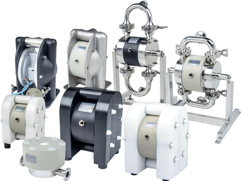




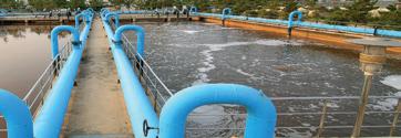


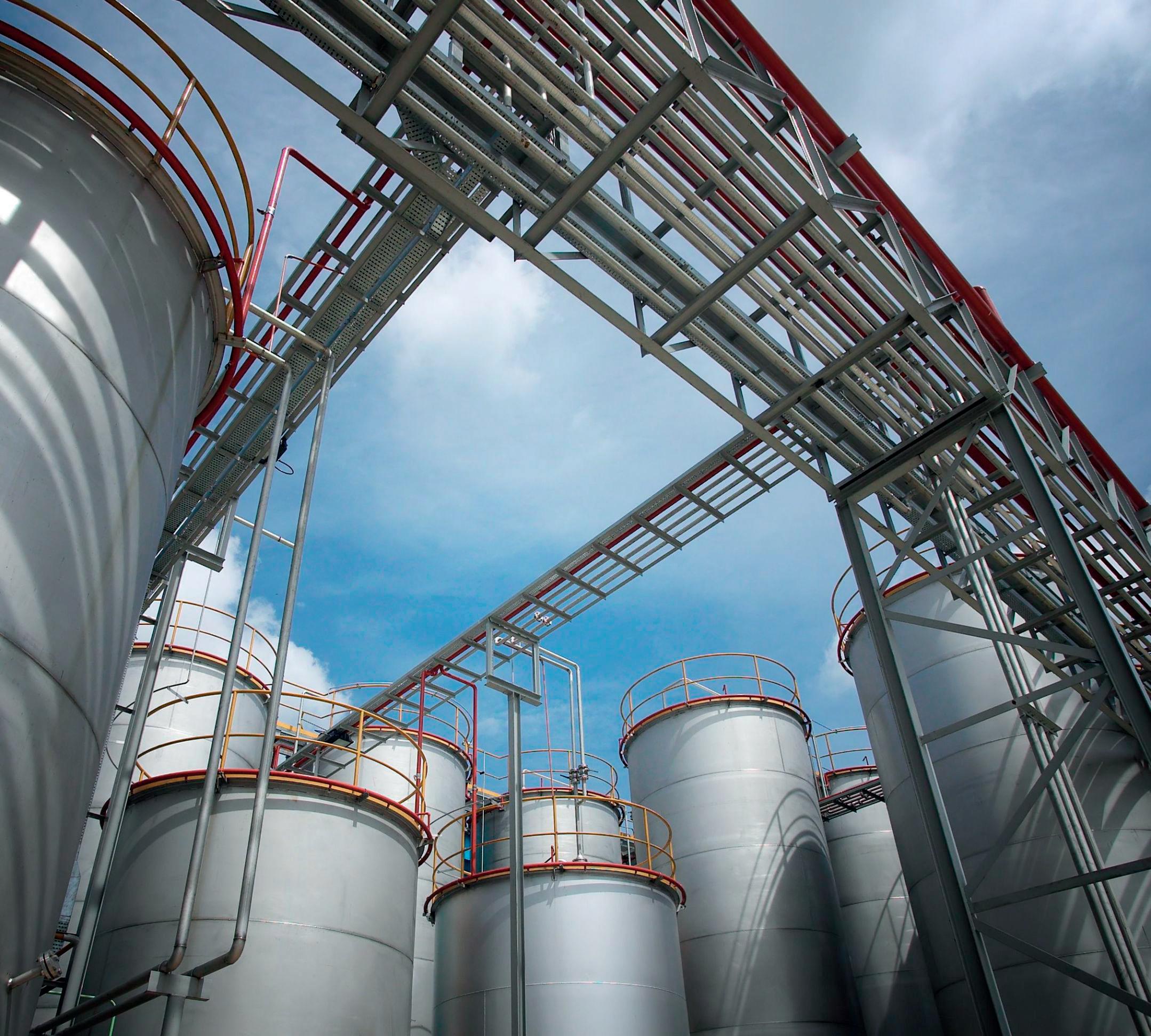

FLOW METERS IN PIPING SYSTEMS
by Ray Hardee, P.E., Chief Engineer, Engineered SoftwareKnowing the flow rate within a fluid piping system is one of the most useful measurements in understanding system operations. The equipment used to measure flow rates are typically maintained and calibrated by the plant instrumentation and control groups. Facility flow meters are typically used to monitor custody transfer or as the primary elements of flow control circuit.
Meters used for custody transfer are designed to provide accurate and repeatable values for flow rates when products are being sold or purchased. These types of flow meters often measure a positive volume when dealing with small quantiles, or the volume can be totalised over a time when measuring large quantiles. The value of flow rate used for custody transfer also helps operate and maintain other plant equipment.
When the design objective of a piping system is to establish a set flow rate of a process fluid, a flow control loop is used (Figure 1). The following describes how the control elements of the system work together to achieve the proper flow rate. The flow meter measures a value that is a function of the flow rate through the meter. The meter then transmits a measured value to the controller. At the controller, the desired value for the flow rate is entered. The controller then compares the measured value from the meter to the set value and sends an output signal to the actuator. The actuator then adjusts the final element (a control valve or a variable frequency drive) to eliminate the excess energy needed to balance the flow rate to the set value. The controller provides the operator with actual measured flow rate.
The initial cost of the equipment, and the effort needed to calibrate and maintain these types of flow meters can be cost prohibitive for wide used within a plant. In this article, we will look at ways to measure the flow rate within piping system without the expense of the custody transfer meters or the complexity of a flow control loop.
Types of flow meters
Flow meters fall in two general categories: those that determine the flow based on the pressure drop across the meter, and those that measure a value that has a linear relationship to the flow rate through the meter.
Differential pressure flow meters consist of a flow restriction within the flow stream that causes a differential pressure across the meter. Based on the Bernoulli principal, the flow rate through
the meter is a function of the square root of the differential pressure across the flow restriction. The meter takes the square root of the differential pressure and displays the results on a calibrated scale showing the flow rate.
A linear flow meter consists of a measured signal that is directly related to the flow rate through the meter.
Differential pressure meters
The most common flow meter is a differential pressure meter consisting of an orifice with a concentric round hole machined to a specific value. The orifice provides the restriction to flow, pressure taps located on the upstream and downstream side of the restriction provide the necessary differential pressure.
When the process fluid passes from the upstream pipeline into the meter the restriction in the orifice causes an increase in the velocity of the fluid as it passes through the restriction. Within the restriction some of the pressure head is converted to velocity head. After passing through the restriction the flow slows down, resulting in conversation of velocity head back to pressure head, the hole in the orifice plate the velocity of the process fluid increases. The increase in the process fluid within the orifice plate causes some of the pressure head to velocity head. The square root of the differential pressure across the orifice plate is a function of the flow rate through the orifice.
The reason for the wide acceptance of orifice plates is based on their simple operation, can be incorporated using readily available instruments to read differential pressures, and the ability to be easily manufactured to meet design flow requirements. In North America, orifices can be sized using standards developed by the American Society of Mechanical Engineers standard (ASMEMFC-3M), or the American Petroleum Institute standard 2530. The standard provides requirements for the location of the differential pressure taps and the method for sizing the diameter of the hold in the orifice plate.
Since the operation and accuracy of the orifice plate is well understood, and the orifice plate and pressure taps can be located at flange faces within a piping system, this style of flow meter can be locally fabricated and inserted in the pipeline when needed.
An annubar is another type of meter that can be inserted into a pipeline for accurate measurement of the flow rate. The meter works by measuring the difference between the total fluid pressure and the static pressure over a large cross-sectional area of the pipeline. The design of the annubar allows it to be easily inserted into the flow stream when needed. This type of meter is a manufacturers product designed and tested prior to installation.
Linear meters
Next, we will look at meters where the measured value in the meter is a direct function of the flow rate through the meter.
A vortex meter uses a specially designed bar inserted into the flow stream to create fluid vortexes within the flow stream. The meter counts the number of vortexes created over time, which is a linear function of the flow rate through the meter. Vortex meters are available from a variety of instrument manufacturers and as a total unit. The bar inserted into the flow stream causes a loss in pressure, but it is much less than an orifice plate.
Ultrasonic flow meters measure the frequency change of a sound wave travelling through the process fluid. Ultrasonic flow meters can be based on the time of flight of the sound wave through the process fluid, or the change in frequency caused by the doppler effect.
In a time of flight flow meter, a transducer projects a sound wave into the pipe, the sound wave travels through the process fluid and is reflected off the opposite pipe wall and travels to a second transducer located downstream of the first. A second sound wave leaves the downstream transducer, making the trip in the opposite direction. Knowing the distance and the time taken to
make the round trip provides the meter with the speed of the fluid in the pipe, providing a linear relationship with the flow rate through the pipe.
In a doppler type meter a transducer sends a sound wave at a given frequency into the flow stream. When the sound wave is reflected off a small practical or bubble within the flow stream, frequency of the reflected sound wave changes. Using the doppler principal, the meter measures the change in frequency of the sound wave to determine the velocity of the process fluid. The fluid velocity provides a linear relationship between the fluid velocity and the flow rate.
Measuring the flow in a pipeline
Installing a flow meter within a piping system is an expensive process, as such most flow meters are used for custody transfer applications or when the flow rate with a process is required to meet the system design requirements.
As we have discussed in previous articles, knowing the flow rate through a pump, pipeline, heater, or control valve can be useful in determining if that equipment is operating properly or needs maintenance. All the examples presented in this article can be installed for use within the piping
ABOUT THE AUTHOR
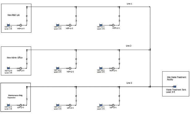
system when needed. For example, an orifice can be installed between existing flange faces connecting pipe segments. Annubar’s can be quickly inserted into a pipeline when the plant is shut down and will provide a flow rate when needed. A vortex meter must be installed in a pipeline, but the calibration and maintenance of this type of meter is less than a typical differential pressure meter.
Finally, portable ultrasonic flow meters can be installed to the outside of a pipe without affecting system operation. The meter can be affixed to the pipe, the flow rate measurement can be taken when needed and then it can be moved to a different location when needed.
Each of these types of flow meter will provide excellent results when used properly, to help gain a clear picture of the operation of the total piping system.
Ray T Hardee, PE, is the Chief Engineer and a principle founder of Engineered Software Inc., creators of PIPE-FLO® and PUMP-FLO® software. The PIPE-FLO product line helps some of the largest companies across a variety of industries find hidden profit in the design and operation of their fluid piping systems through simulation software, modelling services, and training opportunities. Hardee is a member of the Hydraulics Institute, ASME Energy Assessment for Pumping Systems standards committee and ISO Pumping System Energy Assessment committee. Hardee’s publications include Piping System Fundamentals and contributions to HI’s Pump Life Cycle Cost and Optimizing Piping Systems. He can be reached at SimGuyRay@eng-software.com

agriculture and irrigation. Reliable, high performance, quality materials, and the widespread Lowara support network make these pumps an ideal selection for your water supply requirements.
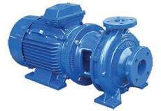



The pump industry relies on expertise from a large and varied range of specialists, from experts in particular pump types to those with an intimate understanding of pump reliability; and from researchers who delve into the particulars of pump curves to experts in pump efficiency. To draw upon the wealth of expert knowledge the Australian pump industry has to offer, Pump Industry has established a panel of experts to answer all your pumping questions.
This edition of Ask an expert will look at why progressive cavity pumps are vital for the wastewater and sludge treatment industry.

Q: Should correct equipment selection really be an important issue for these industries?
A: While process optimisation, economies of scale and deregulation all play key parts in increasing energy generation in the water industry, it is vital not to overlook the importance of correct equipment selection. Pumps, in particular, are essential to the water sector’s continued success and selecting the right pump for the job will give the optimum return on investment.
Minimising the energy use of equipment is extremely desirable. Progressive cavity (PC) pumps compare well in this respect to other pump technologies, because of their ability to maintain flow – even with varying pressures and variable sludge viscosities. This specifically comes into play when feeding heat exchangers to ensure the most efficient heat transfer of the sludge.
When selecting the right equipment for your application, tailor-made packages can improve reliability, performance and cost efficiency. PC pumps can be integrated with complementary equipment, such as special live bottom silos, boundary layer injection systems, back-mixing technology and intelligent control systems.
Q: What is distinct about progressive cavity (PC) pumps for sludge cake?
A: Sewage treatment processes remove the water from raw sewage to thicken the sludge before dewatering to a dry solids content (ds%) of between 18–35 per cent.
PC pumps are adept at transferring this ds% sludge with lower energy demands than other pump types. This reduces the system’s pressure rating, enabling de-rating of pipework and valves.
Sludge cake pumps are large so it is vital that they are not only efficient in use, but also have accessible wearing parts for ease of maintenance when required. PC sludge pumps can competently provide both.
There are numerous case study examples where PC pumps for sludge cake shine over competitors. In one instance, after two years the pumps required no maintenance interventions, delivering a hat trick of cost reductions: lower sludge disposal costs, lower energy use and reduced maintenance costs. Furthermore, the pumps offered minimal pulsation pumping, which generated lower pressure in the pipework. In another instance, PC pumps were specifically chosen since they can handle low to high viscosity products, sludge with 45 per cent ds and are not hindered by solid particles. They also offered good discharge pressure capabilities that enabled long distance pumping.

Peter Vila, Managing Director of SEEPEX Australia, is a progressive cavity pump expert. He has been involved with pumps for over 35 years. Peter spent the first five years repairing pumps and the following 30 years in technical sales, 15 of which have been with SEEPEX progressive cavity pumps.
For more information on progressive cavity pumps, please contact SEEPEX Australia on (02) 4355 4500 or at info.au@seepex.com
Retired engineer with a knowledge of pumps.
The position is varied and interesting. Excellent conditions in a friendly environment. Ring Link Pumps on 03 9391 9600 WANTED
Retired engineer needed for part-time customer relations work. A good knowledge of pumps and a pleasant personality required.
The company is a family owned business based in Williamstown, Victoria. Best suited to someone living in the western suburbs of Melbourne.
SELECTING & APPLYING POSITIVE DISPLACEMENT PUMPS
PART 4

The PIA’s Australian Pump Technical Handbook is a cornerstone text for the Australian pump industry and, in our opinion, a must have for anyone who deals with pumps on a regular basis. In this ongoing series, we feature abridged chapters from the classic book to showcase the various areas covered and to reacquaint readers with the technical aspects of pumps. In this issue, we continue our detailed look at selecting and applying different types of positive displacement pumps.
Lobe pumps
Lobe pumps operate similar to external gears pumps in that fluid flows around the interior of the casing. However, unlike external gear pumps, the lobes don’t make contact. Lobe contact is prevented by external timing gears located in the gearbox, and since the bearings are out of the pumped liquid, pressure is limited by bearing location and shaft deflection. A shaft seal is required for each shaft which are usually special short designs to minimise shaft length and overhang.
Lobe pumps are manufactured with a variety of lobe operations including single, bi-wing, tri-lobe and multi-lobe.
Rotary lobe pumps range from industrial designs to sanitary designs. The sanitary designs break down further depending on the service and specific sanitary requirements, including 3-A, EHEDG and USDA.
Characteristics of lobe pumps
Rotary lobe pumps are non-contacting and have large pumping chambers, allowing them to handle large solids such as cherries or olives without damage. They are also used to handle slurries, pastes and a wide variety of other liquids. If wetted, they offer self-priming performance. A gentle pumping action minimises product degradation. They also offer reversible flows and can operate dry for long periods
of time. Flow is relatively independent of changes in process pressure so output is constant and continuous.
Since the lobes don’t make contact and clearances are not as close as in other positive displacement pumps, internal leakage is increased and volumetric efficiency decreased when pumping low viscosity liquids. High-viscosity liquids require considerably reduced speeds to achieve satisfactory performance. Reductions of 25 per cent of rated speed and lower are common with high-viscosity liquids.
Cleaning is important when the product cannot remain in the pump for sanitary reasons or when products of different colours or properties are batched. Lobe pumps are easily cleaned by circulating a cleaning fluid through them, a process generally described as “clean in place” (CIP).
Lobe pumps have a number of advantages, including:
• Will pass medium sized soft solids with minimal damage to the solids, which is especially useful with fluids containing food
• No metal-to-metal contact between rotors and casings
• Very good CIP/sterilisation in place (SIP) capabilities
• Non-pulsating discharge
• Bi-directional flow
There are, however, also a number of disadvantages, including:
• Requires external timing gears and two shaft seals
• Reduced suction lift with thin liquids
• Reduced capacity as pressure increases (due to slip through rotor and casing clearances)
• Abrasive solids can cause high wear rates, however this can be reduced with optional materials such as rubber or urethane coated rotors and end covers
Common applications for lobe pumps
Lobe pumps are frequently used in food applications because they can handle solids without damaging the pump. They can pump larger particle sizes than other positive displacement pumps.
They are also commonly used for other industries deemed to be ‘clean industries’ such as:
• Beverage
• Pharmaceutical
• Personal care products
Lobe pumps may also be used in other industrial applications listed below:
• Polymers
• Paper coatings
• Soaps and surfactants
• Paints and dyes
• Rubber and adhesives
Specific care needs to be taken in these applications and it is best to seek manufacturer or supplier recommendation.
Circumferential piston pumps
Circumferential piston pumps are similar to lobe pumps in both design and application. However, the rotor and casing design is very different. Circumferential piston pump rotors are arranged as arc-shaped “pistons” (rotor wings) that are cantilevered from the rotor hub and travel in annularshaped cylinders formed between the outer casing and the inner cantilevered stationary pillar. The resulting long circumferential sealing path between the rotor and casing reduces slippage on low viscosity products and produces a smooth flow of product with minimal pulses.
The rotors are made of a special non-galling stainless steel alloy which allows very close clearances to further improve efficiency on low viscosity products.
Characteristics of circumferential piston pumps
Circumferential piston pumps have very similar characteristics to lobe pumps. However, the long circumferential sealing path reduces slip and improves volumetric efficiency on low viscosity liquids at medium to high pressures. Shearing of shear sensitive liquids is also lower, handling of slurries is better and NPSHR is usually lower.
Circumferential piston pumps are good for handling slurries because if the pump stops and the slurry settles to the bottom of the casing, when restarted the rotor wings will act like a shovel and scoop the settled slurry out of the discharge port.
The closer clearances, made possible by the non-galling alloy rotors and the long leakage paths inherent in the rotor design, improve volumetric efficiency on low viscosity liquids compared to typical lobe pumps.
Common applications for circumferential piston pumps
Circumferential piston pumps can be used in the same applications as lobe pumps, with selection preference often being decided upon standardisation and/or experience with existing plants in the user’s plant.

Lobe and circumferential piston pumps are commonly used in the pharmaceutical industry.
Twin screw pumps
Twin screw pumps use a pair of specially profiled, opposite rotation screws that mesh in an interchangeable casing liner. On most designs, small but positive clearance between the screws is maintained by external timing gears. Most twin screw pumps are double suction designs which are inherently in hydraulic balance in the axial direction due to their symmetry. Most designs use mechanical shaft seals and external roller bearings, although some use pumped liquid lubricated bearing brushes which reduce the number of seals required.
Each wrap of screw thread forms a cavity that moves axially from suction to discharge. The wrap, or cavity, acts as a pressure stage. Low pressure pumps have only one or two wraps (stages), while high pressure pumps may have 12 or more wraps. The staging effect allows each stage to handle a moderate pressure rise, resulting in low stress levels within the pump even at high pressure operation.
Characteristics of twin screw pumps
Designs have external timing gears and bearings to keep the screws from contacting each other or their casing bores. These pumps can successfully handle low viscosity, low lubricity, liquids — including liquids with light abrasives — in addition to more viscous fluids. They can also run dry without damage and are self-priming.
Twin screw pumps are usually available in low (16 bar), medium (80 bar) and high bar (200 bar) ranges with capacities up to approximately 5000 m3/hr. Efficiencies are usually very high and noise levels low.
Common applications of twin screw pumps
Twin screw pumps are generally used on hydrocarbons ranging from crude oil to bitumens and lubricating oils, vegetable oils and water.
Applications include:
• Tanker unloading
• Fluid transfer
• Fuel feed
• Hydraulic power
• Heavy machinery lube oil supply
• Multi-phase oil and gas flow in oil well production pumping Industries include oil and gas refineries, shipbuilding, power generation and fuel oil systems, and chemical manufacturing and supply.

Triple screw pumps
Triple screw pumps have one driven screw and two idler screws running in three precision bores in the housing or liner. The power rotor drives the rolling idler rotors which are separated by a thin film of pumped liquid. The screw profiles form a seal between the liquid filled cavities that convey the liquid from suction to discharge.
Triple screw designs are usually single suction and are fitted with one seal whereas twin screw pumps usually require four seals; one at each end of the two shafts, although single seal designs with product lubricated bearings can be used if no abrasives are present.
Characteristics of triple screw pumps
Triple screw pumps are suitable for use with non-abrasive, lubricating fluids with low to medium viscosities. They are not suitable for dry running.
Operating speeds can be quite high, with high efficiencies and low noise levels. Flow rates are low to medium (to about 700 m3/hr) with pressures to approximately 300 bar.
Common applications of triple screw pumps
Triple screw pumps are used on many of the same fluids, applications and industries as twin screw pumps, within their smaller capacity range, provided that the fluids are lubricating and non-abrasive.
Further information and detailed diagrams, equations and schematics can be found in the Australian Pump Technical Handbook, available from the PIA website. In the next edition of Pump Industry, we will explore the selection and application of different types of slurry pump.
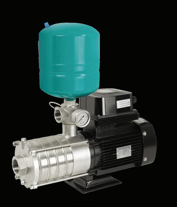


LEADING THE INDUSTRY TOWARDS A SUSTAINABLE FUTURE THROUGH TRAINING & CERTIFICATIONS
IRRIGATION PUMPS
& SYSTEMS - 2 DAYS TRAINING
Irrigation Australia operates Irrigation Training Australia (ITA), a Registered Training Organisation (RTO) providing a range of industry related training courses and workshops that contribute towards nationally accredited qualifications including Cert II, Cert III, Cert IV in Irrigation.
WORKSHOP OVERV IEW
Learn the process of operating and maintaining irrigation pumping systems and be issued with a statement of attainment for the nationally recognised competency
AHCIRG410 Select and Manage Pumping Systems for Irrigation. This workshop is designed for anyone working in the irrigation industry whether in retail or irrigation pump system design including selection & supply, irrigation pump system installation, commissioning, monitoring and operation.
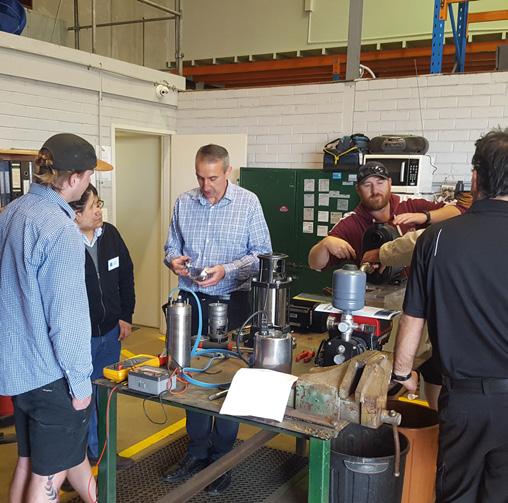
COMPETENCIES
AHCIRG410A | Select and Manage Pumping Systems for Irrigation.
UPCOMING IRRIGATION PUMPS WORKSHOPS:
Scoresby, VIC 27-28 MARCH 2018
Wembley, WA 9-10 APRIL 2018
Townsville, QLD 17-18 APRIL 2018
Mt Gambier, SA 17-18 MAY 2018
LEARNING OUTCOMES
Det ermining system requirements
Types of irrigation systems
Irrigation and pumping system requirements
Hydraulics of irrigation systems including friction calculations
Understanding pump curves
Cavitation and NPSH
Pump selection
Control and protection systems
Installation and commissioning of irrigation pumps
Maintenance and troubleshooting of irrigation pumps
Testing pump performance

RANGE OF INDUSTRY TRAINING:
Centre Pivot Lateral Move (2 days)
Meter Validation and Installation (2 days)
Irrigation Efficiency (2 days) Introduction to Irrigation (2 days)
Cert III in Irrigation
This qualification reflects the skills and knowledge required to become a sales, installation or operations technician within the irrigation industry. It applies to skilled workers who carry out sales, installation and operation job roles in irrigation, servicing horticulture, landscape and agriculture industries. Irrigation Australia offers a tailored blended training program where students complete two units of competency in their own time and then attend the Cert III Training School which is composed of two blocks of either 6 days followed by 2 days follow-up or two blocks of 4 days to gain competency in the remaining 12 units.
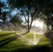
PUMP SCHOOL

The principle of how a positive displacement pump works
Positive displacement pumps are one of the most commonly used pumps in the industry. Here is an example of a Viking positive displacement pump to demonstrate how it works.
Viking’s simple “gear-within-a-gear” principle has only two moving parts. The first part is the positive displacement of the liquid that is accomplished by filling all the spaces completely between the teeth of the rotor and idler gears.
With every revolution of the pump shaft, a certain amount of the liquid enters the pump through the suction port. The liquid then goes on to fill the spaces between the teeth of the rotor and the idler. The crescent on the pump head then separates the flow of the liquid as it effortlessly moves toward the discharge port.
The idler gear, which carries the liquid between its teeth and the inside surface of the crescent is then rotated on the pin which is supported by the pump head.
The rotor gear transports the liquid between its teeth, which travels between the casing and the outside surface of the crescent which is connected to the pump shaft. The four diagram drawings illustrated below show how a positive displacement pump works.
The coloured portion at left indicates the liquid as it enters the suction port area of the casing and the area between the rotor teeth and corresponding concave area between the idler teeth. The two black arrows indicate the pump rotation and progress of the liquid.
This view shows the pump in a completely flooded condition and in the process of discharging the liquid through the discharge port. The rotor and the idler teeth mesh, forming a seal equidistant between the discharge and suction ports, forcing liquid out the discharge port. 1 3
Notice the progress of the liquid through the pump and between the teeth of “gear-withina-gear” principle. Also note how the crescent shape on the head divides the liquid and acts as a seal between the suction and discharge ports.
This illustration shows the pump in a nearly flooded condition just previous to the liquid being forced into the discharge port area. Notice how the gear design of the idler and rotor form locked pockets for the liquid so as to guarantee absolute volume control.


THE HEART OF QUEENSLAND MINING & ENGINEERING






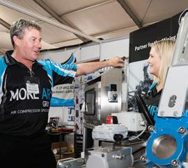


DISCOVER what is POSSIBLE





CONNECT with INSPIRATION



GAIN a competitive EDGE


COME with a problem, LEAVE WITH A SOLUTION


