pumpindustry
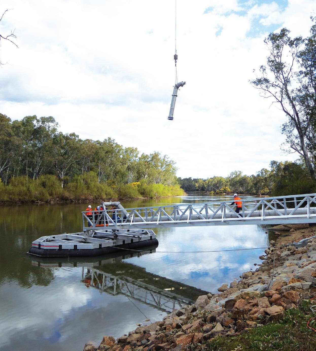
Designing a floating pump station
Australia’s problem with fire pump standard compliance


Australia’s problem with fire pump standard compliance

Don’t risk being non-compliant with the new Queensland Building & Construction Commission regulations. Manufactured to Zetco’s high standards in Italy, our extensive range of WaterMarked valves passes rigorous design and testing processes to ensure that every valve is of premium quality. Ask for Zetco WaterMarked valves at major plumbing retailers. Zetco Valves. Best range. Best quality. Best brand.

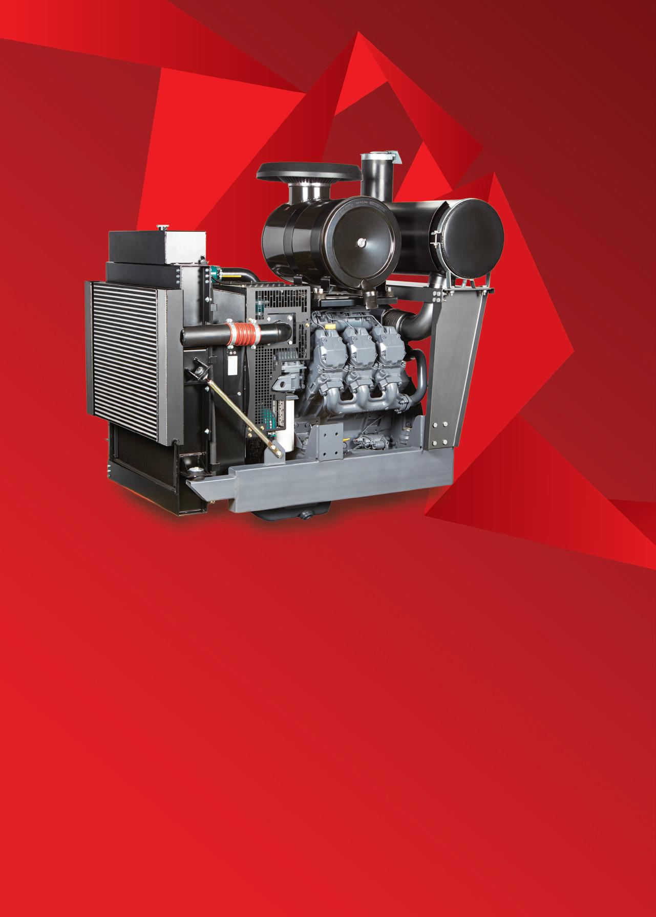
Our No.1 engine solution is now bigger than ever.
DEUTZ Drive is a fully assembled ‘plug and play’ Power Pack package, that’s beautifully designed and can be customised to suit any stationary platform.
The bigger range boasts more horsepower, is easy to assemble and uses less fuel.
Best of all, you can control it from anywhere with remote start and stop.
Proudly Australian, DEUTZ Drive is the preferred pump and irrigation solution.


Pump Industry Australia Incorporated PO Box 55, Stuarts Point NSW 2441 Australia Ph/Fax: (02) 6569 0160 pumpsaustralia@bigpond.com
PIA Executive Council 2019
John Inkster - President Brown Brothers Engineers
James Blannin - Vice President Stevco Pumps & Seals
Kevin Wilson - Treasurer/Secretary Executive Officer
Alan Rowan - Councillor Executive Officer - Publications and Training, Life Member
Ken Kugler Executive Officer - Standards, Life Member
David Alexander - Councillor KSB Australia
Andrew Black - Councillor Envirotech Water Solutions
Mike Bauer - Councillor DynaPumps
Jim Athanas - Councillor Xylem Water Solutions
Hem Prakash - Councillor Davey Water Products
Anant Yuvarajah - Councillor ASC Water Tanks
Hello all and welcome to this edition of Pump Industry Magazine. Autumn is almost a welcome relief to the extremes we have seen over the summer months, from the prolonged devastating drought in NSW, Southern QLD and parts of VIC to 100year floods in Townsville and bushfires in Tasmania; a lot for our emergency services to cope with, let alone those directly affected.
2019 begins with some new Councillors on board who are already active in recruiting new members. By the time this Autumn edition arrives on your desk, we will already have had our first Technical Meeting which was held on the 19th March at Davey Water Products in Scoresby. The presenters were Ashley White and Jamie Dixon, our thanks to Davey Water Products for making their facilities available and for Anant Yuvarajah organising the guest speakers.
Other events in the process of planning include an Installation and Commissioning Course to be held in Brisbane in May alongside a Technical Meeting is planned for May in Brisbane. Technical Meetings are also planned for Adelaide, Perth and Sydney in July, August and October respectively; amongst these there will be some halfday seminars with topics and venues yet to be decided.
I would also like to thank all our Engineering Officers who are back on board for 2019 with Ken Kugler being responsible for Standards, Louise Black for Marketing and Alan Rowan for Publications and Training.
In the Summer edition of Pump Industry Magazine there was an article on complying with Fire Pump Standards which is very timely. PIA has been working closely with the Fire Protection Association Australia (FPAA) to create a checklist to ensure close compliance with the requirements listed in AS 2941:2013 Fixed fire protection installations –Pumpset systems.
I say this is timely as recent events — most notably the Opal Tower saga — highlight shortcomings in the selfregulation and certification processes in the building industry. One would expect that if you purchase an apartment in a high-rise building that the relevant building codes have been met and the apartment is safe to live in; experience tells us this cannot now be taken for granted as not only Opal Tower demonstrates, but also the 86 level Torch
apartments fire in Dubai in 2015, Grenfell Tower fire in 2017 where 72 people were killed, and more recently five levels of the 41-storey Neo200 building in Melbourne.
Thousands of people have been impacted by these fires and it’s just not flammable cladding that comes to mind; there have been serious issues with glass panels, illegal asbestos products and cheap electrical cables. My question here is how well prepared are we as the peak body of the pump industry should events of this nature arise within the fire industry as it is governed by the same set of selfregulation and certification processes that we have in the building sector.
This should be of concern to us all and it is important that all of our members who supply fire systems ensure best practice and comply with the rules and regulations set down in the National Construction Code (NCC) to provide protection for the public in terms of safety; hence the article in the last edition of Pump Industry Magazine. The checklist can be downloaded for free from the PIA website.
Perhaps it is time for there to be a National Register of Certified Pump Suppliers to the fire industry with FPAA approving the certification process; these are my personal thoughts and not necessarily those of the PIA. Until the self-certification processes are monitored more closely by states and government then nothing will change, the issues will remain and there will be a loss of confidence in the likes of the NCC.
Whilst speaking of the NCC, Ken Kugler advises that the preview of the 2019 NCC requirements for air conditioning pumps has moved us into the era of energy efficiency. In March when the new document becomes live, these pumps must comply with European Regulations 522/2012 (circulators) and 547/2012 for larger pumps. PIA will release more details in the future.
Also via another government energy efficiency initiative, the PIA is taking part in discussions regarding the possibility of a MEPS programme for industrial pumps. As it is early days it will be some time before we have an understanding of the direction this may lead.
On behalf of the PIA and all Councillors I wish you all a prosperous 2019 and let’s work towards a reinvigorated PIA.
John Inkster President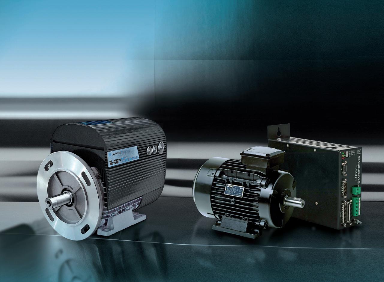


HIGH PERFORMANCE MOTORS SIGNIFICANTLY REDUCE ENERGE COST, SAVE WEIGHT AND SPACE
TWO VERSIONS AVAILABLE
HPI INTEGRAL DRIVE
REDUCTION WEIGHT AND DIMENSIONS HPS STAND
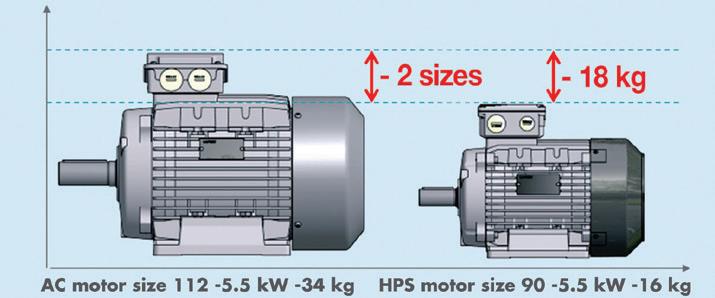

Lafert have merged the permanent magnet motor with the AC induction motor to produce a package that saves weight and space, can be run on most standard drives and is IE4 compliant.
• IE4 compliant and high efficiencies across the speed range
• Space and weight saving of around 50%
• Sensorless motor control that can be driven by most standard drives
• HPS version available from stock


4,706


ABN: 36 426 734 954
PO Box 1763
Preston South VIC 3072
P: (03) 9988 4950
F: (03) 8456 6720
monkeymedia.com.au
info@monkeymedia.com.au pumpindustry.com.au magazine@pumpindustry.com.au
Editor: Lauren Cella
Assistant Editor: Siobhan Day
Business Development Managers: Alastair Bryers, Rima Munafo
Senior Designer :



Following extensive, competitive tender processes, Snowy Hydro has appointed preferred tenderers for the Snowy 2.0 project.
Hydropower engineering and equipment supply company, Voith Hydro, is the preferred electrical and mechanical
tenderer, and is set to deliver the latest hydrogeneration technology in the new power station.
The preferred tenderer for the civil works is Future Generation, a partnership between Australian construction and engineering company, Clough, and global hydropower and tunnelling specialists, Salini Impregilo. Australian company Leed Engineering has also been awarded the contract for exploratory works preconstruction activities.
This marks a significant step towards the commencement of Snowy 2.0. It is hoped that the pumped hydro project, along with the existing Snowy Scheme, will underpin the stability of the energy market as more renewable energy enters the system.
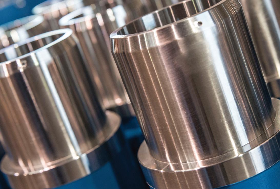
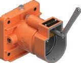

For the past 40 years, AusProof, an original equipment manufacturer (OEM) has grown into a leader in coupler research, development, design, manufacturing and distribution. AusProof have carried their reputation of quality, reliability and innovation through to the newest addition, the PES 60A plug and receptacle range. This PES 60A range is fully certified to AS/NZS1299.


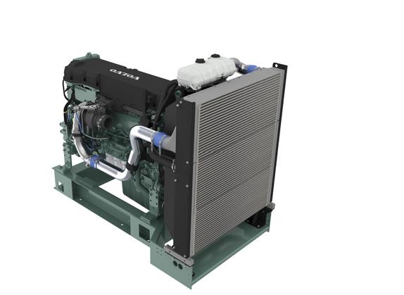
Volvo Penta. Robust, fuel efficient industrial diesel engines that keep running even in the toughest conditions. Easy to install, operate and maintain. A powerful partnership you can trust all the way from the drawing board throughout the operational life of your engine. Competitively priced complete power-pack units ready for delivery Australia wide with a local support team on hand 24/7. To find your nearest dealer visit www.volvopenta.com

Pumps are being used by dam engineers to simulate water events on scaled models of dams to test and refine the designs for large engineering projects on some of South East Queensland’s most important dams.
The Seqwater dam engineers have been working with the University of New South Wales’ Water Research Lab team to evaluate the spillway upgrade options and optimise the designs for the proposed spillway upgrades for Lake Macdonald and Somerset Dams.
Rushing water is sent down scale model replicas of each dam — built of wood, concrete and gravel — to test the hydraulic performance of each design and expose any weaknesses.
Data is collected on flow velocities, areas of turbulence, changes in flow depths and the dissipation of energy, to allow the design of the upgrades to be refined for the full range of design flood events.
“During these tests, we collect velocity, depth and pressure data to assist in the developing the preferred design of each upgrade.
“This is an important validation process — water behaves in a similar at the smaller scale and allows engineers to replicate the performance of the proposed upgrade during extreme floods.”

Seqwater Lead Storage Planning Engineer, Craig Wiltshire, said even though the models were small-scale replicas, they are still quite large.
“The Somerset Dam model was 50 times smaller than the existing dam with model being six metres wide and 16m long.
“A pump was used to discharge large amounts of water into the model to simulate extreme floods and we would adjust the flow of water to create different flood scenarios.” Mr Wiltshire said.


Mr Wiltshire said hydraulic modelling and analysis were critical components in the design of any dam project.
“Modelling provides important insights into different aspects of a dam’s design such as how excess water is safely passed through the dam and into the downstream river channel, where erosion could occur and understand the effects of natural floods.
“For Lake Macdonald and Somerset Dams we have used scaled physical models in the design and investigation of these dam upgrade projects.
“Another option is to use computer simulations to gain design information but sometimes the physical models more accurately show the hydraulic performance than computer modelling, especially in the case of chaotic things like water flow in highly turbulent zones.”
Both Lake Macdonald and Somerset are set to undergo major upgrades in line with Seqwater’s Dam Improvement Program, with each project priced in the hundreds of millions of dollars.

Gippsland Water has awarded a contract to undertake civil works on a new outfall sewer pump station for Sale, Victoria.
Local company GBG Concrete & Construction was awarded the contract and was expected to begin site excavation in February 2019.
Sarah Cumming, Gippsland Water Managing Director, said, “The excavation will enable us to install a storage tank and wet well, which are essential to support the ongoing development and liveability of our region.
“When complete, this important piece of infrastructure will service Sale, Wurruk and Fulham for the next 65 years.”
Ms Cumming said the project had been carefully planned to reflect community feedback.

“We’ve been working with Wellington Shire Council and the community throughout the planning and design phase, and we’re excited to be incorporating a community-led concept for the fencing and planting of the site.”
The new outfall sewer pump
station, expected to be completed in late 2020, is one of three Gippsland Water infrastructure projects being delivered in Sale during 2019, along with a sewer pump station on Raglan Street and a new main at the Sale Water Treatment Plant.


Enquiries: gjc@gjc.com.au
Peekarra Street, Regency Park, SA 5010
Phone: 08 8118 6450 www.gjc.com.au


Australian Potash has announced the final field programs of work have begun in the Definitive Feasibility Study (DFS) of the Lake Wells Sulphate of Potash Project.
The study will include the finalisation of resources and of the environmental monitoring program, which will feed into the Environmental Review Document.
The resource finalisation will include up to three further production wells being developed to depths between 140–170m, as well as three monitoring bores per production well. The bores will be drilled to plot aquifer response during pump testing.
The long-term pump testing of production wells will confirm flow rates, which will in turn, underpin the hydroflow model for the bore field design. Additionally, the downhole geophysics across 30 of the deepest holes are to be drilled at site to provide further confidence in the permeability of the sediment strata.
An evaporation pond construction program has also been included, with trial evaporation ponds to be built on the lake to assess design constructability and efficacy.
Managing Director and CEO, Matt Shackleton, said, “Integral to any mineral project’s success is the quality of the JORC Resource estimate underpinning it, and the Lake Wells SOP project is no different.
“Project developments of this nature have to demonstrate to the lowest level of risk, both longevity of production, and recoverability of minerals. A bore field permits an easier assessment of at least the recoverability of brine, and is a well-tried and proven method for abstracting brine.
“Central to the final field program at Lake Wells is the push to a JORC Reserve estimate, and our focus is on building upon the more than 50,000m of drilling and already extensive database of testwork that comprises the existing, robust JORC Compliant SOP mineral resource estimate which contains over 12 million tonnes of gravity recoverable SOP at the indicated level.
“Developing more production wells, test-pumping them, and collecting bedrock core for analysis are critical factors that will feed into the calculation of an Ore Reserve estimate for Lake Wells.
“APC’s extensive geotechnical field and test work at the project have revealed the existence of a uniform, flat lying layer of low permeability clay at the lake surface that can accommodate ‘on-playa’ evaporation ponds.
“Because of this, we can avoid the large-scale capital expenditure required to line the pre-concentration ponds with HDPE plastic. The final geotechnical field trials will allow us to establish the optimal commercial-scale pond design, in terms of cost of construction and effectiveness of the design.
“We will round out the environmental surveying program that has been underway at Lake Wells for nearly two years. This final program is is scheduled to conclude shortly.”
At Brown Brothers Engineers we have expanded our capabilities with two more quality pump manufacturers. In addition to the current world leading brands we can now offer the following range:
VERTICAL TURBINE PUMPS


Layne Bowler vertical turbine pumps have a proven record under the most demanding and toughest of conditions.

WELCOME TO THE BIG END OF TOWN.
When high head and high flows are required look no further than this quality Italian made range.
• Flows to 5000m³/h
• Head to 220m
• Pumps that exceed EN733 (DIN 24255 standard)

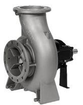

Brown Brothers Engineers have innovative solutions whatever your application. Contact us today about your requirements.
Ph: 1300 4 BBENG www.brownbros.com.au
Western Areas announced that its Odysseus Project in Western Australia is progressing as planned and to budget, with several key recent milestones achieved including the installation of a Schlumberger submersible pump to accelerate dewatering.
Installation of the Schlumberger submersible pump will add an additional 100 L/s pumping capacity from a depth of 500m below surface. It was installed in one of the existing rising main infrastructure holes. A step change in dewatering will be achieved via the introduction of this pump, water management ponds and high voltage reticulation.
The first phase of the early works schedule was the rehabilitation of the existing water management ponds (WMP 1-5) and the construction of two new evaporation ponds (WMP 8 and 9). These are now complete and being fully utilised. All the power requirements to run the surface

infrastructure, dewatering pumps and for commencement of the underground decline rehabilitation are in place utilising the existing power lines and hired gensets.
Since the start of the early works program, all dewatering activities have been from within the Cosmos open pit. To date over one million cubic metres of
water have been pumped into surface water management ponds, reducing the water level by 37m.
Western Areas Managing Director, Dan Lougher, said that the Company is pleased to be on track and on budget with the early capital works construction.
Every pump application is unique. That’s why Vogelsang offers a wide range of well-engineered, sturdy and powerful pump technology. Combined with our comprehensive series of features, options and continuous technical developments, we can provide the right rotary lobe pump for almost any application.
The most important characteristics of Vogelsang rotary lobe pumps are that they are self-priming even from a depth as much as 9 metres, they are resistant to dry running, and they also retain their high degree of efficiency if the medium being pumped contains foreign matter. Our customers in all industries have come to rely on our pumps, with their capacities of up to 1,400 m3/h and pressure of up to 16 bar, they can reliably convey low-viscosity to highly viscous media, either pure or with a high solid matter content.
This is a decisive advantage when economical solutions are required.
For more information
Vogelsang Pty Ltd
info@vogelsang.com.au
Tel: +61 2 46 47 8511
www.vogelsang.info

The Australian Renewable Energy Agency (ARENA) will provide $6 million in funding to repurpose South Australia’s Angas Zinc Mine in Strathalbyn — 60km southeast of Adelaide — into Australia’s first energy storage project using compressed air.
Hydrostor Australia will construct the 5MW/10MWh fuel-free Advanced Compressed Air Energy Storage (A-CAES) facility.
The $30 million commercial demonstration project will use the existing mine to develop a belowground air storage cavern that uses an innovative design to achieve emissions free energy storage. The facility will provide synchronous inertia, load shifting, frequency regulation and support for grid security and reliability.
Hydrostor’s project also received $3 million in funding from the South Australian Government through its Renewable Technology Fund.
Utilising the existing mine will help to increase renewable energy supply to the South Australian and national energy grid while also converting a brownfield site into a clean energy hub.
The technology works by using electricity from the grid to produce compressed air, which is stored in a purposebuilt underground cavern kept at constant pressure using hydrostatic head from a water column.
During charging, heat from the compressed air is collected and stored before the cooled air displaces water out of the cavern up to a water reservoir on the surface. To discharge, water flows back into the cavern forcing air to the surface under pressure where it is heated with the stored thermal energy and drives a turbine to generate electricity.
As a fuel-free storage technology, A-CAES has similar applications to pumped hydro. Most notably, it can provide the dispatchability required to ensure reliability of the power system

as more solar and wind power is installed.
ARENA CEO, Darren Miller, said the pilot project could open up a new form of renewable energy storage in Australia, which helps to support ARENA’s investment in delivering security and reliable electricity.
“While being a commercial demonstration at this stage, Hydrostor’s innovative way to store energy with air could add to Australia’s grid-scale storage capability, complementing pumped hydro and batteries.
“Compressed air storage has the potential to provide similar benefits to pumped hydro energy storage, however it has the added benefits of being flexible with location and topography, such as utilising a cavern already created at a disused mine site.
“It’s always exciting to see old brownfield sites given a new life and utilised for our transition to a cleaner and renewable future,” Mr Miller said.
Hydrostor CEO, Curtis VanWalleghem, said, “Hydrostor is very appreciative of the contributions from ARENA and the Government of South Australia for its first Australian A-CAES project.
“We’re excited to have the opportunity to demonstrate the significant benefits of adding our flexibly-sited, low-cost, bulk energy storage to the diverse range of technology helping Australia transition to a lower-cost, high system strength, cleaner electricity grid.”

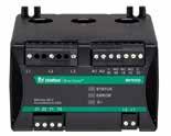
MP8000 SERIES
Bluetooth® Overload Relay
• Bluetooth® interface to allow programming by phone or tablet
• Programmable voltage and current settings
• 3 selectable restart options
• 4 programmable delay timers
• Flexible reset, through pushbutton on panel, remotely via the network
• Network communications capability
MPU-32
Motor Protection Unit
• Extends motor life with dynamic thermal modelling
• Provides protection through starting, running, & cooling cycles
• Prevents catastrophic failures and fires
• RTD temperature protection (MPS-RTD module) for high ambient or loss-of-ventilation protection
• Detects unhealthy supply conditions on 50Hz and variable frequency systems

6/8 Selkirk Drive, Noosaville, QLD 4566 P.O. Box 1965, Noosaville, QLD 4566 T 07 5455 5060 | F 07 5455 5062 E sales@startco.com.au www.startco.com.au


ewmont Mining’s Tanami Power Project has been completed safely and on schedule, including the installation of two power stations, a 66kV interconnected power line, and a 450km natural gas pipeline.
The pipeline was built and will be maintained by Australian Gas Infrastructure Group, and the power stations were constructed and will be operated by Zenith Energy. Capital costs are estimated at approximately $245 million with annual cash lease payments over a ten-year term beginning in 2019.
The project is expected to generate net cash savings of $34 per ounce from 2019 to 2023, delivering an Internal Rate of Return of greater than 50 per cent.
“In addition to lowering costs and carbon emissions, the completed Tanami Power Project will pave the way to further extend the life of the operation,” said Gary Goldberg, Chief Executive Officer at Newmont Mining.
“Consistent execution and delivery remain the hallmark of our ability to generate free cash flow and create long-term value for our shareholders and other stakeholders.
“Completion of the project coincides with Tanami pouring its ten millionth ounce of gold on the back of record production of 500,000 ounces last year.
“This achievement is a testament to the skill of our team as well as our valued partnership with the Warlpiri people, the Traditional Owners of the land.”

In March, Pump Industry Australia (PIA) held a technical meeting at Davey Water Products in Melbourne, with attendees hearing about future trends for pump resellers, including the new E3 energy rating legislation affecting the supply and sale of swimming pool pumps.
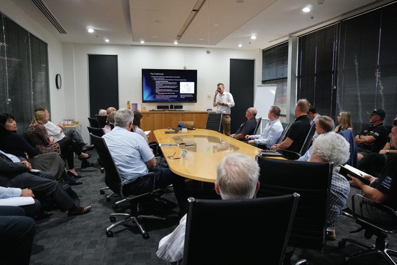
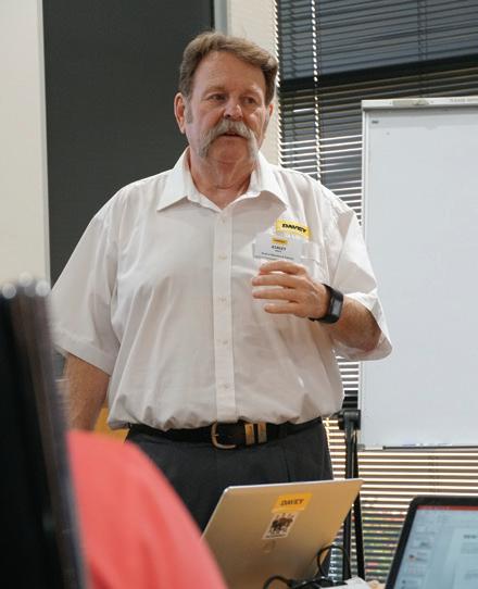
Attendees heard from Ashley White of Davey Water Products and Jamie Dixon, Global Technical Services Manager for White International, about trends that are affecting the industry now and in the future.
Ashley White spoke about technical and legislative changes in the industry for domestic resellers.
He spoke about what is driving these changes, citing consumer expectations, climate change, globalisation, the digital world and training as some of the major factors.
He also spoke about how businesses can meet these challenges, what they need to look out for and how they can set themselves apart in an ever increasing competitive market.
Jamie Dixon was the second speaker for the session and talked about the domestic and shallow well pumping for resellers.
He highlighted the potential of this sector as a driver for innovation, as well as its replacement market potential as water pumps are essential for domestic rural areas.
Following these presentations, attendees heard about the new Equipment Energy Efficiency (E3) Program affecting the supply and sale of swimming pool pumps.
New regulations are expected to be introduced in 2020, following the Council of Australian Governments (COAG) Energy Ministers’ agreement to the Decision Regulation Impact Statement in December 2018. These regulations aim to address barriers and behaviours preventing the pool pump
market from moving naturally to more efficient technologies, and will contribute to lowering unnecessarily high externality costs from swimming pool pumps, such as greenhouse gas emissions, peak loads on electricity distribution networks and residential noise pollution.
The E3 program will develop a Determination under the GEMS Act, ahead of introducing minimum energy performance standards (MEPS) levels and labelling. E3 is also working with Standards Australia to revise AS 5102.1‑2009, Performance of household electrical appliances – Swimming pool pump units, Part 1: Energy consumption and performance.
The following recommendations were accepted by the COAG Energy Ministers:
• Apply MEPS and mandatory labelling to pool pumps that fall within the specified ranges
• Update the Australian standard that measures the energy efficiency of swimming pool pumps
• Introduce a curved line star rating with higher requirements for smaller pumps and lower requirements for larger pumps to ensure that pool pumps are rated fairly
• Update the pool pump energy rating label and require the labels to be displayed either on the product, if displayed in store, or on the packaging
The PIA hosts a number of technical meetings and training sessions throughout the year for members and nonmembers. For more information or to become a member, visit the website at pumps.asn.au
Ebara has rethought the hydraulic design used in multistage pumps. Utilising the latest in computational fluid dynamics and design, followed by rigorous testing, Ebara has developed a unique impeller design that offers solutions and value to the customer — the Shurricane.
The imbalance of forces acting on the front and rear shrouds of a conventional impeller results in axial thrust. This thrust load is compounding in multistage pumps, and has to be allowed for in the pump design.
For pumps with conventional impellers, the existing solutions include having a thrust bearing built in the pump, or to use a special motor fitted with a larger thrust bearing. Both are costly and can be complicated. Another solution has been to simply have a smaller diameter back shroud to reduce the thrust.
Ebara has rethought the hydraulic design used in multistage pumps. Utilising the latest in computational fluid dynamics and design, followed by rigorous testing, Ebara has developed a unique impeller design that offers solutions and value to the customer.
The optimised shape of the Shurricane maintains high efficiencies and very significantly reduces the axial thrust — meaning that any standard IEC motor can be used and bearing life is improved.
Built like a Katana
A Katana is a traditional Japanese product manufactured with care and precision. Only years of experience can give the necessary capacity to build a masterpiece.
This is what Ebara does with its pumps. The result of over 100 years of Japanese experience in pump design and manufacturing, their pumps offer high-quality performance, reliability, and cutting-edge technology.
Ebara’s vertical multistage pumps are manufactured in Italy to the highest standards of quality, and achieve reliable operating performance by means of
strict technical evaluation criteria and control programs that involve the whole manufacturing process.
The range of Ebara vertical multistage pumps are suitable for a wide range of applications, in the industrial, commercial and agricultural fields. They can be used at water treatment plants (for reverse osmosis and filtration), for the pumping of hot or cold water for HVAC systems, for the pumping or boosting of water in general, and in boiler feed, irrigation and fire fighting systems.
The pumps can be coupled with any motor, anywhere. Optional materials are part of the unique hydraulic design, and there are optional connections for customers to consider.
Innovative hydraulic solutions
• Commercial motors can be fitted to all of the pump models without any modifications thanks to low pump axial thrust load
• Long life of the motor bearing
• Patent Application
Energy saving
• High pump efficiency with MEI (minimum efficiency index) > 0.7
• Fitted with high efficiency motors
• Suitable for use with Variable Frequency Drives for further energy savings
Piping connection options
• Various types of connections are available to best suit different installation requirements
• The external dimensions are to the industry standard, and are interchangeable with most other brands.
• The cartridge type shaft seal is able to be replaced without disassembling the motor bracket

• The spacer coupling allows easy maintenance without having to remove heavy motors 5.5 kW & above.
Smart plug solutions
• Air ventilation plug
• Water filling and sensor plug
• Commercial sensor fitting
• Tappings for suction and discharge pressure, and/or drain
The optimised shape of the new Shurricane impeller maintains high efficiencies and very significantly reduces the axial thrust – meaning that any standard IEC motor can be used, and bearing life is improved.


The new E10PX series from Caprari is the pinnacle of innovation and performance in pump technology.
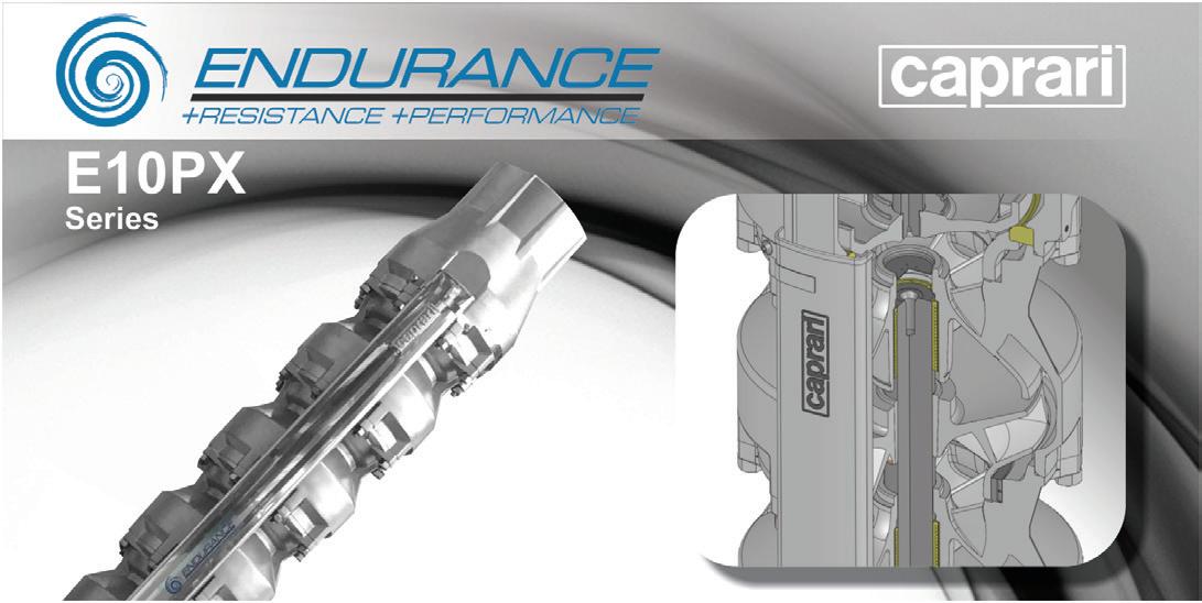
An extension of Caprari’s reputable Endurance range of borehole pumps, the E10PX Endurance series is the culmination of decades of international installation experience and is unparalleled in terms of hydraulic performance.
The sizing of components and selection of high-quality materials make the E10PX Endurance pumps unique in terms of their durability, efficiency and flexibility of application, with the precisioncast stainless steel design able to withstand harsh environmental conditions — including aggressive waters.
The shaft and coupling of the E10PX are made from Duplex for maximum reliability, and the pump-motor coupling area is fitted with DEFENDER® to provide additional protection against abrasion. From the beginning of installation, DEFENDER® protects the entire pumpset from electrochemical corrosion and galvanic currents by passivating the external stainless steel components.
The E10PX Endurance electric pumps have an innovative hydraulic design that allows them to operate at high flow rates with a smaller external diameter. They have an operating range covering duties normally met by 12” (or larger) pumps and deliver a high head per stage, making it a more compact pump for comparable hydraulic needs.
The pump design also means there is no need for special tools, making maintenance and servicing quick and easy.
The E10PX Endurance 10” borehole range can be used in a wide variety of applications, including captation from deep wells, RO, artificial snow making and other civil and industrial uses.
The Caprari E10PX Endurance — offering peace of mind, durability, efficiency and value.


Kelair Pumps Australia is strengthening its service offering with the acquisition of GT Water Technologies (GT Water), a family-owned company specialised in services around fire water tanks to the building and fire safety markets in the Melbourne area.
Established in 2012 and now with 11 employees, GT Water is a young, fastgrowing company based in Melbourne.
GT Water is particularly strong in pump systems and assemblies, with the main products being storage tanks and systems for fire suppression, hydraulic systems for stormwater, sewage and domestic hot water, as well as pump service and installation for industry.
“This is in line with AxFlow’s strategy of adding value through product selection, system design and construction, as well as local service.”

“Although a young company, GT Water has quickly established its service business, demonstrated strong, profitable growth and has a proven record of taking market share,” said Ole Weiner, CEO, AxFlow Holding (a Swedish-based fluids handling business, who owns the Brown Brothers Engineers Group, who in turn owns Kelair Pumps).
John Inkster, Managing Director of Kelair Pumps, also sees considerable potential in the acquisition.
“This is an opportunity for Kelair to expand its footprint in the building and fire markets,” Mr Inkster said.
“It also presents an opportunity for Kelair to bring fire water storage tanks into other regions.”
Aaron Monks, GT Water major shareholder, said, “I am really pleased to hand over the ownership to Kelair Pumps, and ultimately AxFlow. I was attracted to their long-term ownership view and strong values.
“With this sale, our company will have greater opportunities, and we can provide our employees, customers and suppliers a reliable partnership for many years to come.”


Kelair stock a wide range of high quality pump brands. Find the Brand you’re looking for.

From mining to pharmaceutical, Kelair has an extensive range for applications across all industries.

Whether you need Positive Displacement Pumps or Centrifugal Pumps, we’ve got one that will hit the target.

All our pumps are supported by our highly skilled service division for all your service needs.
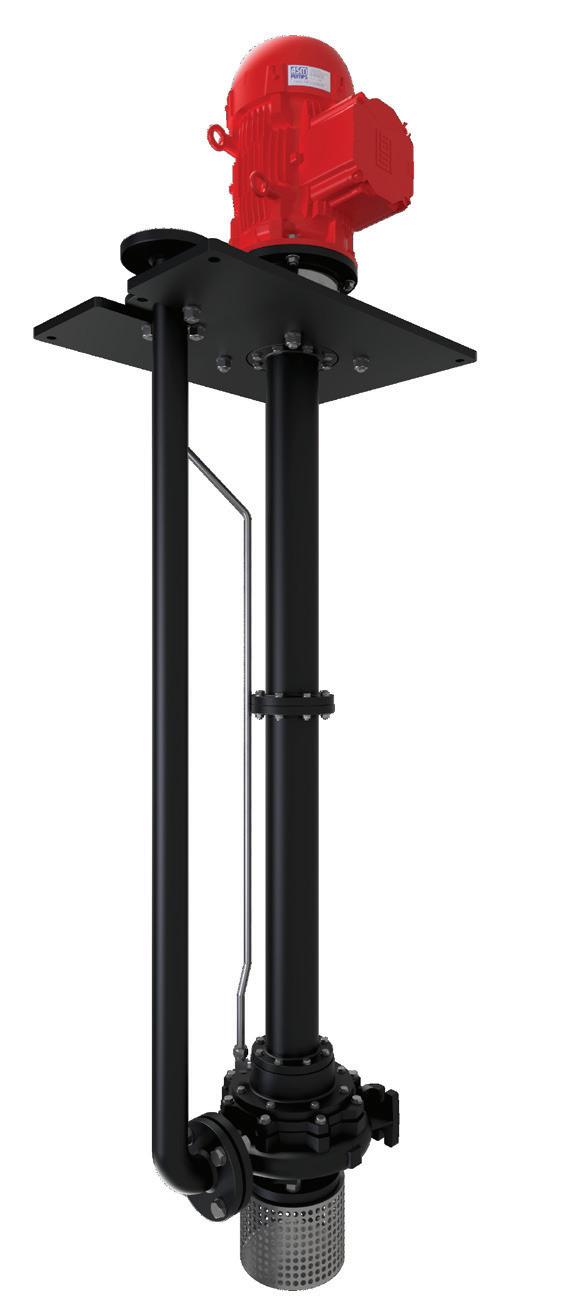
The key to successful, hassle free sump pumping is to eliminate priming issues.
Which is exactly how our ‘V’ Series Vertical shaft column pump works. Unlike a surface mounted unit, the ‘V’ Series is always primed as it’s submerged in the liquid, avoiding the need and expense of a suction line or foot valve and the NPSH restrictions associated with surface mounted pumps.
Its space saving design minimizes or eliminates floor space required for installation with the motor out of the liquid for easy maintenance and monitoring.
With the ability to pump water, suspended solids or semi viscous products and be used in high temperature applications and explosive atmospheres, the ‘V’ Series is also very versatile.
Save time, money and space up top, with an ASM ‘V’ Series pump down below. For more information contact ASM Pumps on (03) 9793 7577 or visit asmpumps.com.au
In 1919 things were a little different. The First World War had just ended and an unassuming businessman called Milton P. Levy from Dallas, Texas, started the National Disinfectant Company, offering only a handful of products. It didn’t seem like much at the time.
The work wasn’t glamorous. People didn’t think too hard about the soap their doctors used or how their water was treated, but it soon became clear that Milton was a pioneer in this new industry.
It turned out that Milton’s dedication to providing both quality products and service to his customers paid off. The company invested in research and development, and before long it produced almost all its own products.
When Milton died in 1946, his three sons took over the business, and they had a vision — to become a leader in the specialty maintenance market. That might not sound too exciting to most, but to the Levy brothers it was. “We love it,” they said, and so, it seems, did plenty of others.
Across the US, customers began regarding the NCH sales reps as maintenance experts, relaying their knowledge and expertise.
By the 50s and 60s offices started opening across the US, and then around the world. Now the company wasn’t just selling disinfectant, it was cleaning and conserving water, conserving energy, increasing safety, and decreasing waste. It was starting to change the world.
Today, NCH distributes to more than 50 countries, with over 8500 employees across six continents, and an extensive and varied product line. We’ve cleaned millions of gallons of water, saved gigawatts of power and kept thousands of kilos of toxic chemicals out of the environment.
Yet to this day, millions of people that benefit from the work we do have never even heard of NCH.
That’s ok with us, we’re not in it for the glory. Just like Milton P Levy when he founded the company 100 years ago, we want to make the world a better place.

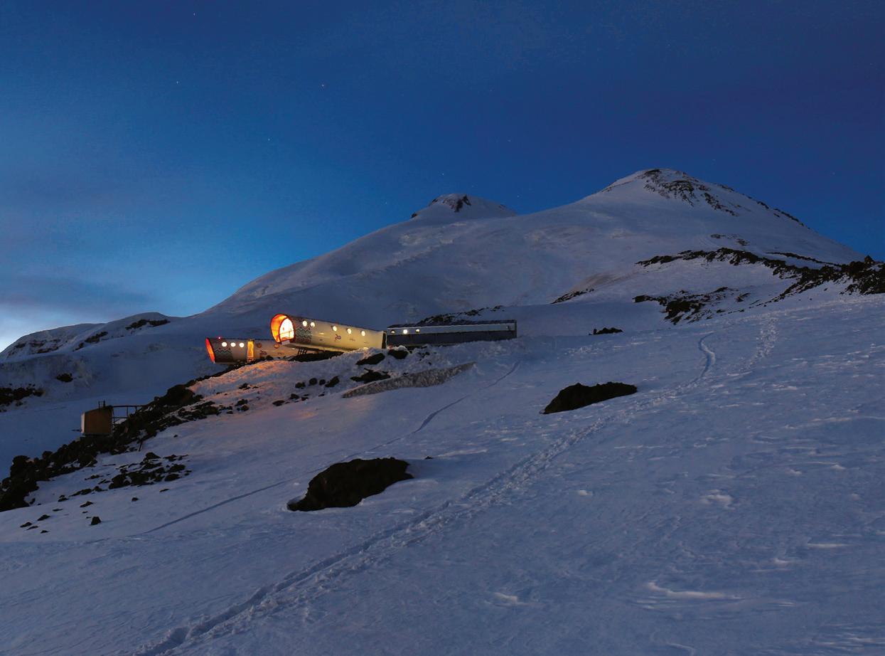
Whether you are operating in the alps or in a remote rural location, you can depend on FPT Industrial to provide reliable power. From the mountains to the sea, through fields and roads, FPT Industrial is the beating heart, powering any kind of mission.
FPT Industrial is even capable of taking power up to Mount Elbrus in the Caucasus, which peaks at a height of 5642m (18,510 feet).
The LEAPrus 3912 refuge was constructed at this altitude. However, calling it a “refuge” is misleading, as it is actually a very modern alpine station where design and comfort are the focus.
Thanks to one of the FPT Industrial power generators — the 3.2 litre F32 SM1A — this structure operates in even in the coldest temperatures (it can work in temperatures lower than -20°C). The generated energy is used to produce heat, melt the snow into hot and cold water, turn on the lights and run the wastewater drainage system.
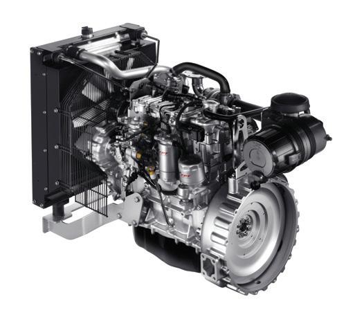
In the end, if life is possible at LEAPrus 3912, it’s because there is an FPT Industrial engine at its very heart!
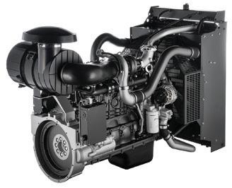
Proud of its 150 years of experience and know-how, FPT Industrial is strengthening its position as a worldwide provider of advanced powertrain solutions, which are focused on power generation — both for unregulated and regulated markets — with an extended portfolio covering from 30 to 600 kVA.
This year, FTP Industrial continues to leverage its technological excellence and product innovation, presenting engines that comply with emission legislations worldwide and always ensuring advantages on performance and efficiency.

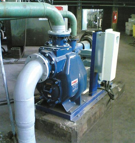
A NSW fruit juice manufacturer has recently selected Gorman-Rupp self-priming pumps for its wastewater service. The manufacturer selected Gorman-Rupp pumps because they were the safest option for operators and were considered the most economical solution, according to Gorman-Rupp distributors, Hydro Innovations.
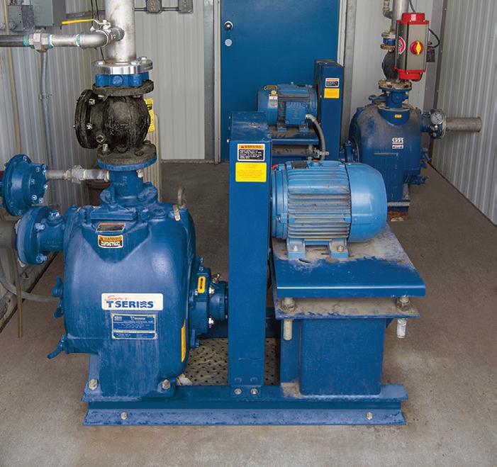
Gorman-Rupp pumps are installed at ground level — above the waste pit (up to 7.6m above water level) — so they can be monitored, inspected and repaired easily and safely. Other technologies are not so easy to monitor and often require the use of cranes and the opening of wet well covers, which expose operators to working over water and working at heights. GormanRupp pumps can be serviced safely by one person, with no confined space entry to worry about.
For this project, requiring a flow of 28 litres per second (L/s) at a total head of 12m, a Gorman-Rupp V3B60-B was selected. This pump is one of Gorman-Rupp’s “Ultra V Series” of pumps and is the most advanced self-priming wastewater pump on the market today. The pumps have additional safety features to protect both operators and equipment, and have the most advanced maintenance features available.
Some applications can be abrasive or corrosive (or both), so Gorman-Rupp Ultra V Series pumps have a range of materials to best cope with the application, including hardened iron for abrasive service, 316 grade stainless steel for corrosive applications, and CD4MCu (a hard duplex stainless steel) for abrasive and corrosive applications.
Wastewater pumps from Gorman-Rupp are available with flows from as little at 4 L/s through to 250 L/s.

For more information on Gorman-Rupp pumps, email Hydro Innovations at info@hydroinnovations.com.au.
• Eliminate confined spaces
• Eliminate the need for cranes
• Reduce blockages
• Reduce down time
• Increase efficiency




Let’s talk. Do you want to increase the productivity of your existing plant? Are you interested in knowing the heartbeat of your machinery so you can make better and more informed decisions?

Initiatives that improve plant and machinery efficiency are a topic of great relevance and importance to all stakeholders, including business owners, plant managers, maintenance managers and shareholders.
Achieving higher efficiencies and productivity effectively ensures that your machinery and processes are running at their most optimum level, which can help avoid nasty surprises.
But how to start a focused initiative can present a difficult decision.
Do you buy new machinery or improve the condition and output of your existing machinery?
How to evaluate the health of machinery easily and efficiently, so that you can visualise and then analyse the information, presents even more questions . These questions are extremely important in understanding the practical implementation of a possible solution before you commit to any particular technology.
In order to answer these questions, we first need to evaluate and understand the criticality of machines, such as downtime repercussions and possible failures associated with that piece of machinery.
Once these two underlying points have been identified, a range of sensors can be installed to help monitor — and potentially predict — the failure before it occurs. The use of sensors and associated technologies can warn organisations of impending machine failures and unplanned downtime.
An organisation can then allow for planned downtime and is appropriately equipped to manage the asset, precisely solving the problem reported. This leads to a reduction in costs, which will in turn increase machine uptime and availability.

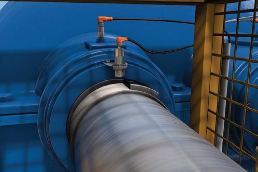
ifm has a range of sensors and analytic systems that can be easily installed and commissioned on rotating or non-rotating machinery. The sensors can be connected to intelligent gateways using IO-Link technology — so the data generated can be sent to a server and IT platforms — which is the basis for Industry 4.0.
Furthermore, ifm also has a range of options for monitoring the vibrations of machinery, with sensors that can help assist maintenance staff in monitoring unbalance, looseness, bearing damage, misalignment and cavitation etc.
All the information on the server can be visualised on ifm’s SmartObserver software — which makes the system plug and play — a solution that is both low cost and highly scalable to suit the individual machine or process.
Talk with us today to discuss your ideal solution.






Flowrox, formerly known as Larox Flowsys, has more than 40 years of experience in solidliquid separation, flow control, elastomer technology and technical textiles. Amongst others, Flowrox manufactures aggressive, abrasive and corrosive resistant pumps that can withstand the harshest conditions. In this case, Flowrox has provided low total cost of ownership solution for LKAB from Sweden, where rock solid content is extremely high.
For the new plant, LKAB chose LPP-T100 transfer pumps, which can pump up to 76 per cent solids.
“The fact that the hose pumps are suitable for paste and high-density slurries is important to us. The capability of the pumps to effectively pump solids is very crucial for us in the water treatment facilities. The slurry is dense enough to enable us to save water and maintain the flow,” states Åsa Partapuoli, Senior Process Engineer, LKAB.
Reliability is what LKAB is looking for in a pump
“We have been working with three pumps in the thickener plant for one year and they have been operating well. In terms of pump performance, the most important for us is that they function reliably. All other benefits come later. If a pump is not reliable, there is nothing else to benefit from,” states Ronny Martinson, Maintenance and Operation, LKAB.
The Flowrox hose pumps incorporate an advanced rolling design where larger particles can be handled in high pressure with minimal wear.
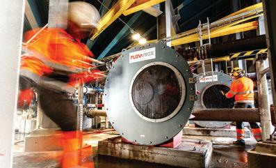
“The pumps can run dry and be operated 24/7. The pumps’ rolling design eliminates friction, maximises hose life and lowers energy consumption. Flowrox pumps are able to handle up to 76 per cent solids,” reveals Björn Gardelin, Minrox, the Flowrox representative in Sweden.
Flowrox is a family-owned global company headquartered in Finland, with products and services enhanced with IIoT solutions and intelligent systems. Flowrox serves a number of process industry applications, especially in mining, mineral, chemical, energy and environmental industries. Flowrox has subsidiaries in Australia, Chile, China, Republic of South Africa, Russia, Sweden and the US, as well as more than 230 sales representatives in 80 countries.
For more information, visit www.flowrox.com




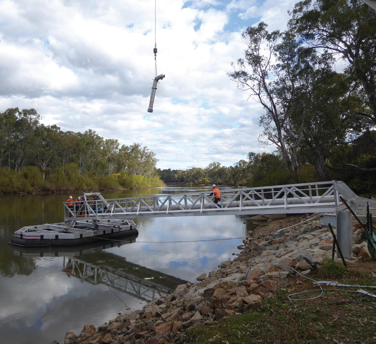
Faced with the challenge of low water levels, a shared recreational area and the need for easy maintenance, Federation Council in New South Wales had its work cut out for it to come up with a solution to replace the old, unserviceable Victoria St raw water pumping station in Corowa. With traditional pump station designs unable to provide a solution, the Council came up with the unique design of a floating pump station, sitting on the Murray River.
The town of Corowa is situated on the Murray River around 50km west of Albury, and its 6000 residents make up half the population of Federation Council. It has two raw water pumping stations delivering water to a distant water treatment plant which supplies water to the town.
Since it was built in 1967, the Victoria St raw water pumping station had been a liability, with consistent maintenance and operating issues leading to high capital expenditure and unreliable water supply. Identifying that the pump station would pose great costs and risk in the future, the Council undertook a six year campaign of study and reports to determine the best replacement option that met all of the design criteria and needs. The resulting solution was to replace it with a floating pump station.
The design dilemma
When the old Victoria St Pump Station was built to replace an older pump station as a compromise to building a water treatment plant, it was intended to provide good quality water to the town by pumping through a natural two-metre deep gravel filter bed in the river.
However, the pump station struggled with high suction head problems when the river was low, which led to the
pumps suffering cavitation damage and requiring frequent replacement. Furthermore, when the river was in flood, the pump station could only be accessed by boat.
Maintenance of the pump station posed additional problems, as the gravel filter bed could not be satisfactorily cleaned with the backwash system in place and was getting worse every year. This caused a ripple effect, as maintaining the three bore pumps was difficult because suction head losses were high, and they could not perform to their design duty, especially when the river was low.
The pump station was in desperate need of replacement. Yet significant research would need to be undertaken in order to design a pump station that was able to deliver the required flows; that was easily operated and maintained; that could be built with minimal construction risk so far as it affected cost and the environment; and didn’t impact recreational water skiing activities on the river.
Federation Council’s Special Projects Officer, Geoff Lewis, spoke of the design dilemma, “To reach deep water for the pump suction intakes meant extending the pipework well out into the river, but this would conflict with navigation on the river and interfere with speedboating.


“Traditional pump station designs were not going to overcome this problem and therefore Council staff had to come up with a concept that had to be easy to operate and maintain, be cost effective to build, and not adversely impact on the environment.”
Thinking outside the box
Of all the options considered by Federation Council, Mr Lewis said the floating pump station was the only one where all of the infrastructure was above water, providing the best maintenance and construction scenario, and offering a unique solution to the long-standing problems of the old pump station.
“The design allowed all of the fabrication work to be done off-site, in controlled conditions, with installation taking place quickly, with least risk.
“The only site work comprised of demolition of the old pump station, placing rock for erosion protection of the river bank, and constructing the concrete anchorage,” Mr Lewis said.
The contract was a design and construct contract, which was inclusive of all structure, pumps, pipework and electrics. This type of contract was necessary because of the interdependence of the structural design, and pump and pipework design.

Total Eden from Shepparton was awarded the contract, with Newcastle company Hunter H2O providing engineering support throughout the tender, design evaluation and construction supervision phases of the project.
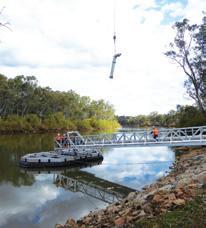
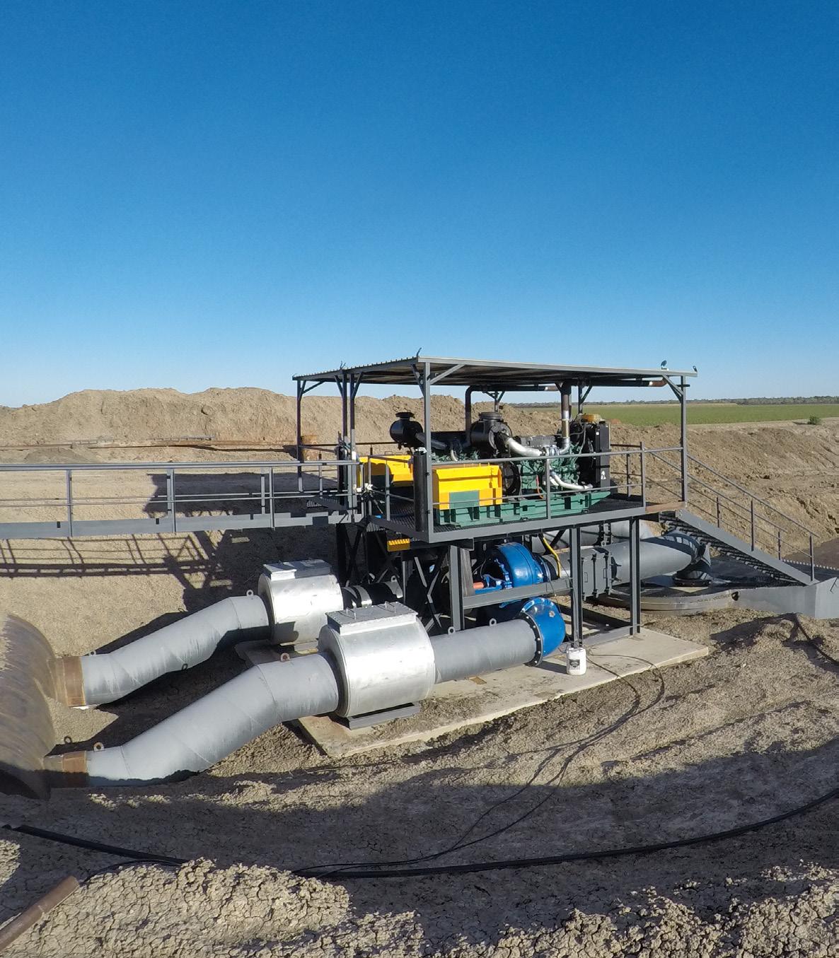
The floating pump station has gantry mounted horizontal centrifugal pumps located over a pontoon, and it is connected to the riverbank with a long walkway that supports the pipework and power cables, and anchors the pontoon to the riverbank.
The challenge for the new pump station will be to provide an installation that can pump water from a depth of less than 450mm.
“The main challenge was to have the pumps operating in sufficient water all year round especially in low river drought conditions,” Mr Lewis said.
“When selecting the pumps, the most important consideration was having sufficient immersion of the pump suctions in the water so that vortexing did not occur and therefore loss of flow. Equally the suctions had to be minimal depth so as not to strike the river bottom when the river is at its lowest level.
“Pump commissioning comprised operating at various flow and head duty points as the pumps have variable speed drives, and factory testing of motor performance was also undertaken. Site testing required operation at the required duty points for a minimum specified time period.
“Further testing remains to be done to determine if the correct length of suction pipes has been adopted for all conditions.”
As it is articulated, water can now be pumped at any river level, even in drought or flood conditions.
Maintenance and repair costs were also of significant importance, as they defined the nature of the equipment, and therefore the capital cost of the project. The persistent maintenance and operating issues of the previous pump station meant underground or underwater equipment was to be avoided, with ease of operation and maintenance the highest priority in Council’s final assessment of the proposal.
“The pump units can receive routine maintenance in situ, as they are open and easily accessible,” Mr Lewis said.
“A requirement of the contract was that if they had to be removed from site for maintenance, it would
need to be done without the need for a mobile crane.”
The gantry and pump bases are designed so that the pumps can be disconnected from the suction and delivery pipework and winched along skid rails up the gantry to the river bank. Once there, they can be picked up with a franna crane, or similar short reach truck mounted crane, for delivery to a workshop.
As the river is also a popular water skiing location, the design of the pontoon had to take this into consideration, and therefore had to be close enough to shore so as not to interfere with river navigation, but be far enough out to access deep water. This was achieved with a 22m long gantry which avoided any need for river bed excavation, but remained within the 25m navigation interference limit.
"Because the pump station is located above water, it had to be as maintenance-free as possible" Mr Lewis said.
“Material corrosion was the biggest risk, and consequently aluminium was selected for the structural elements, stainless steel for the piping and HDPE for the pontoon flotation due to the very high life expectancy of these materials.”
The pump station also needed to be able to resist flood debris loading and have secure flotation capacity. The foundation concrete block — which is on six metre deep piers that anchor the braced gantry — combined with twin stainless steel cables anchored to an upstream pier, provide security against flood loading. Flotation redundancy is achieved with capacity being double the load and accompanied by six separate flotation modules.
Project success
The $600,000 contract was completed in late 2018 and brought an end to the Council’s 50-year struggle to maintain a deteriorating pump station.
Federation Council General Manager, Adrian Butler, said, while the design of the pump station presented many challenges, the final result was a credit to all of the staff and contractors involved.

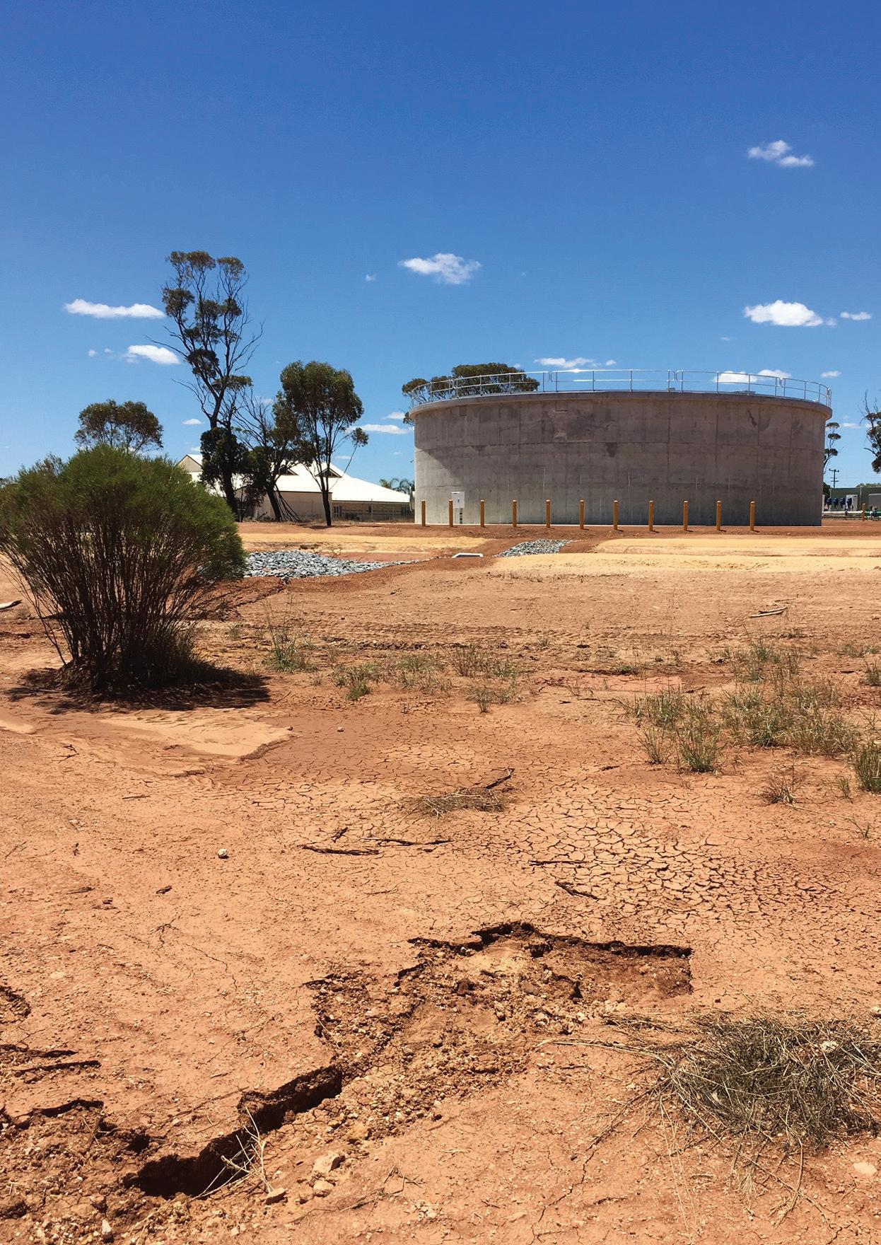

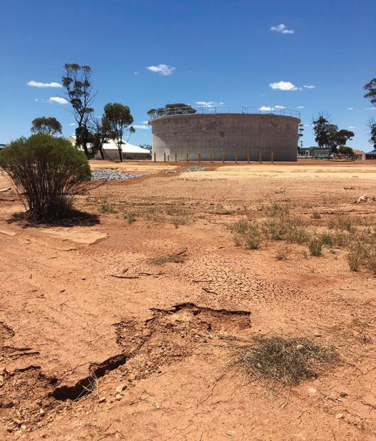
An $8.1 million project to upgrade the water infrastructure in Dalwallinu in Western Australia has been completed, providing security of supply and catering for future growth and development in the town, along with delivering a more consistent water pressure for the 350 residents and businesses.
Water Corporation undertook the works which included the construction of a new, larger capacity concrete water storage tank, two new booster pump stations and 2.2km of underground water main connecting the new tank to the existing scheme.
The new tank can hold up to two million litres of drinking water for the town and was constructed on Water Corporation land in Dalwallinu, opposite Strickland Drive.
The new underground pipeline was installed along Leahy Street, Strickland Drive, Great Northern Highway and Watheroo Road. The second booster pump station was built at the Water Corporation’s existing Pithara site, about 20km from Dalwallinu.
Western Australian Minister for Water, Dave Kelly, said, “The new water tank, two pump stations and pipeline will provide the Dalwallinu community with greater security of supply for generations to come.”
A spokesperson for Water Corporation said the pumps installed at the tank site were principal supplied and several factors were taken into consideration during the procurement process.
“The vendor provided the selected pumps on a metal skid in accordance with the design requirements. The pumps for the Pithara Pump Station were supplied and installed by the construction contractor DM Civil in accordance with the specification,” the spokesperson said.
“Several factors are important in pump selection. Most important is the hydraulic suitability as indicated by the pump performance curve and efficiency at the duty point/s. For this project there were several different duty points to consider, according to differing upstream and downstream conditions.
“Energy efficiency is an important aspect of pump selection. The whole-of-life cost is calculated taking into account pump efficiency at the planned duty point.
“Pump reliability, the reputation of the pump manufacturer and ongoing maintenance requirements are also considered.”
Water Corporation undertook testing on the pumps, including Factory Acceptance Tests and Site Acceptance Tests, as well as inspection at the point of delivery. In situ pump testing includes measuring the output of the pump against the actual energy consumption at the intended duty point/s.
The spokesperson said that maintenance and repair schedule and costs were an important consideration and formed part of the whole-of-life cost calculation.
“All of Water Corporation’s infrastructure projects have regular maintenance plans. Our operators carry out on-site servicing and routine maintenance of Water Corporation infrastructure.
“Maintenance includes a regular efficiency check and replacing pumps every three to six years depending on pump criticality and efficiency testing.”
Construction on the project started in February 2018 and was completed in January 2019.
About 25 Western Australian workers were involved in the project, with Water Corporation supporting local businesses and workers throughout the project, including locals employed by three Dalwallinu businesses that were awarded contracts.
“It was fantastic to support local businesses and WA workers through this project, with three Dalwallinu companies carrying out these infrastructure upgrades,” Mr Kelly said.

It can take weeks to reline and replace corroding underground water pipelines to renew and maintain them. At the same time, households do not want to have their water supply cut off during this maintenance period.
Faced with the challenge of refurbishing its water mains pipeline without impacting customer water supply, Yarra Valley Water approached Crusader Hose to find a solution.
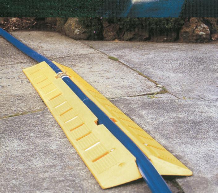
Yarra Valley Water in conjunction with Crusader Hose developed the Pureline system using the Aqualine, a potable water AS4020 approved layflat hose for temporary water bypass. This system incorporates a bypass hose which is unrolled and connected to each household along the street whilst the mains water supply is repaired. Drinking water can then be delivered to customers in an efficient and costeffective method without interruption while maintenance work is being carried without interruption out.
Aqualine is a high-pressure layflat hose constructed

with woven high-tenacity polyester yarn and covered with thermoplastic polyurethane to deliver high-working pressure and abrasion resistance during deployment and retrieval. The potable water approved hose is rolled out as a temporary water supply system while the utility carries out pipeline refurbishment works.
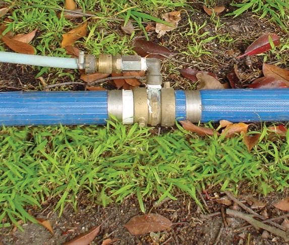
The hose can be cut to suit any length — in this case 9m lengths were required — and a T piece coupling is attached at each end. From these outlets, households are connected to the main line while pipe renewal or refurbishment takes place.
A major customer for this system has been Yarra Valley Water. The layflat hose has ensured that its clients are never disconnected from their water supply for longer than four hours, giving the utility plenty of time to carry out refurbishment works. The system can be in place for weeks and includes driveway plus road crossings.
When the pipeline renewal is completed, Aqualine can easily be rolled up and moved to the next location for deployment.
Today Aqualine is widely used and adopted by major utilities contractors to carry out their water mains renewal, ensuring uninterrupted water supply to households across Victoria and New South Wales.


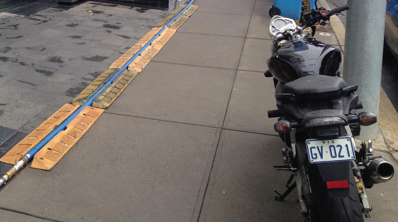


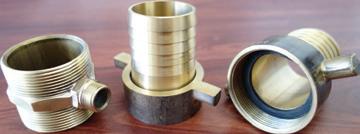


Aqualine is rolled out as a temporary water supply system while the Utility carries out pipeline refurbishment works. The hose is usually cut into 9m lengths and a T piece coupling is attached at each end. From these outlets, customers can be connected to the main line, while pipe renewal or refurbishment takes place. It is ideal for:
•Civil works
•Mining projects
•Potable bypass by utilities while refurbishing damaged water pipes
Main Features


Portable water approved to AS4020
500m can be easily rolled up onto a drum
Easy and compact for transport
Secure couplings stay on under high pressure
Can be made in any length
Large range of diameters available
Reeling system also available


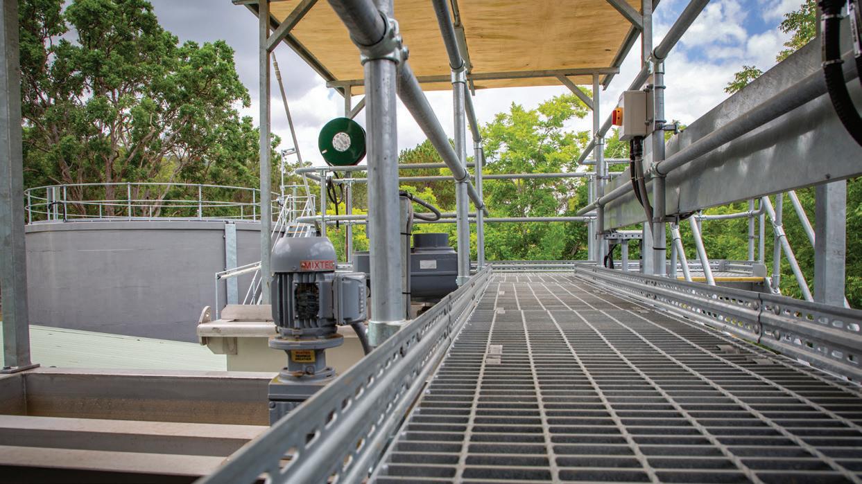
With a water source prone to highly variable raw water quality during weather events and a growing population, the Canungra Water Treatment Plant needed to be upgraded to improve water security for the region in the future. In 2016, Seqwater begun construction on the new $4 million plant, able to produce 1.5 million litres of treated drinking water each day.
Located in South East Queensland’s Scenic Rim Region, Canungra’s population is expected to triple over the next 20 years, and the standalone water supply system providing water to the township and residential surrounds was nearing the end of its service life.
Originally commissioned in 1975, the Canungra Water Treatment Plant hadn’t had any major upgrades or additional works carried out in over 35 years outside of the addition of a fluoride dosing system in 2009.
An upgrade was essential and was built in line with Seqwater’s Water Security Program, a 30-year plan to secure water across the region.
Increasing treatment capabilities
The original treatment plant was capable of treating 400,000 litres of water per day, which it drew from Canungra Creek. However, the creek has a high potential for increased turbidity in the raw water, with NTU levels peaking in excess of 100 (the maximum treatment capability of the original
plant) during rain events. In these cases, the plant would be forced to temporarily switch off until the creek settled.
This susceptibility to rapid changes in raw water quality meant it was necessary to upgrade the facility with membrane filtration technology, which is able to remove particles from water over a wider range of raw water turbidites. This allows the water treatment plant to continue to treat water during rainfall events.
The water is now screened and pumped at the raw water inlet structure, with two submersible pumps that are run in a duty/standby arrangement. The water is then dosed with aluminum chlorohydrate (ACH), which is a change from the type of coagulant used in the old plant.
“The use of ACH is recommended with the use of the membrane filtration, and provides other benefits such as giving us a broader dose range which is of a great benefit when treating ever changing creek water,” Seqwater Supply Operations Coordinator, Craig Bolin, said.
The dosed water is then pumped into the inlet structure and continues through the flocculation and clarification processes, where a large percentage of the solids, heavy metals and organics are removed prior to filtration — with the addition of pre-chlorination after clarification.
At this stage, the water is then filtered through the ultramembrane filtration process. There are two membrane filtration trains — again operated in a duty/standby arrangement — which filter the clarified water. Ancillary systems include backwashing, chemical cleaning and neutralisation, and membrane testing to verify the integrity of the membranes. After filtration, sodium hydroxide is dosed for pH adjustment, sodium hypochlorite for disinfection and sodium fluoride.
With the new plant now capable of treating nearly four times the amount of water as the original plant, and able to treat raw water with turbidity up to 1000NTU, water quality issues are a thing of the past.
Expanding storage capacity
With the treated water pumped from on-site storage to the Appel Street reservoir on a demand basis determined by the reservoir level, increasing the water storage was also a high priority. The limited storage capacity of the original plant — 40,000 litres — compounded the risk of water shortages for the community whenever the plant was closed for maintenance, or because of dirty water due to rain events.
The new plant has increased its site storage capacity to 310,000 litres. With more water able to be stored on site, it puts Seqwater in a better position to supplement the nearby reservoirs when required.
The new Canungra plant was developed as a brownfield project, built on the same site as the existing plant.
Mr Bolin said maintaining the water supply to the Canungra network during the upgrade was imperative, and proved to be a significant challenge as the original plant remained in operation while the new plant was being constructed around it. The construction involved progressively decommissioning and removing existing structural components of the old plant while also installing the new facility.
“As the facility was upgraded, new infrastructure had to be integrated into system, all while continuing to treat water and meet supply demands,” Mr Bolin said.
“It required Seqwater working together with contractor Monadelphous and retailer Queensland Urban Utilities to manage the various transitions from the old plant to the new.”
Pump procurement and selection
Mr Bolin said there were a number of factors that were considered when selecting the pumps.
“Matching the pump’s capability to deliver the right pressure and energy to suit the flow requirements for treatment is the most important factor when selecting a pump,” Mr Bolin said.
“The other major consideration is the actual fit — making sure the pump curve fits into the system curve properly. The pumps have to be matched to exact specifications otherwise they are at risk of becoming damaged, overheating or impacting the flow rate.”
Seqwater Senior Project Manager, Allan Cupitt, said finding pumps that met the specifications for the project proved to be a challenge.

“A challenge arose when we couldn’t locate the brand of pump that fit in with our systems, so we had to find a replacement with the right specifications that would allow the pump curve to properly intersect with the system curve.”
Once the pumps had been selected, installed and the required testing had taken place, including pressure testing for leaks, the pumps were operated through their required flow ranges. During this process, flow and pressure are monitored along with power factors such as temperature and vibration.
Mr Bolin said the treatment plant is maintained via scheduled tasks established by the manufacturer’s recommendation.
“The Seqwater maintenance section carries out this schedule, along with external providers for any specialised maintenance service,” Mr Bolin said.
“Seqwater also undertakes its own internal maintenance, which is over and above the manufacturer’s specifications.
"Water treatment plant operators continuously monitor instrumentation with inspections carried out on a daily basis. Inspections include sampling, instrument verification and calibration. Repairs or adjustments are then made if needed.”
Construction started in 2016 and is now complete, and the new water treatment plant is operational.
Queensland Minister, Mark Furner, was pleased with the results, explaining that the $4 million plant would be able to cater to the growing Canungra community and its increased water demand in the future.
“The new plant will be able to produce 1.5 million litres of treated drinking water each day...ensuring we can meet the community's future water needs,” Mr Furner said.
Scenic Rim Regional Council Mayor, Greg Christensen, said the new plant is important in supporting the community into the future.

“A secure and reliable water supply is critical to Canungra’s continued prosperity and the health of its residents and the environment,” Mr Christensen said.
“This project complements Seqwaters plans to connect Beaudesert and Wyaralong Dam to the SEQ Water Grid for the first time, to ensure the future water supply security for the Scenic Rim.”
The Canungra Water Treatment Plant is a





Much of the irrigation infrastructure in northern Victoria that has reached the end of its service life results in hundreds of gigalitres of water wasted each year due to leakage, seepage and evaporation. The Swan Hill Modernisation Project (SHMP) is one of the many projects being undertaken by the Connections Project to modernise irrigation infrastructure and secure the region’s farming future. The broad scope of project works includes upgrading existing and constructing new pump stations.

The SHMP is part of a $2 billion plan making it Australia’s largest program of irrigation modernisation works. Jointly funded by the Victorian and Australian Governments, the Connections Project is upgrading the Goulburn Murray Irrigation District’s water delivery network. Once complete, it is estimated average annual water savings of 429GL will be achieved and irrigation water use efficiency will be increased from around 70 per cent to at least 85 per cent.
To achieve these savings, many 100-year-old assets that have reached the end of their lifespan or were losing water to leakage, seepage and evaporation are being upgraded or replaced.
The SHMP was a staged project with works beginning in 2012 to upgrade Fish Point Weir, lower the Little Murray Weir, and install native fish passages at both these locations. Other works undertaken were converting the No. 9 Channel off-take from the Little Murray Weir to a pump station, upgrading the No. 10 pump station and constructing an interconnector between the No.9 and No. 10 Channels north of Swan Hill.
Frank Fisseler, Connections Project – Project Director, said a number of projects took place to allow for the decommissioning of the No. 9 Channel, including:
• Little Murray River
» New gates and vertical slot fishway were installed at Fish Point Weir
» Little Murray River (LMR) weir height reduced by 1.9m and construction of a vertical slot fishway
» Due to the lowering of LMR, a pump station was installed to lift irrigation water from LMR to the start of the No. 9 Channel (200ML/d pump station)
» A pipeline connection from the No. 9 Channel to the 1A/9 Channel was installed
» 22 irrigators of the LMR supply points were changed from a gravity to pumped supply
• No. 10 pump station
» The three 100ML/d pumps that lift irrigation water from the Murray River into the No. 10 Channel system were replaced. The electrical supply into the pump station was upgraded along with the control panel and control room
• 1/10 interconnector pipeline
» In order for the No. 9 Channel to be decommissioned through Swan Hill, a 120ML/d pump station and 3800m pipeline from the No.10 Channel were installed to ensure water deliveries north of Swan Hill township
In May 2018, the final stages of works for the SHMP began, including constructing a northern and southern pump station, and approximately 8km of HDPE pipeline was installed to supply customers around the Swan Hill township area.
Construction works were completed in late 2018, and the SHMP is now contributing about 15GL of water savings to the project’s overall target, and were prioritised due to the water savings and increased efficiencies that were identified for irrigators.
Designing the new pump stations
Mr Fisseler said extensive community consultation took place to plan this fit-for-purpose, complex program of upgrades to modernise the irrigation system incorporating two new pump stations.
Pump selection was based on performance, efficiency, pump sensors available to be connected into Goulburn-Murray Water’s SCADA network, and motors suited for VSDs.
“The southern pump station is of a wet well design using three Xylem submersible pumps, two of which are approximately 11ML/d flow rate each and a smaller pump of 1ML/d,” Mr Fisseler said.
“The northern pump station is of similar demand and designed as a booster pump station off an existing pressurised irrigation pipeline using two Lowara inline vertical pumps of 11ML/d each, and a smaller 1 ML/d pumps.
“Post construction commissioning and performance testing was carried out on both pump stations to ensure that they meet the design intent of the system.
“The pump stations feed irrigation water into pipelines under pressure to meet the demands of Goulburn-Murray Water customers. There was an extensive consultation period prior to preliminary design of the pipelines and further discussions with customers took place through a ‘pop up’ office.”
Mr Fisseler said the Connections Project successfully met the major challenge to ensure design could meet the need and demand of a diverse range of customers including:
• Irrigation supply for horticulture
• Stock and domestic supply
• Connection to gravity syndicates
• Connection to existing pumped pressurised syndicates
Maintaining the pump stations

Mr Fisseler said Goulburn-Murray Water carries out preventive maintenance programs on all of its pump stations, and this was taken into account during the project planning.
“Access to pump supplier technical staff and availability of spare parts were considered during the tender assessment for the pump supplier,” Mr Fisseler said.
“Goulburn-Murray Water pump stations are connected to their extensive SCADA network and are monitored 24/7 during the irrigation season. Goulburn-Murray Water’s preventive maintenance program continues to ensure pump stations are maintained to a high degree of certainty that they will meet the irrigation demand of their customers through regular visual inspections, twice yearly inspection, programmed maintenance during the irrigation ‘off’ season, and review of their operational performance.”
What’s next for the Connections Project?
The Connections Project is scheduled to be completed in 2020 and is on track to achieve all milestones including the 429GL of water savings.
“The $2 billion investment is revitalising the region, maintaining environmental values and helping to create an irrigation system that is second to none in the world with vastly improved water delivery efficiency from about 70 to 85 per cent,” Mr Fisseler said.

A comprehensive testing program of conventional large mixed flow pumps typically used on cotton irrigation farms has found that these pumps, if correctly tuned, can operate at high efficiency levels with reduced energy costs and lower carbon emissions.
The work was carried out by engineers from the University of Southern Queensland’s National Centre for Engineering in Agriculture (NCEA) in Toowoomba in a project funded by the Commonwealth Department of Industry and Science, and the Cotton Research and Development Corporation (CRDC).
NCEA water and irrigation specialist, Joseph Foley, said the aim was to test the large mixed flow pumps that dominated the irrigation industry to get a clear picture of how they were performing.
“Given our past work has shown that irrigation pumping is the largest energy consumption component on farm, we thought it wise to focus on the large 26 inch mixed flow pumps and to fathom how well this 50-year-old technology can operate,” he said.
“We initially thought they would not perform well below their curve, but our test results clearly indicate they can
perform quite well, similar to the large axial flow pumps but at a fraction of the capital cost.”
Dr Foley said that in most of the situations they looked at, while the pumps had the potential to perform well, they were typically being operated to the right of their curve at the low efficiency points in their range of capabilities.
He said significant savings were possible when the pumps were tested, their current performance analysed, and adjustments made to the pump speed, operating head and pump flow rate.
“In each of these cases we have been able to make recommendations that will drastically reduce the energy consumption for the volume pumped,” he said.
“In one instance, we have been able to knock the energy consumption down by 46 per cent.”
Dr Foley said one of the most critical components to analyse around any pumping station was the Total Dynamic
Head (TDH) at which the pump discharged its water flow rate.
“The Total Dynamic Head (TDH) is a measure of the energy per unit weight added by the pump to the water to overcome the static lift, the friction head loss and minor head losses,” he said.
“The larger the TDH becomes, the higher the pumping costs per ML will be in any pump station.
“The static lift component of the TDH can’t be reduced at any one point in time, but the friction and minor loss components can be significantly reduced if the flow rate can be reduced, or if larger valves and fittings can be installed at the pump station.

“The minor head loss component of the TDH is something that can be reduced through an engineering re-design of the pump station pipework, so that it is no longer a major proportion of the pump’s TDH.”
Diesel energy savings of over $1500 per season are expected with a new impeller in the pump, providing payback in three to four years, and reducing emissions by four tonnes of CO2e each season.
In one of the tests on an electric 26 inch mixed flow pump, Dr Foley said it was found that the four metres of head loss could be reduced substantially by replacing the existing angled cut suction pipe entry and grate with a smooth bell-mouthed entry.
“This would reduce the TDH from seven metres to 5.5 metres, reducing pumping costs by 21 per cent to $6.30 per ML, from the current $8.04/ML,” he said.
Another recommendation to reduce pumping costs at that site was to bring into service an adjacent, unused tractor-PTO-driven 26 inch mixed flow pump, allowing two pumps to operate and pump speeds to be reduced substantially but maintain the delivery rate of 150ML/day.
Dr Foley said by resetting each pump to deliver 80 ML/day, pump efficiency would improve from 75 per cent to 88 per cent, plus the slower water velocities would reduce head loss from four metres to 1.3m.
“The same total flow rate is provided, but at a drastically reduced pumping cost of $4.27/ML, down from $8.04/ML,” he said.
“This reduced the energy consumption from 29.5 kWh per ML to 15.6 kW.h per ML, saving over $11,000 in a ‘typical’ season of pumping, and reduced emissions from 76.2 tonnes

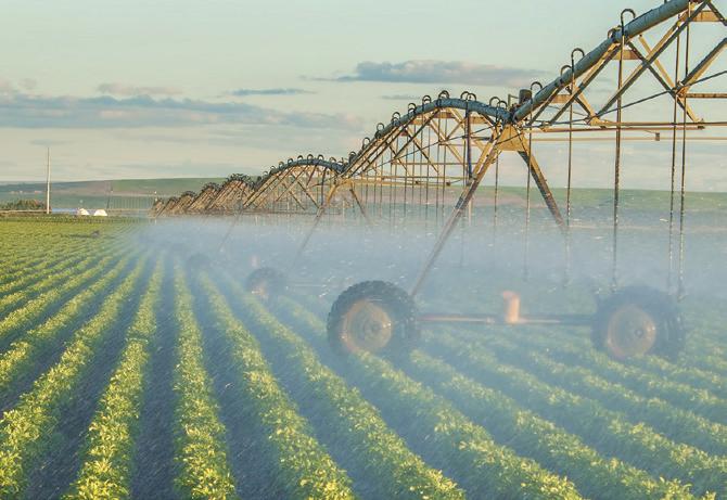


CO2-e (CO2 equivalent) to 40.3 tonnes CO2-e per season.”
In a separate test of a 20 inch diesel mixed flow pump, it was found the pump was operating more than 12 per cent below the manufacturer’s benchmark, and reducing the flow rate accordingly.
One of the key recommendations was to reconfigure the pump’s drive to lower the speed, resulting in a 30 per cent reduction in pumping costs.
This could reduce the costs from $8.40/ML to $5.00/ ML and about $10,000 in a typical season, but would mean reduction from 60ML per day down to 23ML per day.
With expected capital costs for a second pump installed being around $40,000, payback on pumping costs at the required flow rate are around four years, and would reduce emissions by nearly 27 tonnes of CO2e per year.
Funding from the Commonwealth Department of Industry and Science was made available under the Energy Efficiency Information Grants scheme to the Cotton Research and Development Corporation for engineers at the National Centre for Engineering in Agriculture to complete measurement and analysis on a number of large mixed pump stations on irrigated cotton farms.
This case study was originally published by the cotton industry’s extension program, CottonInfo.
To view more irrigation case studies, visit www.cottoninfo.com.au.

Irrigation equipment works hard, so it needs a hard-working engine. Meet Hatz Diesel’s compact and all new H-50 series.
• Up to 90 kg lighter than other engines in the power range
• Long engine life and premium components
• 500-hour maintenance interval
• 18.4 kW to 62 kW*
• Unsurpassed fuel efficiency
*(intermittent loading / ISO 3046-1)
Large areas of eastern Australia have been in drought for a long period of time, with some areas experiencing drought for up to seven years. This has resulted in dry conditions and surface water scarcity, and a higher dependence on groundwater resources. On top of this, increasing diesel and electricity prices have put pressure on irrigated agricultural production. This has led to irrigators seeking other cost-effective options for pumping water to help them get through the drought.
Solar PV has become a popular option in agricultural applications due to its scalability, and it is a proven and widely used technology in Australia and around the globe. This, coupled with government rebates, has seen irrigators increasingly move towards solar as a more costeffective alternative to traditional diesel and electric pumps.
According to Malcolm Eyre, Managing Director at Franklin Electric, solar pumps are becoming increasingly popular as they come in different types — including submersible which is ideal for drought affected areas where groundwater is relied upon — different integration configurations are possible, and they reduce power bills.
“While solar pumps have been expensive in the past, they have quickly become a viable option for most irrigators.
“Their key benefit is that solar pump systems can be sized to meet any scale of power demand, so the amount of water pumped is only limited to the number of solar PVs you have.
“They can also be integrated with mains electricity or diesel to create a hybrid solution to keep operations going even if there is limited sunlight, and they can be set up to only power part of an irrigation system if desired.”
Solar powered pumping
Malcolm said that solar pump technology has come a long way since it was first introduced, and it is on the cutting edge of design and innovation. This means these pumps are optimised to provide the most water for the least amount of energy possible, so irrigators can pump more water with the available sunlight, making them extremely energy efficient.
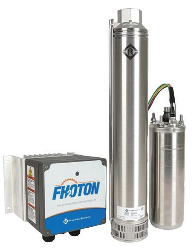
“By utilising quality components, innovative thinking based on global market inputs, and technical expertise in groundwater pumping, Franklin Electric has developed the Fhoton SolarPAK, SubDrive SolarPAK, and larger engineered systems.
“These submersible solar pump systems are rugged and have a high-output, which make them ideal for harsh and remote environments.
“Because these systems are submersible they can be used in drought affected areas where groundwater needs to be pumped, as well as for a range of other applications such as livestock watering, rural water supply, irrigation systems, vineyards etc.
“These systems come in a variety of sizes to suit a range of applications and can be used in a hybrid system, where electricity or diesel help power irrigation systems when there is not enough light.”
As well as helping irrigators save on electricity costs, the solar pump systems from Franklin Electric also come with builtin diagnostic and protection features.
“The Fhoton SolarPAK’s built-in diagnostic and protection features help prevent surge, underload/dry run, overvoltage, locked pump, open circuit, short circuit, overheated controller, reverse polarity and deadhead. It also has a soft start feature to prevent waterhammer and increase system life.
“These help prevent damage to the pump and motor, which in turn provides cost savings in the future as less maintenance will be required.”
For more information, visit www.franklinwater.com/au.


In this Queensland Farmers Federation case study, a vegetable farm in Stanthorpe installed variable speed controls and a solar photovoltaic system as part of an irrigation upgrade that saw an energy saving of 25-30 per cent.
The farm, near Amiens in Southern Queensland, produces vegetables for supply to supermarkets. The main crops are iceberg lettuce, wombok, celery, broccoli and silverbeet. The site includes a main packing shed that contains cold rooms, vacuum coolers and ice machines as well as the farm office. All crops grown are quite water-intensive. Pumping is required to supply the large sprinkler irrigation network for most of the growing season from August to May.
The site energy consumption consists of:
• Main packing shed that houses processing equipment
• Four vacuum coolers that bring the crops rapidly down to 2°C
• Six cold rooms with associated refrigeration equipment that stores crops awaiting transport
• 17 irrigation pumps
Action
An audit of site energy consumption evaluated:
• Variable speed control of pumps and compressors
• Pump refurbishment
• Refrigeration coil remediation
• Solar photovoltaic (PV) installation
• Temperature control system improvement
• Refrigeration compressor upgrade
Results
Of the energy saving opportunities evaluated, nine initiatives were identified with potential energy savings of 11 per cent of the site total and a combined payback period of approximately 1.4 years.
The audit report recommendations included initiatives to install variable speed drives on a 45kW and a 37kW irrigation pump to improve efficiency at lower flow rates, as well as refurbishment of the same pumps to resolve lower than expected efficiency.
Other recommendations included installation of a 5kW solar PV system on the main packing shed, remediation of refrigeration coils to address contaminants, implementation of variable speed drives on compressors and upgrade of cold room temperature control system. The energy audit also included a recommendation for an electricity tariff review to realise potential savings of $24,402 p.a.
Following the audit report recommendations, the customer proceeded with installation of variable speed drives on two 37kW pumps on the property that were not originally assessed as part of this energy audit but nonetheless provided opportunity for energy savings. Measurement and verification was completed on these pump systems following implementation and outcomes are shown with associated operating cost savings.
Actual
Variable speed control of irrigation pumps is now providing energy and cost savings for the customer.
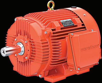
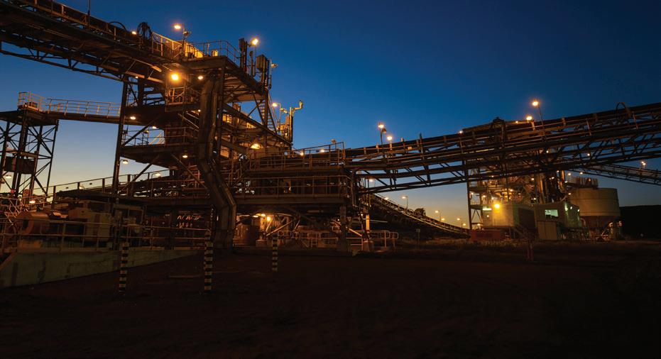
For more information please contact us on 1300 888 853 or email salesAUvic@regalbeloit.com www.RegalBeloit.com / www.regalaustralia.com Creating a better tomorrow™...
Suppliers today generally seem to be running wild with the desire to create more value for their clients, providing extra features or services “for free”. This in turn creates a false value perception with respect to what customers actually need and then expect.
With this ever-increasing demand and expectation for extra “stuff”, how do manufactures, suppliers, designers and specifiers ensure that what is offered or asked for is actually needed or useful? It’s worth remembering that these extras, while often given as a gratuity to entice purchase, do actually incur a cost that will manifest somewhere!
Care should be exercised to make sure that what is specified is actually needed and will provide a tangible, measurable benefit. For example, a high-efficiency motor running all day against a partially closed valve for flow control will not be providing an energy saving benefit when compared to other methods of flow control, such as the use of a variable speed drive matched with the pump to meet system demand, or sizing pumps more appropriately to duty point.
Equally, a high IP protection rating on a motor in a clean dry plant room won’t provide any additional protection against ingress of the (non-existent) water or dust. Does a motor that has been selected to operate in a system to a maximum of 80 per cent of its rated kW in a 40 degree ambient really need Class H insulation?
The answer to over specifying depends on various considerations. While it shouldn’t be argued that things like high efficiency, high IP ratings and high insulation class materials are not worthwhile, it should be considered that the use and assumed benefit — and the resulting cost — should be balanced.
Often when challenging a specification with a “why?”, the answer is regularly centered around non-technical matters such as “well, that’s what the competition has offered”. A potentially worse and more expensive response is “I don’t really know, that’s what I thought was the best”. As a result, any real application engineering is lost, with potentially poor cost and performance consequences for the end user.
Take the time to consider the specifics of the application, the needs and desires of the client, the feature and the benefit to that application, and then make an informed decision. Get supplier engagement, for example ask a motor supplier what their perspective is on the issue of motor supply and then balance that with your experience as a pump supplier. When you do that, your intellectual property, your experience and your knowledge become true commodities of value to the client. That is then a real value proposition.

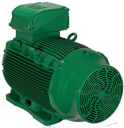
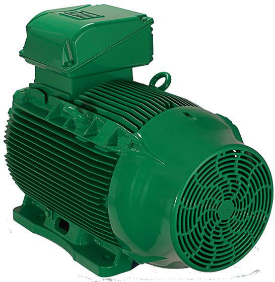

Newcomers to the pump industry are often unfamiliar with many of the three phase motor starting techniques that employed “pre-semiconductor” technology. Surprise — most of them are still in use today and will probably be here for some time to come. The primary purpose of alternative starting techniques is to reduce the system loading during starting. The typical AC induction motor has an inrush current during starting that is about five to seven times that of run current. Today, the VFD can provide a soft start and stop automatically just by ramping the input frequency. In the past, it was not always that easy. This article will review the most common methods of motor starting. A table at the very end will compare the electrical characteristics of each.
Before we get started, let's review how a typical six lead, three phase motor’s windings are connected to incoming power. The six lead stator is easiest to grasp and understanding how it is wired is important to our discussion of several starting techniques. Single voltage motors can be designed for either Wye (Y) or Delta connections. Dual (and tri) voltage motors are usually designed to utilise a Wye connection for high voltage and a Delta connection for low voltage. Figure 1 illustrates these two connection schemes.
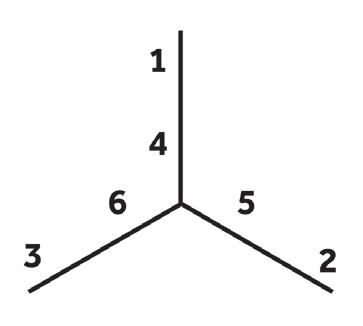

In the Wye connection (left hand figure), winding ends 4, 5 and 6 are joined together. Incoming power is connected to leads 1, 2 and 3 (the other end of the windings). In order for any two phases to connect electrically, they must traverse two sets of windings, thus increasing the impedance of the circuit.
In the Delta connection (right hand figure) winding ends 1 and 6, 2 and 4, and 3 and 5 are joined together. Incoming power is applied to each of these three pairs. Now any two phases may connect through a single winding. It is also common to find dual voltage motors wound for Y or Delta connection only. In this case, nine leads are required to establish the proper winding/voltage relationship.
The most common method of starting a motor is “across the line”. Here, a three pole switch or magnetic contactor connects line voltage directly to each of the motor leads. With this method, motor terminal voltage and current equals line voltage and current, and starting torque equals the motor’s rated starting torque. Figure 2 is a typical across the line starting schematic.

There are times, however, when it is desirable to reduce the current load required to start a motor, especially a large one. The following common, reduced current starting methods will accomplish this to varying degrees.
resistance reduced voltage starting
When series resistance starting is employed, a voltagedropping resistance is placed in series with the motor during starting. Figure 3 illustrates this technique. The resistance increases the overall impedance which causes a voltage drop. This method is used in low voltage (under 600V) applications where torque, during acceleration, is minimal. It is also limited to smaller motors since heat loss in the resistors can be a factor with larger models. There are instances where the motor cable alone can provide the necessary resistance during starting. Submersible pump motors that employ the maximum recommended length of a particular cable size can expect a five per cent voltage drop during starting. This will result in a nominal 16–20 per cent reduction in starting current.
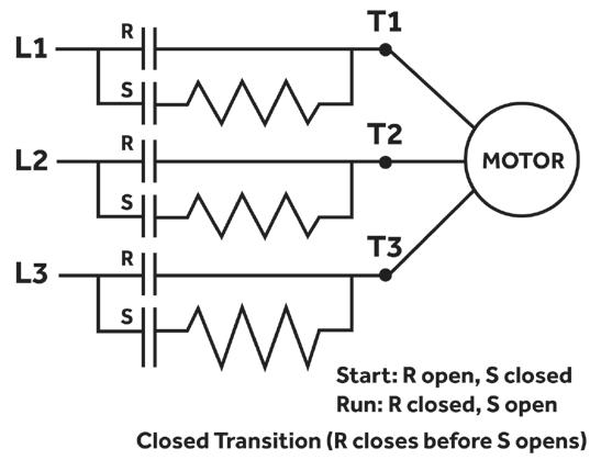
Series reactance reduced voltage starting
Figure 4 shows a starting method that is similar to the one above, except that a voltage dropping reactance is substituted for the resistance. Again, overall impedance is increased and the result is a voltage drop. Series reactance starting is used on medium voltage and large low voltage motors with minimal torque loading during acceleration.
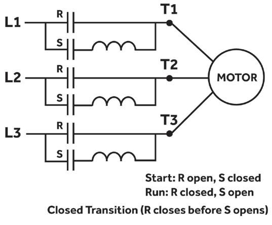
Autotransformer reduced voltage starting
In this form of reduced voltage starting, an autotransformer is placed in series with the motor. Its schematic is shown below. The transformer reduces the line voltage and thus reduces starting current. Starting current reduction depends on the voltage output of the transformer. Usually these devices are configured with an 80 per cent, 65 per cent and 50 per cent output tap. They are used where the required current reduction is substantial and load torque can be high.
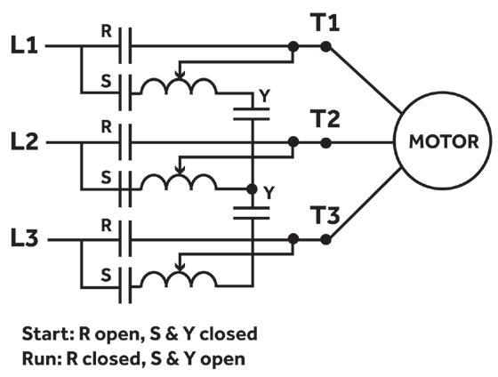
This form of reduced voltage starting uses a solid state starter that incorporates SCR’s (silicon controlled rectifiers). The SCR’s reduce the AC sine wave amplitude so that only a portion of the wave is seen by the motor. They are controlled by logic circuits that can respond to several different feedback sensors. Solid state starters are used when the rate of acceleration must
be controlled or when a “soft” start (reduced current) is desired. They are available for both low and medium (4160V) voltage motors.
Although sometimes confused with the method described above, variable frequency starting applies the full “effective” voltage to the motor terminals but at a reduced frequency via a variable frequency inverter. The initial

frequency can be very low and increased gradually. It is often used when full load torque is required during acceleration. They are usually too expensive to be used just as a starter, but can be justified at times because they offer the very best starting characteristics relative to the burden placed on the power supply. So far, we have discussed starting techniques that utilise devices that are totally separate from the motor. There are, however, several methods that can reduce starting current by changing the motor’s winding configuration.
Technically this is not a reduced voltage technique in that the motor terminals see full voltage. The wye/ delta starter connects the motor’s leads in a wye configuration during starting thus increasing the circuit’s normal reactance. The result is a decrease in voltage reflected to the stator equal to √3. Thus the current draw is reduced to about 30 per cent of the normal starting current. Once the motor is running the starter switches the leads to a normal delta connection and full voltage is restored. This technique is used when very low starting torque is required and is seen more often in systems manufactured in Europe.
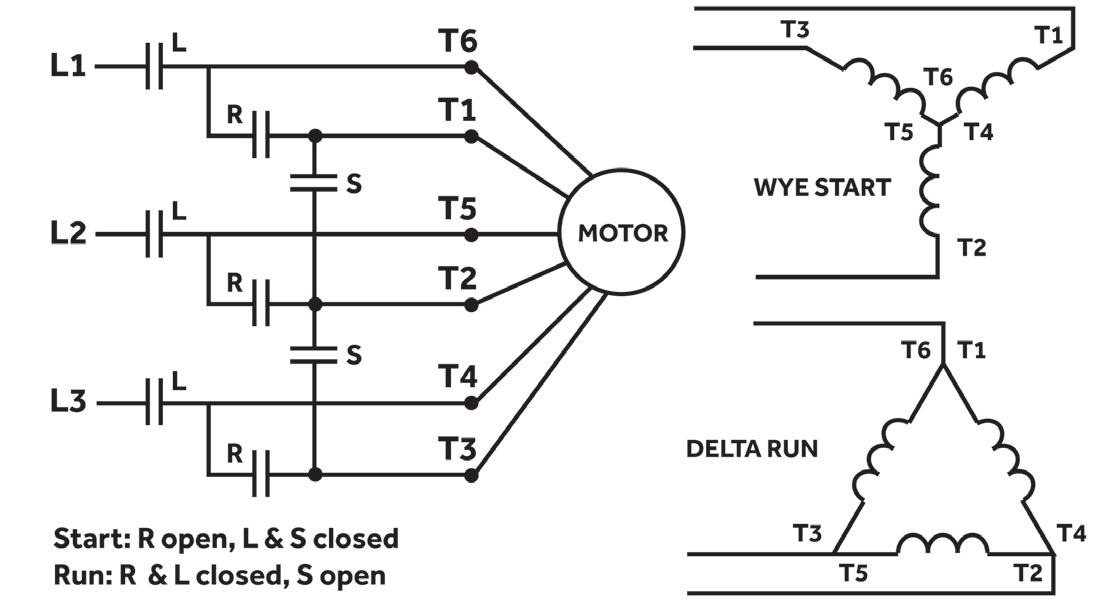
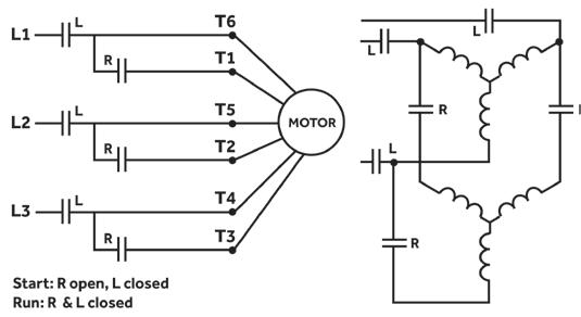
This starting method requires a motor wound specifically for this application. It is not a reduced voltage technique. These special nine lead motors use only a portion (1/2 to 2/3) of their windings during starting. Starting torque is extremely low and the motor is not expected to accelerate. Under some conditions, the shaft may not undergo visual rotation. In any case the starter should not remain in the start position for more that one to two seconds because of potential heat damage to the windings.
The starting methods described here apply to three phase, AC induction motors. There are other starting techniques for wound rotor AC motors and they will be discussed in a separate tutorial.
The table below summarises the electrical characteristics of the various starting techniques we have discussed.
Joe Evans has been in the pumps industry since 1986 and is passionate about the sharing of knowledge within the industry. To read more of his insights into the world of pumping, visit: www.pumped101.com
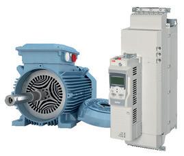
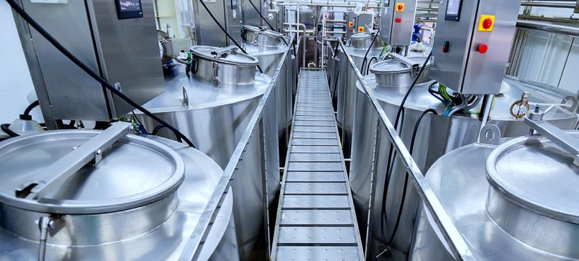
The idea is beautifully simple. Combine conventional stator technology and a magnet-free rotor design, take a top-of-the-line industrial drive and software, and optimize the whole package for variable speed pump and fan applications. What you get is the performance of a permanent magnet motor at IE4 efficiency and the simplicity and ease of service of a regular induction motor. Stop waiting and take a closer look on www.abbaustralia.com.au ABB Australia Pty Limited Contact Centre: 1800 222 435
TECO Electric and Machinery is a market leader, well-known for producing high-quality motors. Unsatisfied with producing only motors, TECO committed to the manufacture of motor drives over 20 years ago. In 2016, the company launched the TECO MV510 range of medium and high voltage drives that showcases its manufacturing prowess.
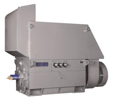
Founded in 1956 for motor production, TECO Electric & Machinery Co has evolved into a major business group spanning heavy electric equipment, home appliances, information technology, communications, key electronic components and parts, infrastructural engineering, financial investment, dining, and services, with its business scope covering over 100 cities in more than 80 countries in the five major continents.
In the future, in addition to continuing profound cultivation of its core businesses, TECO will develop in the direction of businesses with high added value, such as smart products and systematic solutions and dedicate to the expansion of hi-tech businesses, with the objective of "energy conservation, emissions reduction, intelligence and automation," in order to build up a macro-perspective and high-quality world-class brand.
TECO drives and motors are used in a variety of applications including industrial automation, industrial machinery, air conditioning systems, mining, oil and gas, energy-saving projects, pipelines and wastewater treatment.
Its MV510 range of drives is in compliance with global specifications for energy efficiency and environmental protection. The comprehensive portfolio
ranges from 200–8000kW, boasts power-unit connection overlapped-wave technology, and is capable of lowering damage to the insulated stress of a motors copper wire dv/dt and providing timely monitoring of operational status.
Options of IP31 and IP42 grade protections are available, plus RS485 interface, various communications formats — such as Modbus, Profibus, Devicenet, and Ethernet — and passage of CE and IEC certifications.

The power supply input and output of MV510 general medium voltage drive meet the most stringent IEEE 519 1992 and GB/T14549 1993 standards, so there is no need for an independent input filter, saving customers the cost for harmonic elimination.
Because of the high power factor of the system, the compensation device for power factor is not needed, thus the reactive input and the input capacity are reduced, and the cost for capacity increasing the power network is minimised.
Compared with other high voltage and high power MVDs, the MV510 has a number of significant advantages. Firstly, there is no need for extra output filtering devices or direct driving of the general high voltage synchronous or asynchronous motor, and the temperature of the motor will not increase. There is also no need for motor derating operation, and no dv/ dt damage will occur to the motor and cable insulation.

Due to the modular design of the power cell, it is quite simple to replace it and moreover, only a few spare parts are necessary. The power cells are universal and can be used in drives of the same current rating, regardless of voltage class.
Other functions and features include:
• Protection of overload and overcurrent
• Protection of open phase and grounding
• Protection of overvoltage
• Overheat protection
• Current limited function
• Interlock protection of control power supply
• Two sets of control power for redundancy power cell bypass function (optional)
• Cabinet door opening alarm function
• Lock-phase function
• Synchronising switch function between variable frequency and work frequency
• Soft start of motors, no impact to mechanical equipment and network
• IoT – Internet of Things With units already being sold, the TECO MV510 range of drives is making a significant contribution to the motor and drive market.

An overview of mechanical seal experience in the mining industry is conveniently obtained by examining sealing options and technologies found in the potash industry. Although this two-part article gives such an overview by delving into the business aspects of the potash industry, our approach serves as a reasonable template for other minerals retrieved by mining. After first giving a few highlights of what potash is all about, we will concentrate on the water saving aspects of sealing systems engineered to save both water and maintenance money.
Using potash today
The term potash dates back to antiquity and is derived from wood ash kept in metal pots. Pots were a commonly used storage method for this potassium-rich fertiliser. The term potash has carried over to a number of different mined and manufactured salts that contain “K” (for Kalium — a name derived from the arabic “Alkali”) in water soluble forms.
Over 14,000 different uses have been claimed for salt. As regards potash, we single out agriculture and all plant growth processes. In these processes, potash is a highly important nutrient. Today’s industrial scale fertiliser production depends on efficient large-scale potash mining operations. However, cost-saving efficiencies remain important in virtually every process operation that follows the initial rock mining or salt manufacturing steps.
Dilution by water not advantageous
Once mined, the rock has to be crushed and impurities must be removed. Saturated brine, which will not dissolve potash solids, is used to process the ore through a series of scrubbers to remove insoluble minerals. The introduction of plain water into a post-crushing stage would dissolve potash solids and thereby reduce the potash yield. Therefore, cost-conscious plant operators want to prevent flush fluids from entering the process through “standard” mechanical seals in their centrifugal pumps.
Water entry location and usage rate are known
Each gallon of water added to the process dissolves approximately 0.453kg (one pound) of potash. In general, the point of entry for water is the packing box (or seal housing) on the process pump. The packing box is located behind the pump impeller — the location where the rotating shaft meets the environment. With inadequate sealing strategies, seal water will either leak to the environment or into the process. Neither leakage path is desirable.
Pump feed capacities through the scrubbers and the floatation circuit are typically rated between 1000 to 2000 gallons per minute (GPM). For this capacity, the slurry pump manufacturer specifies a water flush of 14 to 16 GPM and, conservatively, one third of this flush directly enters into the process. Using a potash market price estimation of US$500/ tonne; the flush water entering the process through the pump

results in potash losses of US$613,200 per year.
Fortunately, this process flush water practice does not have to remain a cost burden; water entry can be eliminated using an alternative seal arrangement. The conversion cost estimate for this alternative is less than US$20,000, which provides a highly attractive return on investment of just 12 days. In order to optimise performance, it is essential to combine the correct mechanical seal design with a stuffing box design that prevents clogging and erosion. The issue is addressed and the problem solved by connecting the seal to a suitable off-the-shelf water management system.
This two-part article provides guidance on the selection variables relating to available water management systems. Particular emphasis is given to application experience that best highlights the business case.
A major seal manufacturer has worked with a well-known mining pump manufacturer for many years. At that time, the seal and system solution which is detailed here was installed at a corporation based in New Mexico, US. The paragraphs that follow make reference to this and other successful applications.
In a brine flotation tower service, three mining pumps continue to run after accruing an estimated 22,500 operating hours. Used in conjunction with a suitably selected mechanical seal, the seal support system shown in Figure 1 resulted in flush elimination of 6 GPM, or 360 GPH. For the three pumps involved in this service, 360 GPH equated to water savings of 8.1 million gallons per year. A second pump is shown in Figure 2; it uses a five-inch cartridge-style dual mechanical seal (CDPH, see Figure 3). Potash recovery savings were 4050 tonnes. At a market price of US$500/ton, this potash producer will have saved US$2,025 million.
Sealing options are largely influenced by long-standing industry conventions. Slurry pump manufacturers recommend expellers (or repellers), mechanical packing or single mechanical seals on slurry pumps. Whenever any of these three arrangements are used to seal the process pumps in the mine’s scrubber and floatation circuits, the manufacturer

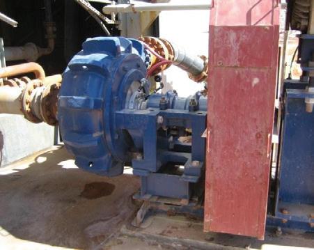
requires a clean water external water flush to be injected into the pump stuffing box. The American Petroleum Institute (API) piping plan 32 is the industry standard.
Figure 4 depicts a water line from an external water source connected to the back of the pump process at the packing/ seal chamber. This is where the rotating shaft exits the process casing and is a sealing point. Pump manufacturers specify the seal water to be injected at 10 psi above the discharge pressure of the pump. The water enters the volute casing in the stuffing box, directly behind the impeller. About one third, or more, of the flush water enters into the process stream because it is entering at a higher pressure. The remaining two thirds of the flush water leaks to the floor area surrounding the pump. If there is little outward leakage, a greater portion of the flush water entering the process fluid. This inward leakage dissolves the potash and reduces potash production yield, as outlined above.
Expellers (dynamic seals) force fluid back into the pump volute during operation. A set of packing rings or lips seals behind the expeller seal and the shaft in intermittent service. The expeller is limited by the pump inlet pressure. One
By Vendor By Purchaser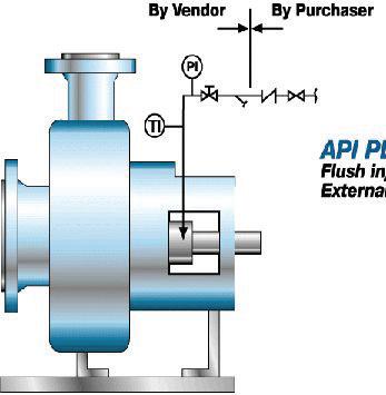
API PLAN NO.32
Flush injected from an External Source.
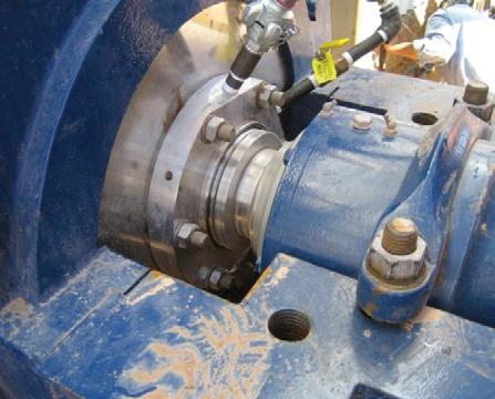
manufacturer recommends the maximum inlet pressure on a 1500 GPM application should not exceed nine psi to achieve leak-free performance. This means the expeller option is not suitable for high-pressure tailings pumps, for example, and leads to the mechanical seal selection option.
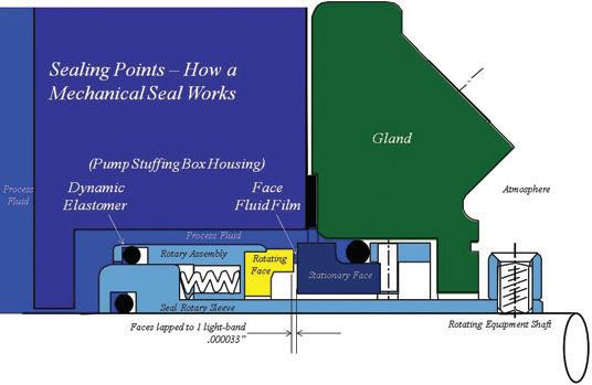
5: An O-ring seals the shaft, a dynamic elastomer accommodates axial motion of the rotary assembly, a gasket seals the housing, and the rotary face (in yellow) seals against the stationary face (in dark blue).
Single mechanical seals (Figure 5) are specially designed for slurry operation. In order to understand the rationale behind double mechanical seals, consider the sealing points in a standard cartridge mechanical seal. Figure 5 shows where an O-ring seals the shaft, a dynamic elastomer accommodates axial motion of the rotary assembly, a gasket seals the housing and the rotary face (in yellow) seals against the stationary face (in dark blue).
A fluid film between the two seal faces (or surfaces) creates the seal between the rotation of the shaft and the stationary housing of the rotating equipment. If this fluid film is not controlled consistently, the faces will leak. As slurry builds up on the atmosphere side under the seal stationary face, additional wear and damage is likely to occur.
Special slurry single seals (Figure 6) are designed with the idea of “grinding” the slurry between the seal faces. As they leak, wider clearance may be used to wash away leakage. Single slurry sealing is fine in theory. However, we want to think through what happens if the pump runs dry, or the pump suction filter clogs, or the suction lift is not immediately flooding the pump upon start up. Under these real-life scenarios, seal performance is limited. It doesn’t matter then if one uses mechanical packing, an expeller/


Figure 6: The slurry makes contact with the inboard portion of a double (“dual”) mechanical seal. The outboard portion (not shown) is making contact with a clean buffer fluid (blue). Due to an incorrect differential pressure, slurry has entered the face gap in this seal.
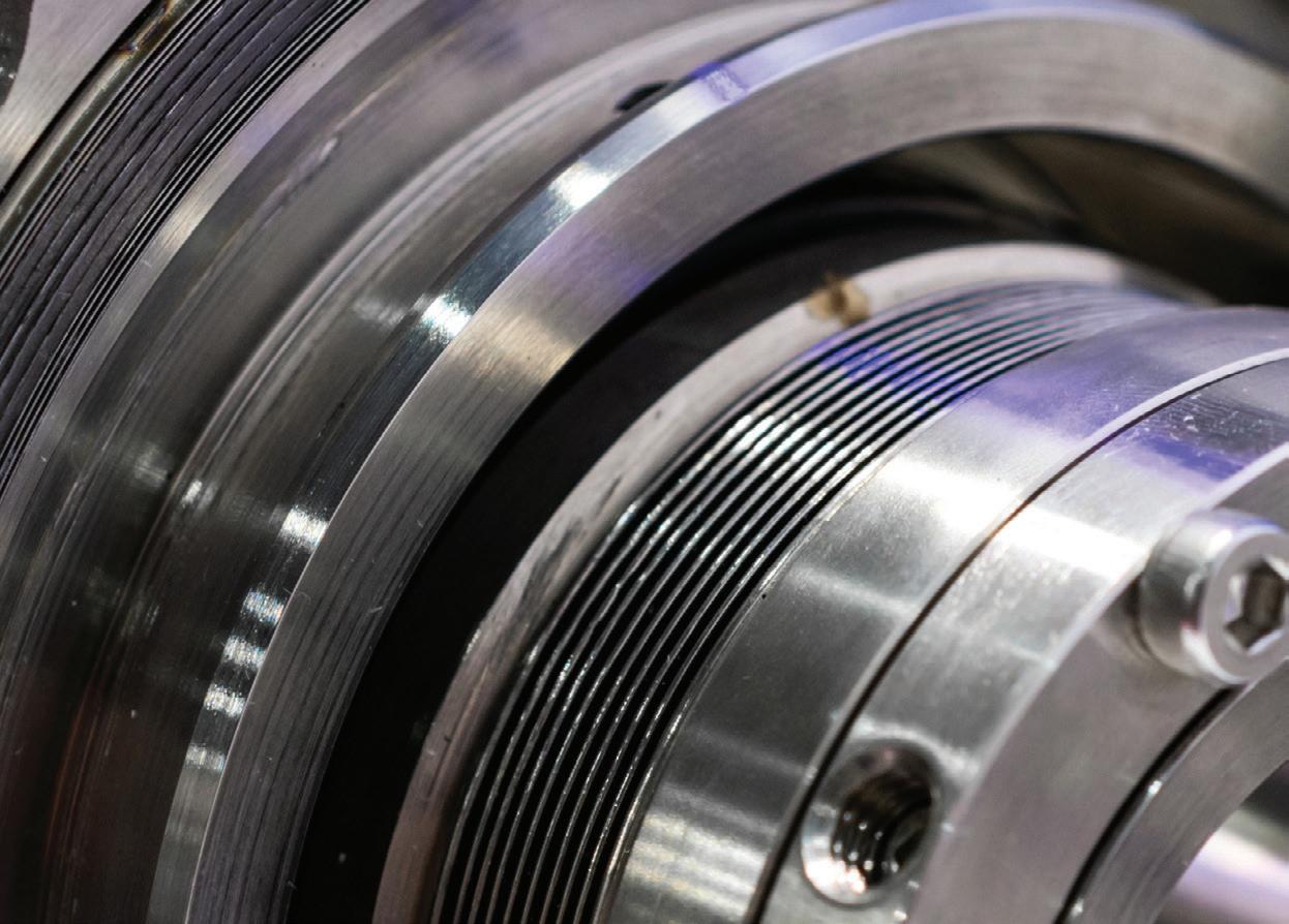
repeller or a single slurry seal — the fluid machine will fail.
So, there must be a better way to seal slurry pumps at reliability-focused user sites. This is why the application solutions to which we refer in this article all use dual mechanical seals. As a cautionary note, there are other variables that must be addressed beyond just installing a dual seal into the pump.
A highly experienced seal manufacturer recommends the use of dual cartridge mechanical seals and a support system to control the fluid film at the seal faces. Fluid film stability can be achieved and controlled when the barrier fluid pressure is greater than the seal chamber pressure. The fluid film is controlled by the differential pressure between the barrier fluid and the process fluid.
In Figure 6, process slurry is at a higher pressure than the barrier fluid. In this instance, the slurry (shown in brown) is forced into the face gap where only a clean fluid will do. Forcing slurry into the gap is not ideal; eventually the slurry will grind itself into the seal faces and the faces will no longer retain sufficient face flatness to maintain a seal.
With the correct pressure controls in a double mechanical seal, the clean barrier fluid is at a higher pressure and it is forced across the seal faces. From closely observing the film between the rotary face (in yellow) and the stationary face (dark blue), one notes the clean blue color barrier fluid (Figure 7).
Centrifugal pumps now available from
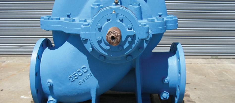
Emtivac’s range of centrifugal pumps meet ISO 2855/5199, API 610 11th edition and API 685 standards, and are manufactured and supplied to IS0 9001 standards.
The range features:
• Close coupled
• Long coupled
• Baseplate mounted
• Multi stage
• Split case
• Centre mounted
• Vertical
• Mag drive
• Mixed flow
With 30 years’ experience supplying vacuum and centrifugal pumps for various industries in Australia, Emtivac is your trusted solutions provider to help you maintain and improve your overall efficiency.


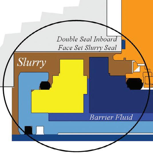
Figure 7: The slurry makes contact with the inboard portion of a double (dual) mechanical seal. However, with the correct differential pressure between a clean barrier fluid (blue), only the clean fluid is found in the seal gap.
If the seal face fluid film can be stabilised to ensure longterm reliability, the next technical point to address is how to minimise the wear on the seal components exposed to the slurry. This is done by selecting a seal chamber configuration that minimises erosion of the seal parts. It also involves a decision process between using standard ANSI type mechanical seals in light slurries and heavy duty thick cross section parts in heavy slurries. Part 2 of this article, to be featured in the Winter edition of Pump Industry magazine, addresses the issue.
Heinz P. Bloch resides in Westminster, Colorado. His professional career commenced in 1962 and included long-term assignments as Exxcon Chemical’s Regional Machinery Specialist for the US. He has authored or co-written close to 700 publications, among them 20 comprehensive books on practical machinery management, failure analysis, failure avoidance, compressors, steam turbines, pumps, oil mist lubrication and practical lubrication for industry.
Mr Bloch holds B.S. and M.S. degrees (cum laude) in Mechanical Engineering. He is an ASME Life Fellow and was awarded lifetime registration as a Professional Engineer in New Jersey.
Tom Grove was the founding startup officer of the US Subsidiary of AESSEAL Inc. and is currently its CEO.


A heating, ventilation and air conditioning (HVAC) piping system is designed to convey a heat transfer fluid to multiple air handlers, providing cooling (chilled water) or heating (hydronic heating) loads in a building. A typical HVAC system consists of a primary loop and a secondary loop. The primary loop contains the chiller or boiler along with primary circulating pump(s). The secondary loop draws fluid from the primary loop and consists of a secondary pump along with the supply header piping, various air handlers and return header piping. The primary and secondary loops are connected, so fluid mixes between the loops.
The key to designing an HVAC circulating water system is to control the flow rates to the various air handlers in order to maintain the temperature in the conditioned spaces. There are two types of methods to achieve this goal: one is a constant volume system, the other a variable demand system. In this analysis, you will learn how to achieve significant cost savings by using a variable demand system versus the more traditional constant volume system.
Before you design a new system, or make major modifications to an existing piping system, it is a good idea to create a computerised hydraulic model of the HVAC piping system. Piping software can provide the information needed to properly select the pumps and control valves. In addition, the computer model provides a good understanding of the interaction of pumps, pipelines and control valves.
The information from the computerised model can also be used to perform an economic analysis of pumping costs for both types of control systems. Image 1 is a rendering of a modelled HVAC system.
To perform this analysis, look at the differences between constant volume control and variable demand control, and perform a pumping cost analysis for each.
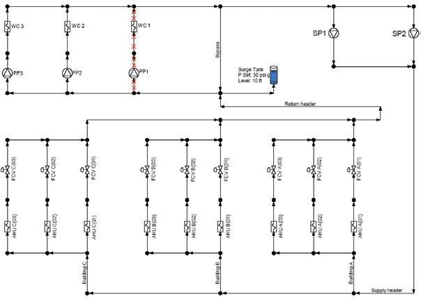
Under constant volume control for the piping layout in Image 1, both secondary pumps are operating just over 660 gallons per minute (GPM). Since this is a constant volume system, both pumps will be running constantly at this flow rate year-round. To keep the volume constant, some flow will go through the air handlers, and the remainder will go through a bypass line.
In a variable demand system, the flow rates to the loads vary based on the required heating or cooling needs. The first requirement is to estimate the required flow rates. They are based on the heating or air conditioning loads and may vary by the time of year and time of day.
In this analysis, it has been assumed that the average flow requirements in the winter months will be 30 per cent of the maximum design flow, spring and fall is 45 per cent of the maximum, and in the summer the design flow is 85 per cent of the maximum. It is important to note that the maximum design load is based on the needs for the hottest or coldest day of the year.
In this example for this project in the Pacific Northwest, the yearly pumping costs for the system was an energy rate of US8 cents per kilowatt hour (kWh). This should provide a conservative estimate elsewhere of costs as the national average is close to 13 cents per kWh.

Notice that the operating costs for pumps SP1 and SP2 are $10,012 and $10,062. Together, the operating cost for the secondary pumps running at a constant volume and fixed speed is $20,074.

The variable demand costs are slightly more complicated as the loads will vary more throughout the year. Here, we are using the flow rates mentioned above and considering summer, winter, spring and fall to each account for 25 per cent of the year. The spring and fall demands here are the same so they have been combined for a total of 50 per cent of the year.

The first important note here is that the system is capable of meeting the demands year-round using only one secondary pump. The operating costs for this secondary pump are $3080 in the summer, $140 in the winter and $560 in the combined spring and fall seasons for a total of $3780 for the year.
This annual operating cost for the secondary pumps is significantly less than the cost associated with the constant demand system. It is important to note that the reduction in pumping cost can only be brought about by installing a variable frequency drive (VFD). It is also important to factor in the cost of the VFD in your lifecycle pumping cost calculations.
The constant volume system is the more traditional method in which the system is balanced, such that a constant volume of fluid is flowing to each air handler regardless of the load. The piping to the air handler consists of a three-way valve that directs flow to the air handler or to a bypass line (Image 4).
In a constant volume system, the combined flow in the bypass line and to the air handler is constant, regardless of the flow rate to the air handler. A three-way valve directs the fluid through the bypass line, unless there is a demand on the air handler. When a demand is placed on the air handler, the three-way valve is repositioned to send some fluid to the air handler and less fluid through the bypass line. When there is no longer a demand by the air handler, the three-way valve redirects the flow through the bypass line.
The major advantage of the constant volume design is that once the system is balanced, by setting the design flow rate to each load, the control system is very stable. The threeway valve is able to direct the flow to the air handler without affecting the total flow rate through the system.
The major disadvantage to the constant volume system is the flow rates to each air handler are the same year-round regardless of the system’s heating or cooling load. In other words, in an HVAC chilled water system, the flow rate through the secondary loop is the same for the coldest day of winter as it is for the hottest day of summer. Therefore, constant volume systems typically have a higher operating cost because the flow rate through the secondary system is the same regardless of the system load.
Now that energy costs are higher, variable demand systems are becoming more popular. On a variable demand system, the three-way valve and bypass line are replaced with a pressure reducer and control valve in series to regulate flow to the air handler (Image 5). As the control valves in the other loads regulate the flow rate through the various paths, the differential pressures across the control valve can vary considerably. The wide variation of differential pressure across the control valves due to changes in system loads could cause problems with the control valve.
To overcome this problem, a pressure regulator is placed upstream of the flow control valve to absorb some of the excess differential pressure between the supply header and return header. The job of the pressure regulator is to reduce the pressure drop across the control valve. A smaller valve actuator can then be used so that a finer control can be achieved.

By installing a variable speed drive and controlling the pump’s speed based on the differential pressure across the various control valves, the pump produces less head for the same flow rate. This results in a lower differential pressure across the pressure regulator. Since the pump head is less, the pump consumes less energy, resulting in further savings in pumping cost.
Using a variable demand system saves on the operating cost because the flow rate through the system varies to meet the needs of the system demands rather than maintaining a constant system flow rate.
Greater pumping cost savings can be achieved on a variable demand system by adding a VFD on the pump. As mentioned previously, a pressure regulator is typically placed upstream of the control valve to limit the maximum differential pressure across the control valve. That is because as the flow rates in the other paths decrease, the pump moves back on its pump curve and provides a greater differential pressure across the pump. This results in a greater differential pressure across the supply and return headers. The job of the pressure regulator is to absorb some of the excess differential pressure so that the control valve can operate properly.
It is important to remember that there needs to be a minimum differential pressure across each control valve for the valve to operate properly. The purpose of the variable speed drive is to slow down the pump to provide only sufficient head needed for the control valves to operate properly. There is usually one control valve in the system that has the lowest differential pressure, and this is referred to as the most hydraulically remote control valve. A differential pressure sensor can be installed across the most hydraulically remote control valve to control the pump speed.
One additional point to remember; based on the various load combinations to the air handlers, the most hydraulically remote control valve in the system can change. Therefore, additional differential pressure sensors may be needed, resulting in additional instrumentation.
Since there may be many loads in a large HVAC system, it can become cost-prohibitive to insert differential pressure instrumentation on each control valve in the system. It is more cost-effective to install the differential pressure controls only on the valves in the system that have the possibility of the lowest pressure drop. This requires a thorough understanding of the HVAC piping system.




Located on the western edge of the Sydney CBD, Barangaroo is the largest urban renewal project to take place in the city since the 2000 Olympics and is one of the most significant waterfront transformations currently underway in the world. With sustainability the key focus for the development, architects and developers have incorporated smart building design to ensure higher performance and efficiency than regular developments. One of the ways this has occurred is by constructing a 77,000sqm basement beneath the Barangaroo South precinct to hide the building services.
Barangaroo spans 22 hectares along the Sydney harbour and is split into three development areas: Barangaroo South, Barangaroo Reserve and Central Barangaroo.
In December 2009, Lendlease was selected by the Barangaroo Delivery Authority to develop the Barangaroo South precinct, which covers the southern 7.5 hectares of Barangaroo. It will become home to around 1800 residents and 23,000 office workers, and is expected to attract around 18 million visits per year. The estimated end development value is $8.7 billion.
Formerly a container wharf, the site has been closed off for generations, but a world-class team of Australian and international architects are changing that, with over half the site and the entire 2.2km foreshore to become publicly accessible.
Once the precinct is complete, it is set to be the greenest and most advanced financial district in Australia, with the most sustainable buildings in the world, and will have a mix of uses, including commercial, retail and dining, as well as a new hotel.
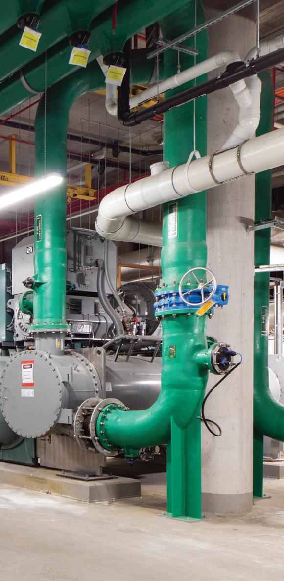
Hiding underneath the Barangaroo South precinct lies a 77,000sqm basement, designed to allow the area to maximise sustainability outcomes while reducing costs. This basement contains everything from a cooling plant to water treatment facilities, and is a prime example of how to implement less obstructive utility rooms.
James Peterson, Head of Operations for Barangaroo South – Lendlease, was part of a diverse design, development and construction team responsible for bringing the basement to life.
“We wanted to create something that was an example of global operational best practice in terms of its ability to leverage scale to run more efficiently, and removing duplication, whilst creating an exciting place for people to live, work and play,” Mr Peterson said.
“Most large commercial buildings around the CBD have poor ground planes because they have to house plant rooms, driveways, loading dock entries and exits, which leaves room for only a coffee shop or two at best. At Barangaroo we’ve
taken the plant, access ways, services and systems required for nine buildings into one basement with just two entry points.”
There are hudreds of rooms in the basement servicing security, cleaning, plant and pump operations, and retail.
Two of the major utilities located in the basement are a district cooling plant and a recycled water treatment plant.
Air conditioning systems in commercial buildings typically rely on cooling towers located on the roof. These consume an average of approximately 20,000 litres of water per day.
Peter Flynn, Development Manager, Infrastructure, Barangaroo South - Lendlease, said, “At Barangaroo, we utilised the scale and location of the area — on Sydney Harbour — to develop a ‘harbour heat rejection system’ for the central district cooling plant (DCP) in the basement.
“Using harbour water saves the precinct about 100 million litres of water per year, while freeing up the rooftops for solar panels.
“While the DCP is composed of chillers similar to those used in other commercial buildings, it’s the plant’s considerable scale — ten large units and two smaller ones — that allows it to meet precinct-wide cooling loads.”
The chillers, which are arranged in counter flow pairs for added heat transfer efficiency, provide cooling to a primary chilled water loop operating at 4.5°C. This then reticulates cooling though the basement to energy transfer stations at each building. The cooling is transferred to secondary chilled water loops in each building via heat exchangers which also act as pressure breaks.
In turn, the chillers are cooled directly by water pumped through their condensers from the seawater pumping station.
The recycled water treatment plant is capable of creating more water than the precinct uses each day. All black and grey water is taken through mechanical and chemical process to convert used water into high-quality recycled water used for toilet flushing and irrigation.
“The recycled water plant is built on membrane bioreactors which use natural biological processes, including cultivated bacteria, to remove nutrients from the precinct’s sewer flows. The resulting water is disinfected and filtered for reuse,” Mr Flynn said.
“The plant has the capacity to treat all the sewer flows in the precinct, as well as additional sewage drawn from external mains. These flows can be treated to a standard suitable for toilet flushing and irrigation.
“With an ultimate capacity of more than a million litres a day, the plant can not only process water for use in the precinct, but also for use in neighbouring buildings. This means more recycled water could be exported than the potable water imported.”
With such a large-scale project, a great amount of equipment needed to be procured, including pumping systems.
“It would be many hundreds. We buy pumps as parts of systems, rather than on their own,” Mr Flynn said.
“There was not one simple process for procuring the pumping equipment. Some elements came as part of system-based packages, others via installation subcontractors and the rest are purchased directly.
“Procurement decisions are based on the best risk mitigation and commercial considerations. We always assess the application, including whether it’s specialised, if there are suppliers with experience in this application and the technical risk associated with the application.
Mr Flynn said there were three crucial factors when selecting the pumps: they needed to meet minimum duty requirements, minimum efficiency requirements, and have a positive track record of operation in similar technical applications. After those criteria are met, cost comes into play.
Energy efficiency was also a key concern as the project aims to be awarded the highest available Green Star and NABERS ratings.
“Being part of a precinct aiming to be carbon neutral, the energy efficiency of the pumps was crucial. Almost all pumps in the precinct operate on variable speed drives to manage power draw. A minimum efficiency level is set for each specified pump, and these must be met to be part of the basement,” Mr Flynn said.
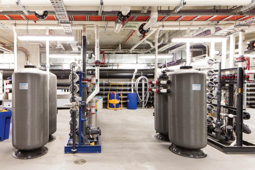
“Major pumps are tested off-site. All systems are commissioned on site. This typically includes verification of pump curves and maximum flow/head duty points where practical.”
Hiding services in the basement
Mr Flynn said given the scale of the basement, which includes a two-level dock for trucks, it provides much better accessibility to the pumps, and other equipment and facilities than a typical CBD building.
“Prior to construction, detailed studies were undertaken for the logistics of major equipment installation and replacement to ensure the larger items could be moved to their final location.”
Other facilities located in the Barangaroo South basement include a centralised security control room and operations room, loading dock, mailroom, and waste and recycling facilities.
The Barangaroo South project is expected to be completed in 2023.
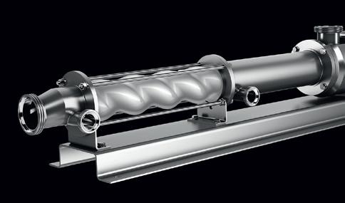
The EHEDG certified BCFH range of progressive cavity pumps handles thin to highly viscous products, including those containing soft solids with a low shear action and minimal pulsation which enables accurate flow control. BCFH pumps fulfill the stringent demands of cleanliness in the food, beverage, chemical, pharmaceutical and cosmetic industries.
EHEDG Type EL Class 1 and 3-A Sanitary Standards certified
Enhanced internal design ensures residue free cleaning with CIP/SIP
Equipment requires less cleaning time compared to other CIP solutions
Easy maintenance due to detachable rotor connection and split suction casing


A few years ago, after a FPAA fire conference where the topic of the session was compliance of fire pumps to the standard, a stationary fire pumps manufacturer made the statement, “It’s great to have a fire pump standard, but we have to compete in the market”. Sure all equipment suppliers need to compete in a market, but where standards and regulations should be conformed to, then they should be.
Self-regulation just does not appear to be providing complying outcomes.
What engineering principles could be simpler than a centrifugal pump, an electric motor or diesel driver, auto controller and some pipework? There is a quite specific standard — AS2941 — to follow for the equipment required to be installed in a fire pump installation.
Is it misinterpretation of the standard, lack of sound engineering knowledge or product knowledge of the various elements of a pump system?
Unfortunately deliberate misinterpretation, ignorance and deliberate short cuts occur regularly. The photos accompanying this article illustrate this.
The recent events of building fires both here and abroad illustrate and confirm that fire related standards are not always met. Someone has signed off and certified compliance with relevant fire standards and regulations yet non-compliance is often most obvious to the experienced engineer.
The Pump Industry Australia has had concerns for many years that the fire pumps and their installations do not always conform to standard and regulation.
Under the NCC, all buildings must have fire protection in accordance with their classification and follow particular standards. Where sprinkler systems and or hydrant systems together with fire pumps are deemed necessary, then it is mandatory by law to comply with relevant standards. There are no excuses!
But much of the building industry appears to have very little appreciation of the requirements of fire pumps and their installation, in particular the Australian Standard AS2941 Australian Standard Fixed fire protection installations – Pumpset systems.
Without even entering the self-regulation of industry argument, the ignorance of AS2941 in the building industry appears apparent, and that is even before zeroing down to the fire pump assembly itself.
The foreword of AS2941 reads, “This standard sets out requirements for pumpset systems to suit various types of fire protection systems such that a reasonable degree of protection for life and property from fire may be achieved. These requirements are based on sound engineering principles, test data and field experience.”

Then who is responsible for ensuring compliance with AS2941?
We see it as:
1. Architects and builders:
Section 11 and Appendix D state clearances required around fire pumps for maintenance and replacement, and the basic requirements of a pump room
2. Mechanical and electrical engineers, and designers:
Section 2 Water Supplies, Section 3 Electrical and General Requirements including pipework, Section 4 Specific Requirements of the bare pump itself
3. Pumpset manufacturers:
Section 3, Section 8 electric motors and controllers, Section 9 diesel drivers and controllers, and finally Section 10 for shop testing and the certifying of conformance
4. Fire contactors:
Need an understanding of all sections
5. Certifiers:
All sections

“It’s great to have a fire pump standard but we have to compete in the market. “
Examining the photos, the non-conforming issues are numerous. To name a just a few: insufficient floor space between pumps, confined space, room subject to flooding, and a plastic sump with small electric sump pump to discharge wastewater. Architects, builders and engineering designers are responsible for this arrangement. The installation was certified as complying and is (hopefully) fully operational, protecting a commercial city building.
It is normally the fire pump manufacturer who is asked to carry out commissioning and warrant his scope of supply. He would be totally unaware of the pump room design until arriving at site to carry out commissioning work. And finally, pity upon the servicing fitter who is required to carry out routine monthly, six monthly and yearly servicing in accordance with AS1851

Whilst the pump siting and installation is of major importance, it is the pumpset manufacturer that carries the final burden of ensuring the pump will start when called upon to do so. Perhaps with the supply of the pump, there is the piece of paper Certificate of Conformance that reads, “This is to certify that the ABC pump company fire pump serial number 123 has been manufactured and tested in accordance with AS2941”. But is this sufficient to ensure compliance? In the opinion of many the answer is “no, it is not sufficient”. Self-certification has proven to be no guarantee of compliance. The PIA and a number of pump companies have developed AS2941 checklists in an effort to improve compliance. This document is available to all those organisations that should use it. While the document may assist in improving compliance it is rarely used by a truly independent third party.









Co-located with Organised by *Based on 10,327 unique visitors at NMW 2017. CAB Audited by Audited Media Association of Australia.
Free-to-attend expo & conference Register now at


The pump industry relies on expertise from a large and varied range of specialists, from experts in particular pump types to those with an intimate understanding of pump reliability; and from researchers who delve into the particulars of pump curves to experts in pump efficiency. To draw upon the wealth of expert knowledge the Australian pump industry has to offer, Pump Industry has established a panel of experts to answer all your pumping questions.
This edition of Ask an Expert will look at EHEDG certification for progressive cavity pumps.
Q: How serious are progressive cavity (PC) pump manufacturers about designing their hygienic pumps to comply with industry standards/ certifications?
A: This is something many PC pump manufacturers take very seriously — following ISO, 3-A Sanitary Standards and FDA guidelines, as well as EHEDG regulations.
European Hygienic Engineering and Design Group (EHEDG) is a global consortium of over 400 food process equipment manufacturers whose aim is to ensure the hygienic design of process equipment. EHEDG certification guarantees residue-free cleaning at a lower temperature, with lower chemical concentration and a shorter cleaning time than is normal for other CIP (Clean in Place) solutions used in the food industry.
EHEDG has made recent changes to the certification process with a more rigorous and transparent test. Certification is now only valid for five years and results are reviewed by
independent EHEDG inspectors, in addition to those that carried out the original tests.
To quickly respond to food industry demands for equipment that adheres to strict safety and hygiene requirements without compromising product quality, various PC pump manufacturers have already certified — or are recertifying — their hygienic pumps according to this new process.
This gives end users complete confidence and peace of mind that their equipment meets the highest possible
level of hygienic design. As well as giving end users peace of mind, equipment designed to this standard typically requires 76 per cent less cleaning time — saving water, detergent and energy.
Q: What other ways do hygienic progressive cavity (PC) pumps stand out against competitors?
A: Thanks to their low shear action, PC pumps do not affect a product’s physical quality; including even sensitive products such as yogurts, cream cheese, whipped cream or other colloidal mixes. Equally, they can efficiently pump
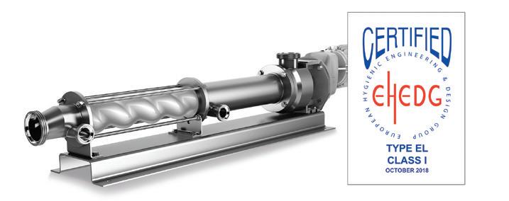
viscous and sticky products, as well as those containing soft solids such as fruit or vegetable pieces.
PC pumps help lower production costs because other alternatives — such as rotary lobe or twin screw pumps — create shear, which affects consistency. Additives are then needed to compensate for this shear to ensure that sensitive
products — such as yogurts — regain their original consistency. Food producers using low shear PC pumps do not need to pay out for such additives.
The unique design of hygienic PC pumps can include a special surface shape, dead-space free areas and other particular features to prevent product components from collecting. This
internal design allows complete flushing of all areas and optimal CIP/COP/SIP cleaning and sterilisation.
For more information on progressive cavity pumps, please contact SEEPEX Australia at (02) 4355 4500 or info.au@seepex.com.

Peter Vila, Managing Director of SEEPEX Australia, is a progressive cavity pump expert. He has been involved with pumps for over 35 years. Peter spent the first five years repairing pumps and the following 30 years in technical sales, 15 of which have been with SEEPEX progressive cavity pumps.
For more information on progressive cavity pumps, please contact SEEPEX Australia on (02) 4355 4500 or at info.au@seepex.com

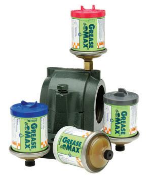

Australia’s largest manufacturing exhibition and conference returns in 2019, with the 20th edition of National Manufacturing Week to be held from 14–17 May at the Melbourne Convention and Exhibition Centre.
After a successful Melbourne event in 2017 with over 10,000 attendees, National Manufacturing Week 2019 will be about driving continuing innovation in local manufacturing, the evolution of advanced technology solutions, sharing insights to stay ahead of the game, and celebrating Australian manufacturing’s recent resurgence.
“National Manufacturing Week 2019 arrives on the industry’s calendar at a truly exciting time of growth in Australian manufacturing. This year’s event is focused on supporting manufacturing’s continuing evolution to a high-tech, highly integrated and innovative industry, while providing the latest expert insights, industry research and technology to generate even greater momentum,” said Robby Clark, Exhibition Director of National Manufacturing Week.
The focal point for the manufacturing community to come together, interact, connect, and be inspired will be ‘Industrial Evolution’. This theme for the 2019 National Manufacturing Week will feature across both the conference program and exhibition.
“Automation, collaborative robots, the Internet of Things and high-level engineering will be the prime focus at this year’s event, offering industry professionals and decisionmakers an unmissable opportunity to acquire new insights, and source innovative solutions for ongoing operational success,” Mr Clark revealed.
Strategic partners and industry associations supporting National Manufacturing Week in 2019 include the Advanced Manufacturing Growth Centre (AMGC), Innovative Manufacturing CRC (IMCRC), Engineers Australia and Weld Australia. These partners strengthen National Manufacturing Week’s industry relevance and cement the event’s status as the hub for the manufacturing community to come together and share insights to support continued growth in the industry.
This year’s exhibition floor will feature over 200 leading industrial suppliers of game-changing solutions, new technology, advanced manufacturing products and operational services.
Exhibiting suppliers who have already confirmed their presence for National Manufacturing Week 2019, include: WAGO, 3M Australia, Central Innovation, Universal Robots, Profifeed Technologies and Kobot Systems. A diverse number of first-time exhibitors are also joining the event this year, such as Partable XRF, ASG Group, and High Tech Products.
Visitors to National Manufacturing Week 2019 will be able to take advantage of six designated product zones to navigate through the exhibition floor, where the extensive range of products and solutions will be segmented into key operational categories. The six product zones for 2019 are: Automation and Robotics, Engineering, Industrial Internet of Things, Safety, Welding Technology and Manufacturing Solutions.
“We are excited to see the game-changing, innovative and high-tech solutions that our extensive exhibitor list is planning to showcase at National Manufacturing Week 2019, with numerous live demonstrations and practical applications already planned for the event,” said Mr Clark.
The increased collaboration between the Advanced Manufacturing Growth Centre, Austech and National Manufacturing Week, will see the 2019 conference program feature an impressive lineup of more than 70 expert speakers, who will share their exclusive insights about current industry challenges and recommendations for success.
Divided into the Industry 4.0 Theatre and Connected Manufacturing Theatre, these two conference streams will focus on the impact of Industry 4.0 to operations, and improving efficiency, safety and operational management.
During National Manufacturing Week 2019 there will be several networking and celebratory functions, including the National Manufacturing Week 20th Anniversary networking function, 2019 Victorian Manufacturing Hall of Fame Awards and Endeavour Awards.
National Manufacturing Week will again be co-located with Austech, the only metalworking, machine tools and ancillary market focused event in Australia.

When the pressure of flowing liquid drops to or below the liquid’s vapour pressure, the liquid boils and vapour cavities (bubbles) form locally inside the liquid. If the pressure within the flow path subsequently increases above the vapour pressure, the vapour cavities implode, releasing energy. The formation and sudden collapse of these “bubbles” is called cavitation.
The generation of head in a centrifugal pump does not commence until the liquid enters the vane area and is accelerated towards pump discharge. As the liquid flows between the pump inlet flange and vanes, several points of head loss occur due to:
• Friction in the suction nozzle
• Acceleration losses as the liquid velocity increases from the suction nozzle to the impeller eye
• Shock losses as the liquid contacts the leading edges of the impeller vanes
• The sum of these losses is known as the entry loss. If the suction head minus the entry loss reduce the liquid pressure to or below the vapour pressure, then a condition for cavitation exists
Some types of installations are more likely to incur cavitation than others. The presence of any of the following conditions, detailed below significantly increase the possibility of low NPSHA values and cavitation:
• High temperature or boiling liquids: This will increase the vapour pressure head
• Volatile liquids: These have a high vapour pressure head
• Suction tank under vacuum: This will reduce the absolute pressure head on the liquid surface
• High suction lift applications
• Circuitous suction pipework: This will lead to increased friction loss
• A high number of fittings in suction pipework: This will increase friction losses
Please consider this in your pump selections and if in doubt, discuss the matter with your pump supplier.
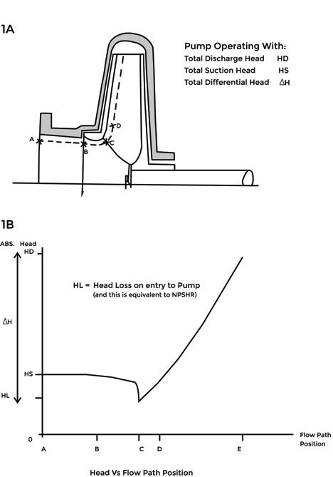
Figure 1 Flow path through a Centrifugal Pump


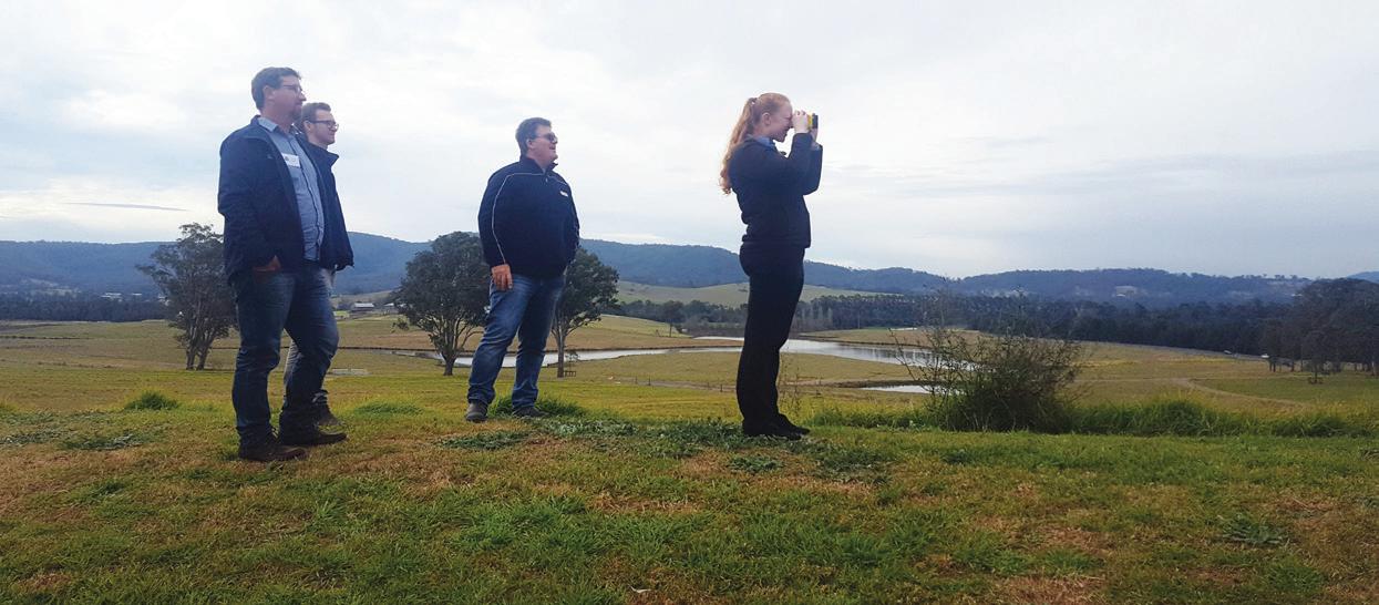


RANGE OF INDUSTRY TRAINING:
• Centre Pivot Lateral Move (2 days)
• Centre Pivot Lateral Move (2 days)
• Meter Validation and Installation (2 days)
• Meter Validation and Installation (2 days)
• Introduction to Irrigation (2 days)
• Introduction to Irrigation (2 days)
• Irrigation Efficiency
• Irrigation Efficiency
• Introduction to Irrigation - Urban & Agriculture
• Introduction to Irrigation - Urban & Agriculture
• Basics in Wiring & Electrical Troubleshooting
• Basics in Wiring & Electrical Troubleshooting
• Basics of Drip Irrigation
• Basics of Drip Irrigation
• Irricad Design Course
• Irricad Design Course
Our courses provide an in-depth irrigation training program which is assessed against nationally recognised Competencies towards Certificate III in Irrigation AHC32416. This training course will be presented by highly experienced and qualified professionals who are actively working in leading organisations of the industry. The program also engages subject matter experts for specialised topics such as hydraulics, troubleshooting and basic irrigation design, to name a few.
Our courses provide an in-depth irrigation training program which is assessed against nationally recognised Competencies towards Certificate III in Irrigation AHC32416. This training course will be presented by highly experienced and qualified professionals who are actively working in leading organisations of the industry. The program also engages subject matter experts for specialised topics such as hydraulics, troubleshooting and basic irrigation design, to name a few.
Learn the process of operating and maintaining irrigation pumping systems and be issued with a statement of attainment for the nationally recognised competency AHCIRG410A Select and Manage Pumping Systems for Irrigation. Designed for anyone working or seeking working in the selection & supply of irrigation pump systems including installation, commissioning, monitoring and operation.
Learn the process of operating and maintaining irrigation pumping systems and be issued with a statement of attainment for the nationally recognised competency AHCIRG410A Select and Manage Pumping Systems for Irrigation. Designed for anyone working or seeking working in the selection & supply of irrigation pump systems including installation, commissioning, monitoring and operation.
VISIT OUR WEBSITE FOR THE FULL TRAINING CALANDER
VISIT OUR WEBSITE FOR THE FULL TRAINING CALANDER
Meter Installation & Validation | 31 MAR -01 APR 2019 R ic hmond, N SW
Meter Installation & Validation | 31 MAR -01 APR 2019 R ic hmond, N SW
Meter Installation & Validation | 31 MAR -01 APR 2019
Meter Installation & Validation | 31 MAR -01 APR 2019
Certificate III in Irrigation | 07-10 MAY 2019
Certificate III in Irrigation | 07-10 MAY 2019
Certificate III in Irrigation | 07-10 MAY 2019
Certificate III in Irrigation | 07-10 MAY 2019
Meter Installation & Validation | 14-15 MAY 2 0 19
Meter Installation & Validation | 14-15 MAY 2 0 19
Centre Pivot & Lateral Move | 21-22 MAY 2 019
Centre Pivot & Lateral Move | 21-22 MAY 2 019
Irrigation Pumps & Systems | 25-26 JUN 20 19
Irrigation Pumps & Systems | 25-26 JUN 20 19
Adelaide, SA
Adelaide, SA
Perth, WA
Perth, WA
Melbourne, VIC
Melbourne, VIC
Mackay, QLD
Mackay, QLD
Narrabri, NSW Perth, WA
Narrabri, NSW
Perth, WA

Our pumps are standard with features like 50 SCFM vacuum mechanical diaphragm pump, our patented “posilock” valve which prevents carry over, NRV, and available in bare shaft or SAE mount with fly wheel coupling. Our standard off the shelf material of construction offering is ductile iron castings/hardened SS impeller/SS shaft and run-dry mechanical seal.
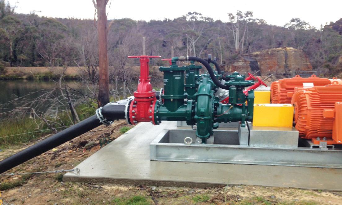
Leading-edge hydraulic engineering makes our centrifugal pumps the highest performing pumps on the market. Our pumps provide better flow, higher head, greater efficiency, and unparelleled service designed to meet your unique challenges.

pioneerpump.com/se-asia-pacific