POWERING HVAC with heat pumps
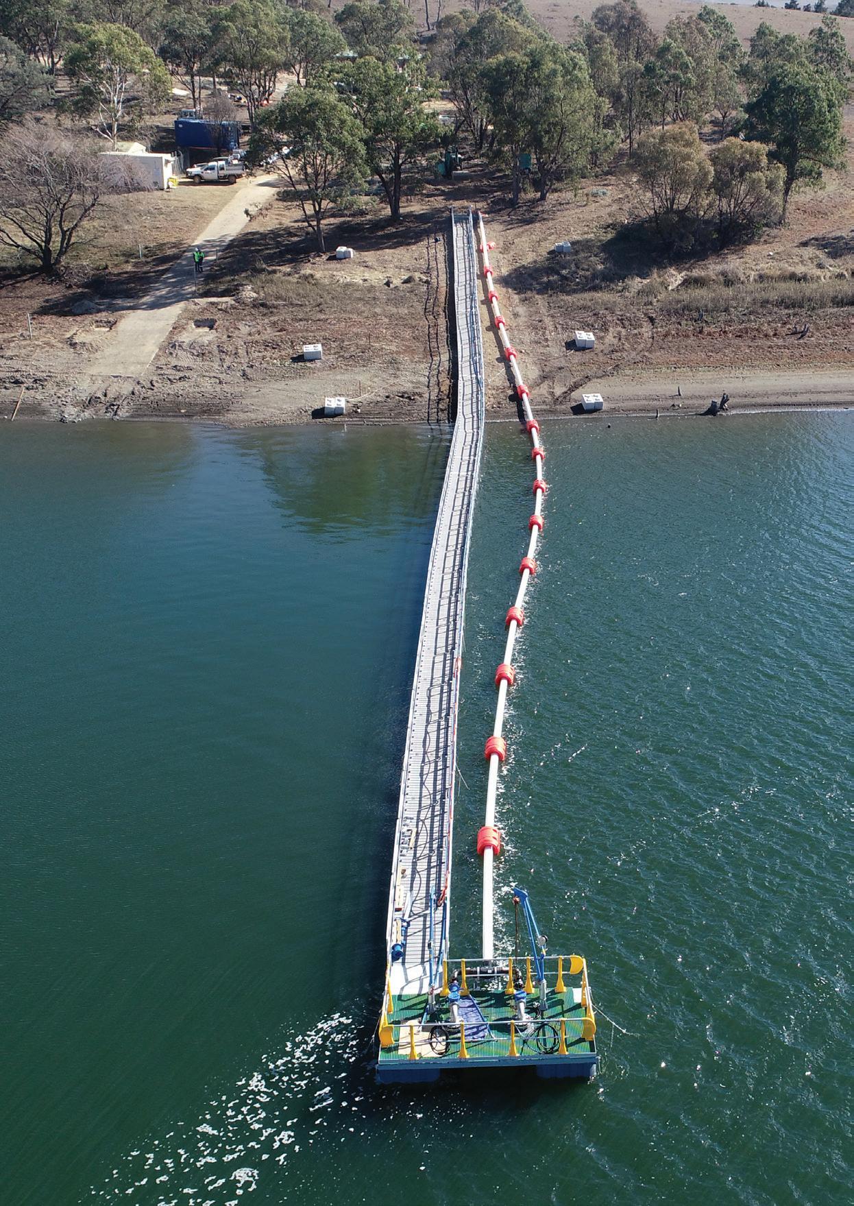
Floating pumps bring water to Guyra
Lubrication update for electric motors
ISSUE 31 AUTUMN 2020
pumpindustry
· POWERED OR SELF-PROPELLED
· INTERNAL AND EXTERNAL BRUSHES
· WEDGE WIRE SCREENING DOWN TO 1MM
· AUSTRALIAN MADE
·


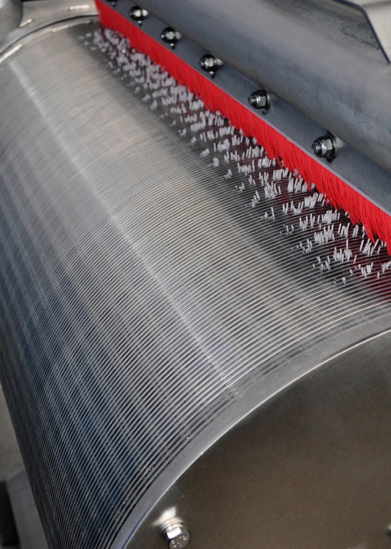
SELF-CLEANING PUMP INTAKE SCREENS
PURPOSE BUILT TO SUIT FLOW, CONFIGURATION AND ENVIRONMENT Phone 03 5456 3331 info@awmawatercontrol.com.au www.awmawatercontrol.com.au AUSTRALIAN MADE AWMA specialise in the design and manufacture of water control infrastructure including Penstocks, Stopboards, Flood Barriers and Screens.

all feature
quality,
reliability,
fuel-efficient
other products in
market.
canopy
made
galvanised
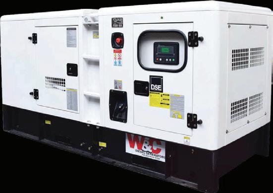
metal and can withstand exposure to the elements. Best of all, the sound proof system exceeds industry requirements.
more
contact your local Dealer. Stay powered with DEUTZ DEUTZ Australia | www.deutz.com.au | deutzoz@deutz.com The engine company.
Introducing our new heavy-duty Power Generators designed specifically to suit our region’s unique business and farm environment. They
the trademark DEUTZ world-class
performance and
and they are more
than
the
The
is
of
sheet
Discover
- www.deutz.com.au/gensets or

Pump Industry Australia Incorporated
PO Box 55, Stuarts Point NSW 2441 Australia
Ph/Fax: (02) 6569 0160 pumpsaustralia@bigpond.com
PIA Executive Council 2020
John Inkster – President Brown Brothers Engineers
James Blannin – Vice President Stevco Pumps & Seals
Kevin Wilson – Treasurer/Secretary Executive Officer
Alan Rowan – Councillor Executive Officer – Publications and Training, Life Member
Ken Kugler
Executive Officer – Standards, Life Member
Louise Black – Marketing and Statistics Executive Officer Envirotech Water Solutions
Geoff Harvey – Councillor Irrigation Australia Limited
Joel Neideck – Councillor TDA Pumps
Mike Bauer – Councillor DynaPumps
Steve Bosner – Councillor Pioneer Pumps
Hem Prakash – Councillor Davey Water Products
Anant Yuvarajah – Councillor ASC Water Tanks
Hello all and welcome to this edition of Pump Industry Magazine. It has been a tumultuous few months with the bushfires starting September 2019 exacerbating one of the worst droughts Australia has experienced, and then in early February the heavens opened and unleashed massive amounts of rain in a short period of time.
These events have imposed significant hardship on our farmers and rural communities who wear the brunt of the economic and social burden; they also presents challenges to the Australian economy. Tragically 29 people have lost their lives from the bushfires, both locals and firefighters alike, and some 2,000 homes have been destroyed; I am unsure of the number of livestock that have perished but have read estimates of some 140,000 cattle and sheep, and estimates that around 480 million animals have perished.
And then to top it off we had the Coronavirus coming out of Wuhan which at the time of writing has claimed over 3,800 lives and affected over 110,000 people primarily in China. Over 300 people have been diagnosed with Coronavirus here in Australia; sadly the number who have died is almost five times the number of people who died from the SARS epidemic in 2003. Like others, we in the pump industry are not immune from the knock-on effect as most of us are reliant on imported product and components; there is now a shortage of containers and vessel space, particularly for LCLs and congestion of ports. This situation is expected to remain for the next few months.
These events will inevitably impact on GDP with the bushfires estimated to impact 0.20 per cent and the drought 0.25-0.40 per cent. The Coronavirus has the potential to make an even greater impact, so some headwinds and tough times are ahead for the economy.
PIA has held one Breakfast Meeting this year on 19 February hosted by Cummins South Pacific in Melbourne. Unfortunately, in light of the Coronavirus, future Breakfast Meetings and other PIA events have been cancelled or postponed to ensure the safety of everyone.
Previously, I spoke of the collaboration between PIA and Irrigation Australia Ltd (IAL) to provide a ‘Pumps and Systems Training Course’ exclusively for PIA Members. This has now come to fruition with PIA now able to offer a threeday competency based course with a Nationally Recognised Certificate being provided upon completion.
The course will only be available through the PIA, with PIA responsible for marketing and location of suitable venues including test facilities; this is
currently being undertaken. IAL will provide access to the certification as an RTO and approved trainers.
Current thinking is that two courses will be held in 2020 in Melbourne and Brisbane.
So watch this space as we determine dates, venues and costs. The cost will cover all course materials, catering and assessment of the follow up work after completion; ideally, we are looking for a minimum of ten participants for the course.
Ken Kugler, our Standards Executive Officer, has advised that following our proposal to Standards Australia, draft standard AS/ISO ASME 14414 was issued in January. This standard has already been endorsed by Europe, Britain and the US, and should it be adopted here, will set procedural and competency benchmarks for the auditing of the energy consumed in pumping systems.
Also, the Commonwealth on behalf of the Equipment Energy Efficient (E3) Program is seeking views from stakeholders on issues with the regulation of three phase cage induction motors for efficiency in Australia and NZ. The Issues Paper – Energy Efficiency Regulation of Electric Motors canvasses issues that will define the scope of the changes to be considered in the Consultation Regulation Impact Statement – Electric Motors, which is expected to be published later this year. The request for information has been sent to interested members and to the electric motor manufacturers.
The incoming Council is actively canvassing for new members, with membership now standing at 89 with 92 per cent being fully paid up; we want to grow this to 100 members. There are two ways of joining PIA: sign up online on PIA’s website or complete the Membership Application Form and email to Secretary Kevin Wilson at pumpsaustralia@ bigpond.com. Visit pumps.asn.au for more information about becoming a member and all the benefits associated. By the time you receive this edition, we will be in the second quarter of 2020 and we will all have a clearer view of where the year is headed and whether or not the RBA responds by cutting the OCR further. The last cut was in September when the RBA cut the rate to an unprecedented low of 0.75 per cent amid concerns about the Australian economy. I look forward to seeing some of you at our upcoming events and can only urge you all to participate as we endeavour to strengthen PIA’s member base.
We seek your continued support and ideas.
John Inkster President
2 pump industry | Autumn 2020 | Issue 31 www.pumpindustry.com.au PRESIDENT’S WELCOME


Volvo Penta. Robust, fuel efficient industrial diesel engines that keep running even in the toughest conditions. Easy to install, operate and maintain. A powerful partnership you can trust all the way from the drawing board throughout the operational life of your engine. Competitively priced complete power-pack units ready for delivery Australia wide with a local support team on hand 24/7. To find your nearest dealer visit www.volvopenta.com 105-515 KW
A POWERFUL PARTNERSHIP


4,607
Published by Monkey Media Enterprises


ABN: 36 426 734 954
204/23–25 Gipps St
Collingwood VIC 3066
P: (03) 9988 4950
F: (03) 8456 6720
monkeymedia.com.au info@monkeymedia.com.au pumpindustry.com.au magazine@pumpindustry.com.au
Editor: Lauren Cella
Assistant Editor: Eliza Booth
Journalist: Luisa Romeo
Business Development Managers: Alastair Bryers, Rima Munafo
Design Manager: Alejandro Molano
Designers: Jacqueline Buckmaster, Rupa Anurenda
Publisher: Chris Bland
Managing Editor: Laura Harvey
ISSN: 2201-0270
PIA NEWS
PIA MEMBER NEWS
INDUSTRY NEWS
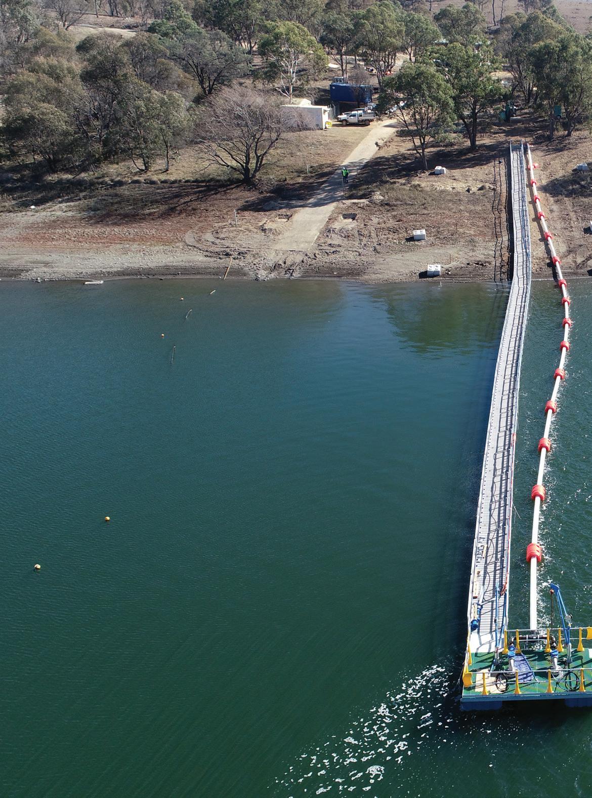
CONTENTS Cover image highlights our feature on water, showing the floating pontoon pump infrastructure installed by Armidale Regional Council. This magazine is published by Monkey Media in cooperation with the Pump Industry Australia Inc. (PIA). The views contained herein are not necessarily the views of either the publisher or the PIA. Neither the publisher nor the PIA takes responsibility for any claims made by advertisers. All communication should be directed to the publisher. The publisher welcomes contributions to the magazine. All contributions must comply with the publisher’s editorial policy which follows. By providing content to the publisher, you authorise the publisher to reproduce that content either in its original form, or edited, or combined with other content in any of its publications and in any format at the publisher's discretion. ISSUE 31 AUTUMN 2020 pumpindustry Floating pumps bring water to Guyra Lubrication update for electric motors POWERING HVAC with heat pumps NEWS Surviving disasters: how fires, floods and Coronavirus are impacting the pump industry ............................................................... 6 Santos solar powered oil well pumps project a success 8 Major pumping station and water intake contracts awarded 8 Government cracks down on payment of suppliers ................................. 9 Contract awarded for village water reticulation system designs 10 Pumped hydro project terminated ........................................................... 10 Innovative approach to give more water to Tasmanian irrigators 12
Getting up close and personal with engines at PIA’s Breakfast Meeting in Melbourne .............................................................. 14
New range of EN733 pumps: World-leading performance .................... 16 Sewer bypass system uses layflat hose 18
Monitoring remote pump infrastructure: Better, easier and cheaper using 4G 20 World’s harshest conditions create energy efficient pumps 22
This publication has been independently audited under the AMAA’s CAB Total Distribution Audit. Audit Period: 1 April 2019 to 30 September 2019

WATER


DRIVES
5 www.pumpindustry.com.au pump industry | Autumn 2020 | Issue 31 pumpindustry
Keeping the water flowing in Australia’s largest man-made conservation and recreation lake ............. 24 Top three benefits of VFDs for irrigation pumping 30 Floating pumps help boost water supply to Guyra ..... 32 Pumping up Dubbo's assets 36 Automated water treatment process for increased output and cost savings 40 Raising the energy efficiency standards of pool pumps .............................................. 42 MOTORS,
AND ENGINES Guaranteed control and maximum system efficiency .............................................................44 Lubrication update for electric motors ....................... 46 Industry 4.0: the implications for industrial motor control 50 The pumps helping NSW beat transmission losses 52 Not just motors: the high-reliability TECO MV510 VSD range .............................................. 55 Caprari presents the new EASYWELL MPC10 motor ................................................................ 56
Applying dynamic lift up-stream pumping (USP) sealing technology to slurry pumps ............................. 58 HVAC AND BUILDING SERVICES Powering HVAC with heat pumps 62 TECHNICAL Visualising a piping system 64 INDUSTRY VOICES Billie Tan 68 PUMP HANDBOOK Efficient operations of pump systems (Part 3) 72 REGULARS : President’s welcome 2 Ask an expert: Benfits of customised progressive cavity pumps in wastewater and sludge treatment applications ..........70 Pump school: Impeller trimming - noise changes (Part 3) ................ 74 Editorial schedule .......................................................... 76 Advertisers’ index 76
SEALS
SURVIVING DISASTERS: how fires, floods and Coronavirus are impacting the pump industry
By Eliza Booth, Assistant Editor, Pump Industry magazine
It’s been a turbulent start to 2020 for Australians, facing one disaster after another. Industries across the country are feeling the impact of these events –from devastating bushfires to damaging rainfall, all the way through to the latest threat of COVID-19.
Like most industries, pumps are not immune to the impacts of these events and as a result actions, precautions and future preparations are essential for companies to survive and thrive after these events.
Here we take a look at what has been going on in the industry over the past few months and how these events have affected the pump industry.
Fire
The 2019/20 bushfire season brought on the worst bushfire crisis the country has ever seen. During this time, not only was a lot of pumping infrastructure destroyed, but pumps also played an important role in assisting firefighters in their efforts to battle the blazes.
Pump suppliers and manufacturers stepped up and supported firefighting efforts with supplies, donations and technical expertise. With damage to a lot of pumps and associated infrastructure, there was an increase in demand for replacement equipment. This led to many pump suppliers running out of stock as demand sky-rocketed.
One pump supplier told Pump Industry that a lack of education around preparing for bushfires was a primary issue with customers and volunteers. The company said that education on which pump is right for the customers' needs and limitations was vital to ensuring the correct equipment was supplied so end users weren’t left vulnerable in the future.
In Armidale, rural and aerial firefighting efforts were given a boost with the help of a new bore which was established at the Armidale Airport. This bore supplemented efforts after weeks of firefighting exhausted water supplies in a local dam. The 114m-deep bore was fitted with a pump that could extract

water at 18,000L per hour, making a much needed backup water source available for firefighters.
On Kangaroo Island, one of the worst hit areas in the country, a water purification and desalination system was flown in by the Air Force to help supply drinking water to residents. The system worked by pumping water from the ocean and then removing salt and purifying it before being tested and distributed for consumption by residents.
As the fires were being brought under control, the Federal Government announced a $100 million bushfire support package for primary producers. This package helped producers purchase or hire immediate essentials like fodder, water, pumps, irrigation systems, generators and much more.
Floods
Following the driest and hottest year on record for Australia in 2019, the east coast was then lashed by devastating rainfall and hail at the beginning of February. While it brought much needed relief to fire-affected areas, it also caused wide-spread flooding and damage to parts of New South Wales, Queensland and the ACT.
However from this event, councils and companies across Australia looked to flood mitigation measures to help increase their resilience for future flood disasters.
Cairns Regional Council awarded a contract for its $3.3 million upgrade to the water intake infrastructure at Crystal Cascades, which supplies the Freshwater Creek Water Treatment Plant. This project also includes upgrades to the intake structure and walkways to help minimise the effect of blockages during flood events.
The NSW Government lifted an embargo on pumping water from the Darling River floodplains in an effort to avoid potential damage to private infrastructure. Irrigators were able to harvest floodwater for approximately three days; however, townships further downstream opposed the measure as many rely on water from the river.
Coronavirus
The outbreak of the new Coronavirus, or COVID-19, has seen a lot of changes in the industry, with developments moving in line with official advice. A number of countries have placed restrictions on travel and this is seeing a knock-on effect in companies.
The COVID-19 outbreak is already having an effect on businesses, especially those that rely on imported products and components. The Australian industry is seeing a shortage of containers and vessel space, and there is a high chance of global supply chain disruption as factories in the US, Europe and Asia are forced to temporarily close down to help contain the spread of the virus. This could cause issues in Australia as companies are already low on some supplies following the fires. These difficulties are expected to cause issues for the next few months at the least.
Companies are also suspending some, if not all travel, and the need for minimising large crowded gatherings has resulted in the cancellation or postponement of events and conferences, including Air Conditioning, Refrigeration Building Services Exhibition (ARBS) and WIOA NSW among others. Keep an eye on official event channels to keep up to date with any changes.
NEWS pump industry | Autumn 2020 | Issue 31 www.pumpindustry.com.au 6

Angus Flexible Pipelines Australia Pty Ltd
Angus Flexible Pipelines Australia Pty Ltd
Angus Flexible Pipelines Australia Pty Ltd
5/48 Business Street, Yatala, Qld 4207
5/48 Business Street, Yatala, Qld 4207
5/48 Business Street, Yatala, Qld 4207
Sales.Australia@angusfire.com 07 3256 7624
Sales.Australia@angusfire.com 07 3256 7624
Sales.Australia@angusfire.com 07 3256 7624
Angus Flexible Pipelines Australia Pty Ltd

5/48 Business Street, Yatala, Qld 4207
Sales.Australia@angusfire.com 07 3256 7624


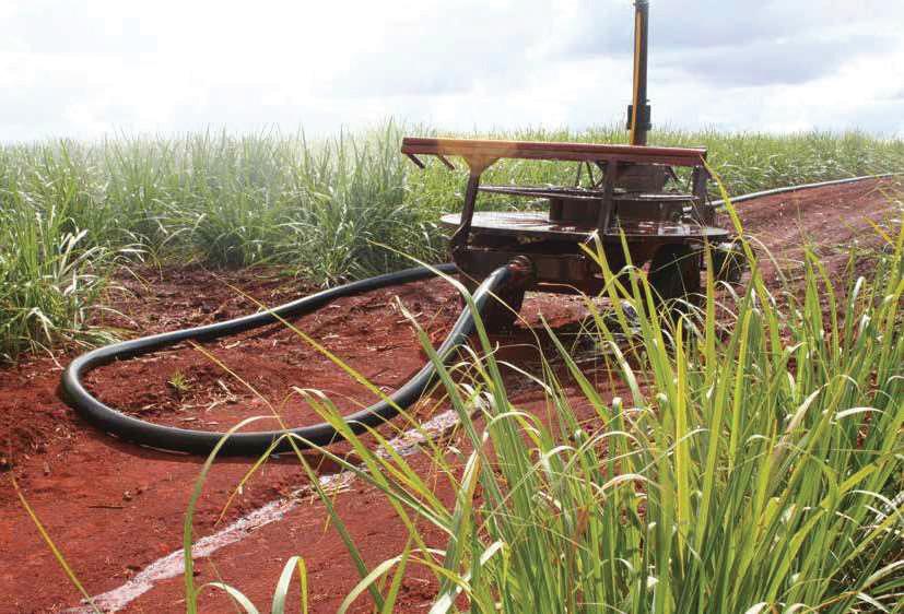
FLOWMASTER™ Irrigation Hose
FLOWMASTER™ Irrigation Hose
FLOWMASTER™ Irrigation Hose
FLOWMASTER™ Irrigation Hose
SANTOS SOLAR POWERED OIL WELL PUMPS PROJECT A SUCCESS

AGL has announced the completion of a landmark project to convert 20 Santos oil wells in South Australia and Queensland to be powered by solar energy rather than crude oil.
AGL Chief Customer Officer, Christine Corbett, said AGL’s Business Energy Solutions (BES) team had installed 1.2MW of solar panels and more than 2MWh of batteries over remote sites in the Cooper Basin.
“We’re proud to have worked with this leading Australian energy company by converting ‘beam pumps’ on oil wells to run on clean, renewable energy,” Ms Corbett said.
Santos Managing Director and Chief Executive Officer, Kevin Gallagher, said from an initial pilot well, the conversion project has been progressing above expectations.
“We created Australia’s first oil well running on solar and battery, off-grid,” Mr Gallagher said.
“There are more than 200 existing pumps across the Cooper Basin that could be covered and ultimately Santos aims to use solar power as the standard energy source for new onshore oil wells.
“Converting oil well pumps to solar power will deliver environmental and commercial benefits by reducing crude oil consumption, long distance fuel haulage and emissions.”
AGL’s Head of Delivery Operations, Brendan Weinert, said this world-first installation of a fully autonomous solar and battery-powered oil beam pump required AGL to adopt a different project delivery approach and overcome a number of challenges to deliver a technically and economically feasible solution.
“The solar and battery combination was sized to ensure continual operation 24 hours a day in some of Australia’s harshest climates,” Mr Weinert said.
“Each site has 160 solar panels with the capability to generate up to 100MWh of energy per year, which is enough to power 18 average Australian homes.
“They were installed using an innovative system which streamlines engineering and procurement, and provides cost efficiencies through deployment in-field.”
Major pumping station and water intake contracts awarded

CThe contract was awarded to Koppens Developments.
The current pumping station, located at the corner of Sheridan and Lily Streets, is the largest sewage pumping station operating in Cairns, taking wastewater from the Cairns CBD and Edge Hill residential catchments to the Northern Wastewater Treatment Plant.
The existing pump station is 65 years old and is at the end of its useful life.
The new pump station, expected to be completed November 2021, will be able to meet the capacity requirements for the catchment, accommodate future connections from upstream catchments, and address odour issues.
The council also awarded a $3.3 million contract to NQ Engineering & Fabrication to upgrade the water
intake at Crystal Cascades, which supplies the Freshwater Creek Water Treatment Plant.
The current screening arrangement at the intake is approaching the end of its useful life and requires replacement in order to maintain operational efficiency and continuity of raw water supply to the treatment plant.
In addition to the mechanical upgrades, the intake structure and walkways to the intake are proposed to be upgraded in order to minimise the effect of blockages during significant flood events and reduce the risk of damage to the screening equipment from rock falls.
The new water intake is expected to be completed March 2021.
NEWS pump industry | Autumn 2020 | Issue 31 www.pumpindustry.com.au 8
airns Regional Council in Queensland has awarded a $9 million contract to construct a new sewage pumping station in North Cairns.
Government cracks down on payment of suppliers

The Western Australian Government has announced it requires all Government Trading Enterprises (GTEs) within state minister portfolios to align with its policy that ensures suppliers of government goods and services are to be paid within 30 days.
This follows reports that some GTEs, including the Water Corporation, had different policies when it comes to paying suppliers and that, in some cases, contractors were being offered early payments in exchange for discounts on their invoices.
The State Government requires all commercial payments to be paid within 30 days of the receipt of the creditor’s claim, or within 30 days of provision of the goods or services (whichever is later), except where the terms or conditions of a contract relating to a claim for payment provide for alternative payment arrangements or where a discount is offered by a supplier for early payment.

ENGINEERS
WA Treasurer, Ben Wyatt, wrote to ministers, requesting them to ensure GTEs within their portfolios align with this policy. The Department of Treasury said it will be liaising directly with GTEs to confirm alignment with the 30 day policy.
“The State Government’s view is that all government agencies and Government Trading Enterprises must abide by the 30 day government policy for the payment of invoices,” Mr Wyatt said.
“Governments should lead by example and if suppliers do the work, they should expect to be paid in a timely manner.
“The issues raised...by Water Corporation suppliers were rightly deemed unacceptable by the Premier.
“As the Premier made clear...we don’t believe this is acceptable and have moved swiftly to ensure suppliers are paid within 30 days or sooner when possible.”
Enhanced Evaporation Systems For Effective Pond Management

Remote monitoring of weather and system operation
Intelligent adaptive control system to eliminate spray drift
No clogging in high TDS waters and suitable for any pH water
Enquiries: gjc@gjc.com.au 10 Peekarra Street, Regency Park, SA 5010 Phone: 08 8118 6450 www.gjc.com.au

Quiet Electric
NEWS 9 www.pumpindustry.com.au pump industry | Autumn 2020 | Issue 31
Contract awarded for village water reticulation system designs
The Upper Hunter Shire Council in NSW is another step closer to bringing town water to local villages after the tender to create designs for new water reticulation systems was awarded.
ADW Johnson was awarded the $250,855 (excluding GST) contract, with the new reticulation systems to bring town water to the villages of Blandford, Wingen, Parkville for the first time. There are also long-term plans to bring town water to Middlebrook and Gundy.
Once the initial designs are complete, which is expected to be in 2020, Council will consult with the communities of each village, including holding public meetings.
Community feedback and specifically how much demand there is for water services, will help guide which areas of the villages the reticulation networks will service. This will help determine the detailed designs, and the budgets and consumer costs.
Once the designs are completed, the Village Water Reticulation project will occur in two phases:
1. The Blandford, Wingen, and Parkville systems, which will be fed from the Scone to Murrurundi pipeline, will be constructed. These systems have received Restart NSW Government funding and are expected to be completed in 2022/23
2. Gundy and Middlebrook water systems are included in the design project, but no funding has been allocated yet for construction
The Scone to Murrurundi water pipeline project is on track to be completed before mid-2020.
Once the three pump stations are complete, testing will commence on the system of 40km pipeline and 450,000L storage tanks at Wingen and Warlands Range. The pump stations and water tanks are designed to move 2ML of water a day up and over the range between Scone and Murrurundi. Water storage in the tanks regulates the pumping.
Once the pipeline infrastructure is fully operational, the town of Murrurundi will have a water supply sourced from Glenbawn Dam, and will no longer be on level 6 water restrictions which have been in place since mid-2018.
Council will also be able to cease trucking water from Scone, which
has occurred for 12 months at a cost of around $500,000, of which around $200,000 will be subsidised by the NSW Government.
The pipeline project is estimated to cost $14.2 million, with over $13 million in funding provided by the NSW Government’s Restart NSW Water Security for Regions program. The remainder of the project funding is provided by the Upper Hunter Shire Council.
The council said it has received a $4,444,000 grant subsidy from the NSW Government’s Safe and Secure Water Program toward the water supply systems for Blandford, Parkville and Wingen and a new, larger reservoir for Murrurundi. The grant is dependent on the submission of a business case. This funding is in addition to the $1,736,000 already allocated to village reticulation and reservoirs from the original Restart NSW Grant.
Council is separately applying for funding for the Middlebrook and Gundy water supplies.
The pipeline and village connections are part of the NSW Government’s commitment to water infrastructure for regional communities, through the Water Security for Regions program and the new $1 billion Safe and Secure Water program.
PUMPED HYDRO PROJECT TERMINATED
AGL and Hillgrove Resources have confirmed they will not proceed with a proposed pumped hydro energy storage (PHES) project at the Kanmantoo copper mine in South Australia.
AGL’s Executive General Manager of Wholesale Markets, Richard Wrightson, said Hillgrove and AGL could not reach agreement on a way forward to progress the project.
“The signing was the start of a multiple stage process to progress the project and the agreements were subject to a number of conditions which needed to be satisfied within specified timeframes,” Mr Wrightson said.
“As a result, Hillgrove and AGL have mutually agreed to terminate the PHES Project Agreement without any ongoing obligation on either party.”
Mr Wrightson said AGL remains committed to continuing the development of energy storage projects such as pumped hydro and batteries to provide firming capacity to the market.
“We have announced a number of storage projects to provide the firming capacity the market needs, such as the 100MW Wandoan battery with Vena Energy in Queensland, a 30MW battery with ElectraNet in South Australia, and four 50MW batteries to be built by Maoneng Group in NSW,” Mr Wrightson said.
“We’re also looking at the feasibility of a pumped hydro plant at Bells Mountain in NSW, which if progressed will provide more than 250MW of new storage capacity, and we’re working with the NSW Government on a proposal to build a 50MW battery at Broken Hill.”
NEWS pump industry | Autumn 2020 | Issue 31 www.pumpindustry.com.au 10

Locked on Protection.
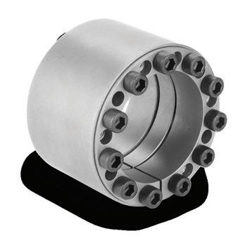
For more than 35 years, Rexnord Tollok® products have led the industry in Locking Assemblies. Our robust product offering features a wide range of options from simple and compact designs to advanced features such as corrosion resistant coatings, special bolting options, and high-speed applications to help companies maximise operable time. Our full range of locking assemblies can be tailored to fit our customers’ ever-changing application needs, and are ideal for use in heavy-duty and specially engineered environments. We offer a broad range of reliable, cost effective internal locking assemblies, shrink discs and rigid couplings to fit a diverse array of industrial applications that are dimensionally interchangeable with most of today’s industry standard units.
Additionally, Rexnord Tollok Locking Assemblies are a great alternative to a shaft/ hub connection such as key, splined, press fit, QD or taper-lock bushings. Customers benefit from reduced maintenance costs and plant downtime and are rewarded with increased productivity and plant efficiencies.
• Quick Installation time
• Equipment protection
• Increased life of system components
• Up to 3,389,550Nm capacity
Contact Rexnord today to see which coupling is right for your application. sales.australia@rexnord.com or Tel 02 4677 6000

© Rexnord Corporation. All Rights Reserved.
www.rexnord.com
Innovative approach to give more water to Tasmanian irrigators
An innovative two-stage approach to solving irrigation water reliability issues in Tasmania’s South East has been developed by Tasmanian Irrigation to enable farmers to expand, diversify and grow their agricultural businesses.
Tasmanian Irrigation Chief Executive Officer, Andrew Kneebone, said rapid development and investment through the Coal River Valley, Cambridge and Sorell areas in recent years, particularly in wine grapes, berries and green leaf crops, had resulted in increased demand for irrigation water across the South East Irrigation Schemes (SEIS) Stages One, Two and Three.
“The Tasmanian Irrigation team has been working incredibly hard to progress this two-stage approach, with the key focus on securing an alternate, reliable and cost-effective water source for the short and longer term for our irrigators,” Mr Kneebone said.
“The first stage is the development of a South East Interim Solution that will supply reliable raw water from the River Derwent to existing irrigators in the South East Irrigation Schemes.”
The South East Interim Solution will involve stages two and three of the South East Irrigation Schemes, bypassing the TasWater system as the primary water source, and instead extracting irrigation water from the River Derwent.
This will ensure a reliable water supply for current irrigators and farmers so they can continue to diversify, value add and expand their existing farming operations. It also makes available an additional 30ML of treated water per day for households in Southern Tasmania.
Access request letters have been posted to approximately 70 landowners that have been identified on a preferred pipeline corridor for the South East Interim Solution as part of the consultation process required to be undertaken to develop this project.
Mr Kneebone said the additional water supply will enable farmers to diversify and add value to their existing farming operations, while making available up to 30ML of treated water per day for households in Southern Tasmania.
“Interruptions to supply, coupled with the extreme dry conditions, resulted in restrictions being temporarily imposed on SEIS Stage Two and Stage Three irrigators in November last year, and we understand the impact this has on high-value crops and businesses,” he said.
“The South East Interim Solution and South East Integration Project will utilise existing DPIPWE water licences from the River Derwent for extraction of fit-for-purpose irrigation water, enabling 30ML of treated water a day to be freed up in the greater Hobart drinking water supply and irrigators to be given additional surety.”
The longer term South East Integration Project is one of the $496 million tranche three Pipeline to Prosperity initiatives that will see the augmentation of the current South East Irrigation Scheme’s Stages One, Two and Three, while meeting increased demand for irrigation water.
The Tranche Three irrigation projects (ten in total) are expected to deliver up to 2,600 full-time jobs and an additional $150 million in on-farm private investment, as almost 78,000ML of water is delivered via 479km of pipeline, seven dams, 23 pump stations and four power stations.
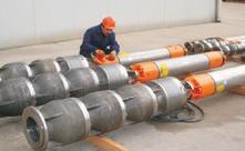
TURBINE PUMPS WELCOME TO THE BIG END OF TOWN.
Layne Bowler vertical turbine pumps have a proven record under the most demanding and toughest of conditions.
• Flows to 7,500 L/Sec
• Heads to 500 m
• Power to 1000+ kW

• Temperatures to 150°C
• Bowls Diameter up to 45 inch
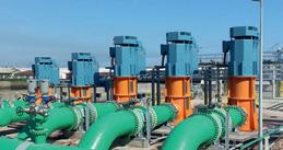
When high head and high flows are required look no further than this quality Italian made range.
• Flows to 5000m³/h
• Head to 220m
• Pumps that exceed EN733 (DIN 24255 standard)
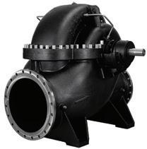
Brown Brothers Engineers have innovative solutions whatever your application. Contact us today about your requirements.


NEWS pump industry | Autumn 2020 | Issue 31 www.pumpindustry.com.au 12 VERTICAL
NCBK Series SKD Series NCA Series
DELIVERING PUMPING SOLUTIONS Ph: 1300 4 BBENG www.brownbros.com.au 02/20
Getting up close and personal with engines at PIA’s Breakfast Meeting in Melbourne

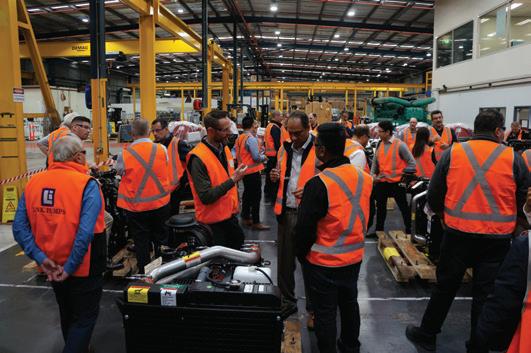
On 19 February, the PIA held its first Breakfast Meeting of 2020, with Cummins South Pacific hosting the event at its head office in Scoresby, Melbourne. Over 40 people attended, hearing presentations from Cummins and Macquarrie about engines, controls, panels and associated equipment for pumping systems.
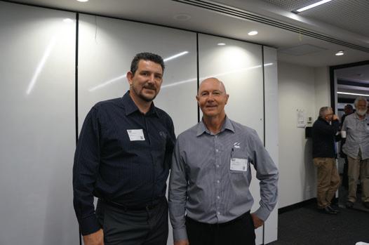
James Balnnin, PIA Vice President, opened the meeting and provided attendees with an overview of recent PIA activities, including an update on the revision of the Pump Technical Handbook and the Pipe Friction Handbook, as well as plans for future Breakfast Meetings and training courses for 2020. He also thanked Bryce Colville, Regional Sales Manager –Industrial at Cummins South Pacific, for hosting and organising the event.
Following the opening presentation, attendees heard from Sam Jones, Sales Executive Victoria, and Simon Rigopoulos, Applications Engineer at Cummins South Pacific. Sam provided an introduction to Cummins South Pacific, talking about what the company does and the range it has to offer, including its CustomPak and ComPak ranges. Simon spoke more on the technical side of the products, explaining some of the various features and what engineering expertise Cummins can provide
14 pump industry | Autumn 2020 | Issue 31 www.pumpindustry.com.au PIA NEWS
Attendees were treated to a facility tour, where they got to see and ask questions about the products.
More than 40 people attended the PIA Breakfast Meeting at Cummins South Pacific, Melbourne.
PIA Vice President, James Blannin, and Bryce Colville, Regional Sales Manager – Industrial at Cummins South Pacific, organised the event.
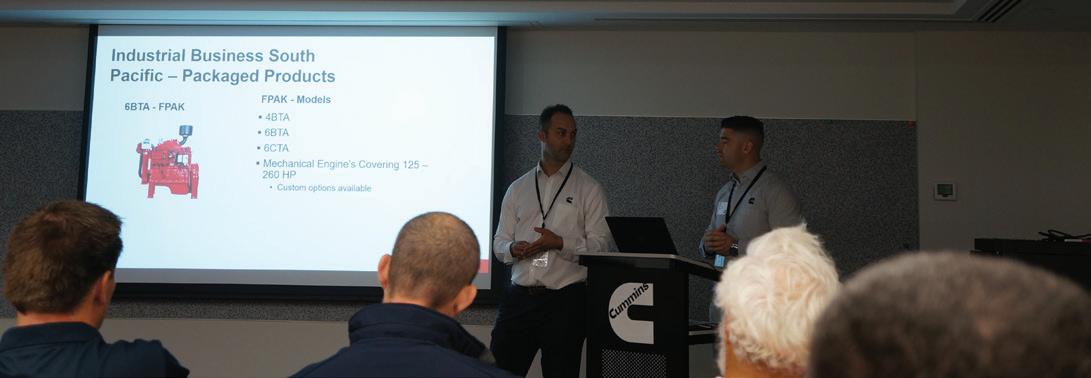
customers to ensure they’re getting the right engine for their requirements. The key takeaway for attendees being that the equipment Cummins provides extends beyond what is in the brochure, and that they will find a solution if a client requires something different.
Attendees were engaged with the presentations, asking questions throughout the presentation about the products.
Jackson Hayes, Head of Engineering & Sales at Maquarrie Corporation, also did a short presentation about Macquarrie, and what it does and can offer, as well as its relationship with Cummins and the pump industry in general.
Following the presentations, attendees were given a tour of part of the Cummins South Pacific facility. The highlight of the tour was getting to see the various ComPak models available and having a chance to ask further questions about the range. Attendees also took this chance to further mingle with others to discuss all things pump related.
The tour and Breakfast Meeting finished with attendees seeing other products from Cummins, including those for truck and fire applications, as well as its massive QSK95 diesel generator, nicknamed the ‘Hedgehog’.
To find out about upcoming PIA Breakfast Meetings, keep an eye out on pumps.asn.com, PIA social media channels, as well as the Pump Industry newsletter and online events page for updates and details.


15 www.pumpindustry.com.au pump industry | Autumn 2020 | Issue 31 PIA NEWS
59 Export Dr Brooklyn VIC 3012 Email: sales@wellcross.com.au wellcross.com.au 656 276 AUSTRALIA’S TRUSTED DIESEL POWER AUSTRALIA’S TRUSTED DIESEL POWER Adelaide | Brisbane | Melbourne | Perth | Sydney | Townsville POWERED BY POWERED BY CROSSLEYTM ARE YOU RUNNING YOUR PUMPS WITH GENERATORS? We can custom design generators to suit your pumping and irrigation needs, soft start, VFD or DOL.
Simon Rigopoulos, Applications Engineer, and Sam Jones, Sales Executive Victoria at Cummins South Pacific presented at the PIA Breakfast Meeting.
NEW RANGE OF EN733 PUMPS: WORLD-LEADING PERFORMANCE
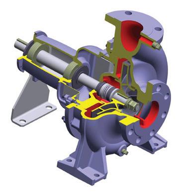
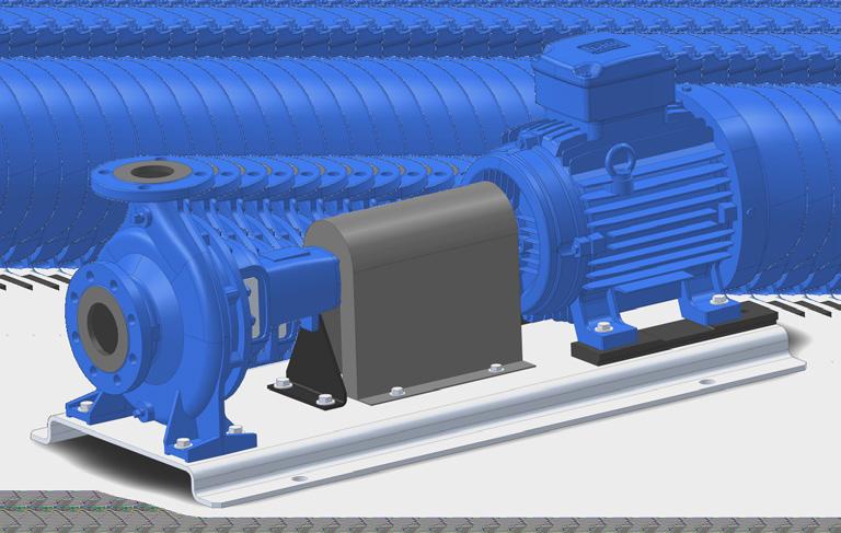
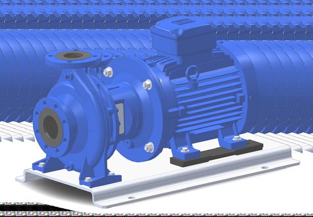
Ebara Corporation (Japan) has recently released its new global range of EN733 standard end suction centrifugal pumps.
Utilising the most advanced hydraulic computer design software available, Ebara engineers in Japan have been able to improve and increase the pump efficiencies of the new GS range above most other available pumps of similar design and standard on the global market.
As a major manufacturer of industrial pumps to JIS and API610 standards, Ebara Corporation has embarked on a globalisation of its range of pumps for the world market. This includes the introduction of a range of industrial pumps to European EN733 standards and a new range of vertical multistage pumps.
The new Ebara GS range of EN733 standard pumps are manufactured in component form at Ebara Corporation Japan owned and managed factories in the Asia Pacific region with final assembly of market range models undertaken by skilled tradesmen at Ebara Pumps Australia’s Melbourne facility.
The new GS series are 16 bar rated pumps, with a close coupled version (GSD) offered as well. The GSD is now available in Australia.
About Ebara Corporation
Ebara Corporation was founded in Japan in 1912 as a manufacturer of pumps. Today, as a group, it consists of more than 70 companies in six continents with a workforce of more
11,000 people and with company owned and Japanese managed factories in eight countries covering four continents.
The huge scale of production and distribution is matched by a constant commitment to research, development and design of new products and the modern technologies for manufacturing them. Ebara products have gained a worldwide reputation for their technology and quality.
Contact your local Ebara dealer or Ebara Pumps Australia for more information.
Two of the more popular models that are stocked in Australia are both solids handling pumps. For more details contact us at Ebara Pumps Australia or visit our website.
Stamped stainless steel pumps with open impeller
Maximum 19mm passage size
50mm discharge
1.1 to 1.5kW - 1 phase
1.1 to 3.0kW - 3 phase


Cast iron submersible pumps with semi vortex impeller
32 to 56mm passage size
(Depending on model)
50 and 80mm discharge
0.4 to 0.75kW - 1 phase
0.75 to 3.7kW - 3 phase
Manual or automatic


16 pump industry | Autumn 2020 | Issue 31 www.pumpindustry.com.au PIA MEMBER NEWS | PARTNER SOLUTIONS
MODEL DWO
MODEL DVS
New hydraulic design - World leading performance
End suction single stage centrifugal pumps
Pumps to EN733 dimensions
16 Bar rated. PN16 flanges (24 Bar hydrostatic test pressure)
High efficiencies. MEI ³0.6 (Minimum Efficiency Index)
Mechanical seals to EN12756
Protectors to ISO13852
O’ Ring seal for casing
Cast iron components ED painted (Electro deposition painting)
Combining over 100 years of experience with the latest computer aided design, EBARA has developed the new GS series of pumps that offer world leading performance and efficiencies. Looking
Available soon
www ebara com au EBARA PUMPS AUSTRALIA PTY. LTD 7 Holloway Drive Bayswater, VIC. 3153 P h : 0 3 9 7 6 1 3 0 3 3 sales@ebara com au
going
expectations
ahead,
beyond
Model
2900 rpm 1450 rpm GSD range GS range GS range - 41 pump sizes from 32-125 to 200-500 GSD motor pump versions available from 1.1 kW up to 75 kW (4 pole) and 110 kW (2 pole)
in Japan
Assembled
Australia
Designed
-
in
Available now!
Sewer bypass system uses layflat hose
There are numerous cast iron sewer pipes still in service around Melbourne, which have served the city and the suburbs well. However, with age, these pipelines have corroded and have needed to be replaced and upgraded. The Hawthorn sewer main, in a bustling suburb just 7km from the CBD, was one such pipeline that needed relining. The challenge for Melbourne Water was how to set up a 350mm diameter bypass sewer line, without interrupting traffic flow across busy Power Street.
Fortunately, there was an open stormwater drain running under the road and the engineers discussed the possibility of using this drain in which to locate a bypass pipeline. This drain, however, was also built many years ago with bricks and cement, and would not be able to sustain the weight of heavy equipment without suffering major structural damage.
The drain was also very sinuous, so rigid poly pipe was not a viable option as a bypass solution. Another complication was that there were also only two areas along the 800m section of drain that could be used as access points.
Peter Sherwood, the Victorian manager for National Pump and Energy (NPE), was consulted as he had undertaken many sewer bypass projects for water authorities, including four systems using layflat hose.
His experience and recent success using 12 inch layflat hose for the Melbourne Water uncontrolled spills project at the Croydon main sewer was referred to. In the Dandenong Creek near Croydon, Mr Sherwood had proven the benefits of using the Crusader Hose layflat hose for a similar application.
Mr Sherwood arranged for the engineers to visit Crusader Hose, a pioneering Australian manufacturer of layflat hose. Melbourne Water engineers had identified a high risk of using flexible hose for the sewage bypass in the case of failure in the Hawthorn project.
“It would be catastrophic to have all that sewage in an open drain in case of a hose burst,” they told Francois
Steverlynck, the Managing Director of Crusader Hose.
A visit to the factory was arranged for their subcontractors, during which all the strengths and safety margins using quality Australian-made hose were shown.
“This included showing them the secure couplings and abrasion resistance test results,” Mr Steverlynck said.
Crusader Hose not only pioneered the development of layflat hose in Australia, but also manufactures reel systems to deploy and recover the hose. A lightweight and easy to use reeling system was demonstrated so that the layflat pipeline could be easily installed without any risk of damage to the open stormwater drain.
“We proved to them the success of layflat and were very happy to get approval,” Mr Steverlynck said.
Whilst NPE set up its pumps, the pipeline was deployed and all couplings were connected in two days with minimum fuss. Mr Sherwood carried out his pre-operational checks and raw sewage was pumped through his BA300 wastewater diesel pumps at flow rates between 100 to 300L per second for five days whilst the main sewer relining took place.
“There was no traffic flow loss across Power Street during this time,” Mr Sherwood said.
“All in all, the layflat hose once again proved itself as a successful alternative for sewage pumping when poly pipe cannot be used.”

18 pump industry | Autumn 2020 | Issue 31 www.pumpindustry.com.au
PIA MEMBER NEWS | PARTNER SOLUTIONS
Hawthorn drain has many curves and turns
AQUALINE LAYFLAT HOSE
TEMPORARY WATER
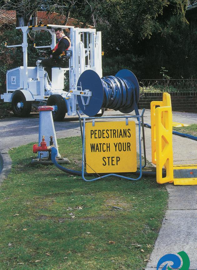
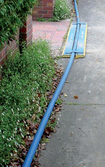
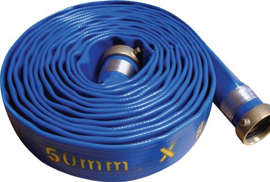


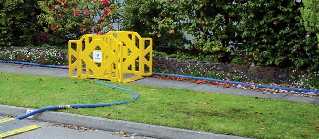


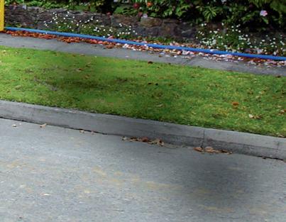
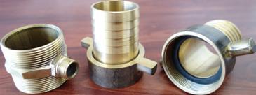

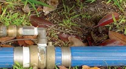


Aqualine is rolled out as a temporary water supply system while the Utility carries out pipeline refurbishment works. The hose is usually cut into 9m lengths and a T piece coupling is attached at each end. From these outlets, customers can be connected to the main line, while pipe renewal or refurbishment takes place. It is ideal for:
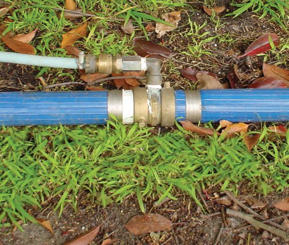
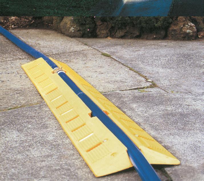
•Civil works
•Mining projects
•Potable bypass by utilities while refurbishing damaged water pipes
Main Features


Portable water approved to AS4020
500m can be easily rolled up onto a drum
Easy and compact for transport
Secure couplings stay on under high pressure
Can be made in any length
Large range of diameters available
Reeling system also available


FOR
Customised Layflat Hose Systems Crusader Hose Pty Ltd 22 Industry Place, Bayswater VIC 3153 Australia Telephone: (03) 9720 1100 www.crusaderhose.com.au For any enquiries, email sales@crusaderhose.com.au
BYPASS
Better, easier and cheaper using 4G
ETM, one of Sweden’s leading manufacturers of Industrial IoT cellular edge solutions, has released two products that exploit these new technologies, with the new family of cellular remote monitoring, alarming and logging solutions for analog and digital signals:
• DeltaBlack optimised for industrial environments. DIN rail mount, wide DC operating voltage and flexible I/O configuration
• DeltaBlue designed for outdoor remote deployment. Battery-powered, IP66 enclosure, GPS, vibration/ movement detection and flexible I/O configuration



Improvements in 3G and 4G mobile network coverage, advancements in battery technology, low power electronics and cloud services have enabled the development of a new generation of devices that can be used to remotely monitor, control and log data from pumps and associated infrastructure. For more information about DeltaBlack and DeltaBlue call (02) 9956 7377 www.etmiot.com.au.
ETM ensured that simplicity and cost effectiveness were two key criteria in designing its new range. Recognising that deploying cellular or mobile network devices have often been a frustrating exercise for engineers having to deal with procurement, IT departments and having to select antenna, power supplies etc., these units come bundled with active Telstra SIM cards and are preconfigured for specific inputs such as temperature, current and vibration.
Mining Pumps

DeltaBlack and DeltaBlue connect to ETM’s IoT Cloud Dashboard (EWO) for real-time and historical data display. In addition, pre-set customised alarms can be simultaneously sent to multiple recipients as simple user-friendly SMS text messages direct from the device.





20 INDUSTRY NEWS | PARTNER SOLUTIONS
INFRASTRUCTURE:
MONITORING REMOTE PUMP
DeltaBlue
DeltaBlack
Maximizing the savings in the life cycle of mining equipment An hour of plant shutdown can cost a mine more than $ 90,000 AUD. This fact is what inspired ITT Goulds Pumps to use the latest advances in hydraulic engineering to design and build pumps to operate in the toughest conditions. This large portfolio of ITT Goulds Pumps hard metal and rubber-coated slurry pumps are available from ITT Blakers, a fully integrated pump service provider, with a full portfolio of premier industrial products complementing the ITT Goulds Pumps pump range. Model VRS Model 3196 Model SRL Model XHD T: 1300 333 488 | E: sales.blakers@itt.com W: www.ittblakers.com
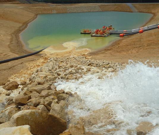
WORLD’S HARSHEST CONDITIONS CREATE ENERGY EFFICIENT PUMPS
With over 50 years’ experience, AllightSykes is a market leader in the design, manufacturing and distribution of lighting, dewatering and power solutions. The company prides itself on providing robust, reliable products that make ownership and operation safe, simple and cost effective for customers.
The company has built itself into a major force in water management across the globe. The company now has branches stretching from Australia, New Zealand, Asia, the Middle East and Africa, to South and North America.
Company CEO, Gus Elliot, said the business owes this success to the harsh environmental conditions experienced in Australia.
“AllightSykes was founded in Australia, so when we started designing pumps, we built them to withstand the harshest conditions this country could offer. Fortunately for us, those conditions are on par with the harshest conditions anywhere in the world. What we built here worked anywhere,” Mr Elliot said.
Designing, manufacturing and servicing its own equipment has given AllightSykes invaluable knowledge of how its pumps operate in the most diverse environments. Feedback from the field helps the team refine its products that have become recognised as some of the most energy efficient and reliable in the world.
Latif Ahmad, General Manager of Technical Services, said that the energy efficiency comes from the leading-edge design elements of the pumps.
“Sykes pumps have the lowest shaft stiffness ratio in the business, are built with superior corrosion resistant materials, and feature the ability to reset the impeller and wear plates. This reduces the need to prematurely replace wear parts, and reduces the overall energy consumption during the pump’s operating life,” Mr Ahmad said.
For businesses, this means less energy used, less pump downtime, less unplanned repairs and maintenance, less parts used, and longer pump life internals.
Mr Ahmad said that providing the right equipment is just the first part of the equation.
“AllightSykes stands out because we’re more than a manufacturer. We know how important it is for many of our customers to be up and running 24-hours a day, so we provide the support to help operate this way,” Mr Ahmad said.


INDUSTRY NEWS | PARTNER SOLUTIONS 22

Premium Couplings from Global Leaders
CMD Winex
Winex DG Grid Couplings
Bore capacity 360mm
Torque range 52Nm > 186,000Nm
Chrome vanadium, heat treated & shot peened grids
Replaceable tooth rings from size DG15(1150T10)
Winex T & S Series Grid Couplings
Bore capacity up to 390mm
High torque range 90Nm > 800,000Nm
Chrome vanadium, heat treated & shot peened grids
Replaceable Tooth Rings T series from size 28 and the complete range in S Series
+61 (0) 3 9796 4800 Melbourne Perth info@drivesystems com au 8/32 Melverton Dve, Hallam, VIC 3803 drivesystems.com.au TECHNICAL EXCELLENCE & INDUSTRY EXPERIENCE
Rexnord
+61 (0) 455 320 552 2/64 Baile Rd, Canning Vale, WA 6155
KEEPING THE WATER FLOWING IN AUSTRALIA’S LARGEST MAN-MADE CONSERVATION AND RECREATION LAKE

Lake Gkula, located at Woodford Folk Festival in Queensland’s Moreton Bay Hinterland, is Australia’s largest conservation and recreation lake, and relies on a series of pumps to keep the water constantly flowing through its wetland filtration system, and to ensure the safety of its biodiversity and for swimmers. We sat down with the lake’s designer
Patrick Handley, CEO at Waterscapes Australia, to find out more about how the system works, the equipment and the construction process.
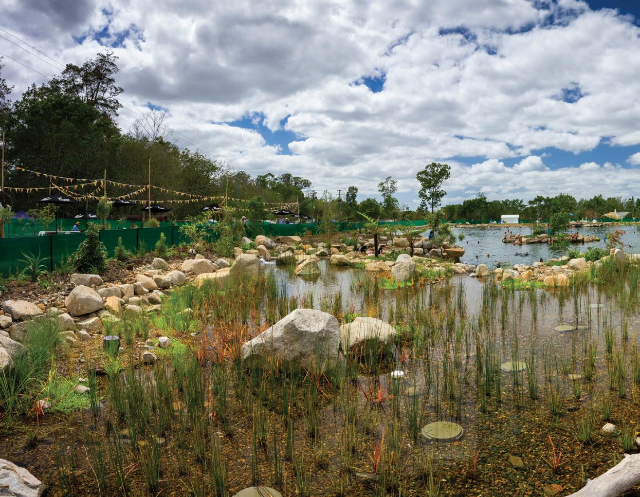
Officially opened last December, the lake cost around $2.6 million to build with all the water sourced onsite from dams. It features waterfalls, a 90m-long beach along one bank as well as a second smaller beach, an island and plenty of large rocks. It is a chemical free lake, using all-natural systems to guarantee safe water quality with an abundant fish and plant life, including 18 species of native, freshwater fish and 9,000 endemic aquatic plants in and around the facility so far.
At over 12 million litres capacity and taking up an acre and a quarter, Lake Gkula was designed and built as an aquatic ecosystem where people can swim, snorkel, learn about and appreciate local fish and plant species.
The lake honours the region’s traditional owners, the Jinibara people, naming it after one of their principal spokespersons, Uncle Noel Blair, a much-loved and influential figure in the Woodfordian community Noel’s Indigenous name is Gkula which, translated, means Koala.
Getting the design brief
Waterscapes Australia was contracted to design and construct Lake Gkula, including the pumping and filtration systems.
Mr Handley said the design stage took about a year, with discussions starting in 2018 about what Woodfordia wanted to achieve. Woodford Folk Festival’s founder and director, Bill Hauritz, was very clear and incredibly visionary in the instigation of this project and what was to be achieved.
"The design brief was that it needed to be large enough to allow 400-500 people to swim at one time, while also being
a natural ecosystem, to fit into Woodfordia’s philosophy that supports the local ecology and the culture of the festival. It also needed to be able to be used all year round to offer more options for functions and income during the year,” Mr Handley said.
“This is the biggest system I’ve designed and constructed, and it’s actually the largest Aquascape naturally filtered, purpose-built swimming lake in the world.”

Keeping the water flowing
Key to the design of the lake was a circulation system to keep the water moving and flowing through the lake and filtration systems. High circulation, such as is found in healthy rivers and streams, is key to designing and maintaining a healthy body of water with the intended use and patronage in mind.
"The system needed to be able to move water out of the beach areas quickly and to the pump intake or skimmer bay
24 pump industry | Autumn 2020 | Issue 31 www.pumpindustry.com.au
WATER

area. That was achieved through well-designed circulation jetting placement along those beaches and lake edges,” Mr Handley said.
 Patrick Handley, CEO, Waterscapes Australia
The system is designed so that pumps draw water into a specifically placed intake bay where floating debris is collected and removed, thereby reducing the accumulation of organic material and nutrient loads in the lake system. Pumping 1,000,000 litres of water per hour, the lake turns over its volume every 12 hours.
There are four external pumps maintaining the necessary circulation. Two 300,000L/hr pumps supply two Aquascape upflow wetland filters before spilling back into the lake over several waterfalls. The beach and edge circulation system is powered by two 200,000L/hr pumps with 16 jets positioned around the lake to increase movement and circulation back to the skimmer bay.
"The wetland filters are designed as massive surface areas that support massive beneficial bacteria and micro and macro organisms. We have calculations for those as to how much water we need to be able to move through them per minute per square meter. That is in relation to the body or surface area of the whole system as well,” Mr Handley said.
“For smaller systems such as recreation ponds we use bigger filters in relation to the water body to be filtered, generally between 20-35 per cent of the surface area. On larger bodies of water we are able to design smaller filters as the entire lake floor is covered in pebble which provides massive additional habitat for beneficial bacteria. In this case, the filters are 12 per cent of the lake's surface area.
“The wetland filters are upflow filters – they’re high flow aerobic filters with massive surface area for beneficial bacteria, and micro and macro organisms that filter the water and compete with pathogens.”
Selecting a filtration system
Mr Handley said the filtration system design and the equipment used in the project is fairly new to Australia,
although developed and used successfully for many years now in the United States and commercial projects around the world.
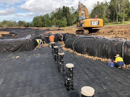
“We use the Aquascape Inc Upflow Wetland Filter supplied by Aquascape Supplies Australia. This system uses a snorkel and centipede system with a matrix which creates a void under the filter substrate where the water slows down, eddies, drops its silt load and then moves up through the different layers of substrate or river pebble. There are three specifically graded layers of river pebble,” Mr Handley said.
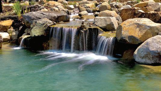
“The design minimises the chance of ‘chimneying’ of the water through the pebble and maintains the filters aerobic condition. We want that water to move laminar around those materials to maintain maximum contact with the biofilms and beneficial bacteria and organisms that form it. That’s where the filtration happens. The snorkel allows access to the floor of the filter to carry out future maintenance such as backflushing.”
The filtration system also uses a microbubble system that produces a bubble which is about 40 microns.
“It uses atmospheric, compressed air and a micro diffuser to infuse the body of water with a very small air bubble that doesn’t float,” Mr Handley said.
“A 40 micron bubble does not have enough surface area to be fully buoyant and stays suspended in the actual water column. This saturates right down to the deepest point. So it’ll
25 www.pumpindustry.com.au pump industry | Autumn 2020 | Issue 31 WATER
go under the pebble, down into any detritus at the bottom and create aerobic conditions where it speeds up decomposition. This system will actually reduce accumulated organic load build up in lakes and retention ponds.
“We have installed probes in the filters and key areas of the lake and over the festival period of late January we were recording between 27.5° and 29.3°C water temperature, and we had between 93 and 100 per cent oxygen saturation.
“This is an incredible result. It meant that the system had plenty of oxygen availability to support very large populations of aerobic bacteria. So there’s really good processing of waste material going on there.”
Procuring the pumps
The pumping system comprises two wetland filter pumps that run 24/7 and two relatively smaller pumps to circulate the warmer water out of the shallower areas to reduce ‘hot spots’ that would promote algae growth, and to move water from the swimming zones. The small pumps are on timers but run 24/7 when there are higher swimmer loads such as during festivals when lots of people are using the lake.
The pumps and plumbing all used 200-225mm PVC pipe which then split off to a three inch or 80mm flexible PVC pipe into the jetting areas and the bottom of the wetlands.
“The pumps were supplied by Grundfos through Reece Irrigation. We specified the flows we needed. Because these filters are aerobic – and we aim to create mesotrophic or oligotrophic conditions, which is low nutrient, high oxygen – we want a good flow through these filters to provide oxygen to the wetland,” Mr Handley said.
WATER
26 pump industry | Autumn 2020 | Issue 31 www.pumpindustry.com.au

As well as meeting the required flow rates, the pumps also needed to be energy efficient and run at the lowest kilowatt possible as the they need to run 24/7 and low power consumption and energy costs for Woodfordia was important.
The two larger pumps are 7.5kW each and the small pumps are both 5kW units, with the system running about 25kW per hour when in 24/7 festival operation. The kilowatt usage will reduce during winter and low use times when the circulation pumps are running on a pumping schedule during daylight hours only.
The system is currently partially supplied by solar system, with Woodfordia working towards the whole lake’s electrical consumption to be 100 per cent renewable in the future. Maintaining the system and the lake
Mr Handley said the system is relatively simple to maintain and doesn't take a lot of input as no chemicals are used.
“In high load times, we may add additional beneficial bacteria cultures to maximise the biologic process and make sure there’s good populations of beneficial bacteria throughout, especially in those wetland filters.
“Six months from construction we will conduct a backflush of the wetland filters to remove accumulated sediment introduced during the construction. The wetland filters are designed so that the sediment settles in chambers under
the filtration material. This slurry is pumped out during the backflush procedure.
“We then recommend a backflush every two to three years, depending on sediment loads and organic material loads.
“Over time, as the majority of the sediment is processed and removed, the backflush intervals are increased. These systems thrive and become better the more they are used, the more they are stirred up by swimming and other activities.
“Ongoing maintenance includes pruning back aquatic plants, making sure the fish populations are healthy and recommended maintenance service on the pumps. The microbubble unit has a 500 hour service as well.”
Constructing the lake
Constructing such a large lake was a big task that came with challenges that needed to be considered and overcome.
Mr Handley said bulk moving works took three weeks using a 40 tonne excavator, D9 dozer and body trucks to move the excavated material. All the excavated material was utilised on the Woodford Festival site so the bulking out logistics were fairly simple. Shaping the lake, installation of the geotextile and Firestone EPDM liner, and rock placement including waterfall construction then took a further four and a half months to complete.
WATER
27 www.pumpindustry.com.au pump industry | Autumn 2020 | Issue 31

“We had two to three crews at a time working on the project, each comprising of trained Aquascape contractors who came from all over Australia to work on the build. These guys are all very talented water feature designers and builders and put their hearts into the aesthetics within my design. The fantastic outcome could not have been achieved without their construction experience and input. Machinery-wise we utilised a 30 tonne and a 14 tonne excavator. We had a nine tonne site loader, a couple of big Posi-Track Loaders, and some small excavators as well for channel trenching,” Mr Handley said.
“Lake Gkula is over five and a half metres at the deepest point, and it’s carved out in terraces. We placed rocks on every terrace wall to create habitat and cover the lining membrane. There’s a whole technique to shaping these systems prior to lining, so we can build structurally and aesthetically.
“The liner was also a challenge. The liner used is a Firestone EPDM rubber and transporting and maneuvering the panels limits the panel size used. With 9,600m2 of liner required, the team we had to bring in and roll them into place – each 15mx60m panel weighed a tonne – and we cold-seamed them in-situ. EPDM does not require a heat seam or join. We learned a lot of valuable techniques on how to do this on a large-scale project, you’re not dealing with straight seaming lines, there are lots of curves and liner bunching that has to be worked with. The team had to come up with some pretty creative processes to be able to seam onsite with the help of a Firestone trained technician from Aquascape Supplies Australia.”
Logistics was another challenge to get the amount of construction rock and materials required.
Mr Handley said 2,000 tonnes of granite boulder and 1,800 tonnes of river pebble was sourced from local suppliers. Specific ratios of boulder size are used in these types of designs, rock ranging in diameter from 200mm to 1.5m was supplied by Gympie Granite. The pebble for the filters was triple washed to reduce sediment. Additionally 1,600 tonnes of triple-washed river sand was locally supplied.
“As for all of our projects, we use materials from local suppliers and had no issues getting the supply of material so the project could move along.
“A 50 tonne crane was contracted to place the majority of the boulder into place. We had to consider how we would place the rock onto the membrane of the lake which is almost 100m long, by about 70m wide. In our process, and from many years of experience, we have developed a rigging method that allows
us to place each rock exactly how we want it. This is how we achieve the aesthetics in our designs.”
Mr Handley said Woodfordia wanted it to be natural and pleasing to the eye, as if you were going to the local creek, so aesthetics was key when it came to constructing the lake.
“Aesthetics and functionality is a fine line but essential in creating a living aquatic ecology that we are drawn to interact with.”
Putting the system to the test
The 2019 Woodford Folk Festival took place not long after the lake’s opening and put the lake and its pumping and filtration systems to the test with about 20,000 people using the lake over the course of six days.
Mr Handley said despite being put into use so soon after commissioning, the water quality and chemical results were fantastic, with the lake behaving as designed.
“The lake was operational for only 2.5 months prior to the festival and the ecology was still very young, the wetland filters and overall system can take 12 months to fully mature,” Mr Handley said.
“We tested the water quality four times a day for dissolved oxygen levels, and microbiological and water chemistry as well for the obvious things. Plating for fecal colonies was conducted onsite so we had almost immediate feedback on the lake's water quality. At one point during the festival, 550 swimmers were recorded in the water at one time and we wanted to know the conditions were good. There were no cyanobacteria or other pathogens sometimes associated with recreational waters. It stayed well within the parameters for safe recreational waters, as per Australian standards.”
An developing ecology to be experienced in the future
Mr Handley said the system as a whole, the ecology, is still maturing and the team will continue to introduce endemic fish and plant species to create a strong resilient aquatic ecosystem.
“Strong breeding populations such as Agassiz’s perchlet, South East Queensland Rainbow and Blue-eyes are already well established. Eelgrass beds and native water lilies are also establishing strongly in the lake’s habitat zones. In time, Mary River Cod, Lung Fish and Bass will be introduced as the apex species. How epic will that be, being able to snorkel and view such fish in a natural habitat?”
pump industry | Autumn 2020 | Issue 31 www.pumpindustry.com.au
28 WATER

The ASM C Series sump pump is built tough for reliable uninterrupted operation in the most demanding conditions. What makes the ‘C’ Series so robust is what it doesn’t have; a submerged motor, bearings or mechanical seals, the primary causes of failure in conventional sump pumps. The heavy duty shaft and bearing assembly is above the mounting plate, clear of the sump environment. This feature allows the pump to run dry indefinitely without damage, pump extreme temperature liquids and have a high tolerance to abrasive fluids.
Additional to these benefits is the fact that the pump is always
primed and ready to work. The C Series is available with material and design options for clean liquids, solids handling, chemicals and extreme temperatures.
This is the pump you need when you want peace of mind. For more information contact ASM Pumps on (03) 9793 7577 or visit asmpumps.com.au
TOP THREE BENEFITS OF VFDS FOR IRRIGATION PUMPING
Variable frequency drives (VFDs) are now widely used for irrigation pumping applications due to the many cost saving opportunities they provide. Here, we look at the top three benefits irrigators can take advantage of by installing VFDs on irrigation pumps.
Energy savings through system flexibility
One of the major benefits of VFDs is that they can be programmed to run the pump at a certain speed and flow rate. This is beneficial for agricultural irrigation systems that are zoned by field type, crop type, crop maturity and elevation, and can require different flow rates.
In the past, irrigators needed to size the pump for the worst possible case, and then use a combination of valves to try to run the system at the best efficiency point (BEP). However, it is difficult to meet the BEP in all zones this way, so there are inevitably always zones where the pump is oversized, resulting in increased wear on the system, higher energy consumption and higher costs.
VFDs allow irrigators to customise the way the system runs so that pump speed will slow down, and flow and pressure reduced to operate a smaller zone at the BEP. This has long-term benefits as there will be less system maintenance required, equipment will have a longer lifecycle, and energy costs will be greatly reduced.
Reduced water loss
By ensuring pumps operate at the optimum pressure for the irrigation application, VFDs have cost and environmental saving benefits for water. If an irrigation system is operated with more pressure than required, sprinklers will mist which creates smaller water
droplets through the nozzle that are more easily moved by the wind and evaporated into the atmosphere. This results in a loss of water as it is less likely to reach the crop.
VFDs also allow irrigators to adjust pumps to automatically suit conditions so that water is not unnecessarily delivered. By doing this, scheduling is improved, rootzone waterlogging is avoided and there is no water wastage. These have the added benefits of increasing the chances for higher crop production and reducing energy costs.
Maintenance savings
As well as lessening wear to equipment due to operating outside of BEP and higher pressures than necessary, VFDs also have other features that help to further reduce maintenance costs and increase the lifecycle of pumps.
VFDs are soft-start devices so problems associated with waterhammer and excess power draw during start-up are eliminated, and flow or pressure surges are reduced. This decreases wear, particularly on bearings and seals.
The Franklin Electric advantage
Franklin Electric’s line of VFDs – DrivE-Tech – was designed and developed to optimise, control and protect pumping systems, and is compatible with different types of pumps, including vertical multistage, centrifugal and submersible. It can be
used for water supply and irrigation applications, and is suitable to operate most new or existing systems up to 15kW.
The DrivE-Tech enclosure is manufactured from die-cast aluminium, and is sturdy, lightweight, easy to cool and compact in size. The panel has a IP55 rating, so it can be installed in humid and dusty places.
It has a display placed on top of the device and a buzzer in case of an alarm to help to operate the VFD efficiently and easily.
DrivE-Tech Solar is also available for efficient pumping and movement of water using the sun’s energy to generate DC power from solar arrays which is then converted to AC power to operate the electric motor of a new or existing above or below ground water pump. It has an enclosure rating of IP65, with an aluminum body and 304SS metal parts.
The DrivE-Tech Solar constantly adapts pump speed to the available solar irradiation to maximise the amount of pumped water and allow continued operation even in low irradiation conditions.
It also offers operation of 3 phase 230V or 400V motors to power pumps with motor needs up to 15kW–30 amps maximum.
The knowledgeable team at Franklin Electric can help you find the right VFD for your installation to make sure you’re getting the most benefit from it.


30 pump industry | Autumn 2020 | Issue 31 www.pumpindustry.com.au
WATER | PARTNER SOLUTIONS
Reliable irrigation solutions

Franklin Electric has over 75 years of experience providing industry-leading technical service to the irrigation industry, providing support and advice to keep you pumping in even the most rural areas.
Leading the industry in service standards

www.franklin-electric.com.au 1300 670 060
Floating pumps help boost water supply to Guyra
By Eliza Booth, Assistant Editor, Pump Industry magazine
As Australia continues to battle one of the worst droughts in living memory, more regions are looking to secure their water supplies now and into the future. One NSW council has taken this challenge on headfirst, constructing a purpose-built pipeline and accompanying floating pontoon pump infrastructure to increase water quality and flexibility for locals.
Guyra, in the Northern Tablelands of NSW, has been hit hard by the drought. Supplies in Guyra Dam were on track to run out in mid 2019 and proactive measures from the region’s Council and State Government were needed to keep households and businesses supplied with town water.
Fortunately, Armidale Regional Council had already embarked on the construction of a $12.85 million pipeline linking Guyra’s town water system to the much larger Malpas Dam.
The Malpas Dam to Guyra pipeline had been initiated in 2017 after previous extended dry periods raised issues of poor water quality when levels in Guyra Dam became low. The pipeline gave the Guyra township access to Malpas Dam’s 12,000ML capacity, instead of relying solely on the 450ML Guyra Dam.
The State Government stepped up with a $12.375 million grant and the pipeline was given the green light in 2018. Just months later, the emerging severity of the drought gave the pipeline added urgency and value. The project was fast-tracked and was officially opened in October 2019.
32 pump industry | Autumn 2020 | Issue 31 www.pumpindustry.com.au
WATER
Urgent need for a secure solution
The development of a solution to Guyra’s water supply issues was of high importance to Armidale Regional Council.
Armidale Regional Council Mayor, Councillor Simon Murray, said that without the development of the pipeline, the Guyra Dam was on track to run dry in mid 2019. However, with the addition of the new infrastructure, the town now has access to the higher capacity of the Malpas Dam, supplying Guyra with a higher quality, more flexible water source.
“The pipeline connects the Guyra treatment plant to the much larger Malpas Dam, which supplies the Armidale town supply and can now be used to supplement Guyra’s supply,” Mr Murray said.
“The Guyra town water supply previously relied exclusively on the Guyra Dam, which is relatively small. In the past, there have been times when dam levels fell to a point where the quality of water going to the treatment plant made it difficult and costly to treat to desired standards.”
Mr Murray said the project – which consisted of an 18km pipeline, intake at Malpas Dam, pumping station, integration with the treatment plant and electrical works – was essential in providing secure water supply to the town.
“The 18km pipeline was constructed in 2019 to improve water security for town water customers in the Guyra district. It helps provide a more reliable water supply to existing residents and businesses, while enabling the Guyra district to achieve its potential as a hub for intensive agriculture,” Mr Murray said.
“The $12.85 million project was assisted by a $12.375 million NSW Government grant, following close liaison between Council and the NSW Member for Northern Tablelands, Adam Marshall.”
Constructing the pipeline and pump station
In 2019, works began on the construction of the pipeline and accompanying pump station following extensive stakeholder consultation and design stages.
“The project involved the design and construction of an 18km DN300 pipeline and pump stations to transfer raw water from Malpas Dam to the Guyra Water Treatment Plant. Pumping was designed to be conducted in two stages to lower operating costs,” Mr Murray said.
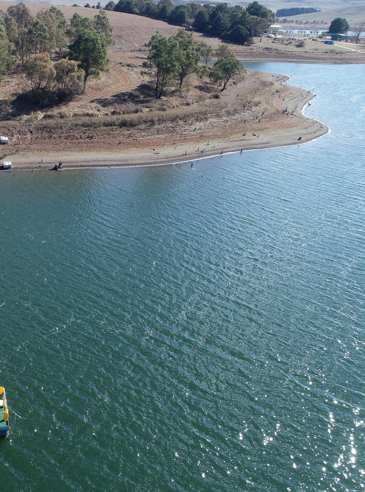
Two low-lift pumps were then set on a floating pontoon in the dam, which is able to rise and fall with the water levels, allowing pumping at variable dam levels.
“These pumps transfer water from Malpas Dam to a highlift pump station comprising six identical vertical multistage centrifugal pumps (five duty and one on standby),” Mr Murray said.
“The high-lift pump station boosts the pressure of water arriving from the low-lift pontoon sufficiently to overcome the static head and friction loss, and eventually transfers water to the Guyra Water Treatment Plant.
“The high-lift pump station operates five duty centrifugal pumps which are capable of pumping 12L/s or 60L/s when all five pumps are running at full speed. The maximum treatment capacity of Guyra Treatment Plant is 60L/s, so further expansion of the pump station is not warranted without an upgrade of the treatment plant.
“The project’s infrastructure also includes a Powdered Activated Carbon (PAC) plant. Malpas Dam has a history of occasional algal blooms and PAC dosing is essential to treat taste and odour issues.
“An electrical upgrade at Malpas Dam was also needed to raise the power supply to a required level.”
Overcoming project challenges
As with any major project, there are bound to be challenges and obstacles for contractors and project managers to overcome. Mr Murray said there were a number of challenges that needed to be mitigated to ensure a successful outcome.
“There were various critical paths in this project. The main challenges faced by the crew were: negotiation with landholders affected by the pipeline route; design approval from Essential Energy; procurement of a new voltage regulator and transformer; rock encounter; and other latent conditions during the construction phase,” Mr Murray said.
“Proper planning, site assessment and communication helped overcome all the obstacles. The major takeaway from this project was the need to allow enough time for processes beyond the Council's control.”
33 www.pumpindustry.com.au pump industry | Autumn 2020 | Issue 31 WATER


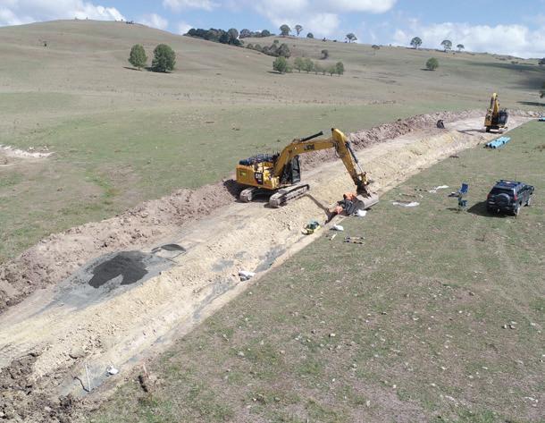
Racing to beat the drought
With the drought choking the Guyra district, time was of the essence for contractors working on the project. Dwindling water supplies meant that Guyra was on track to reach ‘day zero’ in mid 2019, giving contractors the incentive to work quickly to complete the project ahead of time.
“Construction of the pipeline was expedited because of prevailing drought conditions, with supplies in Guyra Dam on track to run out in mid 2019. While water from Malpas Dam was trucked to the Guyra treatment plant to supplement remaining Guyra Dam supplies, crews completed the pipeline ahead of schedule,” Mr Murray said.
“An official opening with Deputy Premier, John Barilaro, and the Member for Northern Tablelands, Adam Marshall, was held on schedule in October 2019.”
Maintaining the pumps
Now that the essential pipeline is online and operating, future maintenance is of the utmost importance to ensure the infrastructure copes with demand.
Mr Murray said that an ongoing maintenance plan was in place to ensure the pipeline and accompanying infrastructure remains in working order, even when the pumps are not in use.
“A daily/weekly/quarterly/annually maintenance plan is in place for the infrastructure and pumping equipment. Even when the pipeline is not in use, Council will need to run the pumps every two to four weeks to clean the pipeline and keep the pumps in working order,” Mr Murray said.
Benefitting the region for years to come
With construction now fully complete, the Armidale region is able to reap the benefits of a more flexible, secure water supply. Mr Murray said these benefits also have the potential to increase economic development and job creation in the region.
“The pipeline has brought two supply systems together to create an integrated town water supply,” Mr Murray said.
“It provides greater flexibility in sourcing water for the town supplies and enables the current system to access water from the much larger Malpas Dam.
“The increased water security provided to Guyra town water users will also open the door for substantial economic development and job creation. A number of horticultural industries have shown interest in investing in the area and are just waiting for a more reliable water supply before they commit.
“Guyra’s high number of sunny days and consistently cool conditions gives it incredible potential to become a hub of intensive glasshouse horticulture. While planning approvals would require any new agricultural developments to be primarily water self-sufficient, the Malpas Dam to Guyra pipeline would help provide greater water security during extended dry periods.”
Mr Murray said that funding has also been confirmed to improve pipeline infrastructure connecting the 700ML Puddledock Dam, providing a backup to the network when the Malpas Dam is offline.
34 pump industry | Autumn 2020 | Issue 31 www.pumpindustry.com.au
WATER
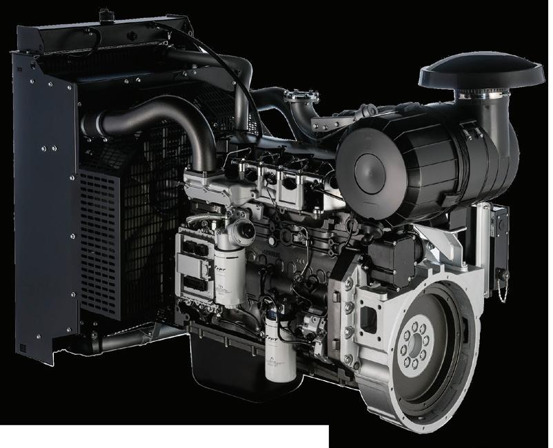

Tel: +61 (2) 9673 7777
PUMPING UP DUBBO’S ASSETS
Dubbo Regional Council in New South Wales’ Orana Region has been undertaking a range of upgrades, and water and wastewater projects across its jurisdiction to meet the demands of the community, replace aging equipment, increase water security and improve the efficiency of the site. Here, we look at some of the projects being undertaken by the council, the procurement process for the pumps, and the design and construction process.
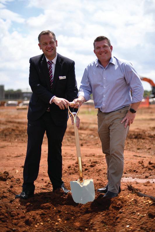
Upgrading the Mumbil Raw Water Pump Station
An upgrade to the raw water pump station in Mumbil, a small town between Wellington and Orange in Dubbo Regional Council’s jurisdiction, has required careful consideration of pumping equipment to ensure it was able to meet the changing demands of the site, while also being compatible with the existing site.
Julian Geddes, Director Infrastructure at Dubbo Regional Council, said when selecting a pump for an existing location like Mumbil, it was important to consider the existing infrastructure.
“Needs change over time and what was once a suitable solution may not be the case now. The existing pumps in Mumbil were no longer available, and another type/model was needed,” Mr Geddes said.
“The current flow rate is 7L/s into a 151m/h. The current pipework or rising main on this installation are aging pipes, so one of the considerations was not to increase the head pressure as this may lead to pipe failures.
“The water at this site is not very aggressive so corrosion is not an issue; however, in some cases like irrigation the well water can be very aggressive and can destroy a pump that is not suitable.”
Selecting pumps for projects and maintaining them
Mr Geddes said along with factors like those presented in the Mumbil Raw Water Pump Station upgrade, there are a number of other factors that are considered when selecting a pump for a project including head pressure, required flow, motor starting method, condition of water being pumped, reliability and serviceability of pumps.
As always, cost is an important consideration for all aspects of maintenance and repairs. In some cases, the right pump may have a higher installation cost, but it may be the best solution for the long term by reducing downtime from repairs and failures,” Mr Geddes said.
In order to identify issues early and reduce downtime, and to maintain efficiency levels, pumps across all Dubbo Council assets undergo a range of testing where possible, including:
• Insulation testing of the motor winding to identify issues or cable breaking down
• Flow charting – a drop in the flow can indicate pump wear and performance issues
• Onsite visual and audible testing – an audible (listening test) can pick up excess noise and may be a result of a pending mechanical failure
• Current draw – changes in the motor current can indicate issues like wear and poor pump performance
“With bore pumps, there is not a lot of preventive maintenance you can do except to monitor the pump’s output, current, flows, etc. A visual and audible inspection is a key
36 pump industry | Autumn 2020 | Issue 31 www.pumpindustry.com.au
WATER
Mayor of the Dubbo Region, Councillor Ben Shields, and Member for Dubbo Dugald Saunders turning the first sod on the truck wash.
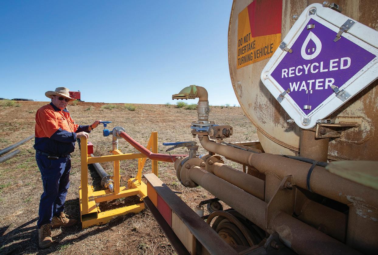
factor to picking up potential issues, and needs to be done monthly. Having good electronic monitoring systems in place is key to preventing downtime,” Mr Geddes said.
Stuart Town bore brings water security
Located within Dubbo Regional Council’s jurisdiction, Stuart Town has been experiencing water security concerns, exacerbated by the drought. To address these concerns and build community resilience, Council installed a new bore and non-potable water infrastructure for a water filling station, providing residents access to up to 60,000L a day.
Previously, Stuart Town residents relied entirely on rain water collected in tanks and water carting to supply their needs.
Installing the bore
Council drilled the bore 2km west of the town and installed a connecting pipeline that fills two 20,000L storage tanks at the new filling station adjacent to the local fire brigade shed on the corner of Burrendong Way and Copeland Street.
Chris Godfrey, Senior Design Engineer at Dubbo Regional Council, said the Federal Government provided $560,000 for the works, including completed bore equipment with a submersible pump, automatic backwash filter, electronic controls and a shed.
“The pipeline and reticulation systems for the project were designed by Dubbo Regional Council’s Design Section. The pipeline is constructed entirely from HDPE material and utilises DICL fittings in some locations. Electrofusion fittings are also utilised. The pipeline diameter varies between DN75 and DN125, and has been designed to comply with the Water Services Association of Australia (WSAA) code for potable water supplies. The pipeline has also been designed so that it can be expanded in the future, ensuring that it continues to serve the needs of the growing village of Stuart Town,” Mr Godfrey said.
“The submersible pump used for the Stuart Town bore is a Grundfos SP 7-27. It is powered by a single phase 3.7kW motor and is capable of delivering a flow rate of approximately 2L/s at a design head of 120m. The depth of the bore is approximately 84m, with the pump suction level set at 60m below the top of the well.
“A 130 micron, two inch ‘SpinKlin’ automatic self-cleaning disc filter, manufactured by Arkal, is also installed to prevent the ingress of sand and clay particles into the Stuart Town water supply. The filter continuously monitors the pressure of its inlet and outlet, and automatically backwashes when the differential between the two reaches a certain threshold.”
37 www.pumpindustry.com.au pump industry | Autumn 2020 | Issue 31 WATER
DRC has started using treated effluent in construction and roadworks areas for dust suppression.
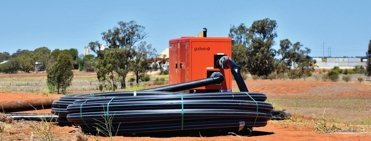
Procuring the equipment
Mr Godfrey said Council put out a tender for the construction of the pipeline component of the project with four quotations received, and the contract being awarded to local contractor PTS Group.
“Other major local contractors involved with the project included Watermin Drillers, who drilled and cased the bore; Notts Rural and Domestic, who supplied pipe materials and fittings; Aquawest, who supplied the bore pump, shed and control gear; Imrie, Astley and Associates, who provided survey information and control for the job; Macquarie Geotech, who provided geotechnical investigation for the project; Activenergy, who extended existing powerlines and supplied a new transformer and power connection to the new bore pump; and Nolan’s Earthmoving, who provided bitumen sealing services for the new water filling station hardstand area.”
Providing the community with water
Mr Godfrey said while the water is not drinkable, the new supply can be used for other things such as toilets, showering and cleaning – saving the precious resource for human consumption.
Connections are also going to be made in the near future by Dubbo Regional Council staff to the local primary school and Moxon Park, supplying these facilities with a reliable water supply.
In addition to the water filling station, spring valve fire hydrants have been installed on water mains supplied by the bore in some areas within the village, improving the level of fire protection within those areas.
Commissioning and installing a pump transfer station
The Council has commissioned and installed a new pump transfer station at the Dubbo Sewage Treatment Plant that will see the rapid fill and turnaround of water carting trucks used for dust suppression at roadworks and land development sites around the region to help reduce the burden on town water supply.
There are a number of significant works currently underway around the region that require water for dust suppression. Limiting or removing the need to use potable (drinking) water and replacing it with treated effluent was high on Council’s agenda.
Steve Colliver, Project Coordinator - Drought Coordinated Response Team, said the project was in response to a call from the Federal Government for big water users such as councils to look at innovative and smarter ways of conserving water.
Equipment to meet specifications
Mr Colliver said two key considerations during the procurement process for the equipment was that the pump had sufficient capacity to ensure a quick fill time and could be controlled remotely due to the location of the fill point in relation to the pump.
“Council purchased a Godwin NC100 100mm pump. This is capable of delivering 230m3/h or 1,013 GPM. The pump was purchased in accordance with Council’s procurement policy and the needs determined through the detailed design process,” Mr Colliver said.
A safe alternative
Mr Colliver said using treated effluent is a safe and efficient practice that has been in place for some time, and is ideal for operational use such as dust suppression and irrigation with the latter being the biggest user of Dubbo’s treated effluent.
“While treated effluent hasn’t yet made its way into the community’s everyday psyche or mainstream usage, there is absolutely no reason why a safe and plentiful water source like this shouldn’t be used to reduce the effects of dust during construction rather than use our precious drinking water supplies,” Mr Colliver said.
CEO Dubbo Regional Council, Michael McMahon, said that when people hear the phrase ‘treated effluent’ it instantly conjures up images and misconceptions in people’s minds.
“The reality is, the treated (effluent) water that Council is repurposing is actually very good and is regularly tested to ensure it is fit for purpose for alternative uses, such as these,” Mr McMahon said.
“In 2019, considering all the environmental requirements, regulations, technology and best-in-the-world practices that places like Australia employ to create treated effluent for discharge back in the system, the stigma of ‘effluent’ should be somewhat obsolete.
“Given the need and demand for water in construction, farming and industry etc, having treated effluent at-hand in times of extreme drought is a far, far better proposition than expending precious water supplies on such activities as dust suppression.”
38 pump industry | Autumn 2020 | Issue 31 www.pumpindustry.com.au WATER
Infrastructure being installed for the new pump station at the sewage treatment plant.

Improving biosecurity with a new truck wash
New water and pumping infrastructure is also being installed as part of a project to install a new truck wash at the Dubbo Regional Livestock Markets, and to increase the site’s efficiency by decreasing waiting times and allowing more efficient movement of vehicles through the wash.
Dubbo Regional Livestock Markets (DRLM) is one of the largest sale yards in the country, with more than 1.3 million sheep, 200,000 cattle, and 9,000 goats being sold annually.
Ross McCarthy, Manager Dubbo Regional Livestock Market, said that with so many animals coming from all corners of NSW and sometimes Queensland, it’s important that biosecurity standards are at their best.
“Decontaminating trucks that transport livestock is an integral part of the agricultural industry’s biosecurity measures, as it is paramount in preventing disease transmission. The Australian Bureau of Agricultural and Resources Economics and Sciences (ABARES) found that a large-scale, widespread Foot and Mouth Disease (FMD) outbreak would cripple the industry by $50 billion over ten years. The transmission and impact of a disease like FMD can be reduced significantly with decontamination procedures such as truck washing.”
Designing the truck wash
In addition to the extra wash bay, the following features will be included in the upgrade process:
• New pumps allowing a better and more constant supply of water pressure, allowing fast wash out
• More slope to allow trucks to drain quicker allowing more complete and faster wash out of trucks
• Longer facility so operators are not working in the drainage area of truck wash
• More efficient and effective lighting
• Screens between wash bays
• New screen to reduce waste for better environmental outcomes
• Cameras will be an added deterrent to unsafe behaviour and increase personal safety
Mr McCarthy said Council put out a project tender for public submission, with six businesses submitting a tender.
The successful contract was awarded to David Payne Constructions, a locally-owned and operated business in the Central West.
“The type of pumps used in this project are currently being finalised. New pumps will include one for high pressure washouts and a sump pump similar to Flygt Concertor Pump, Model NX6020.180 7.3kW, duty 40L/sec at 14m head. In addition to this, the onsite tank is 20,000L at a depth of 3.3m. There’s also stirrer/agitator included as part of the works,” Mr McCarthy said.
Constructing the truck wash
The first sod was turned on 12 February 2020, with State Member, Dugald Saunders, joining Dubbo Regional Council Mayor, Ben Shields, and DRLM Manager, Ross McCarthy. Construction is expected to be completed by the end of April 2020.
The project received $819,467 in funding from Restart NSW under round three of the NSW Government’s Fixing Country Roads Program, with total project cost projected at $1.5 million.
39 www.pumpindustry.com.au pump industry | Autumn 2020 | Issue 31 WATER
DRC truck using treated effluent at one of its roadworks locations.
AUTOMATED WATER TREATMENT PROCESS FOR INCREASED OUTPUT AND COST SAVINGS
Worldwide demand for water is increasing, while this valuable resource is becoming scarcer. The water industry relies on automated and digital concepts to treat water more efficiently, productively and competitively. Two goals are in the foreground: the safe supply/disposal as well as the economical use of resources. At the process level, Bürkert can provide support with practical solutions for the automation of ion exchangers, membrane filtration and media filtration.
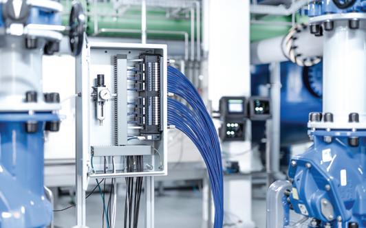
Be it process or drinking water, the construction and operation of water treatment plants places growing demands on services. Automation can be implemented in three different ways: centralised, distributed and decentralised.
Three forms of automation explored
Centralised automation: everything in one place
A central control cabinet provides an overview of your plant. It offers space for the PLC, power supply, AC actuators, I/O systems, valve islands as well as communication interfaces. The valve island enables you to control processes via a central network of multi-way pneumatic valves.
Your benefits: The plug-and-play platform cuts engineering costs. The diagnostic functions on the device and at plant control level enable you to detect errors at an early stage. Diagnostics and maintenance are service friendly and increase the availability of your plant. Easy access to manual override speeds up start up. Since the control cabinet is located outside the process, there are hardly any space restrictions and the systems can be easily extended as required.
Distributed automation: short paths
Control your plant with compact onsite control cabinets in the individual sections. Depending on the actual plant, you benefit from a number of advantages: short paths and flexible, space-saving assembly mean fast installation and safe processes. The reduced consumption of compressed air and energy is profitable in terms of speed, energy costs and efficiency. The individual process units with high valve concentrations are robust and easy to monitor and clean. Small, standardised control cabinets or field modules ensure your plant is transparent. Thanks to the process proximity, you need fewer hoses, lines and cable trays. Your automated solution can be extended easily and quickly at any time.
Decentralised automation: lean and fast switching
With this concept, each process valve is controlled individually and supplied via its own intelligent control head.
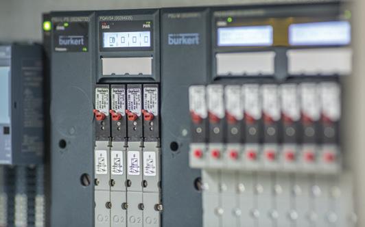
The process valves use LEDs to signal their actual switching state. This simplifies onsite process monitoring, eliminates troubleshooting and guarantees plant availability. Key advantages: the intelligent, fast-switching valve systems are particularly flexible, clearly arranged and safe. They have a hygienic, easy-to-clean design and can be quickly started up, maintained and extended. The process proximity reduces the need for compressed air, pneumatic hoses, lines and cable trays, thereby further shortening process valve switching times. This also helps to reduce your energy costs.
Regardless of the type of automation that works best for you, the task is always the same; controlling all inflows and outflows by means of pneumatic actuator and control technology.
As the fluid control experts, Bürkert begins by asking the right questions first, exploring your successes, your challenges and areas where you wish to improve or future proof processes to find the best possible solution and to decide which concept suits your plant best.
Bürkert flexibility
With the aid of numerous monitoring and diagnostic functions, Bürkert’s range of sensor technology, valve technology, pneumatics and control cabinet technology enables safe processes and preventive maintenance. You save resources, receive relevant information and benefit from the automatic documentation of your data.
Automation should make your processes simpler and more efficient. All three Bürkert concepts ensure this to an equal degree. The fieldbus module Type ME43 acts as a standardised interface for the devices. It transfers their communication to common industry standards. The technology minimises the amount of planning and installation effort, material usage and the risk of errors.
We make ideas flow.
For more information, visit www.burkert.com.au.
40 pump industry | Autumn 2020 | Issue 31 www.pumpindustry.com.au
WATER | PARTNER SOLUTIONS
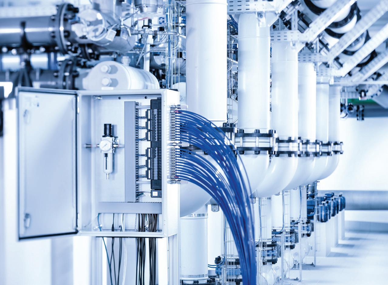


Raising the energy efficiency standards of pool pumps
New minimum energy performance (MEP) standards for swimming pool pumps will be introduced this year, making it easier for consumers to identify and purchase more energy efficient pool pumps. Here’s what pool pump manufacturers need to know about the new regulations.
There are about 1.1 million household swimming pools in Australia, and to service this growing industry around 90,000 new pumps are sold each year. The cost of running a pool pump is estimated to be around 18 per cent of a household’s energy bill. This cost is unnecessarily high because people continue to buy, install and use pool pumps that are not the most energy efficient on the market.
If a household is using a single speed pump, electricity will cost much more than the initial purchase price of the pump. Electricity bills can be reduced by buying a more energy efficient pump, even if it costs more up front. For example, a typical three star single speed pump would have a lifetime cost of around $3,900, whereas, a typically seven star variable speed pump would cost around $2,750 over its lifetime.
Reducing barriers for more efficient technology
The new regulations aim to address barriers and behaviours preventing the pool pump market from moving naturally to more efficient technologies. They will contribute to lowering unnecessarily high externality costs from pool pumps, such as greenhouse gas emissions, peak loads on electricity distribution networks and residential noise pollution.
In September 2019 – ahead of introducing MEPS levels and labelling – the Federal Government released the final report from the Review of the Greenhouse and Energy Minimum Standards Act 2012 (GEMS Act). The report includes the findings and recommendations of the independent review into the Act that was conducted throughout 2018 and 2019. The Equipment Energy Efficiency (E3) Program, the cross jurisdictional program overseeing the regulation changes, has also been working with Standards Australia to revise AS 5102.1‑2009, Performance of household electrical appliances – Swimming pool pump units, Part 1: Energy consumption and performance.
Phasing out the Voluntary Energy Rating Labelling Program (VERLP)
The VERLP began in April 2010 and is administered by the Commonwealth Department of the Environment and Energy on behalf of the E3 Program. The program was intended as a transitional step leading to the introduction of mandatory labelling and MEPS requirements, which were expected to come into force in 2012. The program enabled suppliers of swimming pool pumps to register an energy rating label to display the relative energy efficiency of their pump.
However, a consultation regulation impact statement for swimming pool pumps released in November 2016 highlighted limitations of the program, including:
• Only the most efficient pumps are registered under the program and therefore it has limited benefits for advising consumers of energy efficiency information
• After eight years of operation, most pumps sold in Australia are not registered with the program and are not labelled with energy performance information
• Although the program provides some information to consumers and there are some broader community benefits, the primary effect of the program is supporting industry advertising and marketing
• There is no evidence that the program has increased the uptake of energy efficient pumps in Australia
• Administrative arrangements for the program do not align with broader GEMS legislation and program arrangements
Once the new standards are introduced, VERLP registered pumps will no longer be valid. All products covered by the regulations will be required to be retested and reregistered, and display the mandatory label from the commencement date of the determination for swimming pool pumps. If a pool pump is registered under the VERLP and falls outside the scope of the regulation, it can no longer be registered.
WATER 42 pump industry | Autumn 2020 | Issue 31 www.pumpindustry.com.au
However, currently registered VERLP products can continue to display the voluntary label up to six months after the regulations come into effect.
New standards for energy efficiency labelling
In December 2018, the Council of Australian Governments (COAG) Energy Ministers agreed to the Decision Regulation Impact Statement (RIS) that new regulations would apply to pool pumps, requiring them to meet MEPS and display an energy rating label under the GEMS Act.
COAG Energy Ministers accepted the following recommendations:
• Apply MEPS and mandatory labelling to pool pumps that fall within the range of:
• Update the Australian standard that measures the energy efficiency of swimming pool pumps to:
» more fairly compare pump types by using a weighted energy factor
» change the scope, as shown in the table, to capture residential filtration pool pumps and exclude pool pumps used for other purposes
» amend the definition of pump classifications of single, two, multi and variable speed pumps
» make technical amendments to improve the robustness, reliability and repeatability of the test method
• Introduce a curved line star rating with higher requirements for smaller pumps and lower requirements for larger pumps to ensure that pool pumps are rated fairly
• Update the pool pump energy rating label and require the labels to be displayed either on the product, if displayed in store, or on the packaging



WATER 52 Woodlands Drive, Braeside Victoria 3195 PO Box 876, Braeside Victoria 3195 Tel: (03) 9588 6900 Fax: (03) 9588 6999 Email: info@lkdiesel.com.au Web: www.lkdiesel.com.au • Petrol engines up to 13 HP • Diesel engines up to 83 HP • Generating sets up to 30 KVA We provide diesel engine solutions to EMPOWER your business WATER PUMPS ALSO AVAILABLE
For more information and updates on the implementation of the new regulations, visit the E3 Program’s website at energyrating.gov.au/products/swimming-pool-pumps. Input power range between: Watts Amps Watts Amps Single Speed 6000 2.6 and 1,700 7.4 Two Speed 600 2.6 and 3,450 15 Multi Speed 600
15 Variable Speed 600
43 www.pumpindustry.com.au pump industry | Autumn 2020 | Issue 31
2.6 and 3,450
2.6 and 3,450 15
GUARANTEED CONTROL AND MAXIMUM SYSTEM EFFICIENCY

Designed to drive centrifugal and submersible pumps, the new CFW500 Solar Pump Drive turns solar energy, provided from photoelectric panels, into hydraulic energy, bringing great efficiency and maximising system availability. It also offers automatic control of pump starting and stopping, depending on the availability of solar energy or pressure level.
Main Characteristics:
• Continuous maximum power point tracking (MPPT)
• Double PID for simultaneously controlling of both DC voltage and pipeline pressure
• Counter for working hours and generated kWh indication
• Up to four distinct speed and pressure setpoints
• Sleep/Wake up function triggered by DC voltage or pipeline pressure
• Hybrid power source available1 (solar panels + gensets) to increase the available operational time for periods of low solar irradiation
• Scalar or Vector control
1 Requires solar irradiation sensor

• Modbus-RTU RS485 communication
• Side-by-side mounting possible
• Dry pump protection
• Overpressure and broken pipe protection
• Simple programming
• Available for ambient temperature up to 50°C without derating. Maximum ambient temperature of 60°C with derating
• Possibility to operate in off-grid systems
• Smart thermal management
• Automatic MPPT (Maximum Power Point Tracking) efficiency higher than 99 per cent
44 pump industry | Autumn 2020 | Issue 31 www.pumpindustry.com.au
MOTORS, DRIVES AND ENGINES | PARTNER SOLUTIONS
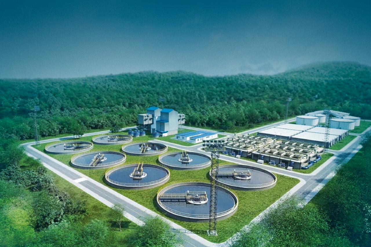
Robust 150% overcurrent for 60 seconds and ambient temperature up to 50 °C. Benefits
Reliability Products 100% tested.
Customizable SoftPLC functions.
WA 08 9400 5700 wasales@weg.com.au

VIC / SA / TAS 03 9765 4600
vicsales@weg.com.au sasales@weg.com.au

Double PID Control DC voltage control with maximum power point tracking (MPPT) and pipeline pressure control through pressure sensor.
QLD / NT 07 3265 9800 qldsales@weg.com.au
Tropicalized Electronic Boards
Enhance lifetime, protecting electronic circuit in harmful environments. Class 3C2 of standard IEC 60721-3-3.
NSW 02 9616 3900 nswsales@weg.com.au
Motors | Automation | Energy | Transmission & Distribution 2915 C Pantone 2925 C Pantone CMYK 80/20/0/10 284 C Pantone CMYK 60/0/0/10 CMYK 40/0/0/10 CMYK 0/0/0/0 2945 C Pantone CMYK 100/60/0/10 542 C Pantone CMYK 60/20/0/0 Compact Off-Grid Systems Simplified Setup and Installation State-ofthe-Art Energy Saving
SoftPLC
LUBRICATION UPDATE FOR ELECTRIC MOTORS
By Heinz P. Bloch, PE, Process Machinery Consulting
Australia’s largest oil refinery, BP’s Kwinana, is among the best-of-class refineries using oil mist lubrication on machinery with rolling element bearings. In its process pumps, the refinery has enjoyed the benefits of oil mist technology for many years; a recent report mentioned an MTBF (mean-time-between failure) somewhere between 114 to 120 months. As of early 2019, they still haven't had a lubrication-related bearing failure since 1999. The facility’s ACHE (air-cooled heat exchanger) fan bearings haven't been touched since installation in 2004. The same 15-years-and-still-going feedback was obtained for plummer block bearings in BP’s Kwinana’s ID (induced draft) and FD (forced draft) fans.
API610, the most widely used pump standard in the petrochemical and refining industries, includes experience-based recommendations for lubricant application, and one of these relates to oil mist. The API standard asks for oil mist to be routed through the bearings (Figure 1).
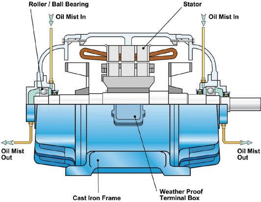
UK and
Tennessee, US).
Although intended for pumps, this same recommendation will work equally well for electric motor rolling element bearings. The resulting diagonal through flow route guarantees adequate lubrication, whereas oil mist entering and exiting on the same side might allow some of the mist to leave without first wetting the rolling elements. Through-flow is thus one of the keys to a successful installation. This article addresses how oil mist lubrication is widely used for electric motors.
Major electric motor manufacturers, including the former Reliance Electric Company (Cleveland, Ohio), were fully aware of this fact. Representing “best technology,” their mid1970s bearing housings were configured for through-flow. Moreover, a very wide oil mist suitability range is documented for electric motors. Industrial giant Siemens has, years ago, published technical bulletins showing pure oil mist as a superior technique for electric motors ranging in size from 18 to 3000kW.
Bearing size constraints and synthetic lubricants for electric motors
Decades of experience confirms the success of oil mist for rolling element bearings in the operating speed and size ranges found in motors for process pumps.
Since about 1960, empirical data have been employed to screen the applicability of oil mist. The influences of bearing size, speed and load have been recognised in a rule-of-thumb oil mist applicability formula, limiting the parameter “DNL” (D = bearing bore, mm; N = inner ring rpm; and L = load, lbs) to values below 10^9, or 1,000,000,000. An 80mm electric motor bearing, operating at 3,600 rpm and a load of 600lbs, would thus have a DNL of 172,000,000 – less than 18 per cent of the allowable threshold value.
As of 2019, approximately 50,000 oil mist lubricated electric motors are operating flawlessly in reliability-focused user plants.
Capitalising on this favourable experience, the procurement specifications for both new projects and replacement motors (with rolling element bearings) at many of these plants require oil mist lubrication in sizes 15kW and larger.
Although it was well known that synthetic lubes reduce friction, little quantitative work had been done before 1980. Morrison, Zielinski and James1 quantified how diester-based lubricants reduce the frictional power losses of industrial equipment; their findings are summarised in Tables 1 and 2.
1 Morrison, F R, Zielinsky, J and James, R 1982, ‘Effects of synthetic fluids on ball bearing performance, Transactions of the ASME, Journal of Energy Resource Technology, vol. 104, pp. 174–181
2 Pinkus, O, Decker, O and Wilcock D F 1997, ‘How to save 5% of our energy’, Mechanical Engineering, September
46 pump industry | Autumn 2020 | Issue 31 www.pumpindustry.com.au
MOTORS, DRIVES AND ENGINES
Figure 1: Oil mist applied to electric motor bearings (Source: AESSEAL, Inc., Rotherham,
Rockford,
3
Table 1: Overview of power loss with different oils and application methods1
Sump
Sump SYN 32 to Mist SYN 32 0.085 31%
Sump MIN 68 to Mist SYN 32 0.11 38%
Table 2: Overview of power loss and loss reduction percentages with different oils and application methods1.
The potential cost savings through power loss reduction are quite substantial. It has been estimated that industrial machines consume 31 per cent of the total energy in the US2 As much as five per cent of the mechanical losses of these machines could be avoided through a combination of improved equipment design and lubricant optimisation.
Motor sealing
Motor sealing and mist drainage are well understood. Although oil mist will neither attack nor degrade the epoxy insulation on electric motor windings manufactured since the mid-1960s, mist entry and related sealing issues merit inclusion in this overview.
Regardless of motor type, i.e. TEFC, X-Proof or WP ll, cable terminations in junction boxes should not be made with conventional electrician’s tape. The adhesive in this tape will last but a few days and then become tacky to the point of unravelling. Inferior products are replaced by superior materials; these are often Teflon®-based. For termination leads (“T-Leads”), competent motor manufacturers use an irradiation cross-linked polymeric insulation system that is highly resistant to oil mist.
To date, irradiation cross-linked polymeric insulation systems have consistently outperformed the many other “almost equivalent” systems.
Similarly, and while it must always be pointed out that oil mist is neither a flammable nor explosive mixture, it would be unsightly to allow a visible plume of mist to escape from the junction box cover. The wire passage from the motor interior to the junction box should, therefore, be sealed with 3M ScotchCast Two-Part Epoxy potting compound. Doing so will exclude oil mist from entering the junction box.
Finally, it is always good practice to verify that all electric motors have a small (3mm) weep hole and that XP-motor drains are given closer attention. The latter are furnished with either an explosion-proof rated vent or a suitably routed weep hole passage at the bottom of the motor casing or lower edge of the motor end cover. Intended to drain accumulated moisture condensation, the vent or weep hole passage will allow coalesced or atomised oil mist to escape.
Note, however, that explosion-proof motors are still “explosion-proof” with this passage. Reasoning on the issue should convince us that a motor with its interior slightly pressurized (to 0.1–0.3 psi above ambient) by non-explosive oil
mist cannot ingest any explosive vapours from a surrounding atmosphere. The suitability of oil mist for Class 1, Group C and D locations was specifically re-affirmed by Reliance Electric in July of 2004.
TEFC vs WP ll construction
On TEFC (totally enclosed, fan-cooled) motors, there are documented events of liquid oil filling the motor housing to the point of near contact with the spinning rotor. Conventional wisdom to the contrary, there neither were, nor will there be, detrimental effects with the oils used in normal industry; the motors could have run indefinitely.
TEFC motors are suitable for oil mist lubrication by simply routing the oil mist through the bearing, as has been explained in a comprehensive text on lubrication. There are numerous other references, including API610. No special internal sealing provisions are needed with pure oil mist filling a TEFC motor so long as the pressurised mist keeps dirty atmospheric air from entering.
On weather-protected (WP ll) motors, merely adding oil mist has often been done and has generally worked surprisingly well. In this instance, however, it was found important to lead the oil mist vent tubing away from regions influenced by the motor fan. Still, weather-protected (WP ll) electric motors do receive additional attention from reliability-focused users and knowledgeable motor manufacturers.
Air is constantly being forced through the windings and an oil film deposited on the windings could invite dirt accumulation. To reduce the risk of dirt accumulation, suitable means of sealing should be provided between the motor bearings and the motor interior.
Since V-rings and other elastomeric contact seals are subject to wear, low friction face seals are considered technically superior. The axial closing force on these seals could be provided either by springs or small permanent magnets3. Also, many modern motors use advanced rotating labyrinth seals with closure O-rings that travel axially4.*
As is so often the case, the user is asked to make intelligent choices. Some low friction axial seals (face seals) may require machining of the motor end caps, but long motor life and the avoidance of maintenance costs will make up for the added expense. Double V-rings using Nitrile® or Viton® elastomeric material are sometimes used because they are considerably less expensive than face seals.
Sealing to avoid stray mist stressing the environment
Even when still allowed under prevailing regulatory environmental regulations (e.g. OSHA or EPA), air quality and environmental concerns make it desirable to minimise stray oil mist emissions. It is helpful to recall that state-of-art oil mist systems are fully closed, i.e. are configured so as not to permit any mist to escape. The various bearing housings are sealed with the magnetic seals incorporated in the motor end bells in Figure 1; alternatively, advanced rotating labyrinth seals could be installed
Combining effective seals and a closed oil mist lubrication system has, for many decades, represented a well-proven solution. The combination not only eliminates virtually all stray mist and oil leakage, but makes possible the recovery, subsequent purification, and re-use of perhaps 97 per cent of the oil. These recovery rates make the use of more expensive, superior quality synthetic lubricants economically attractive.
47 www.pumpindustry.com.au pump industry | Autumn 2020 | Issue 31 MOTORS, DRIVES AND ENGINES
5
Bloch, Heinz P 2009, Practical Lubrication for Industrial Facilities, 2nd ed., The Fairmont Press, Lilburn, GA
4
HP In Reliability Column, Hydrocarbon Processing, July 2006; Bloch, H P 2011, Pump Wisdom: Problem Solving for Operators and Specialists, John Wiley & Sons, Hoboken, NJ
Power loss per bearing (KW)
= 8.9 KN (2000 lbf) Oil Sump Oil Mist MIN 68 0.271 0.192 SYN 32 0.254 0.169
loss per bearing Total reduction
L
Change Δ Power
6%
Sump:MIN 68 to SYN 32 0.017
Mist: MIN 68 to SYN 32 0.022 8%
MIN 68 to Mist MIN 68 0.080 29%
For many years PAO and diester-based “synthetic” lubricants have proved to embody most of the properties needed for extended bearing life and greatest operating efficiency. These oils excel in the areas of bearing temperature and friction energy reduction. It is not difficult to show relatively rapid returns on investment for these lubricants, especially when the system is closed and the lubricant is being reused after filtration6
Closed systems and oil mist lubricated electric motors give reliability-focused users several important advantages:
• Compliance with current and future environmental regulations
• Extended bearing life and reduced electric motor maintenance budgets
• The technical and economic justification to apply highperformance synthetic oils
PAO and diester-based “synthetic” lubricants embody most of the properties needed for extended bearing life and greatest operating efficiency. These oils excel in the areas of bearing temperature reduction (Figure 2) and friction energy reduction (Figure 3).
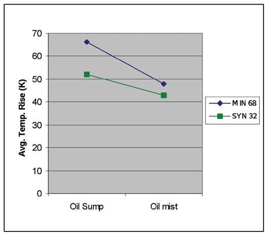
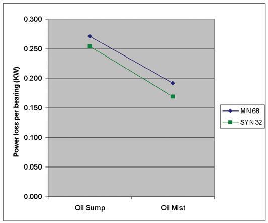
A composite plot of different changes and power reduction percentages is given in Figure 4. It is not difficult to show relatively rapid returns on investment for these lubricants, especially for closed systems where the lubricant is reused after filtration.
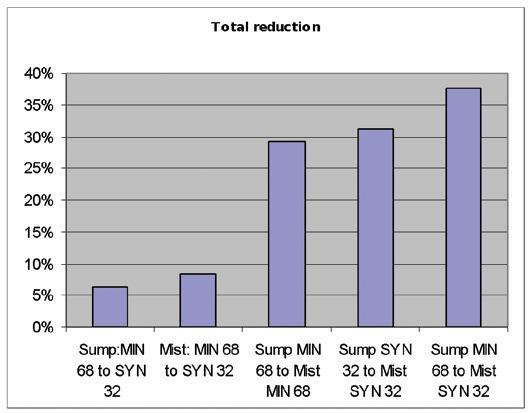
Converting grease-lubricated electric motors to pure oil mist.
When converting operating motors from grease lubrication to oil mist lubrication, consider the following measures in addition to the above:
a. Perform a complete vibration analysis. This will confirm or rule out pre-existing bearing distress and will indicate if such work as re-alignment or base plate stiffening is needed to avert incipient bearing failure
b. Measure the actual efficiency of the motor. If the motor is inefficient, consider replacing it with a modern highefficiency motor, using oil mist lubrication in line with the above recommendations. This will allow capture of all benefits and will result in greatly enhanced return on investment
c. Evaluate if the capacity of the motor is the most suitable for the application. “Most suitable” typically implies driven loads that represent 75 per cent to 95 per cent of nominal motor capacity. The result: Operation at best efficiency
Note that converting an overloaded, hot-running electric motor to oil mist lubrication will lead to marginal improvement at best.
The required volume of oil mist is often expressed in “bearing-inches” or “BIs”. A bearing-inch is the volume of oil mist needed to satisfy the demands of a row of rolling elements in a one-inch (~25mm) bore diameter bearing. One BI assumes a rate of mist containing 0.01 fl. oz., or 0.3ml, of oil per hour.
Certain other factors may have to be considered to determine the needed oil mist flow and these are known to oil mist providers and bearing manufacturers. The various factors are also extensively documented in several references; they are readily summarised as:
a. Type of bearing. The different internal geometries of different types of contact (point contact at ball bearings and linear contacts at roller bearings), amount of sliding contacts (between rolling elements and raceways, cages,
48 pump industry | Autumn 2020 | Issue 31 www.pumpindustry.com.au MOTORS, DRIVES AND ENGINES
5 ibid 6 Bloch,
2009, Practical Lubrication for Industrial Facilities, 2nd ed., The Fairmont Press,
GA
Heinz P
Lilburn,
Figure 3: Power loss plot for the ball bearing test of Tables 1 & 2. Note that two
different oils are used at two different viscosities1.
Figure 2: Average temperature rise plot for the ball bearing test of footnote one.
Figure 4: Plot of different changes and power reduction percentages that resulted1.
flanges or guide rings), angle of contact between rolling elements and raceways, and prevailing load on rolling elements. The most common bearing types in electrical motors are deep groove ball bearings, cylindrical roller bearings and angular contact ball bearings
b. Number of rows of rolling elements. Multiple row bearing or paired bearing arrangements require a simple multiplier to quantify the volume of mist flow
c. Size of the bearings, related to the shaft diameter –inherent in the expression “bearing-inches”
d. The rotating speed. The influence of the rotating speed should not be considered as a linear function. It can be linear for a certain intermediate speed range, but at lower and higher speeds the oil requirements in the contact regions may differ from straight linearity
e. Bearing load conditions (preload, minimum or even less than minimum load, heavy axial loads, etc.)
f. Cage design. Different cage designs may affect mist flow in different ways. It has been reasoned that stamped (pressed) metal cages, polyamide cages or machined metal cages might produce different degrees of turbulence. While different rates of turbulence may cause different amounts of oil to “plate out” on the various bearing components, the concern vanishes when oil mist is applied in through-flow mode
Using the right bearing and a correct installation procedure
Very significant increases in bearing life and overall electric motor reliability have been repeatedly documented in the half century since 1960. Of course, oil mist cannot eliminate basic bearing problems. It can, however, provide one of the best and most reliable means of lubricant application. Bearings must be:
• Adequate for the application, i.e. deep groove ball bearings for coupled drives, cylindrical roller bearing to support high radial loads in certain belt drives, or angular contact ball bearings to support the axial (constant) loads in vertical motor applications
• Incorporating correct bearing-internal clearances
• Mounted with correct shaft and housing fits
• Carefully and correctly handled, using tools that will avoid damage
• Correctly assembled and fitted to the motor caps, carefully avoiding misalignment or skewing
• Part of a correctly installed motor, avoiding shaft
misalignment and soft foot, or bearing damage incurred while mounting either the coupling or drive pulley
• Subjected to a vibration spectrum analysis. This will indicate the lubrication condition as regards lubricating film, bearing condition (possible bearing damage) and general equipment condition, including misalignment, lack of support (soft foot), unbalance, etc.
Sealing to avoid stray mist stressing the environment
Closed systems and oil mist lubricated electric motors give reliability-focused users several important advantages:
• Compliance with current and future environmental regulations
• Convincing proof that oil mist lubrication benefits electric motors and the maintenance budget
• The technical and economic justification to apply highperformance synthetic oils
Since the 1980s, modern additives technology has further strengthened wear protection and offers reduced energy consumption with other synthetic base oils and without requiring reductions in viscosity. All are worthy of your consideration.
*It should be noted that the author does not advocate rotating labyrinth seals with O rings that could potentially make contact with sharp edged grooves.
Heinz P. Bloch resides in Montgomery, Texas.
His professional career commenced in 1962 and included long-term assignments as Exxon Chemical’s Regional Machinery Specialist for the United States. He has authored or co-written over 760 publications, among them 21 comprehensive books on practical machinery management and failure analysis. His latest book, ISBN 978-1-941872-7, is titled “Optimized Equipment Lubrication, Oil Mist Technology and Storage Preservation.” He is one of 10 inaugural inductees into the New Jersey Institute of Engineering’s Hall of Fame, which honors its most distinguished alumni.
Lowara has an extensive range of pumps and pressure systems suitable for commercial buildings, homes, general industries, agriculture and irrigation.
Reliable, high performance, quality materials, and the widespread Lowara support network make these pumps an ideal selection for your water supply requirements.
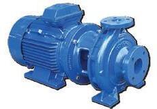

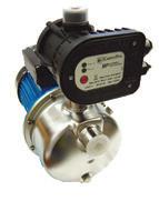

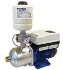
49 www.pumpindustry.com.au pump industry | Autumn 2020 | Issue 31 MOTORS, DRIVES AND ENGINES
Ph: 1300 4 BBENG www.brownbros.com.au Call us today to see how we can deliver your
pumping solution.
DELIVERING PUMPING SOLUTIONS 02/20
Industry 4.0: the implications for industrial motor control
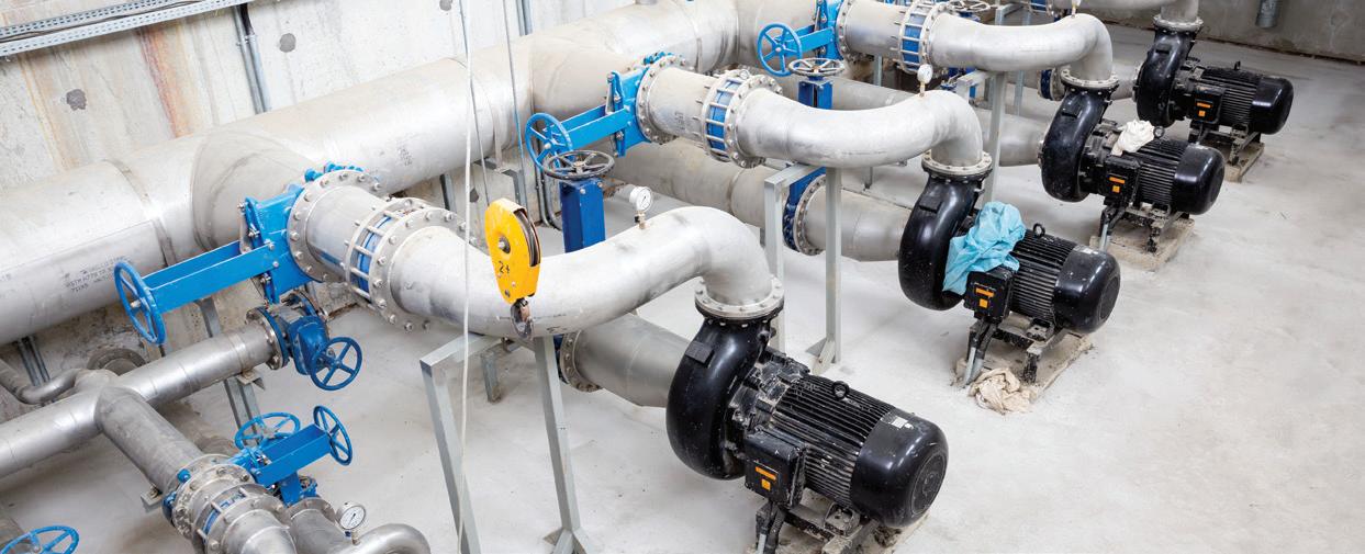
Industry 4.0 is ushering in a new era for industry, with more intelligence and connectivity, combining machines, computers and the internet to make systems smarter. This has implications for industrial motor control, especially for mature technologies like soft starters.
With the right technical capability (e.g. interchangeable smart processor cards), soft starters can control a whole system by connecting directly to other devices such as pressure, flow and depth sensors in a pumping application.
They can also become more efficient. According to the International Energy Agency, electric motors account for 69 per cent of total industrial electricity consumption in the world. Reducing this consumption is important. Around 80 per cent of motor applications are most effective with fixed speed. Selecting the correct control mode for the application (fixed or variable speed) is critical for true energy efficiency.
Embracing more energy efficient motors
Engineers are embracing the use of new generation ‘premium efficiency’ motors. IE3 motors are more efficient than IE2 motors, resulting in lower lifetime energy usage and energy costs, which has obvious value. However, other IE3 motor characteristics are affected by the changes made to achieve this efficiency.
This includes starting issues such as higher inrush and starting currents
that stress electrical supply circuits, and spiky pull out torque curves that can make smooth control of acceleration and deceleration more difficult.
Soft starters can address this by limiting inrush and starting current to the minimum necessary to start, which enables design of efficient distribution circuits and prevents breaker trip due to motor starting. Soft starters also precisely control the starting and stopping of IE3 motors, offering control over acceleration and deceleration to cater for motors with tough torque curves.
An internally bypassed soft starter is 99.5 per cent efficient when running, which equates to a potential 80 per cent reduction in waste energy compared to a misapplied variable speed drive. It also produces no harmonics during run, improving overall power quality and eliminating system losses resulting from harmonics.
More than energy savings
In addition to energy savings, Industry 4.0-ready soft starters offer: Ease of use for technical staff: A graphical display with multiple languages and in-built intelligence such as application setup menus make
installation and commissioning easier and faster. The ability to replicate these settings across multiple starters by extracting parameter information using a standard protocol like USB is also important.
Ability to extract and share data: Connecting with other devices and support services must be straightforward, including a range of communications modules enabling network connections. Mobile technology is also being leveraged by soft starter manufacturers, with smartphone app access to extracting starter and performance information for analysis and sharing.
Automation capabilities: Built-in timers and schedulers improve system efficiency and allow operations to be tailored to a site’s requirements. Automatic resets and flexible protection options can be programmed to eliminate manual interventions and ensure continued operation.
Operational reliability: This includes starter, motor and system protection functions and associated notification and alarm capability, and features like emergency override to suppress all protections for a situation when the machine simply has to run.
50 pump industry | Autumn 2020 | Issue 31 www.pumpindustry.com.au
MOTORS, DRIVES AND ENGINES | PARTNER SOLUTIONS
Soft Starters
Fully featured motor control solutions
AuCom’s EMX4i now available in the full range of current ratings
And now introducing 1000V soft starters to the EMX4i range
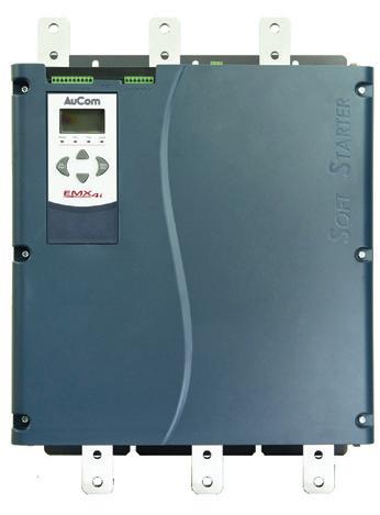
Features
• XLR-8 control to prevent water hammer
• Emergency run mode
• Real time metering & monitoring
• Automated pump clean function
• Extended motor protection functionality
• Clock & calendar scheduling

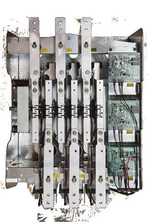
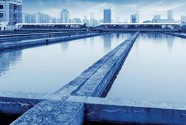



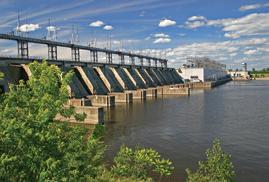
Power Distribution | Power Monitoring | Industrial Control | Photovoltaic | Installation & Accessories | Test & Measurement | Services National Customer Support Centre 43 Newton Road | Wetherill Park | NSW 2164 Tel: 1300 556 601 | Fax: 1300 550 187 Email: customerservice@ipd.com.au | www.ipd.com.au End to End Service Capabilities Custom DB Manufacturing Facility National Customer Support Dedicated Training Facility
The pumps helping NSW beat transmission losses
For towns and cities that rely on surface water sources, transmission losses can result in water supply issues, especially when inflows are low. This was a major problem for drought-hit Tamworth, in northeast New South Wales, where it resulted in almost double the town’s annual water demand to be lost. With the devastating drought threatening residents and businesses, WaterNSW is constructing a permanent pipeline and pumping infrastructure, which will provide a long-term solution to reduce losses and help Tamworth survive the drought.
By Eliza Booth, Assistant Editor, Pump Industry magazine
Residents and businesses in the regional township of Tamworth have always relied primarily on surface water from the Chaffey Dam, which made its way to the Calala Water Treatment Plant via the Peel River. The issue with relying on surface water supplies from the dam is that there can be large transmission losses as the water makes its way down the river, resulting in losses of up to 17,000ML per year, or almost double Tamworth’s annual water demand.
Without a viable groundwater source to supplement the town’s supply, and with deteriorating reliability of water due to the drought, WaterNSW decided to undertake drought protection works to limit the amount of transmission losses and to assist in extending vital water supply while a permanent, long-term pipeline solution is constructed. A secure solution for Tamworth
It became clear to WaterNSW and Tamworth Regional Council that without drought protection works in place, and with the absence of significant rainfall, residents, businesses and landholders were at risk of running out of water by mid-2020.
“There have been unprecedented low inflows into Chaffey Dam which supplies water to the city of Tamworth. The Peel Drought Relief Project will ensure Tamworth does not run out of water should the severe drought conditions continue into 2020,” a spokesperson for WaterNSW said.
The spokesperson said the drought relief project includes two stages of works, incorporating both short and longterm infrastructure to secure water supply for current and future needs.
Stage 1 works were completed on 2 December 2019 and included the construction of a temporary weir on the Peel River at Dungowan.
“This weir will redirect river water via the existing Dungowan to Tamworth Water Pipeline for transportation to Tamworth City Council’s water treatment plant at Calala, reducing transmission losses the water would experience had it traveled the full distance of the Peel River into Tamworth,” the WaterNSW spokesperson said.
MOTORS, DRIVES AND ENGINES 52 pump industry | Autumn 2020 | Issue 31 www.pumpindustry.com.au

This stage of the project also included the construction of vital intake infrastructure to assist in diverting water to the Tamworth Water Treatment Plant. This infrastructure will now remain in place while the long-term solution is being constructed in Stage 2 of the project.
Stage 2 of the drought protection works include the construction of a new 18.2km permanent (710mm) HDPE pipeline connecting Chaffey Dam to the existing Dungowan to Tamworth Water Pipeline.
“This will eliminate the significant losses along the Peel River due to evaporation and seepage, conserve the remaining storage in Chaffey Dam, and therefore prolong water supplies for the critical human needs of Tamworth,” the WaterNSW spokesperson said.

Selecting a contractor
Selecting a contractor is an important part of every project and it was essential that WaterNSW chose the right team who could achieve a successful outcome while also working in tight timeframes.
The spokesperson said WaterNSW engaged pipeline construction contractor MPC Kinetic to design, procure and build all elements of the Stage 1 and 2 project scopes.
“MPC Kinetic self-performed all pipeline design, construction and commissioning scopes, but went to the market for the Stage 1 Temporary and Stage 2 permanent pump station scopes,” the WaterNSW spokesperson said.
MOTORS, DRIVES AND ENGINES
53 www.pumpindustry.com.au pump industry | Autumn 2020 | Issue 31

“These scopes included pump station construction, pump supply and all associated electrical and civil installations.”
When it came to equipment selection for the project, a spokesperson for MPC Kinetic said that the ability to meet the extremely tight timeframe the project demanded was a critical factor in choosing suppliers.
Constructing the weir and pump station
With the right contractor selected, Stage 1 works powered ahead, with the construction of the temporary weir and associated pumping and pipeline infrastructure quickly being constructed on the banks of the diminishing Peel River.
“The Stage 1 temporary works included construction of a temporary weir made of prefabricated concrete box culverts across the Peel River, the installation of three large temporary pumps, and construction of an above ground temporary 500m-long (500mm) HDPE pipeline to interconnect into the existing Dungowan to Tamworth Water Pipeline,” the WaterNSW spokesperson said.
“The temporary pump station was constructed on the banks of the Peel River next to the Dungowan Showgrounds alongside the temporary weir. It consisted of two 125L per second (10.8ML/day) main pumps and one 125L per second (10.8ML/d) backup pump. All pumps had individual capacity to provide up to 12ML per day to ensure Tamworth received its required water supply of 21.6ML per day.”
The right pumps to handle demand
In order to ensure Tamworth would receive its required daily water supply while the permanent pipeline was being constructed, the temporary weir and accompanying pump station needed to be able to keep up with demand from the water treatment plant.
“The temporary Stage 1 works are required to deliver up to 21.6ML/d to the Calala Water Treatment Plant,” the WaterNSW spokesperson said.
“This is achieved by pumping into the existing Dungowan to Tamworth Water Pipeline which has a break tank at a high point
prior to the water treatment plant, from which point supply gravitates to Calala.
“When the treatment plant calls for water, the water level in the break tank drops. Demand through the treatment plant varies from approximately 21.6ML/d to 10.4ML/d. The Stage 1 pumps ramp up and down to maintain the water level in the break tank within a certain range, which requires them to operate with variable flow capability.”
In order to facilitate the need for variable flow capability, WaterNSW employed the use of three diesel engine pumps which have been programmed to ramp their speed up and down to match flow being called at the treatment plan.
The spokesperson said these pumps acted similar to pumps driven by variable speed motors, allowing the smooth flow of water into the treatment plant and onto the town.
Powering through Stage 2
With the Stage 1 temporary weir and pump station successfully completed and operating, Stage 2 of the project could begin. The spokesperson said that most of the construction for the long-term pipeline has been completed so far and is on track to be finished on time.
“MPC Kinetic has made significant progress on Stage 2. As of Thursday, March 5, 85 per cent of the pipeline has been constructed and buried,” the spokesperson said.
“Construction crews have also completed 65 per cent of the Stage 2 pump station scope and the entire project will be completed on schedule by April 2020.”
In the meantime, maintenance and operation of the temporary pump station remains a vital part of ensuring Tamworth remains well supplied with water.
“WaterNSW, the Tamworth City Council and construction contractor MPC Kinetic, are collaborating on the 24-hour operation of the temporary pump station, while Stage 2 project works are being progressed,” the WaterNSW spokesperson said.
54 pump industry | Autumn 2020 | Issue 31 www.pumpindustry.com.au
MOTORS, DRIVES AND ENGINES
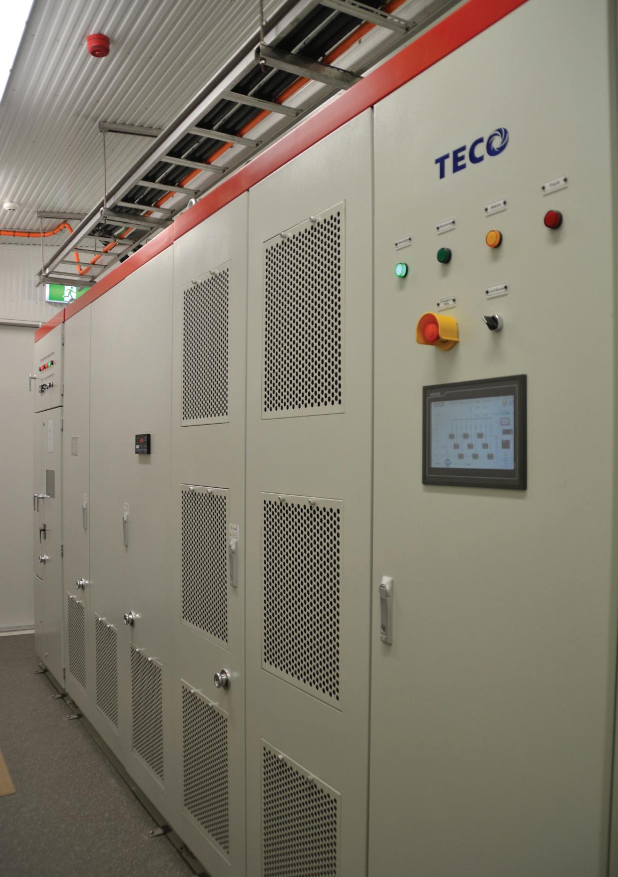
Not just motors: the high-reliability TECO MV510 VSD range
TECO Electric and Machinery is a market leader, well known for producing high-quality motors. Unsatisfied with producing only motors, TECO committed to the manufacture of motor drives over 20 years ago. In 2016, the company launched the TECO MV510 range of medium and high voltage drives that showcases its manufacturing prowess.
TECO moved from investor-supplier to owner-supplier when it acquired Westinghouse Motor Company in 1995, which strengthened its core business, increased competition and solidified its global brand leadership.
Since then, it has successfully diversified into a conglomerate with worldwide business operations covering five continents, and has become the one of world’s largest manufacturer of industrial motors.
TECO drives and motors are used in a variety of applications including industrial automation, industrial machinery, air conditioning systems, mining, oil and gas, energy-saving projects, pipelines, and wastewater treatment.
Meeting international standards
The MV510 range of drives is in compliance with global specifications for energy efficiency and environmental protection. The comprehensive portfolio ranges from 200–8,000kW, boasts power-unit connection overlapped-wave technology, and is capable of lowering damage to the insulated stress of a motors copper wire dv/dt and providing timely monitoring of operational status.
Options of IP31 and IP42 grade protections are available, plus RS485 interface, various communications formats – such as Modbus, Profibus, Devicenet, and Ethernet – and passage of CE and IEC certifications.
The power supply input and output of MV510 general medium voltage drive meet the most stringent IEEE 5191992 and GB/T14549 1993 standards, so there is no need for an independent input filter, saving customers the cost for harmonic elimination.
Because of the high power factor of the system, the compensation device for power factor is not needed, thus the reactive input and the input capacity are reduced, and the cost for capacity increasing the power network is minimised.
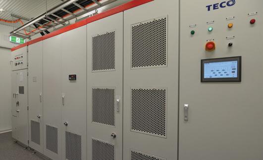
A cut above the rest
Compared with other high voltage and high power MVDs, the MV510 has a number of significant advantages. Firstly, there is no need for extra output filtering devices or direct driving of the general high voltage synchronous or asynchronous motor, and the temperature of the motor will not increase. There is also no need for motor derating operation, and no dv/dt damage will occur to the motor and cable insulation.
Due to the modular design of the power cell, it is quite simple to replace it and moreover, only a few spare parts are necessary. The power cells are universal and can be used in drives of the same current rating, regardless of voltage class. Other functions and features include:
• Protection of overload and overcurrent
• Protection of open phase and grounding
• Protection of overvoltage
• Overheat protection
• Current limited function
• Interlock protection of control power supply
• Two sets of control power for redundancy power cell bypass function (optional)
• Motor Bypass System (optional)
• Frozen-charge
• Cabinet door opening alarm function
• Lock-phase function
• Synchronising switch function between variable frequency and work frequency
• Soft start of motors, no impact to mechanical equipment and network
• IoT – Internet of Things With units already being sold, the TECO MV510 range of drives is making a significant contribution to the motor and drive market.
MOTORS, DRIVES AND ENGINES | PARTNER SOLUTIONS
For more information about the TECO MV510 range of drives, visit our brand new website www.teco.com.au
Caprari presents the new EASYWELL MPC10 motor
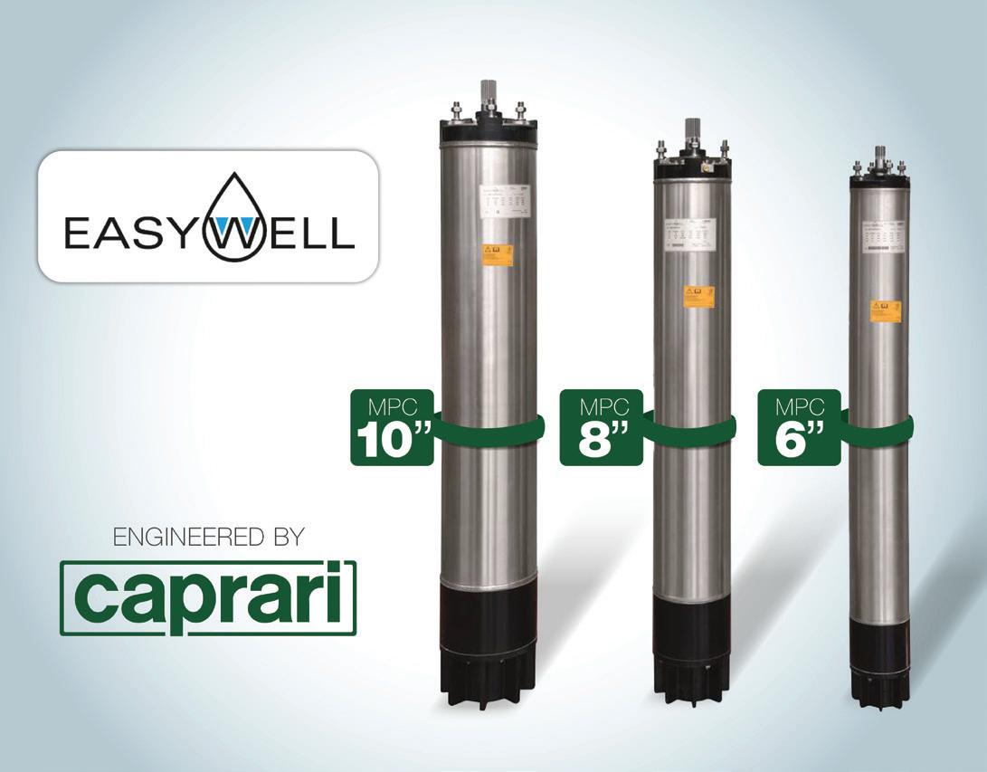
The MPC10 motor, engineered by Caprari SpA, has been launched onto the market to complete the MPC6 and MPC8 range, thus offering customers particularly well-performing products that stand out for their extremely low energy consumption compared to the industry average, at a very competitive price.
The new MPC10 model can be used for a broad range of applications, even the most challenging ones.
Perfect for the agriculture industry, the EASYWELL range features outstanding resistance to wear. Due to the mechanical silicon carbide seal, it is also suitable for heavy duty operations where abrasive liquids are present, and ensures remarkable resistance to thermal shock and aggressive chemicals.
The MPC10 motor is particularly sturdy and reliable thanks to graphite-based, self-lubricating, composite material line bearings and a thrust bearing whose oversize is amply
suited to withstand the axial loads generated by the wet end. Moreover, the copper rotor and the large stacks ensure excellent, top-level electrical performance and efficiency that exceed the average of its competitors.
The innovative MPC10 is suitable for applications with VSDs (variable speed drives), and is available in AISI 316 full stainless steel versions (MPCW10).
Caprari used its experience to create a motor that is innovative and reliable, providing customers new opportunities, while reducing return on investment time. Caprari borehole pumps and EASYWELL motors ensure a very high level of efficiency.
As well as being competitively priced, MPC10 motors have reduced energy consumption and environmental impact.
The EASYWELL series represents a reliable alternative to MAC submersible motors – Caprari’s exclusive design for top performing and heavy duty applications.
Caprari’s customers rely on one of the most complete lines of borehole pumps and submersible motors ever.
The 6”, 8” and 10” MPC EASYWELL range is available at www.caprari.com.
56 pump industry | Autumn 2020 | Issue 31 www.pumpindustry.com.au
MOTORS, DRIVES AND ENGINES | PARTNER SOLUTIONS
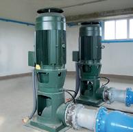
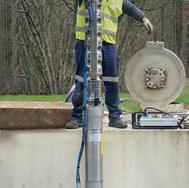



DRINK RELIABLE
TO
WATER
We meet the diverse needs of customers, with borehole electric pumps for the collection of water from deep wells, horizontal pumps for supplying the Water System. www.caprari.com
Applying dynamic lift up-stream pumping (USP) sealing technology to slurry pumps
By Ian Gaffing, John Crane, Fluid Sealing Association Member
The word “slurry” is a very general and broad term used across a wide range of industries. Typically, slurry refers to a fluid containing a significant proportion of solids, abrasives or fibres. Slurries are quantified by their overall specific gravity and are usually described in terms of percentage of solids in the carrier fluid. This percentage ratio is usually expressed as ‘% solids by weight’ or ‘% solids by volume’. Due to the solid matter being more dense than the fluid itself, slurries can have high specific gravities and are often non-Newtonian fluids.
Pumping slurries is common in numerous applications such as mining, pulp and paper, and food processing. These particulate slurry applications or services include, but are not limited to:
• Cement
• Clay
• Gravel
• Ore
• Sand
• Ash
• Bauxite
• Limestone
• Kaolin
The percentage of solids present, the hardness and the size of the particles in the slurry, as well as the characteristics of the carrier fluid itself are key factors that require careful consideration when choosing the appropriate sealing mechanism. Irrespective of the slurry constituents, the key objectives of a slurry pump seal are to:
• Minimise maintenance, lowering asset operating costs
• Control leakage of fluids
• Improve asset uptime by increasing the reliability of the seal and seal system solution
An overview of typical sealing technologies
Gland packing
Gland packing is an early form of sealing device, in which braided material is formed into rings and compressed axially between a shaft and the stuffing box to provide a basic seal. As a sealing method, gland packing has several key disadvantages, including relatively high leakage, the need for regular adjustment onsite and high friction, causing increased energy consumption and wear of the shaft sleeve.

Single seals
Single seals, defined in API682 as arrangement 1, are the simplest and cheapest method of achieving a seal for a highpressure pump. The mechanical seal faces are lubricated by the process fluid.
For sealing slurries, an API682 Plan 32 flush is recommended. This system provides injection of clean liquid from an external source into the seal chamber (also known as the stuffing box) at a pressure slightly higher than the chamber itself. As the external fluid flow needs to be high enough to prevent ingress of the slurry, the costs associated with the flush can prove prohibitive.
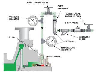
Dual unpressurised seals
Dual unpressurised seals (previously known as tandem seals), defined in API682 as arrangement 2, utilise an unpressurised buffer fluid between two pairs of seal faces. The inner seal faces are lubricated by the process fluid. Any leakage across the inner seal is absorbed by the buffer fluid and dissipated in a controlled manner.
For slurries, this arrangement leads to contamination of the buffer fluid with solids and abrasion of the seal faces. To combat this an API Plan 32 would also be recommended for a dual unpressurised seal, with the same drawbacks as a single seal for added fluid expenditure, but with the additional costs of circulating another fluid.

58 pump industry | Autumn 2020 | Issue 31 www.pumpindustry.com.au
SEALS
Figure 1: An example of gland packing within the stuffing box.
Figure 3: Typical dual pressurised seal pressure arrangement.
Figure 2: A typical API Flush Plan 32.
Pressurised dual seals
Pressurised dual seals (previously known as double seals), defined in API682 as arrangement 3, utilise a barrier fluid pressurised above the process pressure. Any leakage across the inner seal face will therefore be from the barrier fluid into the process fluid. The seal faces are lubricated by the clean barrier fluid.
As the leakage across the inner seal faces is clean barrier fluid, abrasive particles from the slurry are flushed away from the seal faces.
This is the most expensive option due to the complications of providing a pressurised barrier fluid system. However, this option generally offers better reliability than the other two arrangements since seal performance is not dependent on the process fluid for lubrication.

Dynamic lift USP sealing technology
A conventional mechanical seal operates by utilising the higher-pressure fluid as a film between two precision lapped seal faces. The hydrodynamic action of the seal allows a film of usually <1 micrometre to form which lubricates, cools and minimises mechanical contact. This principle ensures that any leakage across the seal faces occurs from a higher-pressure fluid into a lower-pressure region.
Dynamic lift technology uses grooves on one of the seal faces to generate pressure between the seal rings so that they physically separate and operate in non-contacting mode. The most well-known use of this is for dry gas seals, where a barrier gas at a higher pressure than the sealed pressure is used to separate the faces.
Dynamic lift USP utilises specially optimised spiral grooves on one of the seal faces to create a pumping effect. The face design generates a positive pressure across the seal face from inside diameter to outside diameter, i.e. from the lower pressure buffer fluid to the higher pressure process fluid in the seal chamber. This has the effect of raising the pressure of the fluid film between the seal faces to above that of the process. The pumping mechanism creates a controlled flow of buffer fluid from low pressure into the higher-pressure process fluid. The seal acts like a pressurised dual seal without the need to pressurise a barrier fluid. The low-pressure buffer fluid is sealed by a containment seal typically operating at the preset buffer fluid pressure but capable of containing the sealed chamber pressure in the event of an inboard seal failure.

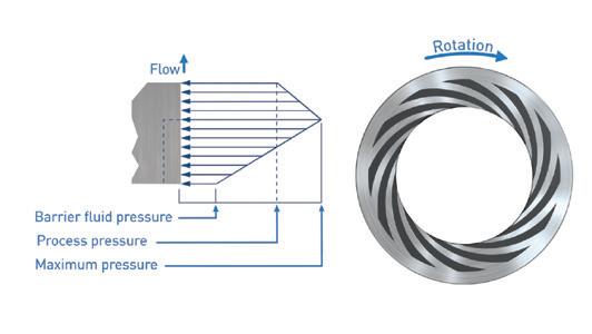
Dynamic lift up-stream pumping technology offers many advantages over the traditional dual seal approach:
1. The technology is ‘non-contacting’ and therefore the usual pressure-velocity limitations imposed by contacting seals, and the resultant wear, do not apply
2. The power consumed is significantly lower than a double or tandem seal arrangement
3. The positive flow of clean buffer fluid into the seal chamber can provide a cleaner sealing environment
4. Compared to a non-pressurised tandem seal, a USP seal has the advantages of clean fluid lubrication and non-contacting operation
5. Compared to a pressurised double seal, a USP seal requires a much simpler support system and reverse pressure is inherently eliminated
6. The process fluid is on the outside diameter of the seal faces – solids suspended in the process fluid are centrifuged away from the seal faces and secondary seal area
7. Buffer fluid leakage to atmosphere is significantly reduced when compared to a pressurised dual seal – where the outboard seal can often operate with a considerable pressure differential
8. The concept allows a simple upgrade of single or multiple seal services where process changes have rendered the process fluid a poor seal lubricant
9. In services where the process pressure is variable, or where pressure spikes are likely, the spiral groove constantly regulates against this varying pressure, maintaining a sealing gap at all times
10. The non-contacting seal faces generate little heat compared to a conventional solution. The seal faces are cooler and therefore much less likely to encourage scale formation
11. In all cases, should sealing integrity of the inboard seal be lost, the outboard seal will safely operate under full duty conditions
12. The flush requirement for double or tandem arrangements is often unnecessary with USP due to low heat generation, reducing water usage
13. Increased mean time between repair (MTBR)
14. Only a simple support system is required with a small footprint
Developing the first high pressure USP seal
The first high pressure USP seal was designed and validated back in 2003, leading to the creation of standard USP product ranges. The initial design focused on an emulsification of oil and water contaminated with varying concentrations of sand.
The 75mm seal design shown in Figure 7 was tested under the following operating conditions:
59 www.pumpindustry.com.au pump industry | Autumn 2020 | Issue 31 SEALS
Figure 4: Typical double seal pressure arrangement.
Figure 6: USP pressure generation.
Figure 5: Typical up-stream pumping pressure arrangement.
Shaft speed: 3600 rev/min
Seal chamber pressure: 5 to 40 bar(g)
Seal chamber temperature: 70-80°C
Process fluid: Water, water/oil/sand (20% wt. sand)
Buffer fluid: Seawater
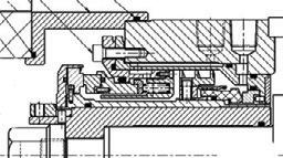
Figure 8 shows the condition of the seal face components following a 200 hour slurry test. After testing faces were in asnew condition with no wear or contact marking.
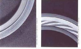
Since this application went live, further development has been performed with designs capable of running at up to 100 bar(g), with laboratory testing performed in excess of 200 bar(g). Finite Element Analysis and Computational Fluid Dynamics aid with optimisation of seal face parameters. This allows the design of bespoke engineered solutions when applications fall outside of the standard USP range of products.
Simplified seal support systems
By nature of the design and operation of dynamic lift USP mechanical seals, the required support system complexity is greatly reduced compared to that used with a conventional pressurised dual seal.
Due to a lack of cooling requirement for many designs, the system requirement is simply an elevated tank with an optional automatic fluid top up system. Figures 9 and 10 show the basic support system.
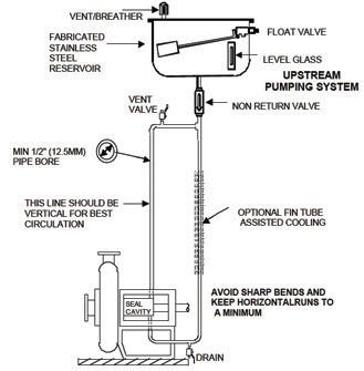

Case study
Background
Industry: Mining
Site: Mine raw material processing plant
End Product: Kaolin used in pulp and paper, deinking, paints and coatings, adhesives, caulks and sealants
Customer need
• In 2009, a processing plant serving a kaolin mineral mine experienced downtime related to an unreliable pumping process
• When the magnetic process to remove ferrous metal particulate from the kaolin mixture was interrupted, production came to a standstill, cutting into profits
• A pump with braided gland packing could not stand up to the fluid flow volume
• The process plant wanted to move quickly to improve the pump and seal’s costly three-to-six-week mean time between repair (MTBR) track record
• The mine’s parent company, one of the world’s leading mineral producers, looked to its local distributor and John Crane for a solution to the costly maintenance pump application
Application
• The local John Crane Distributor identified the faulty standard seal and packing that were damaged due to vibration and intermittent pump volume flow caused by continuous periodic cavitation
• MTBR for the seal was three to six weeks, each event impeding the process flow throughput volume, ultimately reducing end product flow and output
• The distributor, who also supplied seals for the original project, requested input from John Crane after attending a training session that reviewed the USP’s non-contact technology
• The mine chose a unique and innovative face design to improve the MTBR – dynamic lift USP available only from John Crane
• The non-contacting technology would be less affected by pump flow interruptions and vibration
Solution
• The kaolin mine replaced the existing seal and braided packing with John Crane’s series 5620 series standard double seal, fitted with inboard and outboard pumper mating rings, creating the unique design geometry of the high-pressure USP seal
• The flush line was filtered to >5 microns with an inline filter, deadheaded to seal and the remaining inlet/outlet ports were plugged
60 pump industry | Autumn 2020 | Issue 31 www.pumpindustry.com.au
SEALS
Figure 7: First high pressure USP arrangement.
Figure 10: In-situ typical piping plan arrangement.
Figure 8: Seal faces post slurry testing.
Figure 9: Schematic showing typical piping plan arrangement.

• The low-volume, high-pressure USP seal works by propelling a small amount of buffer liquid along the path normally sealed by a mechanical seal face and into the higher-pressure product side
• The 5620 USP seal design greatly reduces seal and equipment wear, utilising a face spiral groove pattern to direct barrier fluid toward the outside diameter, setting up a sealed gap and eliminating physical contact of the faces during operation
• The John Crane 5620 USP seal gave the mill the solution to withstand the intermittent flow and vibration
Summary
Dynamic lift USP sealing technology has been available to the marketplace in various shapes or forms for many years, however it is only in the last ten or 20 years that the technology has been available to allow these designs to operate in more demanding environments. The technology is an alternative to traditional gland packing or standard mechanical seal arrangements.
As industries are being encouraged to reduce energy and water consumption, improved sealing technology is seen as one method to improve environmental performance. Due to non-contacting operation, dynamic lift USP sealing technology can assist with lowering overall environmental impact through reduced energy and water consumption, whilst the relative simplicity of the design and operation allows a significant improvement in not only the reliability, but the operating costs of the associated assets. As user confidence levels continue to develop, dynamic lift USP technology is being applied more frequently to increasingly demanding applications.


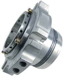

www.pumpindustry.com.au SEALS
SCENIC PRECISE ELEMENT INC. No.5, Sin-Jhan Rd., Chian-Jhen District, Kaohsiung City 80672,Taiwan Tel : +886-7-8111359 Fax : +886-7-8221033 Email : scenic@scenic-seals.com · service@scenic-seals.com ww w. sce ni c-sea ls.com Youpumpup.Wesealup! CarLife®99SSTM Flushless Single Cartridge Seal For Slurry Application CarLife®99TM General Purpose Single Cartridge Seal LD388TM Dual Cartridge Seal for VOC Emission Prevention Over 30 years of fluid sealing experience. Mechanical seal for DIN, ANSI, JIS, and API-682
Powering HVAC with heat pumps
By Luisa Romeo, Journalist, Pump Industry magazine
With the CSIRO estimating that 40-60 per cent of household energy consumption is used for air conditioning and water heating, and the costs of power rising, the installation of geothermal systems for residential and commercial heating, ventilation and air conditioning systems (HVAC) has become popular as an energy efficient, environmentally friendly and reliable alternative to conventional systems in Australia. Here, we look at how geothermal compares to conventional HVAC, the equipment involved and how it works.
Geothermal systems have been used in applications for many decades in North America and Europe as highly efficient and reliable sources of heating and cooling, helping to reduce dependence on fossil fuels. While it has yet to receive the same level of popularity in Australia, it is starting to gain more traction for single dwelling, small commercial applications and pool heating, and is being installed as part of a major residential development – the largest system of its kind in the southern hemisphere.
Geothermal vs conventional HVAC
The key difference between geothermal and HVAC systems is that geothermal systems use the ground as a heat source in winter and as a heat sink in summer. On the other hand, normal air conditioning systems have a condenser sitting outside the home, which has a coil that refrigerant runs through and a fan sitting behind the coil to disperse air across it. This means in summer it uses the outside air to reject heat from the condenser coil, and in winter it uses outside air to collect heat.
The main benefit of this set-up for geothermal systems is that the temperature below ground is constantly 22-23 degrees, so less energy is required to provide heating or cooling, whereas air temperatures vary on a seasonal – and daily – basis, affecting the efficiency of conventional systems.
However, because geothermal requires coils to be placed below ground, installation costs more than conventional HVAC as more work and equipment is required during construction. Generally, this additional cost will be recouped quickly due to geothermal’s energy efficiency and low operating costs – and therefore decreased utility bills.
Another difference between geothermal and conventional HVAC is the design and amenity of the equipment.
Geothermal systems are generally much smaller than normal air conditioning condensers, so they don’t have the same noise and airflow issues associated with conventional systems. This becomes more beneficial as housing lots get smaller or when there is no backyard as these systems are much quieter than air conditioning condensers and free up room if there is an attached outdoor space.
How does geothermal HVAC work?
Geothermal HVAC systems use a ground source heat pump to move a refrigerant through underground coils.
In cooling mode, the heat pump circulates a hot refrigerant gas through the geothermal loops in the ground so that it can absorb the cooler temperatures found below the earth before
becoming a liquid. It then gets sent to the heat pump where the pressure is lowered so it cools further before it is circulated through the fan coil unit in the home to absorb the heat in the air and cool the house.
In heating mode, a cool refrigerant is circulated through the geothermal loops to absorb the heat from the ground. It is then compressed and circulated through the fan coil unit to provide heating.
In both modes, after the refrigerant has re-heated (cooling mode) or cooled (heating mode), the cycle repeats itself.
How the system provides cooling and heating
1. The heat pump uses a compressor to compress a refrigerant gas
2. Thermal energy is rejected to the ground via hot (or cold) refrigerant
3. The hot (or cold) refrigerant is circulated through a fan coil unit in the home providing ducted heating or cooling
4. Waste heat can be captured for use in heating domestic hot water
The future of geothermal HVAC in Australia
The Australian Renewable Energy Agency (ARENA) has provided $500,000 in funding to Climate-KIC Australia to lead a three-year longitudinal study, monitoring 40 homes in a new residential precinct, to see what the benefits of geothermal are for the residential sector and greenfield estates.
Climate-KIC is leading the project team comprising University of Technology Sydney (UTS), Curtin University, Wattwatchers and the Green Building Council of Australia, with $180,000 each of funding as well as in-kind support over three years from the NSW Office of Environment and Heritage, and Frasers Property Australia.
The study, which began in 2019, will look at not only energy efficiency, but also comfort levels, indoor air quality and a range of other factors that are important for residential homes.
If successful, the project will pave the way by establishing a business case for industry-wide adoption of ground source heat pumps within local, renewable and efficient energy systems.
62 pump industry | Autumn 2020 | Issue 31 www.pumpindustry.com.au
HVAC AND BUILDING SERVICES
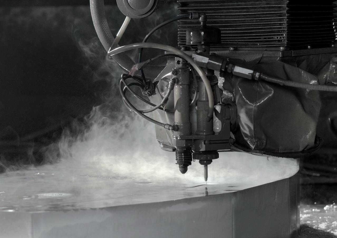

Reducing material cost through waterjet technology



PLASTICS WEAR PLATE RUBBER GASKETS
Waterjet technology
Waterjet cutting is a process of precision cutting that utilises high pressure water.
We can process a wide array of materials. Heavy gauge plate, thin sheet stock and composite materials (i.e. carbon fibre, phenolics etc.).
It is not uncommon for 6+ inch aluminium and titanium to be cut on waterjets to near final shapes. Edge quality of the parts can vary depending on customer requirements.
We can process anything from a very rough cut for hog-outs, to a very fine edge for precision, finished parts:
Cut up to 6 m x 3 m (20 ft x 10 ft)
Thickness up to 254 mm (10 in)
Improved yield and less waste material
Supplied close to net shape reducing customer machine time
Shorter lead times
Zero heat effected zone
Processing of customer supplied materials
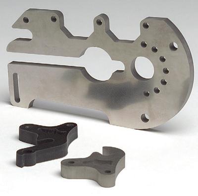
Contac t th yssenk ru pp Mater ials Austr ali a Pt y Lt d Unit 2, 7−10 Denoci Cl os e We th erill Pa rk , NS W 2164, Austr ali a T: +61 2 9757 7777 F: +61 2 9757 7700 sales.tk mater ials.au@ th yssenk ru pp.c om www.t hyssen kr up p- mater ials -a us tr alia.co m Materials Services

VISUALISING A PIPING SYSTEM
By Ray Hardee, P. E., Engineered Software
All my Pump Industry articles focus on the total system and how the equipment works together to meet the system requirements. E-mails from readers and many of the questions asked during my Piping System Fundamentals Seminars ask for clarification of how to use this information to gain a better understanding for designing and building new systems or operating and maintaining existing systems. As a result, I decided I would provide an overview to new readers, along with a review to long time Pump Industry readers.
Introduction of pumped systems
Pumped systems can be classified as either process systems in which a product is made, or support systems in which a service is supplied to make a product.
Figure 1 shows a process system where a fluid is pumped to make an intermediate product used later in the facility. In this example, a process fluid is pumped from a supply tank, through a process component such as a heater or filter, and a control loop to maintain the level in the process tank. Systems like this are typically found in refineries and chemical plants.

Now we will look at a typical service system providing cooling water to various loads in multiple process systems (see Figure 2). In this example, cold water is pumped from the cooling tower basin through two parallel heat exchangers to reduce the process fluid temperatures in two different streams. The flow rate through each path or circuit is adjusted to maintain the process temperature to the set value. The hot water is then sent to the cooling tower where the excess heat is removed by evaporation. The cold fluid then is recirculated.
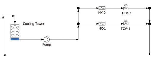
64 pump industry | Autumn 2020 | Issue 31 www.pumpindustry.com.au TECHNICAL
Figure 1: A process system in which the fluid passes through the system to make an intermediate product.
Figure 2: A support system in which a fluid is recirculated in the system to provide cooling water to various facility process loads.


ITT Goulds Pumps make the widest range of pumps in the industry with pumps to handle virtually any service.
Optimum reliability and performance in all industries including:
- Chemical
- Pulp and Paper
- Mining and Minerals
- Power Generation
- Oil and Gas
- Primary Metals
- Water and Wastewater
- Food and Beverage
With our extensive range of pumps, first class customer service and ongoing comprehensive support, Kelair Pumps are second to none when it comes to your pumping needs.
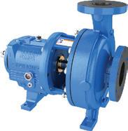

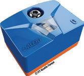
65 www.pumpindustry.com.au pump industry | Autumn 2020 | Issue 31 TECHNICAL 3196 i-FRAME® ANSI Process Pump 3185 i-ALERT® Process Pump i-ALERT® Monitoring System WHEN PUMP KNOWLEDGE MATTERS Rely on Kelair Find out more today 1300 789 466 www.kelairpumps.com.au 03/20
An ITT Brand
Consider GOULDS PUMPS for all your industrial process pumping needs.
Elements of a piping system
In looking at these two examples we see similar equipment, but each example is very different. Further, these examples are very small, but they can quickly become more complex in actual operating facilities. At first glance it may seem difficult to understand how the equipment operates as a total system, but when we look at each item in the system and identify its function, we can start to make sense of the system and its interconnections.
All equipment found in a piping system falls into three basic elements: pump elements, process elements and control elements. The elements must work together so the system can meet its design requirements. Let’s start out by looking at each element individually.
• The pump elements include the pump, the drive adding energy to the pump, along with the pump seals, and other support systems for the pump and drive
• The process elements include the supply and destination tanks, the interconnecting pipelines, the process equipment, and the cooling tower
• The control elements consist of the plant instrumentation to measure a process variable, the controllers to match the set value to the measured value, and the final control element to match the output to the set value
All piping systems regardless of their design, size or complexity are made of these three basic elements working together to meet the systems design objectives.
Function of each element
Now let’s discuss the function of each system element.
The pump elements supply the fluid energy to the system required by the process or the service. We will demonstrate using a motor driven pump. The electrical energy to the motor stator is converted to mechanical energy by the motor’s rotor. The motor’s rotor connected to the pump shaft and impeller converts the mechanical energy to fluid kinetic energy. The pump's fluid energy is then used to move the fluid through the system.
The process elements make the product or provide the services to meet the system design requirements. The process elements consist of tanks and vessels making up the system boundary, the pipelines to transport the process fluid through the system, and the process equipment to meet the system objectives. For example, the purpose of the system presented in Figure 1 is to heat the process fluid before going to the process tank where it will be used in other process systems.
INCREASED EFFICIENCY SMART CONVEYING TECHNOLOGY


Smart Conveying Technology (SCT) provides quick maintenance, significantly reduced life cycle costs and the shortest downtime. Smart Seal Housing, the newest innovation for SCT pumps, removes the need to dismantle the suction or discharge pipework for inspection and replacement of the mechanical seal.
Adjustable stator restores pump efficiency
Reduced maintenance time by up to 85%
Increased energy savings compared to conventional progressive cavity pumps
Easy retrofit onto your existing SEEPEX pumps
Up to 200% longer stator life
Rapid removal and reassembly of mechanical seal
66 pump industry | Autumn 2020 | Issue 31 www.pumpindustry.com.au
TECHNICAL
Smart
Smart Seal Housing
Smart Rotor Smart Stator
Rotor Technology
SEEPEX Australia Pty. Ltd. T +61 2 43554500 info.au@seepex.com www.seepex.com
The function of the control elements is to improve the quality of the product or services. The control elements consist of the instrumentation, control loop and final control elements to heat the fluid to the optimal temperature for the process. If the control elements do not maintain the fluid temperature to the optimal value the process will not operate efficiently. It is important to remember that the energy added in the heat exchanger is thermal energy and does not affect the hydraulic energy added to the system by the pump.
Considering the usage of energy for moving the fluid in the piping system the energy supplied by the pump is consumed by the process elements and the control elements, and it can be reduced to the following formula:

Formula 1: A process system in which the fluid passes through the system to make an intermediate product.
In Formula 1, the value h is the energy unit for head measured in meters of fluid. Measuring fluid energy in metres is customary when working in pumped systems, as a result all the examples presented in this column will list fluid energy in meters of process fluid.
Conclusion
In this article, we grouped the elements found in all pumped systems and discovered what part each element plays in the total system. We also saw how the energy supplied by the pump is used by the process and control elements to make a product and improve its quality.
In future articles, we will look at the operating characteristics of each element and see how that knowledge can be used to better understand the operation of real-life piping systems.
About the author
Ray T Hardee, PE, is the Chief Engineer and a principle founder of Engineered Software Inc., creators of PIPE-FLO® and PUMP-FLO® software. The PIPE-FLO product line helps some of the largest companies across a variety of industries find hidden profit in the design and operation of their fluid piping systems through simulation software, modeling services, and training opportunities. Hardee is a member of the Hydraulics Institute, ASME Energy Assessment for Pumping Systems standards committee and ISO Pumping System Energy Assessment committee. Ray’s publications include Piping System Fundamentals and contributions to HI’s Pump Life Cycle Cost and Optimizing Piping Systems. He can be reached at SimGuyRay@eng-software.com.


67 www.pumpindustry.com.au pump industry | Autumn 2020 | Issue 31 TECHNICAL
Tel: (03) 9699 7355 www.pressureandsafetysystems.com.au 9479P&SS-PIM We handle Pressure ® Triple OffseT ValVe lOW OperaTiNG TOrQUe HiGH iNTeGriTy sHUT-Off • SUITABLE FOR - LIQUIDS, GASES & STEAM • TEMPERATURE RANGE -60°C TO +427°C • ISO STANDARD ACTUATOR MOUNTING • FULLy LUGGED • BUTT-wELD ENDS • DOUBLE FLANGED SHORT FACTORY LEAD TIMES
Industry Voices
Billie Tan
For Billie Tan, Assistant General Manager at Regent Pumps, working in the pump industry isn’t something she initially considered when finishing her university studies. But after getting a break in the industry in 2009, Billie has become a leader in pumps, projects and production management. Here, she talks about finding her place in the industry, and what can be done to promote more women to consider a career in pumps.

Getting started with pumps
For Billie, the journey into the pump industry was not as straightforward as others.
“I started at BKB Pumps & Tanks in November 2009. I was about a year out of university and was seeking a ‘Project Management’ type role and came across a Project Coordinator role that was open at BKB,” Billie said.
“To be honest, there wasn’t an intention to get into the pump industry or any other industry for that matter.”
However, Billie said she has always been drawn to projects and teamwork, and the opportunity that she discovered in the industry allowed her to follow her passion for management.
“I have always been an individual geared towards working in projects/management and when the opportunity came up, it looked interesting and I gave it a go! It has brought me to where I am today,” Billie said.
Describing herself as a very loyal employee, Ms Tan spent nine years with BKB Pumps before bringing her talents to Australian-owned pump manufacturer Regent Pumps in 2018. She is currently the Assistant General Manager and is responsible for the overall operations of the business and production.
Finding a place in the sector
For Billie, the pump industry has shown that it’s a varied sector, with many different types of people coming together and lots of unique challenges along the way.
“It is challenging, it’s competitive, it’s stressful, and I get to meet and talk to many different types of people within the industry that have different experiences which enables me to learn something new every day,” Billie said.
“You’ve got some that ‘know it all’ and others that surprise and boggle you because of what they don’t know about pumps and systems but work within the pump industry. The spectrum is from one extreme to the other!”
Even without a specific mentor in the industry, Billie said she always had a few individuals that she could go to when she needed advice on something or to assist with a technical question.
Another highlight for Billie so far in her career has been the opportunity to work on a project for the redevelopment of the iconic Melbourne Park.
“Although in the early part of my career and perhaps only a small section of the precinct’s redevelopment, working on this project taught me a lot from a technical perspective, personal
68 pump industry | Autumn 2020 | Issue 31 www.pumpindustry.com.au INDUSTRY VOICES
–
Billie Tan at the PIA AGM in 2019 with Will Shanasey, James Blannin and David Lawrence.

development and management skills. Although it was stressful and there were many roadblocks, it somehow was memorable,” Billie said.
Promoting diversity in the industry
There’s no doubt that the pump industry is a maledominated sector. However, overcoming old stereotypes, confidently backing abilities, and supporting and inspiring the next generation are all ways to help encourage more women to enter the industry, according to Billie.
“There is most definitely still a gap in the industry, or anywhere for that matter, where females in technical roles are viewed to not be capable enough,” Billien said.
“For me personally, I have not had very much that I needed to overcome, but I still do get on occasion ‘are you sure you can assist me?’ or ‘you might want to double check with someone else’.
“However, as long as one is confident, you just need to stand by your view or the information that you have provided, and no one should further question you.”
Another avenue to inspire more women to enter into the industry would be to become more proactive at the university level where students are deciding what direction their careers will go.
Billie said organising more agenda-driven get togethers, organised by women, for women, would help to give insights to prospective engineering students and show them what the pump world is all about.
She also has some valuable words of advice for women who are interested in becoming part of the pump industry.
“Be tough, be persistent, listen, learn from others' experiences and most importantly, understand what you are doing, not just follow what others do.”
Having fun outside of pumps
For Billie, life outside of pumps is full of fun and interesting hobbies. Travelling is a major interest as well as working on home improvement projects and, like many people, she enjoys watching movies and TV shows.

INCREASE PUMP EFFICIENCY WITH VESCONITE WEAR RINGS


69 www.pumpindustry.com.au pump industry | Autumn 2020 | Issue 31 INDUSTRY VOICES
Billie Tan, Assistant General Manager at Regent Pumps.
Robert Egginton W: +61 3 9796 4098 M: +61 413 596 517 robert@vesco.com.au www.vesconite.com C M Y CM MY CY CMY K

The pump industry relies on expertise from a large and varied range of specialists, from experts in particular pump types to those with an intimate understanding of pump reliability, and from researchers who delve into the particulars of pump curves to experts in pump efficiency. To draw upon the wealth of expert knowledge the Australian pump industry has to offer, Pump Industry has established a panel of experts to answer all your pumping questions.
This edition of Ask an Expert will look at the wide range of benefits offered by using customised progressive cavity pumps for wastewater and sludge treatment applications.
Q: Can progressive cavity (PC) pumps handle sludge with variable dry solids content?
A: Yes, they can efficiently handle a wide variety of sludge applications with differing dry solids content because of their stable flow rates, minimal pulsation, excellent suction lift and high self-priming capabilities. They also accurately meter flocculants to aid thickening and integrate easily with control systems to maximise productivity.
PC pump manufacturers focus on offering solutions that not only operate effectively, but also ultimately save you costs.
• Energy efficient pumps: lower energy requirements
• Ease of maintenance: pumps designed with quicker and easier access to the drive side and rotor side components without needing to dismantle the pipework
• Extended pump life: high-quality parts, predictive maintenance and pump monitoring options, reduced wear on components
• Flexibility: installation and pump design customised to your application

A modern dewatered sludge handling pump with easy maintenance access – in this case the SEEPEX BTVE range.
Q: One of the industry’s major concerns is reducing energy costs. Do PC pumps offer any special solutions?
A: PC pumps already reduce operating costs because of their efficient operation, but on top of that, several PC pump manufacturers have designed pumps specifically focused on energy-efficient performance. These newer technologies mean reduced maintenance time, extended service life and significantly reduced lifecycle costs.
70 pump industry | Autumn 2020 | Issue 31 www.pumpindustry.com.au ASK AN EXPERT
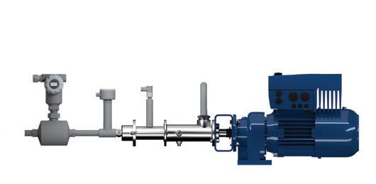
Q: Can PC pumps be incorporated into pumping systems?
A: Yes. They can work within various customer systems or be supplied as a complete solution directly from the manufacturer. There are many diverse connection options: control systems, higher-level automation systems, digital monitoring/analysing systems or with macerating, dosing and/ or chopping pumps (2-in-1 system).

From primary and thickened sludge transfer to chemical dosing, progressive cavity pumps provide the best pumping solution designed specifically for your application.
Peter Vila, Managing Director of SEEPEX Australia, is a progressive cavity pump expert. He has been involved with pumps for over 40 years. Peter spent the first five years repairing pumps and the following 35 years in technical sales, 20 of which have been with SEEPEX progressive cavity pumps.
For more information on progressive cavity pumps, please contact SEEPEX Australia on (02) 4355 4500 or at info.au@seepex.com


71 www.pumpindustry.com.au pump industry | Autumn 2020 | Issue 31 ASK AN EXPERT
One example of modern PC technology – in this case the SEEPEX SCT pump.
A modern PC pump system – in this case showing SEEPEX’s Smart Dosing Pump.
Efficient operations of pump systems (Part 3)
The PIA’s Australian Pump Technical Handbook is a cornerstone text for the Australian pump industry and, in our opinion, a must have for anyone who deals with pumps on a regular basis. In this ongoing series, we feature abridged chapters from the classic book to showcase the various areas covered and to reacquaint readers with the technical aspects of pumps. In this issue, we look at what elements make up a pump system that impact on energy consumption.
Pump system elements
A pumping system can have three main elements which can each be individually reviewed and an assessment made on the impact of losses on energy consumption.
• Pump suction line - this element covers the pipe from the liquid source to the pump suction connection. The liquid source can be above or below the pump centreline
• Pump discharge line - this elements stares at the pump discharge connection and runs to the liquid discharge point(s). Losses in pipes, fittings and other equipment in the discharge line such as filters, heat exchangers, etc.
• Control systems - the pumpset requires some sort of control, even if it is only a basic manual start/stop system. The control system can contribute to how efficiently the overall system operates
Pump suction line
When designing an efficient pump suction line, the first consideration is that the Net Positive Suction Head (NPSHA) from the system is greater than the Net Positive Suction Head Required (NPSHR) for the pump.
NPSH is the total head at the pump suction branch over and above the vapour pressure of the liquid being pumped.
NPSHR is a function of the pump design and is the lowest value of NPSH at which the pump can be guaranteed to operate without significant cavitation. There is no absolute criterion for determining what the minimum NPSH should be, but pump manufacturers normally select an arbitrary drop in total dynamic head (differential head) of three per cent as the normal value for determining NPSHR.
In designing a pump suction line the following factors should be taken into account:
• The static suction head - the vertical distance between the liquid and the centreline of the pump suction flange
» Where possible, the pump should be arranged to operate with positive suction head
» Where this is not possible, the pump should be position with the minimum height differential between the free surface of the suction reservoir and the pump suction flange
• The friction losses in the suction line should be minimised. This applies to both pipes and fittings. The friction losses in
pumping systems are proportional to the square of the fluid velocity and the length of the overall piping system. The following guidelines should be followed:
» The suction line should be as short and straight as possible to minimise friction loss
» The suction line should be at least the same size as the pump suction connection. If it is larger, an eccentric reducer should be fitted to the pump suction connection
» In sizing the pump suction line, the speed of the liquid through the pipe should be 1-2m/sec unless the fluid contains solids in suspension valves in the suction line should be limited to a pump isolating valve in the suction line, and a foot valve and strainer for a non self-priming pump with a suction lift
» When a pump is working with a suction head, it is sometimes necessary to fit an inline strainer to protect the pump. If a strainer is fitted, it should be selected to minimise the loss across the strainer and have a differential pressure gauge to allow operators to know when the strainer needs to be cleaned
» The pipe from the liquid source to the pump suction should slope up to the pump when pumping from below the pump and slope down to the pump when pumping from above the pump to eliminate the possibility for air to accumulate in the line
» If the pump is drawing from a pressurised source on the suction tank at high elevation to the pump, care should be taken to ensure that the pump can accept the high suction pressure, as this can, in some cases, pace loads on the pump bearings and seals which could increase maintenance requirements and/or lead to possible early failure of these parts
» When selecting isolating valves, foot valves, strainers, bends etc., it is recommended to choose those items that will provide minimal friction resistance
» Intake design should be carefully considered
Pump discharge line
The majority of the total head that a pump generates normally comes from the discharge line in the form of static head, friction losses and leakage etc. Static head is normally determined by site conditions, and friction losses are determined by the type and sizing of the pipe, pipe fittings and other components.
72 pump industry | Autumn 2020 | Issue 31 www.pumpindustry.com.au
PUMP HANDBOOK
Pipes
There are several factors that should be considered when selecting a discharge pipe:
Fluid Properties
• Temperature
• Chemical properties (pH)
• Viscosity
• Solids content
Pipe Considerations
• Pressure rating
• Overall pipe length
• Surface roughness
Furthermore, the maximum design flow usually determines the size of the pipe, while the maximum system pressure would be a factor in determining the pipe material along with the other fluid properties.
When designing a pump discharge line, the following additional factors should be taken into account:
• Reference to pipe material data should be made to select appropriate performance criteria. For example, oil at 300°C should not be pumped through plastic pipes.
• Pumping high viscosity fluids substantially increases the friction loss in pipes, which may require the use of larger diameter pipes and longer radius bends
• To maximise the overall efficiency of a pumping system, it is often necessary to size the discharge piping in a way that balances energy consumption with pipe capital cost
• For process plants, where a pipe run is short, the pipe can be sized based on a fluid velocity in the pipe of 2.5-3m/sec. For longer pipeline, such as water supply lines, where friction usually becomes a large part of the total head a pipe can be sized based on fluid velocity on the pipe of 2m/sec
Valves
When considering valves, it is important to understand why the valve is installed and what function it needs to fulfill.
For example, it is generally recommended that a centrifugal pump is fitted with an isolating valve and a non-return valve. The isolating valve will assist with pump maintenance and removal, and the non-return valve prevents backflow and reverse rotation which can damage a pump and/or driver. A flow valve may be fitted in the discharge system to allow the pump operator to vary the flow rate to meet operational demands.
The requirements for valves in a discharge pipeline are determined by process considerations; the correct design is based on experience. It is normally recommended that selection should be done in consultation with a valve supplier.
Pipe fittings and branch connections
Pipe fittings are generally selected from standardised components that are available.
These allow for changes in the direction of the flow system connecting the suction reservoir to the discharge reservoir along a chosen path. These include elbows, long radius bends, T and Y branches, and other forms of fittings. While the frictional loss in these fittings is a factor, rapid changes in direction can cause rotation and turbulence in the fluid, which can have detrimental effects and increase friction losses.
Pipe diameter change
Not all sections of a piping system will need to accommodate the full discharge flow rate from the pump.
Many systems distribute the overall flow to different locations. Typical examples are a water reticulation system, an irrigation sprinkler system or a fire protection sprinkler system. Sudden changes in diameter should be avoided as these increase friction losses and consume additional energy. A change of diameter should be effected gradually by using a taper piece. For best results , the included angle of a taper piece should be 10-13 degrees.
Miscellaneous discharge pipe components
Discharge pipes often have components in the line which are required by the process in which the pumping system operates. All components such as flow and pressure regulation devices or valves will absorb energy and increase the friction losses. While this is the function for the process designer, these need to be viewed in conjunction with the envisaged flow control system for the installation as this will have an impact on the total system efficiency.
Final discharge outlets
All pumping systems must terminate somewhere.
• Nozzles - these are designed to project the fluid by means of changing pressure energy into velocity energy. Losses in the nozzle itself should be minimised by good design
• Open outlets - these can be used to deliver the fluid to a dam, reservoir, sump or tank, and is at atmospheric pressure. An outlet is normally the same size as the pipe from the pump which allows the fluid to be discharged with minimal exit losses. A flap is often fitted to prevent anything entering the pipe system when the pump is not operational.
• Closed outlets, come in several forms:
a. An outlet that is at the bottom of a vessel filled with fluid and open to atmosphere
b. An outlet with a float valve can be used in simple tank filling operations. This leaves the system pressurised unless the pump is switched off. More recently, options such as float switches or level sensors can be used to switch off the pump when the tank is full
c. A pressurised outlet is one in which a system is pumping into a vessel that is under pressure such as a boiler vessel. It has the same properties as (a) above, except the pressure normally imposed is much higher than the static head in the tank
Pump control systems
The performance of a pumping system can be controlled in a number of ways depending on the user requirements from the installed plant and pumping equipment:
• By mechanically controlling the system output by utilising throttle valves, pressure reducing valves or by-pass valves
• Selecting the appropriate size and number of pumps operating in the system to meet varying operating conditions (series and parallel operation)
• Using pump speed control to vary the flow and head generated by the pumping equipment. This can be achieved by mechanical methods to vary the speed of a pump (i.e. vee-belts, gearboxes, variable speed couplings or similar). Alternatively, by electrically controlling the driver either to alter the pump speed or start/stop the system to meet its varying demands
Further information and detailed diagrams, equations and schematics can be found in the Australian Pump Technical Handbook, available from the PIA website. In the next edition of Pump Industry, we continue to explore energy efficiency in pumping systems, looking at pump-system match, and drivers and controls.
73 www.pumpindustry.com.au pump industry | Autumn 2020 | Issue 31 PUMP HANDBOOK
PUMP SCHOOL
Impeller trimming – noise changes (Part 3)
Following on from Impeller trimming Part 1 and 2, this article will continue to outline things that can happen when the impeller vane diameter is reduced. In Part 3, we will look at noise changes that can occur with impeller trimming.
Noise changes
When writing a pump specification, many practicing engineers limit the impeller diameter to 85 per cent of its maximum diameter. Such a limitation is actually a misunderstanding of a design concept known as quiet pump operation. This misunderstanding may force the selection of a larger pump for the application. The idea here is not that the impeller diameter should be 85 per cent of the maximum published diameter, but 85 per cent of cutwater diameter (0.85 cutwater ratio). To fully understand the quiet pump operation design concept refer to Figure 1.
In designing a pump casing, a design engineer first determines the volute scroll (A) necessary to handle the desired volume of water. This volute scroll terminates at the volute cutwater (B) at the base of the discharge nozzle (C). The volute scroll is drawn around a base circle (D), which is sufficiently large enough to allow insertion of the impeller. The distance from the shaft centerline to the volute cutwater is called the cutwater radius and twice this distance is the cutwater diameter.
Hydraulic noise becomes a factor when the periphery of the impeller passes too close to the cutwater. When designing a pump, the distance between the impeller and the cutwater is a compromise between pump efficiency and pump noise. Typically, cutwater ratios (D/F) of 0.9 and above produce higher noise, and cutwater ratios of 0.8 and below produce significantly lower pump noise. Cutwater ratio of 0.85 is commonly specified by practicing engineers, thereby realising a minimum reduction in efficiency with a mean reduction in noise level.
From the above, it may be understood that a specification should more properly read "impeller diameter not to exceed 85 per cent of the volute cutwater diameter”, rather than "impeller diameter shall not exceed 85 per cent of the maximum impeller diameter capable of being installed in the pump casing".
Specifying the later statement is safer since the impeller diameter would be even smaller than the desired maximum.
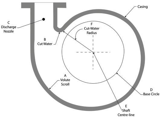


74 pump industry | Autumn 2020 | Issue 31 www.pumpindustry.com.au Article courtesy of Kelair Pumps Australia “When Pump Knowledge Matters” Phone: 1300 789 466 or visit www.kelairpumps.com.au
Figure 1


schedule
76 pump industry | Autumn 2020 | Issue 31 www.pumpindustry.com.au ADVERTISERS’ INDEX Adelaide Control Engineering ................... 9 AllightSykes OBC, 22 Angus Flexible Pipelines 7 ARBS Exhibition ........................................ IBC ASM PUMPS 29 AW Austworld ............................................... 21 AWMA Water Control Solutions IFC Brown Brothers Engineers 12, 49 BÜrkert Fluid Control Systems ................ 41 Caprari Pumps Australia 57 CNH Industrial ............................................. 35 Crusader Hose 19 Deutz Australia 1 Drive Systems .............................................. 23 Dwyer Instruments 71 Ebara Pumps Australia ............................... 17 ETM Pacific 20 Franklin Electric 31 IPD Industrial Products ............................. 51 ITT Blakers 20 Kelair Pumps Australia.............................. 65 Lk Diesel Service 43 Pressure And Safety Systems 67 Rexnord Australia .........................................11 Roto Pumps 75 Scenic Precision Element ......................... 61 Seamech 3 SEEPEX Australia 66 TECO Australia ............................................ 55 Thyssenkrupp Materials Australia 63 United Pumps Australia............................. 13 VescoPlastics 69 WEG Australia 45 Welling & Crossley ....................................... 15 Editorial
Subscribe NOW www.pumpindustry.com.au/subscribe/ WINTER 2020 Deadline: 22 May 2020 MAIN FEATURE Also featuring DISTRIBUTION Mining Irrigation Oil and gas Food Instrumentation and monitoring WIOA Bendigo - TBC Queensland Mining Expo 2020 - TBC Irrigation Australia/ICID International CongressTBC SPRING 2020 Deadline: 21 August 2020 MAIN FEATURE Also featuring DISTRIBUTION Energy efficiency Smart pumps Couplings Waste Expo Australia WA Mining Conference and Expo Plus the 2021 Industry Capability Guide SUMMER 2021 Deadline: 27 November 2020 MAIN FEATURE Also featuring DISTRIBUTION Wastewater State of the Industry Survey Valves Fire Power generation WIOA NSW AUTUMN 2021 Deadline: TBC MAIN FEATURE Also featuring DISTRIBUTION Water Seals Motors, drives and engines HVAC WIOA QLD OzWater


New dates and information coming soon! ARBS.COM.AU POSTPONED
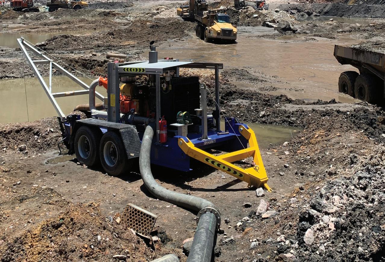
allightsykes.com Call 1800 ALLIGHT


 Patrick Handley, CEO, Waterscapes Australia


