pumpindustry
Top reasons for SEAL FAILURE and how to avoid them
Redeveloping Reef HQ Aquarium’s plant infrastructure

Top reasons for SEAL FAILURE and how to avoid them

Redeveloping Reef HQ Aquarium’s plant infrastructure
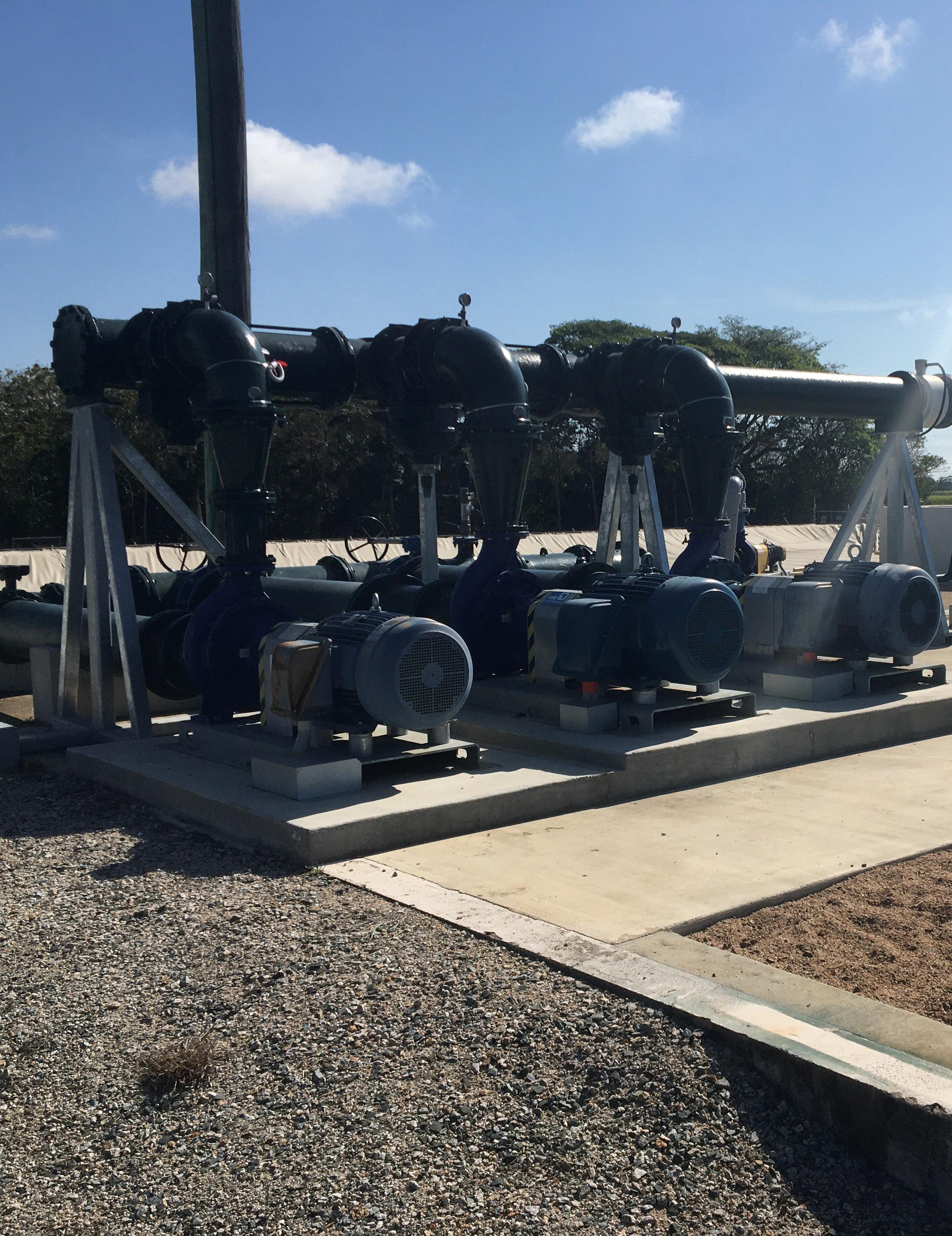
REVITALISE HINCHINBROOK WATER TREATMENT PLANT
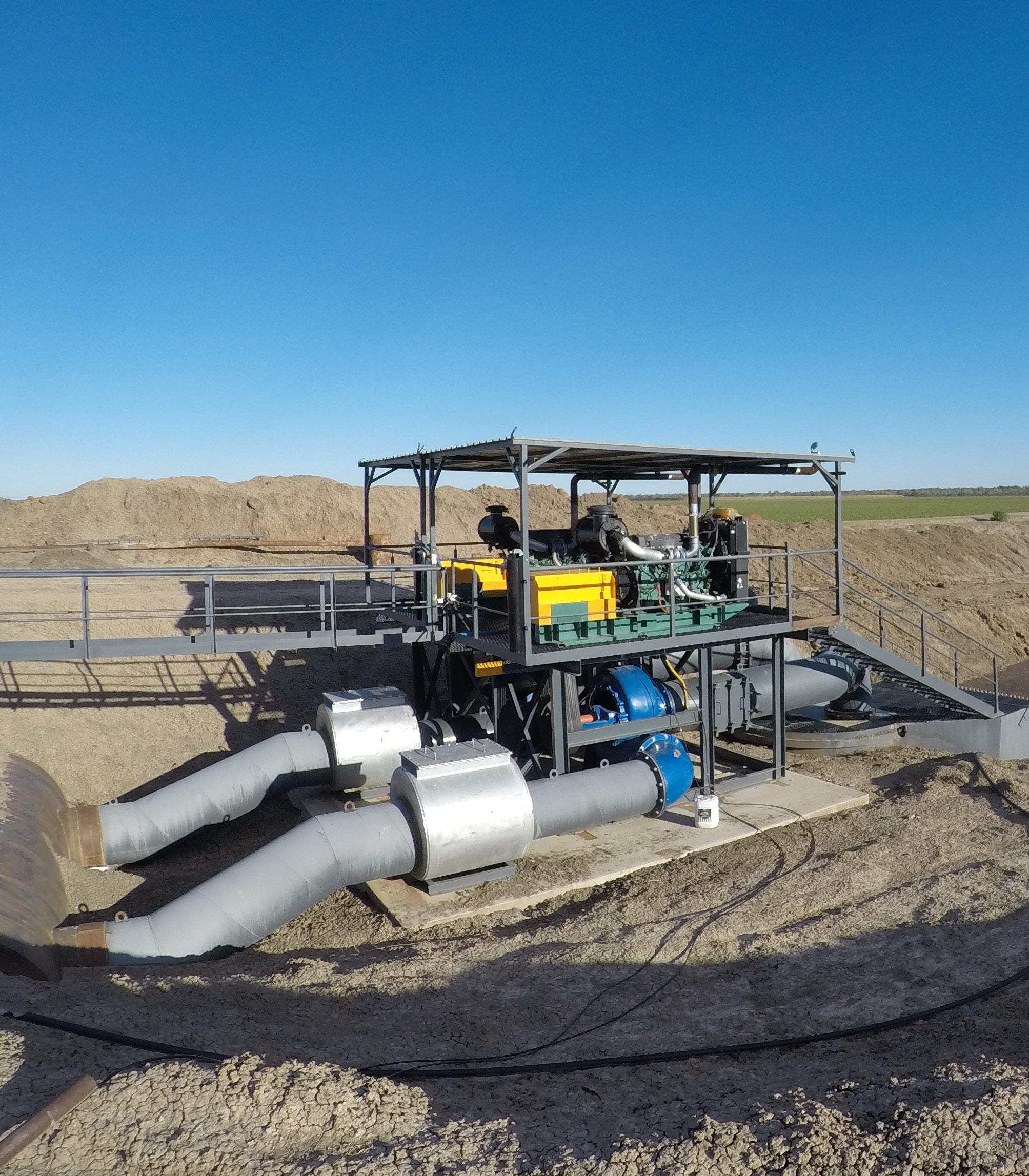
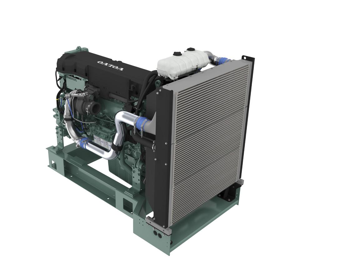
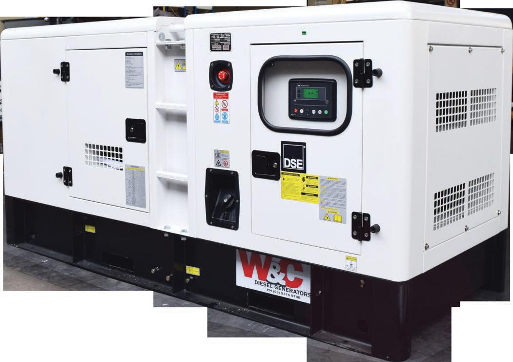
Volvo Penta. Robust, fuel efficient industrial diesel engines that keep running even in the toughest conditions. Easy to install, operate and maintain. A powerful partnership you can trust all the way from the drawing board throughout the operational life of your engine. Competitively priced complete power-pack units ready for delivery Australia wide with a local support team on hand 24/7. To find your nearest dealer visit www.volvopenta.com


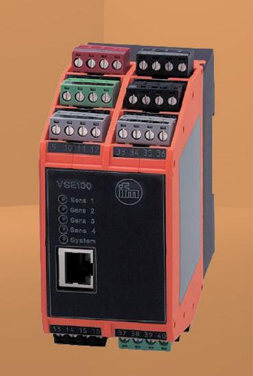

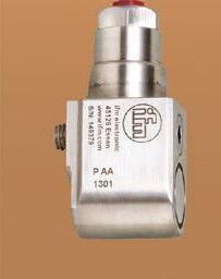


Sense and Process

With this solution the following issues can be detected:
■ Ragging
■ Blockage by foreign objects
■ Faulty or damaged bearings
■ Faulty or damaged seals
■ Wear issues and rub issues
■ Imbalance
■ Cavitation
■ Looseness


■ Unusually high signatures in grinders and macerators


■ Excess Current
■ Sewage Level and Control
■ Flow and Temperature


Submersible pumps do the essential – but dirty work – of transporting sewage to treatment plants. Prone to blockages, ragging, and general wear and tear, pumps need to be monitored to avoid events such as overflow and environmental contamination of public and residential areas.
Optionally, the system can also monitor:
Direct Comms to PLC via front end dedicated ports is also available for:
■ Ethernet Ip
■ Modbus TCP/IP
■ Ethercat
■ Profinet



Hello all and welcome to the Autumn Edition of Pump Industry magazine. Much has happened since the last edition, as the world has changed significantly in more ways than one in recent months. I look at 2020 as being the year of the pandemic, 2021 the year of the variants and 2022 as the year where the welfare of many businesses is severely challenged as we see a continued wave of companies being liquidated, particularly in construction, as cost increases, supply chain issues and availability of staff exact a growing toll. Fortunately our industry, whilst certainly not immune, is better positioned to “weather the storm”.
with the Electrical Equipment Safety Scheme (EESS). For electrical safety, in-scope electrical equipment cannot be sold unless the item is marked with the RCM in compliance with AS/NZS 4417.1 & 2 and the EESS. Suppliers must be registered with the EESS Registration Database.
Pump Industry Australia Incorporated C/-340, Stuarts Point Road
Yarrahapinni NSW 2441 Australia Ph/Fax: (02) 6569 0160 pumpsaustralia@bigpond.com www.pumps.org.au
PIA Executive Council 2022
John Inkster – President Brown Brothers Engineers
James Blannin – Vice President Stevco Pumps & Seals
Kevin Wilson – Treasurer/Secretary Executive Officer
Alan Rowan – Councillor Executive Officer – Publications and Training, Life Member
Ken Kugler Executive Officer – Standards, Life Member
Michael Woolley – Councillor Tsurumi Australia
Geoff Harvey – Councillor Irrigation Australia Limited
Billie Tan – Councillor Regent Pumps
Steve Bosner – Councillor Pioneer Pumps
Joel Neideck – Councillor TDA Pumps
Mat Arnett – Councillor Ebara Pumps Australia
Jamie Oliver – Councillor Grundfos Pumps
And as if this wasn’t enough to contend with, an unprecedented weather event over a ten day period in February/March saw eastern Australia hit by unrelenting rain and flooding that affected approx. 1,000km of the Eastern Seaboard stretching from South East QLD to Southern NSW, causing destruction in its path and sadly the loss of 22 lives, followed by the massive clean up and thousands of insurance claims.
By contrast, parts of Australia are still suffering drought and low rainfall as La Nina and climate change create weather extremes. Sydney has recorded the wettest start to a year ever. The BOM has said that the Warragamba Dam was spilling the equivalent of Sydney Harbour each day; that is 500GL a day.
In terms of rare events, we already know several records were broken. Looking at the 676mm of rain that fell in Brisbane in 72 hours, statistically it is only expected to occur once every 200 to 500 years.
As the masks and social distancing regime of the last two years is gradually disappearing, PIA is hopeful of having more face-to-face meetings and in fact has received offers to host them; but in the meantime we are still planning more online seminars, the first of which was a seminar on Pump Performance Monitoring presented by Malcolm Robertson of Robertson Technology in March.
After the success of Rob Welke’s seminar on Energy Efficiency of Pipelines in November it is planned to have Rob run another seminar on Flow metering for on-site Pump Tests.
We are also trying to find a spokesperson to conduct a seminar on he Regulatory Compliance Mark (RCM), the scope of which has caused some confusion in the marketplace. The RCM is a trademark owned by the electrical regulator that represents compliance
In March, I received a call from a Senior Adviser in the Plumbing Drainage and Special Projects Division within the Department of Energy and Public Works, advising the Service Trades Council (STC) had acknowledged PIA’s request to have suitably qualified Members undertaking repairs and servicing of pumps installed as part of a plumbing or drainage system, and that our request was under review. Specifically, I was asked about training within the industry, and advised there were a number of private practitioners who offered courses, and that many of the larger companies had their own in-house training and professional development. I advised that IAA was the only training provider who was a recognised Registered Training Organisation (RTO) with a nationallyrecognised certification.
It was acknowledged that the PD Act was tightly regulated but there might be avenues they could investigate to facilitate the experience and capability 0f many of PIA’s Members in service and repair. The next meeting of the STC was scheduled for late March. This is a tentative but positive step in attempting to gain recognition for PIA Members based on their vast experience and knowledge. As more information comes to light, this will be shared with you all.
As I alluded earlier, the world has changed, not just with the challenges of factoring in price increases and the uncertainty of supply chains, but also with the Russian invasion in February of Ukraine, a European democratic country of 45 million people. Whilst Ukraine is a long way from Australia, the television and news media are able to show the terrifying and horrific scenes of a fullscale Russian invasion into our homes. This will have enormous humanitarian consequences for a long time to come. It is appropriate that Western nations, including Australia, have imposed severe sanctions on Russia and its political leaders. We all express our sympathy for the Ukrainian people; this is a very challenging time for them and we all hope that a cease fire has been reached by the time you read this editorial.
As always, I wish you all a COVID-safe, flu safe and prosperous year.
John Inkster - President
ABN: 36 426 734 954

C/- The Commons, 36-38 Gipps St, Collingwood VIC 3066 P: (03) 9988 4950 F: (03) 8456 6720 monkeymedia.com.au info@monkeymedia.com.au pumpindustry.com.au magazine@pumpindustry.com.au
Editor: Lauren Cella
Journalists: Annabelle Powell, Christopher Allan, Lauren DeLorenzo, Mikayla Bridge
Business Development Managers: Rima Munafo, Jacob Trad
Design Manager: Alejandro Molano
Designers: Luke Martin, Danielle Harris, Jacqueline Buckmaster
Marketing Manager: Radhika Sud
Digital Marketing Assistants: Andie James, James Holgate
Publisher: Chris Bland
Managing Editor: Laura Harvey
ISSN: 2201-0270




$34 million of sewer upgrades for Melbourne’s northern suburbs are now complete, with project outcomes including a new high-flow pump station and almost 10km of new sewer pipes.
Yarra Valley Water undertook the Doreen to Diamond Creek Sewerage Project over two years, investing in a robust sewer network for a growth corridor in Melbourne’s north.
The project involved building almost 10km of new sewer pipe under parks and roads, as well as supporting infrastructure like a new high -low pump station.
Yarra Valley Water’s General Manager Growth Futures, Chris Brace, said the project, which ran around the busy Yan Yean and Ironbark roads, would service properties in the rapidly expanding Mernda and Doreen areas.
“It will ensure the reliability of the sewerage system and reduce the likelihood of sewage spilling into the environment during heavy rain,” Mr Brace said.
“We’ve worked with our delivery partners, MFJ Constructions and Jaydo, to deliver the project, which is among the top ten projects we’ve committed to complete for our customers.”
Mr Brace said special care had been taken throughout construction to save trees and avoid disrupting areas of cultural sensitivity, including a large stone tool artefact identified near the Plenty River.
This included the use of trenchless drilling technology to reduce excavation, protect more vegetation, and minimise disruption to the community.
“Design partner Jacobs also salvaged almost 400 artefacts at the start of construction and we worked in partnership with the Wurundjeri Woi Wurrung Cultural Heritage Corporation to sensitively repatriate them,” Mr Brace said.
“Our approach to this project is a great example of our commitment to care for customers, the community and environment while providing vital sewerage infrastructure where it’s needed.”
The team also adapted to COVID-19 restrictions to ensure the project was delivered on-time and under budget.
The project included resurfacing of Murray Road to reduce dust, as well as construction of a 2km shared-use path, to improve public access in the Plenty Gorge parklands.
The 24,500ML Tamar Irrigation Scheme has reached a new milestone, with the launch of the Preferred Option Design, which includes five pump stations and 240km of pipeline.
The $288 million scheme covers an area of 89,000ha, and will support agricultural diversity and new jobs in the Tamar Valley.
This design centres on harvesting water sustainably from the Trevallyn Dam and delivering this high-surety irrigation water via 240km of pipeline and five pump stations to landowners located on the East Tamar in areas like Lilydale, Hillwood, Pipers River and Pipers Brooks, and on the West Tamar at Rowella, Beaconsfield, Legana and Westwood.
Once operational in 2025-26, it is forecast that the Tamar Irrigation Scheme will create more than 600 direct and indirect jobs.
Additional on-farm investment is already being planned, with some farmers planning to double the area planted to berries and expand operations across the dairy, fruit, vineyard, livestock and cropping sectors in the region.
This project is one of the many Tranche Three irrigation schemes being developed by Tasmanian Irrigation that play a vital role in assisting the Tasmanian Government reach its target of increasing the farm gate value of the state’s agricultural sector to $10 billion a year by 2050.
The Tasmanian Government continues to work with the Federal
Government and local farming communities to deliver irrigation projects across the state, rolling out Tranche Three projects including: the Don, Northern Midlands, Sassafras Wesley Vale and the estimated $370 million South East scheme.
The South East scheme will be the biggest irrigation project in Tasmania’s history, expected to deliver more than 40,000ML annually, supporting a further estimated $150 million in on-farm investment, with the potential to create more than 2,000 local jobs.
The Tasmanian Government is also progressing the development of a business case for an estimated $300 million Southern Midlands Irrigation scheme, which will deliver a similar economic benefit to the heart of Tasmania.

Standards Australia has shown its support for international efforts to pressure Russia to withdraw from Ukraine, encouraging ISO and IEC to take stronger action.
Standards Australia considers the invasion of Ukraine by the Russian Federation to be unprovoked, unjust and illegal. Russia’s war on Ukraine is exacting a catastrophic humanitarian toll and many organisations have suspended activities in Russia to show support.
In a statement to stakeholders, Head of International, Karen Batt, said that Standards Australia strongly supports Ukraine’s sovereignty and global calls upon Russia to cease its attacks on Ukraine.
Ms Batt believes that ISO and IEC should take a stronger position condemning the violence and supporting global efforts to pressure Russia to cease its invasion of Ukraine.
Regarding the situation, ISO and IEC have shared in communications that:
• The IEC has suspended technical committee activities where Russia is leading the work
• ISO has postponed any meetings of Technical Committees under the leadership of Russian ISO members
• ISO and IEC have also highlighted that they are international organisations that provide an open and neutral platform for collaboration on technical matters which results in consensus-driven solutions Standards Australia has made both organisations aware of its views on the conflict.
In any case, and until such time any other provisions are put in place by ISO and IEC, Standards Australia will support its stakeholders in continuing to contribute to international standards development that supports the multilateral rules-based international

order. Equally, it respects the decisions of any contributors who choose not to participate in technical committee activities involving Russian institutions. Standards Australia recommends that stakeholders contact their Mirror Committee Project Manager or Standards Australia’s international team (intsect@standards.org.au) if they would like to discuss in more detail. VERTICAL TURBINE PUMPS
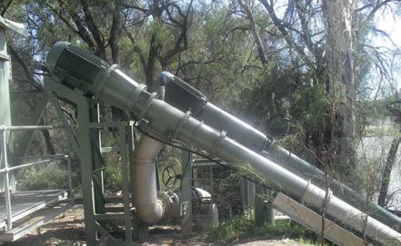
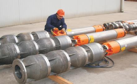
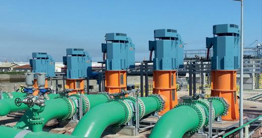
Layne Bowler vertical turbine pumps have a proven record under the most demanding and toughest of conditions.
• Flows to 7,500 L/Sec
• Heads to 500 m
• Power to 1000+ kW
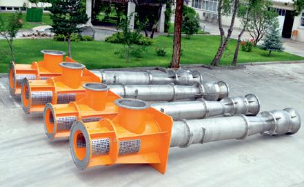
• Temperatures to 150°C
• Bowls Diameter up to 45 inch
WELCOME TO THE
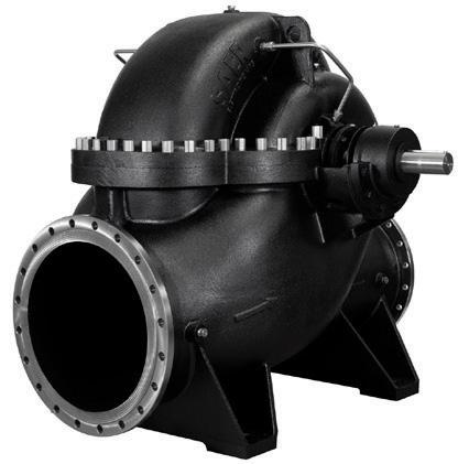
When high head and high flows are required look no further than this quality Italian made range.
• Flows to 5000m³/h
• Head to 220m
• Pumps that exceed EN733 (DIN 24255 standard)


New geotechnical drilling and ground investigations are underway at Borumba Dam near Imbil, Queensland, to help determine its suitability for a landmark clean energy project.
The findings of the ground investigations this year will help determine if a proposed pumped hydro energy storage project could help power two million Queensland homes.
Pumped hydro stores energy by using two reservoirs at different elevations, circulating and reusing the same water.
Its ability to store significant amounts of energy would allow more renewable solar and wind power to enter the market in Queensland.
For pumped hydro at Borumba, a new dam would be required upstream of the existing Borumba Dam to create the upper reservoir and be filled from future rain events.
Headrace and tailrace tunnels, and an underground power station would link the two dams to enable water to be pumped from the lower reservoir to the upper reservoir, and for water released from the upper reservoir to drive turbines to generate renewable electricity.
Queensland Minister for Energy, Renewables and Hydrogen, Mick de Brenni, said the Queensland Government and Powerlink were collaborating to undertake the necessary site research.
“Pumped hydro at Borumba could deliver more clean energy to Queensland, and support 2,000 jobs during construction,” Mr de Brenni said.
“Borumba’s existing dam infrastructure and location in the electricity network shows its potential to support development of more renewables in the Southern Queensland Renewable Energy Zones.
“But there is more work to be done to ensure high levels of environmental protections, and community consultation will play a critical role to ensure that.
“We’re investing $22 million into this, so the process will be thorough and well-considered.
“Over the coming months, our investigations will include detailed hydrological modelling, design of environmental protections, local community and economic opportunities, engineering design and financial modelling.
“This early geotechnical work involves small-scale drilling to investigate geological aspects of the area as part of those wider studies.”
Geotechnical drilling and testing will primarily focus on three main areas around Borumba Dam, including the proposed location of any new dam wall, upper reservoir and underground power station.







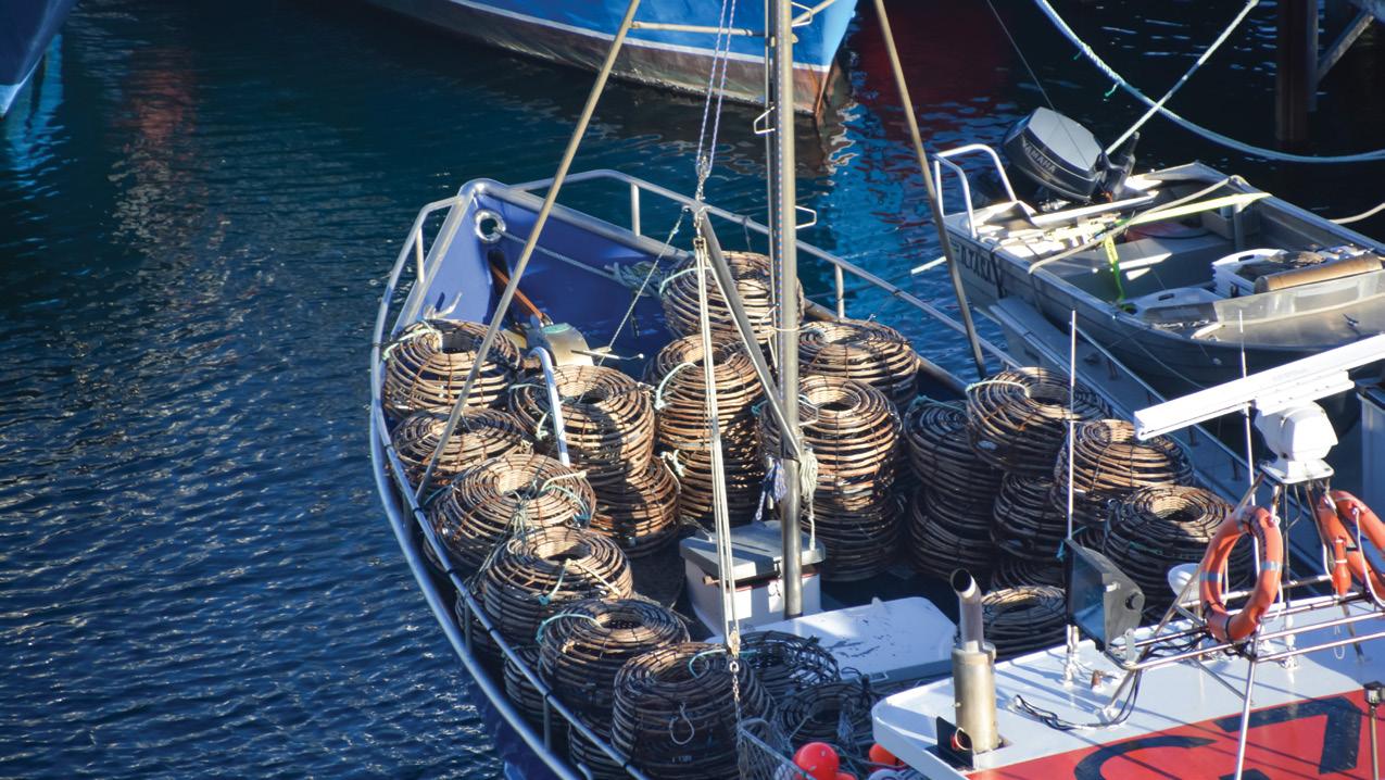
The Federal and Tasmanian Governments are partnering to deliver a $18 million Shellfish Lease Water Quality Improvement Program, upgrading 84 sewerage pump stations across the state.
Tasmanian Assistant Minister for Forestry and Fisheries and Senator for Tasmania, Jonno Duniam, said the funding would upgrade TasWater infrastructure, automation, monitoring and control systems for pump stations, close to the shellfish lease areas, across the state.
The project is made possible through the Federal Government’s National Water Grid Fund, with four projects in Tasmania receiving a grant of $5 million each, including the Shellfish Lease Water Quality Improvement Program.
Tasmanian Minister for Primary Industries and Water, Guy Barnett, said the upgrades will improve TasWater’s facilities while reducing spills and protecting the local oyster farms, the community and jobs in regional Tasmania.
“Tasmania’s $30 million shellfish industry is spread across more than 100 shellfish farms, providing around 300 jobs,
however, a key threat to the industry is sewage spills from TasWater facilities due to rain events or asset failure which can close leases for 21 days.’’
The Federal and Tasmanian Governments state that these upgrades are vital and will provide national-standard infrastructure for future generations.
“Tasmania produces some of the best shellfish in the world, and it is important that we continue to protect local oyster farms and the community from spills,” Mr Duniam said.
“This project will improve TasWater’s facilities in order to reduce spills, delivering better outcomes for both producers and the environment.
“This is a great example of the Commonwealth and Tasmanian Governments working together to deliver for our shellfish operators, and I look forward to working with the Tasmanian Government further in this area.”
The National Water Grid Fund has supported $52.1 million in new and upgraded infrastructure in Tasmania, which will create 53 jobs during construction and 70 ongoing jobs.


Anew recycled water scheme will strengthen water security for Wamuran farmers, providing year-round supply for one of the country’s fastest growing regions.
Unitywater is building the Wamuran Irrigation Scheme (WIS), which will take Class A recycled wastewater from the Caboolture South Sewage Treatment Plant (STP) to a number of farms for irrigation.
This project ensures a sustainable future for the growing regional population and reduces the nutrient discharge into the Caboolture River.
In Stage 1 alone, eleven tonnes of nitrogen and 1.8 tonnes of phosphorus will be diverted away from the river.
Unitywater Chairman, Michael Arnett, said the pipeline was an important investment to support population growth in the region and reinforced Unitywater’s approach to sustainable development.
“This is an exciting opportunity for Unitywater and the community, and we’re proud to be contributing to the sustainability of this region,” Mr Arnett said.
“Higher wastewater volumes due to the increasing population in the Moreton Bay region was the catalyst for the scheme.
“In its first stage, it will deliver about 2.6GL of recycled water per year to a number of farms in the region that were selected to demonstrate the feasibility of the scheme.
“That’s the equivalent of 1,051 olympic swimming pools.”
Mr Arnett said the scheme was being built by the Wamuran Irrigation Scheme Joint Venture – made up of contractor Pensar and two local growers, Twin View Turf and Pinata Farms.
The joint venture was awarded the design and construction contract in October 2019, following an openmarket tender process.
“The design has now been completed and Unitywater is thrilled that this exciting project is coming to fruition,” Mr Arnett said.
Pensar Managing Director, Karl Yunker, said the project provided local growers with climate-independent irrigation, while reducing demand on dams and creeks, and diverting discharge into local river systems.
In turn, the scheme provides Unitywater with an efficient solution for water reuse and sustainable irrigation.
“We formed a joint venture with two of the main irrigators in the region so we could tailor a solution with the end user in mind – making sure that what we’re proposing, designing and delivering meets the needs of growers, and ultimately, Unitywater,” Mr Yunker said.
Moreton Bay Regional Council Mayor, Peter Flannery, said Council was excited to have the innovative environmental project in the region.
“Moreton Bay is the third largest council in the country, and we have one of the fastest growth rates in Australia,” Mr Flannery said.
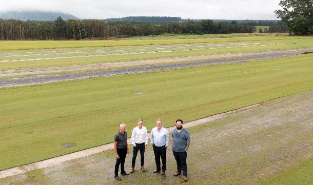
“This project helps address our expanding population and aligns with our environmental initiatives.
“It will create more jobs in the agricultural and downstream industries, and have positive flow on effects for the local community.”
Pinata Farms Managing Director and third generation business owner, Gavin Scurr, said the scheme would significantly benefit the region.
“The Wamuran Irrigation Scheme provides water security, potential for greater crop production, and creates employment within the local region. The whole community benefits,” Mr Scurr said.
Twin View Turf General Manager, Lawrence Stephenson, said the Wamuran Irrigation Scheme was critical for water security in the region.
“It will allow growers to build strong businesses that aren’t vulnerable to changes in weather events and patterns, building a solid foundation for the future,” Mr Stephenson said.
“The region has a number of longterm agribusinesses including avocado, pineapple, berry and turf producers planning sustainable futures that span the next 30 years.
“The Wamuran Irrigation Scheme brings significant confidence to this local industry.”
Construction was anticipated to begin in February 2022, with the scheme expected to be operational in mid-2024.


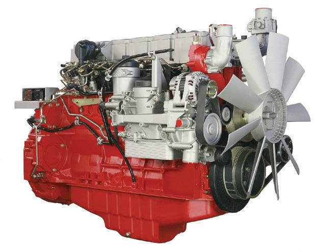

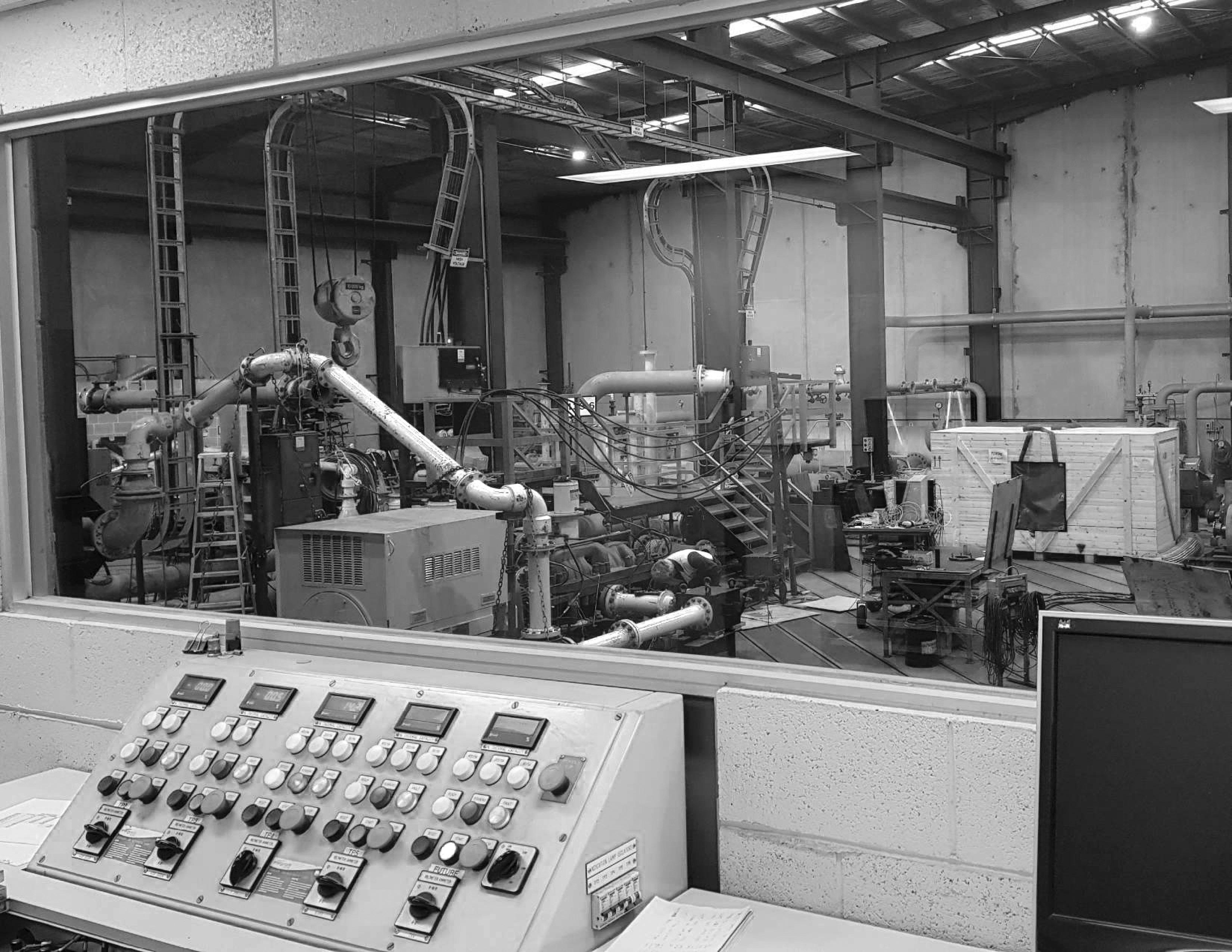
United Pumps designs and manufactures pumps, our extensive Melbourne testing facility is utilized for product development, new pump test and customer pump testing. 2.5Mw capacity with NPSHr capability.
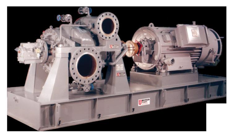
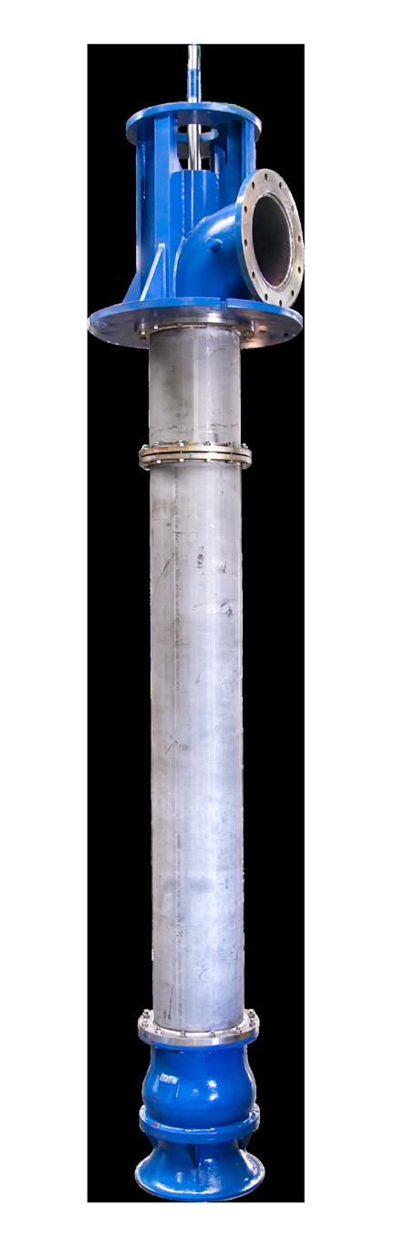
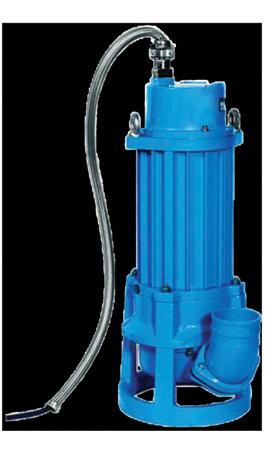
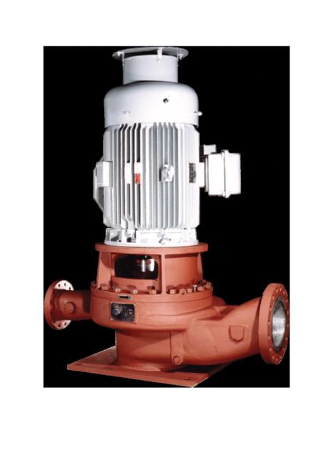

United have made a commitment to API610 pump manufacture in Australia. With decades of experience, we can provide you with the finest engineered equipment and support
Our extensive range of process and water pumps are available in materials to suit your application. With all design and manufacture carried out in Australia we can offer a true Sovereign solution.
Proven track record in municipal water applications over a wide range of the highest quality pumping equipment. Horizontal Split Case, Vertical Turbine, End Suction and Sewage.


EnergyAustralia has commenced construction of Tallawarra B, Australia’s first net zero emissions hydrogen and gas capable power plant, that’s due to be completed by the summer of 2023/24.
Tallawarra B will be located on the shores of Lake Illawarra at EnergyAustralia’s existing Tallawarra Power Station, near Wollongong.
Tallawarra B is one of several projects the business is developing that contribute to the clean energy transition.
The 316MW power station, being built with the support of the New South Wales Government, will sit alongside the existing Tallawarra A power station on the shores of Lake Illawarra in New South Wales, and pave the way for more renewables to enter the system.
EnergyAustralia’s Chief Operating Officer, Liz Westcott, said the start of construction is great news for the local area.
“It’s an exciting time for the Illawarra, with the construction phase creating about 250 jobs and expected to deliver a boost to the economy in the hundreds of millions,” Ms Westcott said.
“The cranes, backhoes and concrete pumps helping build Tallawarra B are local, and so are the people that operate them.
“And where we can, we’re sourcing the plant’s components from local suppliers. It’s a real win for the region.
“Tallawarra B will be stepping in just as Liddell Power Station retires. It will provide quickly dispatchable power for around 150,000 homes when they need it most.
“The new power station will be a first of its kind in Australia –capable of utilising a mix of green hydrogen and natural gas.
“And the plant’s direct greenhouse gas emissions will be fully offset over its operational life.”
During the current stage of construction, major excavations are taking place ahead of the forming and pouring of the main foundations. In May 2022, the gas turbine will be craned into place on top of the foundation.
Once the plant is up and running, EnergyAustralia will offer to buy 200,000kg of green hydrogen per year from 2025.
“What’s particularly exciting is that we will be conducting engineering studies to see if the amount of green hydrogen can increase,” Ms Westcott said.
“We’ve made a commitment to be net zero (scope one, two and three) by 2050, to be out of coal by 2040, and to reduce our direct emissions by 60 per cent by 2028/29 relative to 2019-20.
“And the construction of Tallawarra B is just one of the ways we’re making our promises a reality,” Ms Westcott said.
Around 50 people are currently working at the construction site, which will increase to 250 towards the end of 2022. Ms Westcott has said that keeping workers and the community safe during the current COVID-19 pandemic is a priority during the works.


Northern Australia Infrastructure Facility (NAIF) is set to invest $255 million in upgrades to common-user infrastructure, including a $95 million loan to Water Corporation for the expansion of the Burrup seawater supply and brine disposal scheme.
The Water Corporation investment will support the proposed $4.3 billion Perdaman Urea Project, which is located 20km north-west of Karratha. The project will convert Western Australian liquefied natural gas into about two million tonnes of urea per year (urea is a widely used form of fertiliser for food production).
The Burrup seawater supply and brine disposal scheme will connect to the Perdaman Urea Plant once built.
The two loans are the first NAIF investments into Western Australian Government entities, and include:
• $160 million to the Pilbara Ports Authority for a new multiuser wharf and facilities at the Port of Dampier
• $95 million to Water Corporation for the expansion of the Burrup seawater supply and brine disposal
Western Australian Water Minister, Dave Kelly, said, “The Western Australian Government has committed to upgrading the common-user infrastructure needed to support the Perdaman Urea Project.”
The NAIF loans build on Western Australian Government support for the project, which has provided $47.6 million for road relocation costs, the detailed design of a new Dampier Cargo Wharf and upgrades to seawater supply infrastructure.
Western Australian Regional Development Minister, Alannah MacTiernan, said that the government has also supported this project because it develops manufacturing capabilities and because of its commitment to working closely with Murujuga Aboriginal Corporation.
It is estimated the Perdaman project will create around 2,500 jobs during construction and 200 operational jobs.
Western Australian State Development, Jobs and Trade Minister, Roger Cook, said, “Recent international supply chain issues have highlighted just how important urea is to industry sectors such as agriculture and transport.
“Western Australia has the potential to supply these sectors with the urea they need.
“As the first new gas manufacturing project in the Pilbara for more than a decade, the Perdaman Urea Project will play a role in helping diversify Western Australia’s economy and create local jobs.”
Any WA Government financial contribution is subject to a number of conditions, including the project reaching financial close and all statutory and regulatory approvals being met.

Kelair Pumps Building & Fire Division is one of the most technically-competent suppliers in Australia. We can provide a complete range of fire sprinkler pumpsets for all applications, fully compliant to technical specificiations.
- Purpose built to individual requirements
- Compact, pre-fabricated, complete packaged solutions
- Fully tested to AS2941/ISO9906 and pre-commissioned
- Turnkey installation saves time and labour costs
- Simple to mobilise and transport
- Routine maintenance packages also available
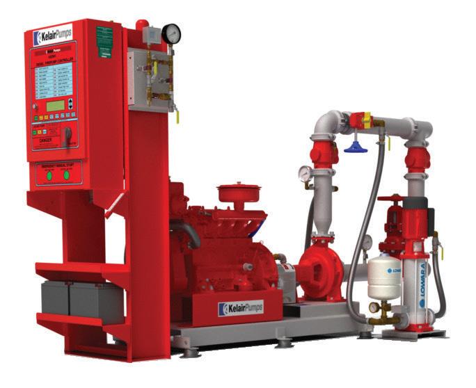
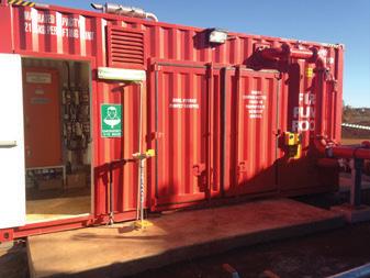
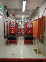
We know the importance of choosing the right equipment to match your process. With our extensive range of pumps, first class customer service and ongoing comprehensive support, Kelair Pumps are second to none when it comes to your pumping requirements.
South Australia is one step closer to delivering its major Northern Water Supply project following a $15 million commitment from both the Australian and South Australian Governments for a business supply case.
Among the options being considered is a desalination plant located in the Upper Spencer Gulf, which would reduce water reliance on the Great Artesian Basin and the River Murray.
If construction proceeds, the project could support up to 8,000 construction jobs and up to 6,000 ongoing jobs once operating.
Deputy Prime Minister, Barnaby Joyce, said delivering a secure and sustainable water source in the region would drive the growth of regional communities and industries.
“Our $5 million investment builds on the state’s $10 million commitment to progress a business case that will inform the future direction of this much-needed project,” Mr Joyce said.
“A safe, reliable and sustainable water source will improve water security, create jobs and help unlock the economic potential of new and expanded opportunities for businesses in the state’s north.
“Since 2015, the Australian Government has committed more than $75 million from the National Water Grid Fund towards projects in South Australia.
“This includes projects supporting premium grape production in McLaren Vale, water security for farmers on the Coolanie Plains, and new water for agribusinesses through the Northern Adelaide Irrigation Scheme.”
Mines in northern South Australia rely on these sources for their groundwater, which can be expensive to extract and can be affected by salinity and other water quality issues.
Previous attempts to provide a sustainable water supply to this vast region have not been successful because they have lacked a strong customer base.
To support the business case, the South Australian Government entered into a Memorandum of Understanding (MOU) with SA Water, BHP and Oz Minerals to progress the projects and address the region’s water needs.
Former South Australian Premier, Steven Marshall, said this was why it has been important for the government to play a coordinating role to bring together a range of potential customers to make this project possible.
He said the Northern Water Supply project has the potential to create thousands of jobs throughout South Australia.
“This project is a once-in-a-lifetime opportunity to secure a brighter future for South Australia and create jobs in an environmentally sustainable way,” Mr Marshall said.
“We are always looking for ways to ensure we are using water efficiently because ongoing and secure access to water is integral to economic growth and regional communities rely on industry for jobs, community strength and resilience.
“A desalination plant is an option we will investigate to provide a sustainable and sufficient water supply to support many industries, including the burgeoning hydrogen industry, mining, horticulture, pastoral, agriculture sectors and the transition to green steel.
“To be able to partner with some of South Australia’s biggest companies to decrease reliance on our finite water resources and future-proof our state in a changing climate is really pleasing.”
Federal Member for Grey, Rowan Ramsey, said the expansion of the resources industry in the north of the state was a reality and not some dream in the far-off future.
“South Australia already relies heavily on the resources industry and water is an essential ingredient to mine, concentrate and process our product,” Mr Ramsey said.
“Currently, this water is sourced from either the Great Artesian Basin or the Murray River, and trying to extract more from these sources is not environmentally sound.
“We are well aware of the long-term issues with the Murray, and the Great Artesian Basin is a national treasure which is vital to our traditional grazing industries and small communities that continue to thrive in our harsh environment.
“While we know the basin replenishes, it is an incredibly slow process and maintaining the pressure in the basin is of paramount importance. Simply, we cannot continue to grow the resources industry without finding a new source of water.
“It is encouraging that our two biggest players in the industry, BHP and OZ Minerals, recognise the need and are part of the MOU.
“Desalination would seem the obvious answer, but there will be a whole lot of community concerns which will need to be addressed along the way. This project will do that.”

Infrastructure Australia has recognised the importance of a new sustainable water source to improve water resilience and increase water supply to the northern parts of South Australia.
Polymaster’s unique Enclosed IBC Bund solves many of the problems associated with IBC storage and chemical/fluid decanting in a weather resistant, purpose-built enclosure.
Æ Full weather protection – stops rain entering the enclosure
Æ Easy forklift loading with wide forklift access from both side and back
Æ 250ltr day tank
Æ Lockable cabinet to keep system secure
Æ Venting by two sides
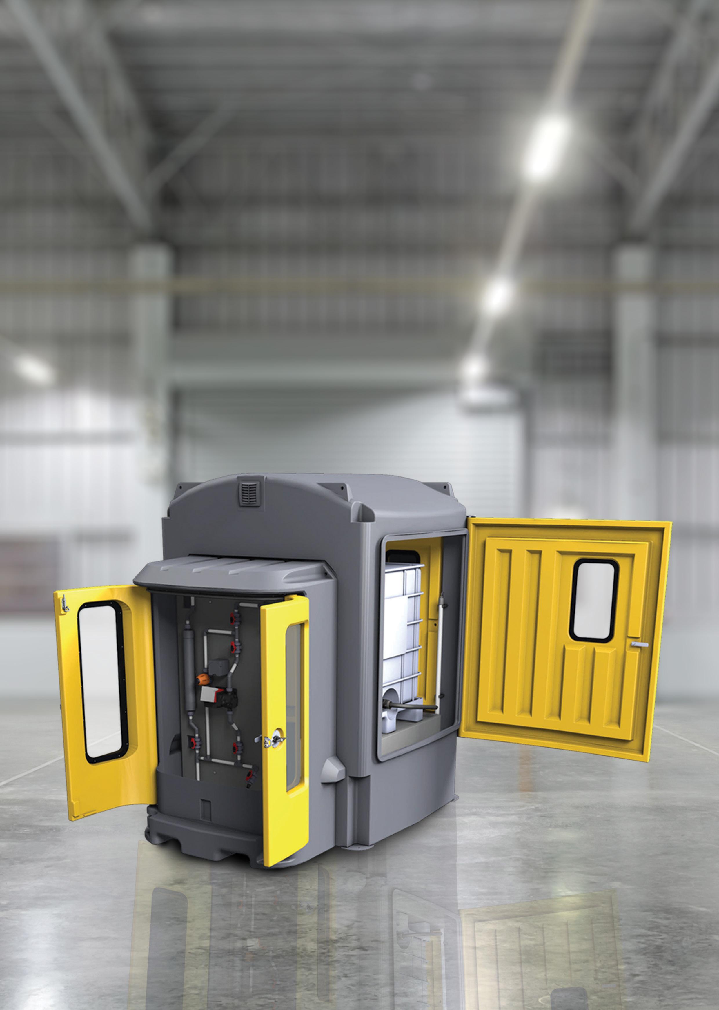
Æ Viewing windows incorporated into the doors
Æ 110% bund capacity complies with AS3780
Æ Sight tube and low-level alarm available
Æ Chemical resistant – high grade polyethylene construction
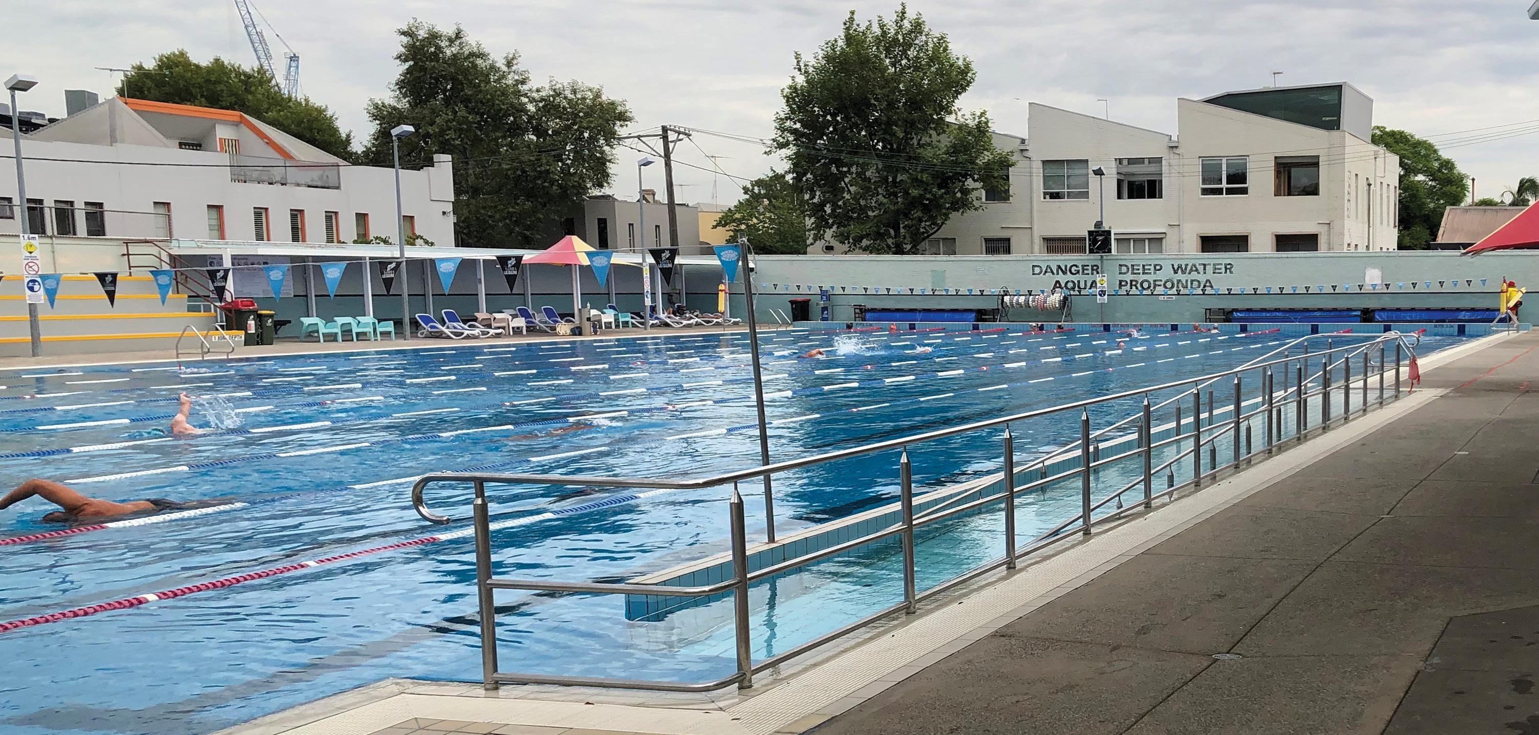
The iconic Fitzroy swimming pool, operated by the Yarra City Council and Yarra Leisure, has recently installed three new Ebara GSD 100-250/11kW close coupled EN733 motor pumps as part of its filtration pump upgrade.
The Ebara GSD motor pump was chosen by mechanical services contractor, Mechanical Plumbing Services (MPS), due to its quality, proven hydraulic design and competitive pricing. The GS/GSD pumps come as standard with a high-quality electro deposition corrosion-resistant coating to the ferrous static components, both internal and external, making them ideally suited to harsh swimming pool environments.
The GS/GSD range is the Ebara Corporation (Japan) new global range of EN733 water pumps and utilises the most advanced hydraulic computer software available. Ebara Engineers in Japan have been able to improve and increase the pump efficiencies of the new GS/GSD range above most other available pumps of similar design and standard on the global market. The majority of the GS/GSD pump range are MEI>0.7 efficiency index with the balance MEI>0.6, an indication of the high-quality design and manufacture by Ebara.
The Ebara GSD range of close coupled motor pumps and the GS range of bare shaft EN733 end suction pumps are both manufactured in component form at Ebara Corporation (Japan)-owned and managed factories in South East Asia.
After being assembled from these components by skilled tradesmen at the Ebara Pumps Australia facility in Melbourne, the pumps are then hydrostatically tested and inspected to our Japanese parent’s strict QA policies and procedures.
The Ebara GS/GSD range of EN733 pumps are a true 16 bar working pressure with a high grade SiC/Carbon/EPDM Burgmann mechanical seal fitted as standard. Galvanised steel baseplates that have been fully engineered by Ebara Japan engineers are also available as an optional extra for the GSD motor pumps.
About Ebara Corporation
Ebara Corporation was founded in Japan in 1912 as a manufacturer of industrial pumps. Today, as a group it consists of more than 70 companies in six continents with a workforce of more than 12,000 and with company-owned and Japanese-managed factories covering nine countries and four continents.
The huge scale of production and distribution is matched by a constant commitment to research, development and design of new products and the modern technologies for the manufacturing of them. Ebara products have gained a worldwide reputation for their technology and quality.
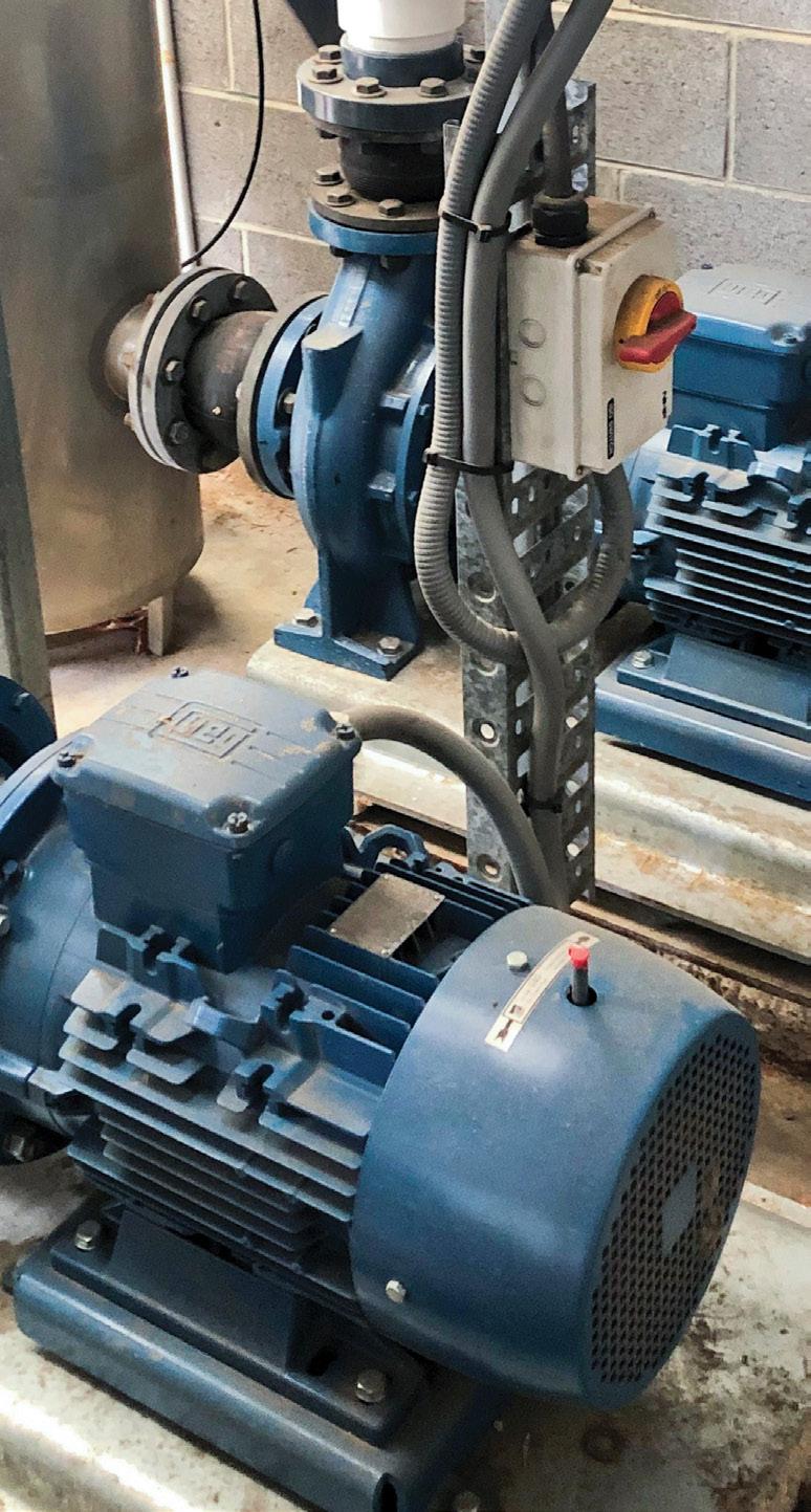
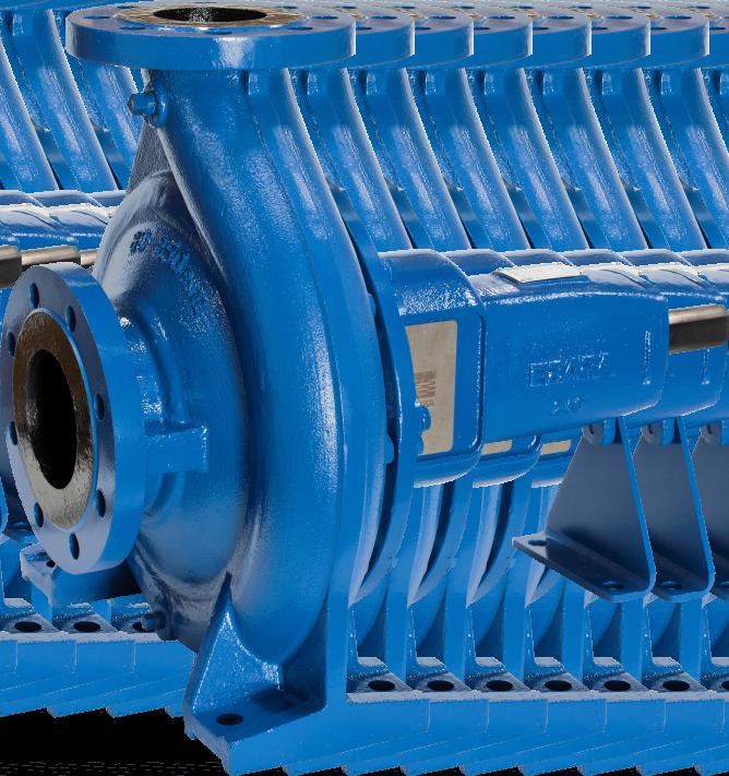
Combining over 100 years of experience with the latest computer aided design, EBARA has developed the new GS series of pumps that offer world leading performance and efficiencies.
Pumps to EN733 dimensions
16 Bar rated. PN16 flanges (24 Bar hydrostatic test pressure)
High efficiencies. MEI ³0.6 (Minimum Efficiency Index)
Mechanical seals to EN12756
Protectors to ISO13852
O’ Ring seal for casing
Cast iron components ED painted (Electro deposition painting)

When we started to think about Esybox Max, we asked ourselves how to manage the evolution of the Esybox range. It was clear from the very beginning, it could not just be something bigger. We felt we had to bring forward the path of evolution, completely changing the rules of the game for booster sets in residential and commercial buildings. Esybox Max is the outcome of listening to and communicating with many different people who will be in direct contact with the product.
Introducing a new concept and industry first in the booster set industry, Esybox Max is an integrated pumping system for pressurisation in commercial building services. Available in two power sizes, it consists of modular elements that allow different configurations to cover the needs of medium/large apartment blocks and high buildings (even over 14 floors). Each unit consists of the single, double or triple connection base and the pumping units – a four-pump system is available with the additional kit to connect two double bases.
Large energy savings are achieved with the DAB inverter combined with a brand new permanent magnet motor. DAB also designed completely new hydraulics, making it leaps ahead in terms of energy efficiency. But it is not just energy efficiency that is at the forefront of this new technology.
Esybox Max will improve the storage efficiency in the warehouse. Where there was once one booster occupying space, you can now fit three twin pump booster sets in its place. This allows people to store the full range on one pallet, meaning a customer can pick up an off-the-shelf booster solution of up to four pumps on the same day. Keeping it flexible, DAB has the on-site assembly concept. So if you have difficulties getting to the pump's location, due to narrow stairways and corridors etc., you can choose to assemble your booster on-site which will only require moving smaller, lighter boxes into the location then carrying out a quick and easy assembly.
DConnect
The Esybox Max also offers full connectivity and control using DAB’s
DConnect technology which is built into the pump and offers many more advantages than typical BMS systems. Performance, data storage and remote monitoring support users, and facility managers can control their pumps from anywhere, making sure that the running parameters of the pumps follow project specifications exactly and avoiding any possible site issues for complete peace of mind.
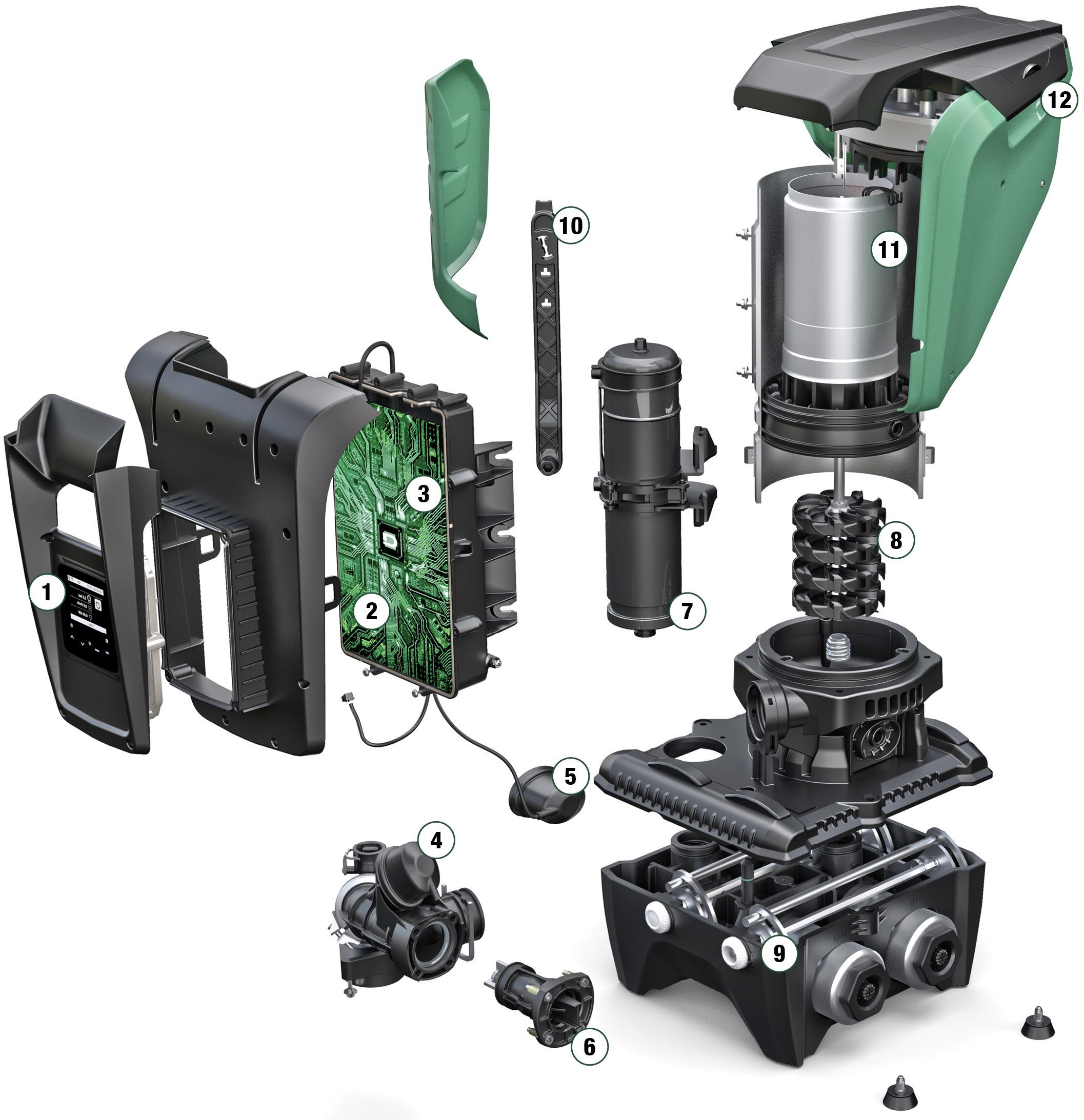
(1) Display (2) Inverter
(3) Module Wifi/Bluetooth
(4) Pressure sensor (delivery side)
(5) Pressure sensor (suction side)
(6) Non-return valve
(7) Two Litre expansion tank
(8) Impellers
(9) Hydraulic connections
(10) Fast connection tool
(11) Water cooled permanent magnet motor
(12) Handles
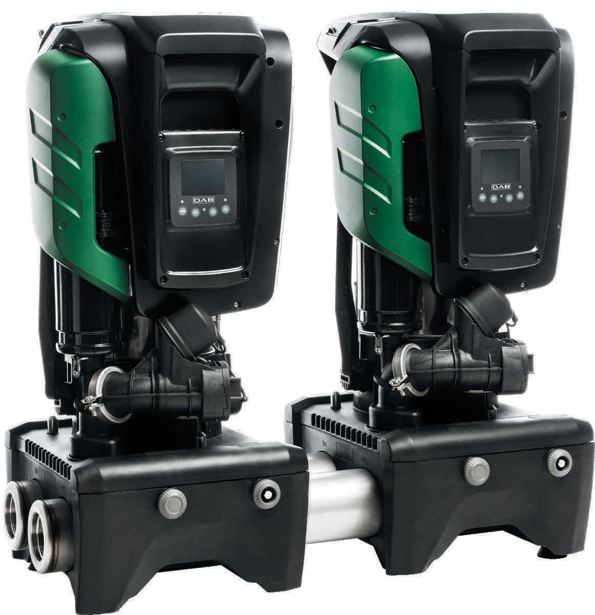
The DAB inverter has been combined with a brand new permanent magnet motor. We also designed completely new hydraulics, making it leaps ahead in terms of energy efficiency.
The most compact and integrated booster set on the market. Connect 1, 2, 3 or 4 Esybox MAX units.
Easy to maintain
Connect and control from anywhere with DConnect.
Easy to move & install
Quick On-Site Assembly.
Affordable web based remote control for your installation
With DConnect you can use your smartphone to connect directly with the pump using the simple interface. All adjustments are possible remotely, allowing total control with no unwanted surprises.

We at Roto Pumps started our journey by supplying our very first pumps to the mining industry. As a user-turned manufacturer, we have always understood the major challenges faced by the mining industry. This led us to carefully design and develop advanced helical rotor pumping technology to meet the challenging demands of the industry.
Roto has provided helical rotor pumps to all types of mines i.e. underground, open surface, placer and in-situ mines for the last 53+ years. In modern times, the major challenges that are faced by mining companies are:
• High wear and tear in elastomeric stators and rotors
• Reduced pump performance due to the use of rechromed rotors
• Low lifecycle of pumps and spares
• Reducing recurring pump, spare and operation costs
• Need for prompt service and support
• Regular requirement of readily available pumps and spares
Since it has been associated with mining from its early days, Roto has evolved and invested in its manufacturing practices to stay ahead of the competition while meeting the global mining industry demands. Roto Pumps has developed a complete range of helical rotor pumps for the mining industry, solving critical media pumping challenges and successfully handling all the major applications in mining and explosive industry such as:
• Cement grout/grout mix
• Clay and mineral slurries
• Coal water mixtures
• Dirty water
• Explosive mix transfer and filling
• High pressure wash
• Gland service
• Mine dewatering
• Mineral processing
• Mortar with fine oily water
• Oily water transfer
• Rock dust slurry
• Water spray for dust suppression
• Gace dewatering and high head dewatering
Built for a long lifecycle
Roto has an advanced manufacturing plant for developing a wide range of
helical rotor pumps and spares. It has six strategic overseas establishments with large assembly and warehouse infrastructures. These establishments are backed by strong localised sales teams to provide readily available pumps and spares, and prompt service support.
Roto has developed a unique rotorstator geometry that ensures low rubbing velocities between rotor and stator; eventually leading to an increased rotor and stator lifecycle. This also helps in providing consistent flow at varying pressures.

Roto’s specially designed two-pin joint (Cardan universal joint) provides flexibility in operating the pump in both directions. These joints are designed to have more angular movement which reduces the overall footprint of the pump; thus making it more compact. Also, these two pin joints can easily withstand loads caused by pumping at high discharge pressures.
Roto ensures strict in-house process control and stringent quality checks for designing and manufacturing of the high-quality energy efficient pumps and spares (including spares for other brands) having a long lifecycle and less operational costs.
Over the years, Roto has mastered the art of providing highly efficient elastomeric stators in a wide range of materials having high dimensional accuracies. These stators remain highly abrasion-resistant for a longer period of life compared to other stators available in the market. This is achieved by continuously focusing on in-house compound formulation and preparation, and mould design and manufacturing of elastomeric stators. We also have an in-house polymer test lab where it runs various tests on stators.
The rotor is the lifeline of helical rotor pumps. In mining, rotors are subjected to very high abrasion; thus most mining companies prefer hard chrome plated metallic rotors for longer life. Over a period, the high abrasion leads to faster wear out of the rotor, thus affecting the life of the pump.
Presently, many mining companies send these worn out rotors to local hard chrome plate companies to remove the chrome, rebuild and re-chrome the rotor. If they fail to ensure the correct dimensional accuracies (on major and minor diameters) between rotor and stator as per the original design, this eventually results in faster wear turnout of both parts, and finally damaging the whole pump and reducing the overall pump lifecycle. So in many cases it is better advised to order a new hard chrome plated rotor knowing it will be to correct dimensional tolerances. Roto can provide rotors in a varied range of materials, including exotic materials, to ensure optimal life of the component.
Mining is one industry Roto knows well and it will continue to strive to develop technically superior products resulting in smooth and reliable pumping operation in order to provide peace of mind to our mining customers.


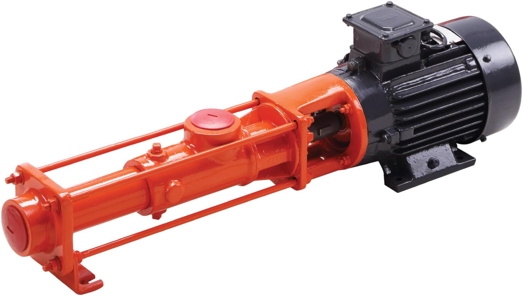
High-performing helical rotor pumps with exceptional suction capabilities for varying pressure applications.




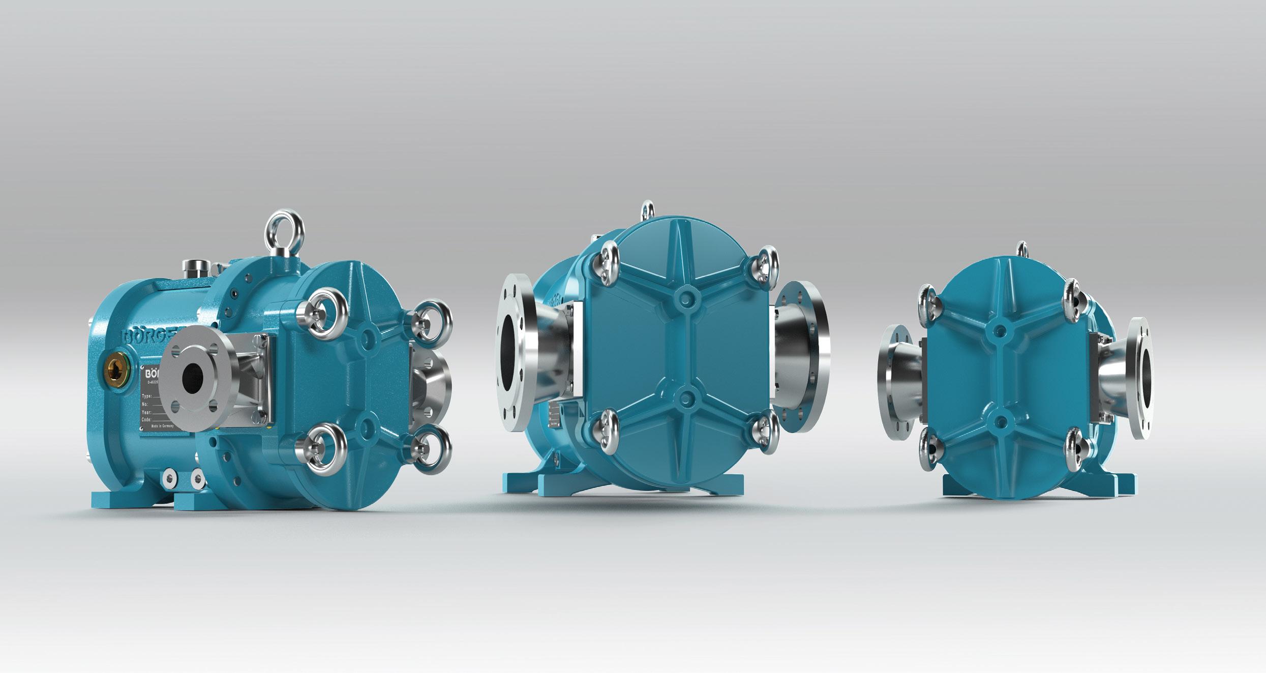
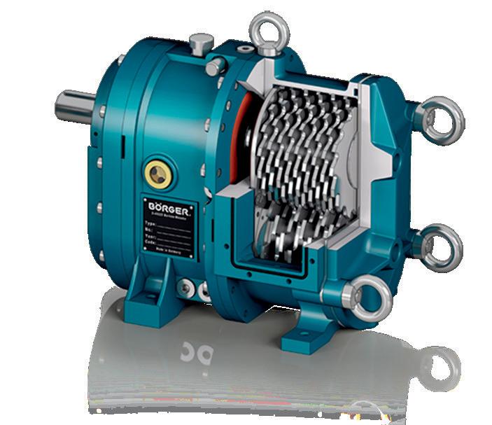
Boerger has surprised the world of pumps with a new generation of its BLUEline rotary lobe pumps, the BLUEline Nova, with the high-tech pump available in six sizes and with flow rates of up to 110m³/h. The German manufacturer promises not only excellent volumetric efficiency but also maximum choice of sealing systems.
Boerger is well-known for its highquality rotary lobe pumps with flow rates of up to 1,450m³/h. Presenting the new generation of its BLUEline rotary lobe pumps, Alois Börger, Managing Director of Boerger, said, “The development of the BLUEline Nova has benefited from our 30 years of experience in pump manufacturing. With the help of computer flow simulations and physical test bench hours, we were able to improve the pumps even further.”
Mr Börger said the rotors and casing were made for one another. This newly developed one-piece DIUS rotor ensures an almost pulsation-free pumping at pressures of up to 12 bar, while the wide sealing surfaces of the screw-profile rotor prevents backflow of the medium.
“Boerger has also modified the pump chamber to utilise the dual-lobe rotor to its full potential. The geometry of the inlets and outlets, as well as the wrap angle of the casing, were
particularly optimised. We were able to considerably improve the volumetric efficiency of the pump. To this end, we have adjusted the pump chamber to the rotor geometry in a flow-optimised design,” Mr Börger said.
The BLUEline Nova comes in two variants: with or without protection plates and liners. In its clean version, protection plates and liners are not required. The pump with minimum dead space can be cleaned according to the hygiene procedures, CIP (Cleaning-InPlace) and SIP (Sterilisation-In-Place).
In its tough version, the pump is equipped with protection plates and liners for pumping abrasive media containing solids. With a new innovative fastening system, the ‘tough’ version of the Nova pump ensures the best volumetric efficiency ever achieved in a rotary lobe pump. In case of wear, the protection plates and liners will be replaced quickly and easily due to its MIP® design (Maintenance in Place).
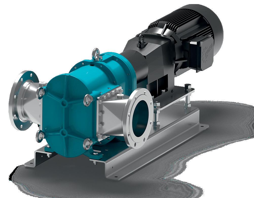
The large seal chamber of the BLUEline Nova provides space for different sealing systems, therefore ensuring connection of external supply systems is possible, and without issues. Different motors can also be selected for driving the BLUEline Nova rotary lobe pump. Upon request, the drive can be directly flanged to the pump and, due to the elimination of the coupling, the unit is now even more compact. In addition, this version does not require a base frame.
Like all Boerger pumps, the BLUEline Nova rotary lobe pumps can be manufactured according to the European ATEX guidelines for use in potentially explosive atmospheres. An API-676-compliant design, production according to the FDA regulations, or a technically tight pump design according to the German TA Luft requirements, round off the various options for versatile applications.
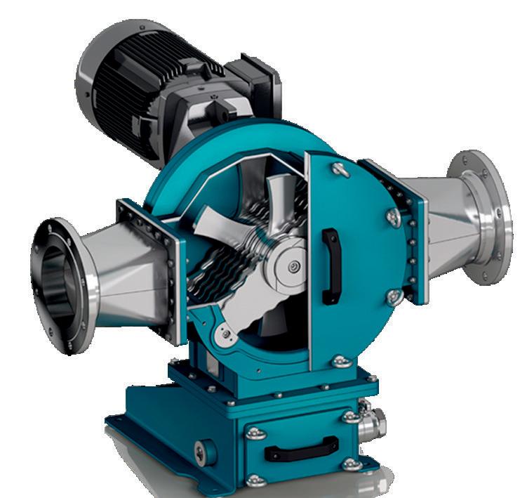
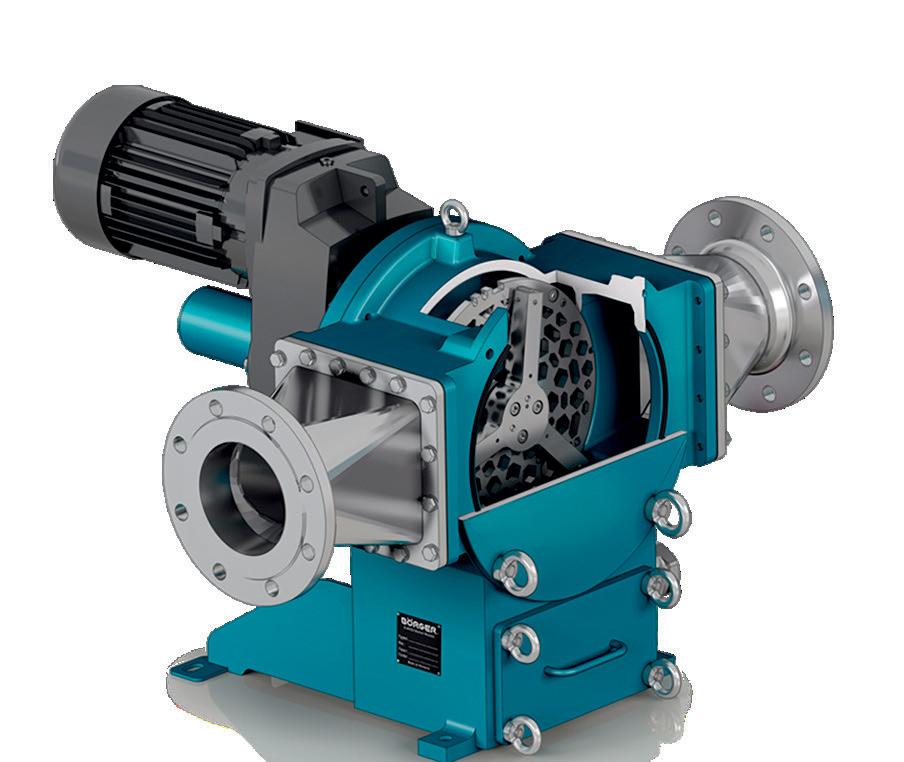
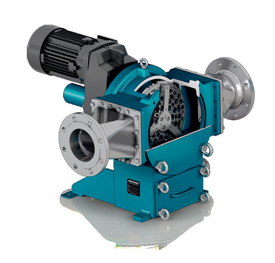
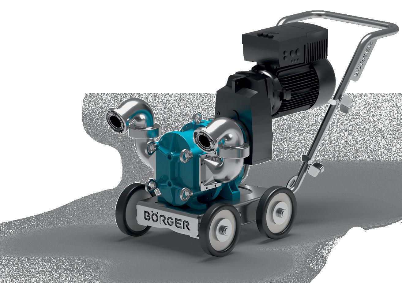
Mobile, stationary or submerged – Börger configures and builds each rotary lobe pump in line with the requirements of the specific application.
The application options of Börger pumps have expanded with the new B BLUEline Nova rotary lobe pump. The BLUEline Nova pump ensures the best efficiency even with high pressures. Börger pumps are available in 25 pump sizes with flow rates between 1 – 1,440 m³/h.
Further to this, Börger also offers three different macerators - providing efficient chopping operations and capabilities, ensuring downstream machines and pumps to perform smoothly.



Australian layflat hose manufacturer Crusader Hose has an excellent working relationship with leading pump companies. When a new thermal springs and spa resort needed to install some bore pumps, they turned to Franklin Electric, who then recommended Flexibore®, the flexible riser from Crusader Hose.
Crusader Hose has been manufacturing layflat hose for over 35 years and, during that time, has forged strong relationships with leading pump companies. Combining world-class submersible pumps and innovative layflat hose is the perfect solution for efficient groundwater extraction.
A layflat hose solution for water management
Alba Thermal Springs and Spa is being developed on the Mornington Peninsula in Victoria to meet the high demands of the luxury spa and wellness market. The property will offer guests the opportunity to enjoy geothermal springs in over 30 pools.
The brief for the project was clear; to establish a water system to manage the water cycle and treatment, ensuring that the full health benefits for patrons are achieved. The water infrastructure includes numerous holding tanks, pumps and pipelines. Therapeutic natural hot spring waters from the underground source need to be extracted with reliable pumps while risers lead the water to the network of pipes. The mineral-rich clean hot water is then piped into tanks from 60100m down, then fed into selected bathing areas.
Matt Bevil, Services Manager for Alba, has worked with these water management systems for many years and used his contacts to secure the best products for the project. His first contact was David Strang from Franklin Electric, a highly respected company that manufactures submersible pumps with corrosion-resistant and high-quality motors.
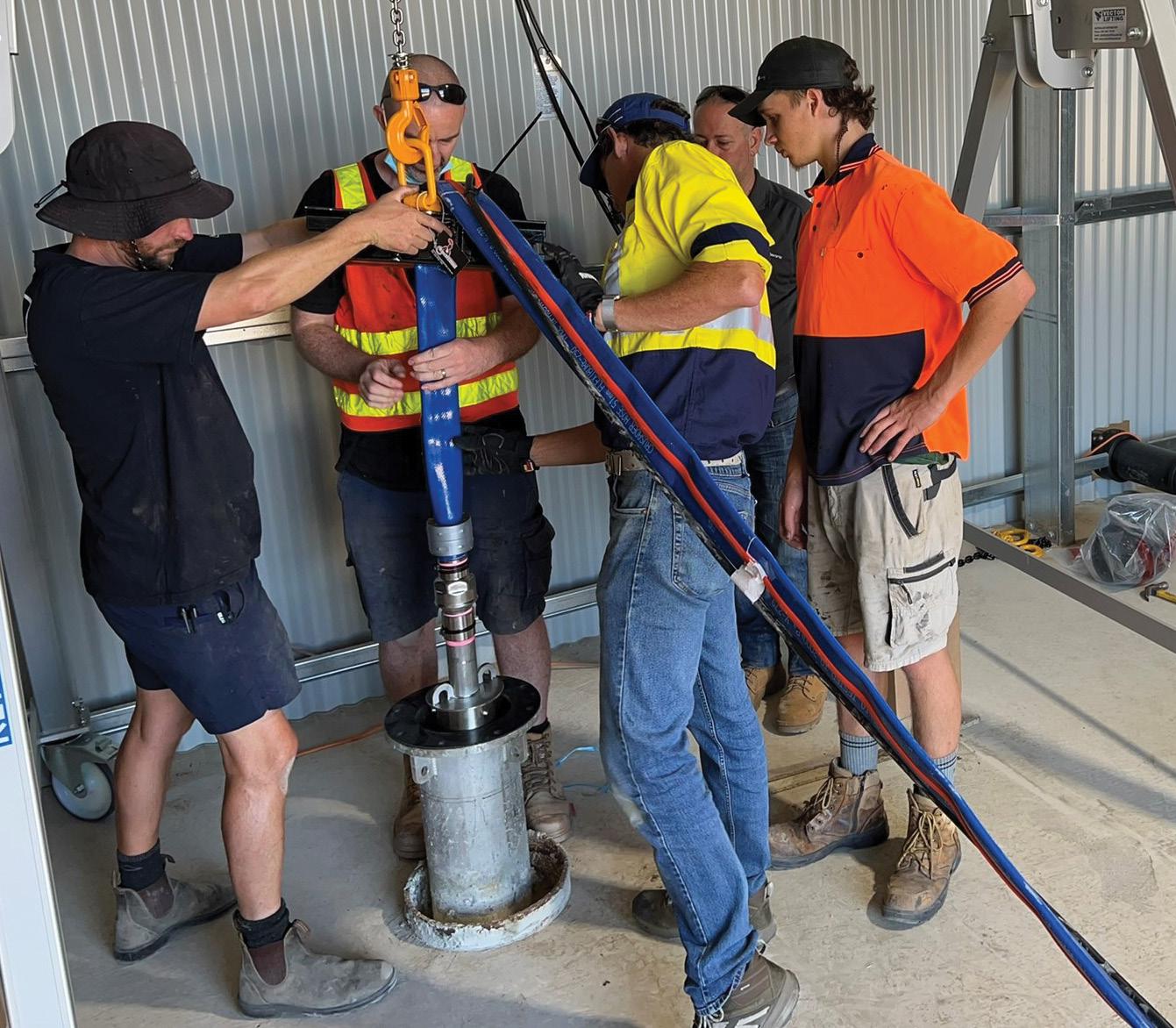
Franklin Electric has worked with Crusader Hose on other bore water pumping projects in the past and is familiar with the ease of installing Flexibore®, the flexible riser.
“Flexibore® is a reliable product and can be easily installed without too much fuss, saving time and money for the end user,” said David.
Superior construction and easy to install
Flexibore® is not only easy to use, but its superior construction enables it to handle temperatures of bore water, sometimes exceeding 80°C. For new installers, it’s always helpful to have an expert on hand for tips and guidance; Francois Steverlynck, Managing Director, was happy to accommodate.
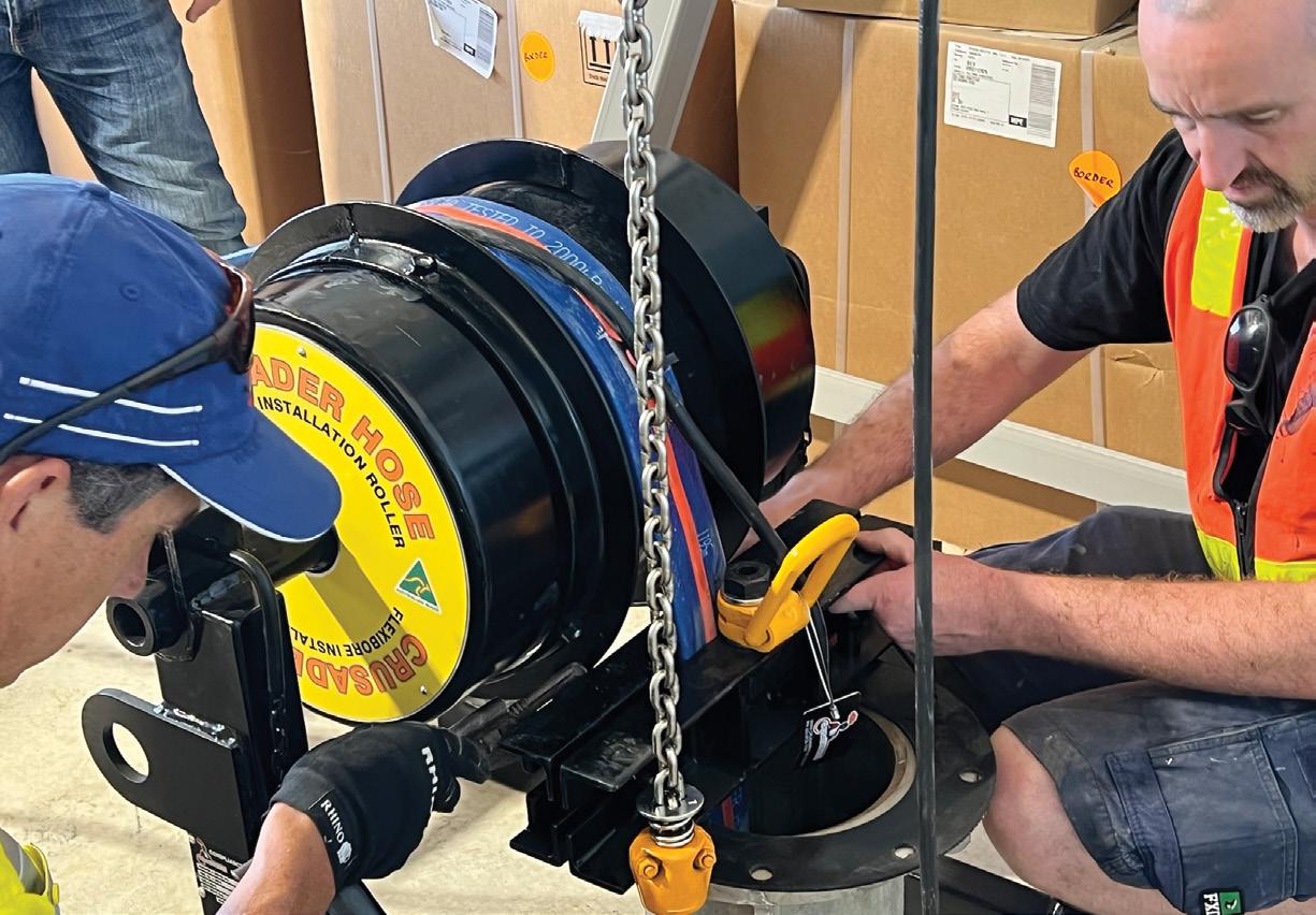
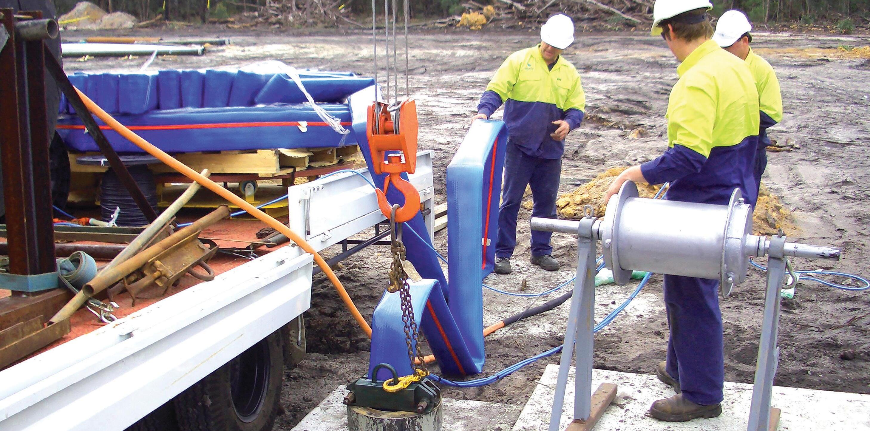
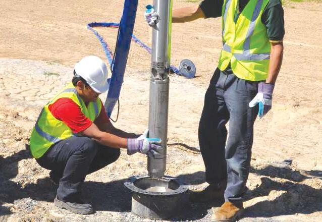
With plenty of room to lay out the hose, two workers attended to the snaking of the electric cable and their attachment to the hose. A guernsey was used to lift and insert the pump and later the bore cap. Flexibore® accessories such as lifting clamps and an installation roller made the work relatively straightforward. A 4x4 truck was all that was needed to install the 60m Flexibore® hose.
“Working with our customers is always a pleasure. We know Flexibore® makes bore installations so much quicker. To receive the positive feedback from Matt and his team reaffirms our commitment to developing the most efficient water systems in Australia,” said Francois.
Alba will open later this year so that discerning bathers can enjoy the reinvigorating effects of thermal water. Enjoy!


Contact us today on +61 3 9720 1100 or email sales@crusaderhose.com.au to learn more or request a quote! Flexibore® it with hydrolysis-resistant polyurethane.

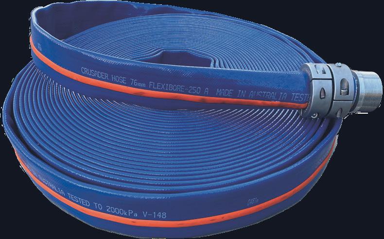
Proudly manufactured in Australia by Crusader Hose, Flexibore® 250 is made to suit most bore water pumping applications and is manufactured in a large range of diameters from 40 mm to 152 mm, in continuous lengths of up to 250 m.
With a high burst pressure for deep bore water pumping, the Flexibore® 250 can handle the weight of the pump plus water up to 250 m without a safety cable.
Quality you can trust
Deep ground water pumping up to 250 m
Ultra-high tensile strength for large submersible pumps
Flexible, so easy to install & retrieve
Swells up to 15%, avoiding internal build-up
Rigorously tested
Secure couplings
Lower pumping costs and friction loss
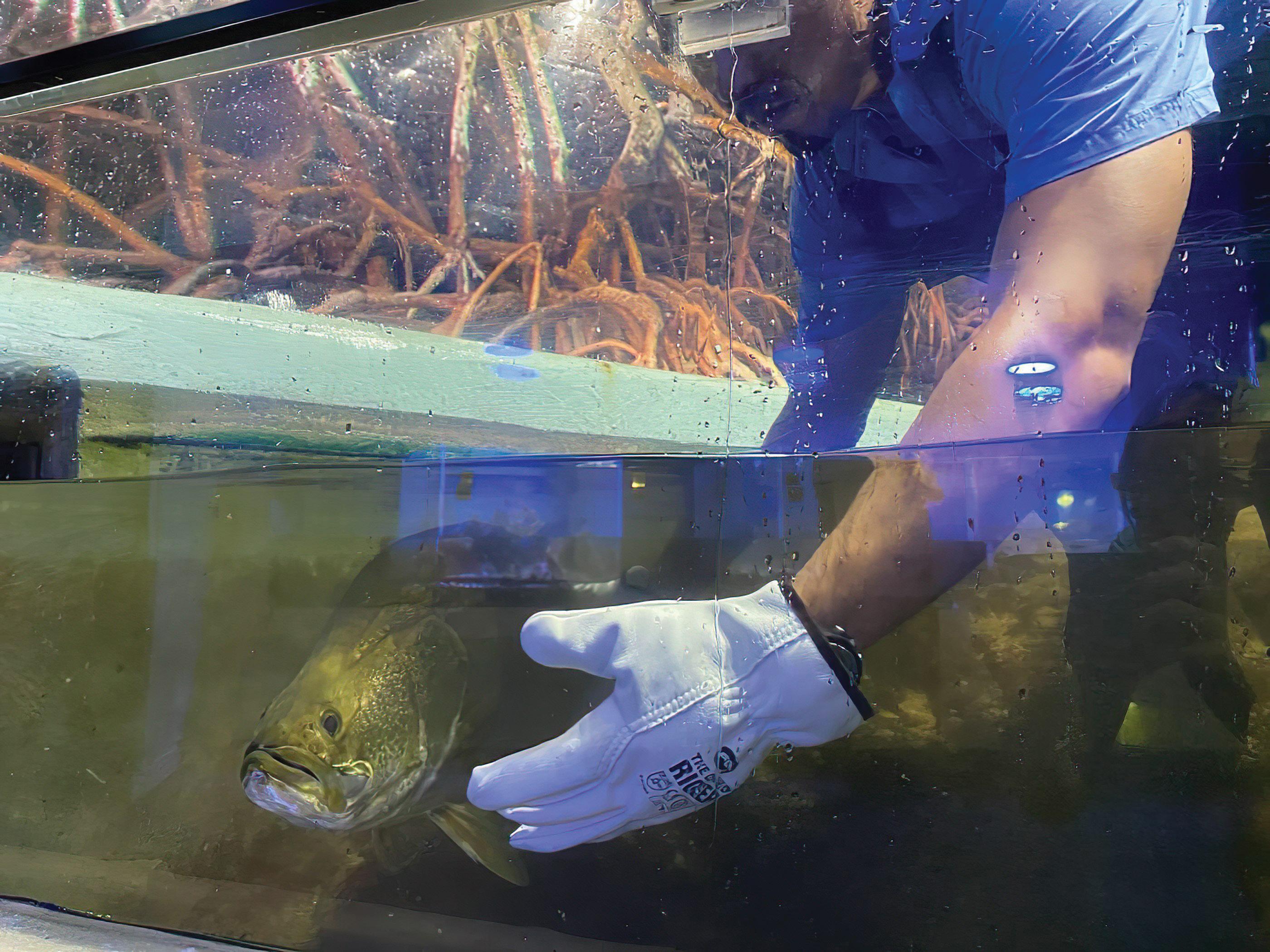
Aquarists corralling the barramundi ready for relocation within Reef HQ Aquarium.
Reef HQ Aquarium in Townsville is the world’s largest living coral reef aquarium and was originally designed to make experiencing the wonders of the Great Barrier Reef accessible and affordable, while also spreading the Reef conservation message and gaining public support for the protection of the ‘real thing’. However, since its opening in 1987, the aggressive tropical environment of the region and the stress of holding in excess of four million litres of saltwater have impacted the facility, resulting in the need for a major refurbishment and upgrade of aging infrastructure to ensure optimal operation. Pump Industry spoke to Sasha Thyer an expert at Reef HQ Aquarium about the redevelopment and upgrades, including those undertaken to the plant room, fire systems, life support systems, and hydraulic systems.
Since the transformation of Reef HQ Aquarium began in 2019, the Australian Government has committed $80.1 million to develop a global centre of excellence in tropical coral reef education. The works are occurring in stages with early works undertaken to improve aquatic life support systems.
The early works program focused on a number of projects that primarily aimed to resolve critical safety issues, as well as other works required to relocate and upgrade connected systems at the same time.
“The early works program was necessary to address the most urgent rectification requirements of aging critical systems at Reef HQ Aquarium affecting safety, function and animal life support systems,” Ms Thyer said.
“Fundamental building services required replacing or upgrading, including the building’s electrical network, elements
of the Heating, Ventilation, Air Conditioning, Chilling and Refrigeration (HVAC&R), building structural elements, and animal life support systems.
“The Aquarium is 35 years old, and located in a hot, humid seawater environment in North Queensland, which requires highly durable equipment and systems. It is also unique in its function – being home to the largest living coral reef aquarium, with a total of four million litres of seawater being integrated into the building structures. The Coral Reef Exhibit (CRE) requires 24/7 uninterrupted power and stability for key water quality parameters, thus system failures can become critical quite quickly.”
Careful and highly detailed programming and contingency planning began more than 18 months before the site was handed over to a Principal Contractor to manage the remaining scope of works, including likely latent issues that may be exposed during the construction phase.
“Space in the building is limited, so efficient use of space was also important. Due to the severe weather season in North Queensland, careful scheduling had to occur and there were many dependencies relying upon government permissions and other permitting authorities (such as the electrical network provider),” Ms Thyer said.
“A core limitation and complexity for the project was that continuity of basic building services such as power, chilling systems and pumping systems had to be maintained to ensure animal life support systems were not interrupted for more than two hours. Backup systems were required to guarantee the two hour window was not exceeded, and major construction activities had to be avoided where possible during the severe weather season.”
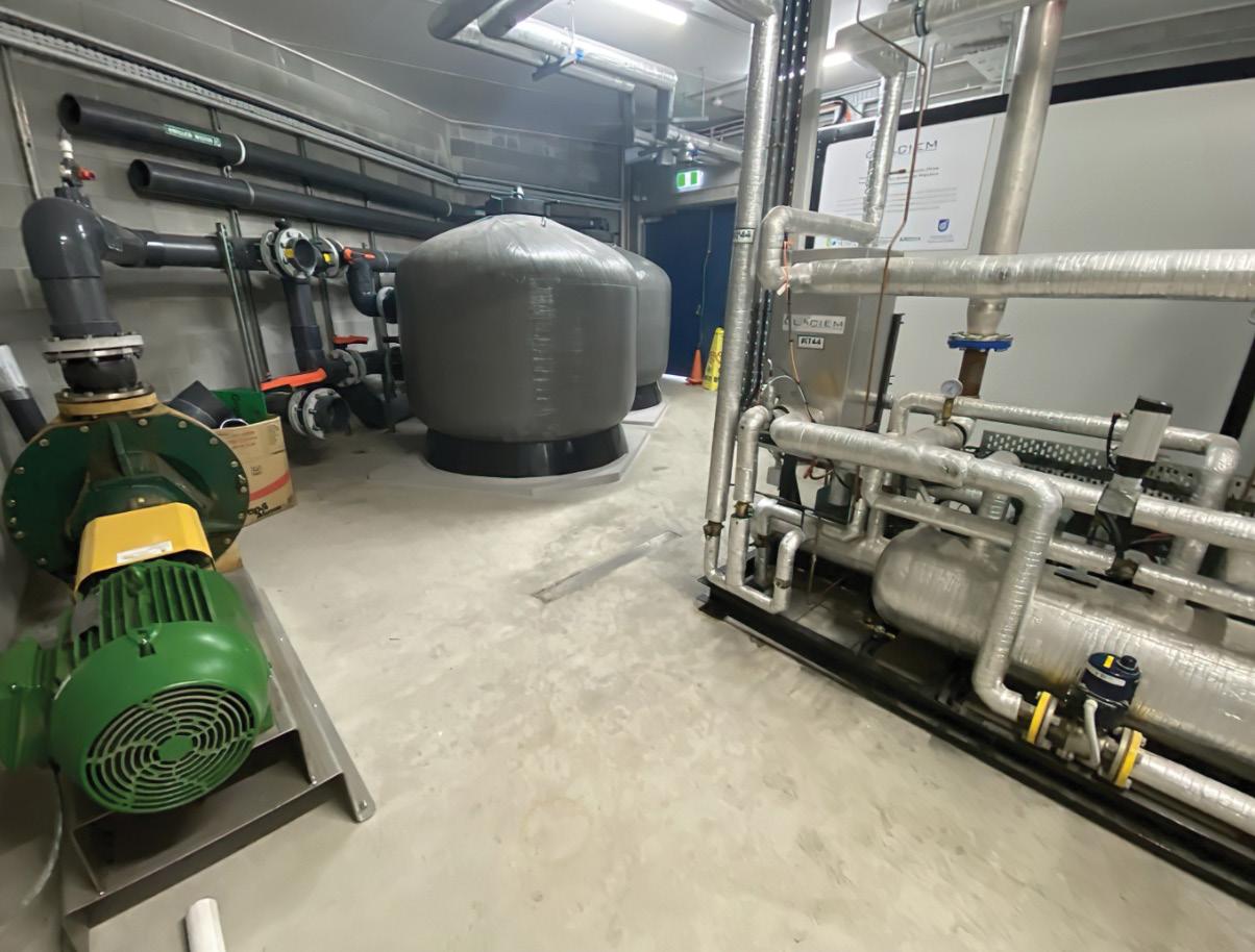
New plant rooms were built on level one directly above an exiting substation to house electrical and mechanical services, including the thermal energy storage unit, life support systems, electrical battery storage and the main switchboard. Some of these services required relocation due to works and changes in their existing locations, and others were new to Reef HQ's operating systems, but were implemented to improve energy efficiency.
One of the main projects was the replacement of the Aquarium’s main electrical switchboard (MSB), originally installed in 1986, and associated distribution switchboards. As the existing plant room had been subject to subsidence and was potentially exposed to flooding, it was relocated from the ground floor to the first floor. Due to the requirement for no power interruption, and to allow a smooth changeover and minimal power interruptions, the existing MSB had to remain in place until the new MSB was operational. At the same time, an old substation containing 35-year-old transformers owned by Ergon Energy had to be replaced and relocated to a padmount transformer in a different location.
Ms Thyer said that this had knock-on effects, requiring other major systems to be relocated.
“The coral reef exhibit heater and animal life support systems had to be relocated to make way for the padmount transformer. The solution to all these challenges was to construct a new plant room directly above the substation to contain the new MSB, heater, thermal storage and life support systems,” Ms Thyer said.
“This occurred whilst all the existing systems stayed operational. New foundation piles had to be installed to accommodate the new structure, and other systems required protection from the construction works. Meticulous planning, scheduling, risk management and communication was required to ensure all scenarios were planned for and all phases ran smoothly.”
the plant room
A fundamental corporate principle for the Great Barrier Reef Marine Park Authority is sustainability and energy efficiency in the delivery of its services. The upgrades provided an opportunity for sustainability improvements to be made, such as the use of high efficiency pumps and locating life support systems to minimise pumping power.
“Major retrofit actions rarely occur in the life of most buildings so it is important to seize the opportunity for improvements across all levels of service. Every project involved greater efficiency through a range of mechanisms including guiding principles of the circular economy,” Ms Thyer said.
“Materials and equipment were reused where possible or recycled. Design of every system was reviewed, even if the
requirements had not changed. The integration of system efficiencies was considered overall, reviewing elements such as cable and pipe distances, location of supporting equipment and structures, maintenance requirements, system lifecycle costs and energy use, and smart building management systems.
“High efficiency pumps were chosen, and life support systems were located in order to minimise pumping power and requirements. The new pump room services included the main electrical system (MSB), solar power inverters, and associated electrical battery storage system, communications equipment, a new thermal storage system (ice), animal life support systems and heat exchangers.”
The relocation of the Predator Exhibit life support system resulted in no additional energy use for filtration pumping, but has provided greater efficiency for cooling/heating (heat exchanger) due to its closer proximity to the Aquarium exhibit.
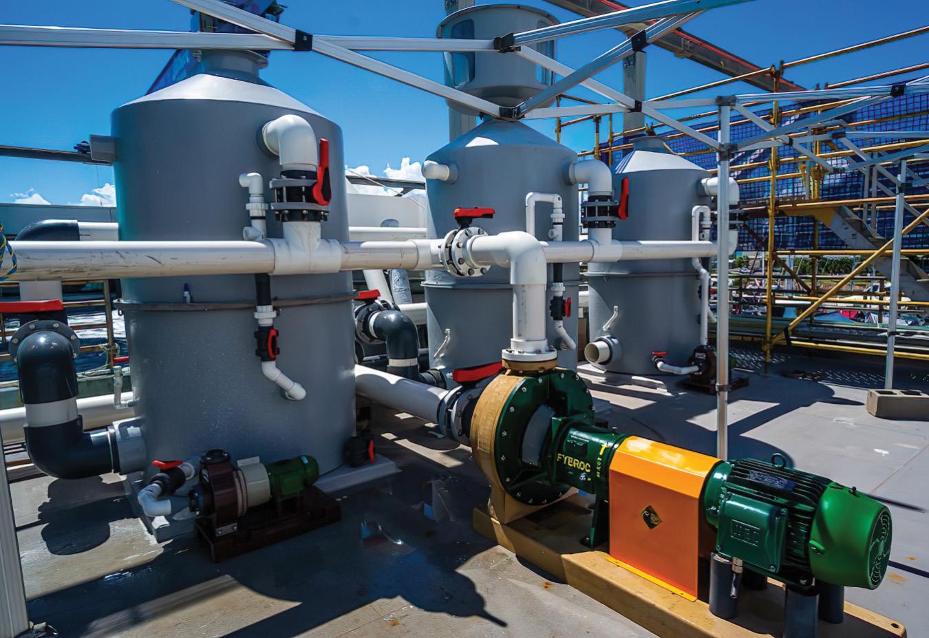
Ms Thyer said the relocation of the Coral Reef Exhibit life support system resulted in significantly greater efficiencies, as the design was changed to reduce pipe distances (horizontally and vertically), and pumping requirements were reduced by utilising more circulation pumps inside the tank and less sand filtration, which was previously used excessively.
Furthermore, recycled glass was used in the sand filters to improve flow and reduce compacting.
The wave machine, which supports the coral reef exhibit, was also refurbished for longevity and greater efficiency. One of the most important improvements to efficiency was to optimise the location of equipment to minimise friction losses through pipework and pumping heights.
“The Coral Reef Exhibit foam fractionator and ozone system were also redesigned to minimise pumping head height, and we were able to take advantage of low-head pico-hydro turbines to recover energy returning to the main exhibit tank. The pico-hydro generators (which are a turbine-style generator) are capable of recovering 10,000kWh per year, which is fed straight back to the building’s electric network via inverters,” Ms Thyer said.
“We were also able to use rejected heat from the chilling system (the new thermal storage system) to heat the Coral Reef Exhibit in winter – this created significant efficiency for energy and space.
“New system controls on the Coral Reef Exhibit wave machine allowed more control to finely tune the system for greatest efficiency, to find the optimum wave height and frequency.”
The Aquarium was already utilising a 20kL chilled water thermal storage system to minimise stop/start of the HVAC main chillers and shave the facility’s peak power load. While this system was working well – and was relocated to the new plant room above the old substation – the 216kW solar power system was generating a surplus during the highest solar radiation periods. As the electrical network provider did not require power export back to the grid, the surplus power was being wasted.
A solution to this issue came with an invitation to partner with Glaciem Technologies under the Advancing Renewable Program co-funded by the Australian Renewable Energy Agency (ARENA).
“Our commitment involved working through complexities in a real-world setting to refine the technology. The project included the installation of a new thermal storage system using phase change materials (ice), a carbon neutral refrigerant (CO2) and 50kW of additional solar panels for the existing solar power system,” Ms Thyer said.
“As the existing Coral Reef Exhibit filtration system had to be moved to make way for the new padmount transformer, on request by the Reef Authority, the design of the new thermal storage system also incorporated energy recovery by utilising the system pumps to redirect waste heat to the Coral Reef Exhibit in winter.
“This may seem counterintuitive, however the Aquarium building requires space cooling for all but two to three weeks of the year, whereas heating is required for the Coral Reef Exhibit for three to four months.”
Energy efficiency results
The Aquarium is still collecting data and tweaking and refining the systems as there has been a drop in power requirements due to COVID-19, and some systems have been decommissioned as Reef HQ was closed to enable major works to occur.
While this has made it difficult to precisely determine the overall savings, Ms Thyer said significant savings are evident through the design and relocation of the animal life support pumping systems.
Furthermore, 50kW of new solar power was added to the solar system, bringing it to a total of 260kW, and the new thermal storage and heating system, which uses heat generated by the chilling system to heat the Coral Reef Exhibit in winter, has eliminated the need for a dedicated heater (48kWr heating capacity). The pico-hydro generators will recover 10,000kWh per year from the Coral Reef Exhibit life support system, which represents ten percent of the pumping power required for the system.
Fire system upgrades
Both wet and dry fire systems were upgraded to meet current standards, and were triggered by works associated with the relocation of the main switchboard. The wet fire hydrant system included a connection manifold to the Townsville City Council mains water system and involved the installation of a fire hydrant booster pump.
Ms Thyer said the fire hydrant booster pump project was a huge challenge, particularly when it came to the space and correct location for the fire hydrant booster pump and space for the reticulation pipework.
“To bring the building's emergency systems up to the modern standards, the booster pump and associated pipe network were required. Reticulating the large pipes around an existing building that contains four million litres central to its main structure was an enormous design challenge,” Ms Thyer said.
“Locating the fire booster pump to comply with proximity requirements adjacent to the new padmount transformer and other building structures seemed like mission impossible and required an underground stormwater drain to be relocated to accommodate it.
“A major setback for this project was that the final test of the mains water pressures resulted in inadequate mains pressures. This was due to the mains water system pressures changing during the construction period. Resolution of this issue was pushed forward into the major works.”
Upgrading mechanical and hydraulic services
A number of mechanical services required replacement as they had come to the end of their life, including other upgrades to the wave machine’s air delivery system, motors and pneumatic equipment, and new blower motors.
Ms Thyer said the wave machine was originally installed by Boes Technology in 1986 and was functioning remarkably well, delivering a wave every eleven seconds, 24 hours a day, 365 days a year for 35 years.
“It is a beautifully simple, effective and energy efficient system. It delivers a huge volume of laminar flow through the entire exhibit, and this is supplemented by turbulent flow which is directed by low voltage, carbon fibre circulation pumps inside the exhibit,” Ms Thyer said.
“Laminar flow is important to the coral colonies as it pushes water through the coral heads, and this allows gaseous exchange and the removal of waste. It also allows waste to be blown out of the rocky substrate and keeps all areas oxygenated.
“The original blower motors were 75kW which could deliver a massive wave, much larger than required. The blower motors were at the end of their life, so they were replaced with a 40kW high efficiency motor, with a new variable speed drive and upgraded control system.
“In 2016, the other parts of the system (the compressors, receiver, air dryer and ducting) were replaced and thus in 202021 were still in good working condition. The system design was found to be still relevant and efficient, so only modernisation of the control system was required.
“Commonwealth procurement processes were followed for this work which was relatively low value and, in this case, involved quotes from numerous local suppliers and installation by a local technician.”
Some hydraulic services were modified, replaced or repaired as part of the retrofit actions in other works, including an overhaul of the creekwater intake system to mitigate the risks
of failure. Some preliminary works were required to address failed valves, pipework and pump seals, and the larger upgrade will include a complete review of the creekwater intake system, to mitigate risks and maximise efficiencies.
Upgrading life support systems
In May 2020, the Aquarium received $2.6 million in funding from the COVID-19 Relief and Recovery Fund to assist Great Barrier Reef Tourism and the North Queensland regional economy. This investment was used to upgrade the crucial animal life support systems that were at the end of their life, and some systems that had already partly failed or become inadequate to meet modern standards. One system had to be relocated to enable some building structural repairs.
The animal life support systems maintain critical parameters for inhabitants of the Aquarium to thrive, such as oxygen, low nutrients, low pathogen levels, optimum salinity, temperature, pH and calcium levels.
These systems also enable the intake of new seawater from the adjacent Ross Creek. During the severe weather season, the system can remove freshwater via reverse osmosis to maintain salinity within critical parameters.
Ms Thyer said meticulous planning was fundamental to the success of the early works as scheduling had to take into account the severe weather season, long lead times on equipment, government permissions, and crucially, the requirement to maintain the operation of most of the systems throughout the construction phase.
“There were many interfaces between projects and where building structural work was involved, latent issues associated with an old building were likely. Contingency planning was very important with room in the schedule and budget to accommodate any issues that may arise,” Ms Thyer said.
“The projects involved a lot of highly specialised equipment, so the right expertise was critical to smooth implementation and also good communication between the Reef Authority team, Project Manager and the contractor’s Project Manager.”
Upgrading the reverse osmosis machines
The reverse osmosis (RO) system uses very high pressure pumps to push seawater into a membrane where the freshwater can travel through (the ‘permeate’) and the concentrated saltwater (the ‘concentrate’) is left behind. In other settings, RO is usually used to create drinking water from seawater or contaminated water, but at the Aquarium it is used to remove rainwater from the large open topped aquariums to maintain the correct amount of saltiness (salinity). It can
also correct the salinity of new seawater water taken from the adjacent the Ross Creek.
The reef tank inhabitants are very sensitive to changes and the salinity needs to be maintained at 33-35ppt. During severe weather seasons, huge rainfall can occur – in 2019 the region copped 381mm rain in 24hrs and 277mm in just three hours – and the salinity can only be adjusted by RO or the addition of salt. Ms Thyer said RO is preferred as it can be activated automatically when staff are not on-site and does not involve manual handling of salt.
The Aquarium's old RO system was at the end of its life and had failed completely during the 2019 wet season which saw a once in 100-year flooding event. This meant that 40 tonnes of artificial salt had to be added by hand (20kg bag at a time) by staff over a four day period.
The old system could remove 27,000L of freshwater per day while the new system can remove 45,000L per day.
Ms Thyer said the new system provides resilience and redundancy in the overall system, mitigates risks associated with flooding, and also helps to manage the variety of events that can occur.
“The new systems are better protected from the elements (some outside systems were moved into the new plant room) and moved out of areas that could possibly be exposed to flooding. The new foam fractionator system includes a degassing reservoir to ensure that no residual ozone can enter the Aquarium tanks,” Ms Thyer said.
The ozone configuration and dosing was improved to allow for optimal removal of waste products, and the systems were made safer for staff to operate and more energy efficient. The energy efficiency improvements mean the emergency power system is able to service more equipment for longer.
“RO systems are specialised, however, there are quite a few options available in the marketplace. In this case, the Aquarium requires a medium sized system (not a domestic sized system and not a municipal water sized system), so the number of options for size and other requirements – such as short lead time and specific technical requirements and local support –narrowed the field,” Ms Thyer said.
“The Commonwealth Government has mandatory procurement processes that must be followed. In this case, a number of suppliers were approached to quote on the new system and the urgency of the project was an element in the procurement method chosen.”
Commencing back in 1962 in Dandenong, Victoria, close-by its present site, Franklin Electric began importing and distributing 4” submersible products. Soon after, local manufacturing commenced with specialised imported parts to offer the Australian water industry Franklin’s world-leading 4” submersible motors.

Over the decades, Franklin Electric motor products were designed and evolved to provide the industry with the highest quality 4”, 6”, 8”, 10” and 12” submersible motor products available.
The main benefit that the Australian industry has come to rely on from Franklin is its quality, reliability and performance. Franklin demonstrates these every day to its customers through its Five Key Factors for Success: quality, availability, service, innovation and cost.
Franklin submersible motor products became Australia’s leading submersible motor and indeed the world’s most installed submersible electric motors.
Franklin had been partnering with pump manufacturers for decades and had developed a deep understanding of the market. When the industry started to consolidate around the world in the late 1990s and early 2000s, Franklin had some serious decisions to make.
automatic self-priming pumps, as well as solids handling selfpriming pumps.
Outside of the US, Pioneer Pump has factories for fabrication, and assembly and warehousing facilities operational in South Africa, England and Australia.
In 2011, Franklin Electric agreed to purchase the remaining 65 per cent of Pioneer. In 2020, Franklin Electric decided to consolidate its water business group globally under one Franklin Electric company.

In 2004, Franklin Electric announced the purchase of JBD (the former Jacuzzi industrial range), and that it was entering the pumping industry by launching Franklin Pumping Systems, now known as FPS. Starting from a very low share, FPS is now leading the US market.
As the pumping industry is global, similar issues applied in Australia. In late 2007, Franklin Electric Australia, after three years of evaluating the market, entered the main water pump industry by launching and distributing its FPS range of submersible pumps and above ground pumps, motors, drives and controls direct to its own Australian dealer network.
In 2005, Franklin Electric purchased a 35 per cent stake of Pioneer Pump Inc, situated in Canby, Portland, Oregon. Pioneer manufactures a large range of centrifugal pumps and
Today, Franklin Electric Australia and Pioneer Pump Holdings Australia are one company, Franklin Electric Australia New Zealand Pty Ltd, with two facilities operating: the warehouse and assembly facility in Dandenong South, Victoria; and the fabrication assembly and test facility in Sunshine West, Victoria, which includes a logistic warehouse in Ravenhall, Victoria.
Along with the consolidation of the businesses comes the staff and the years of pump experience, the company has hundreds of years of experience to assist every person who needs help with a pump or application.
An expanding range
Today, the range of products have expanded to:
• A full range of surface mount pumps, ISO, split case, multistage, small and large centrifugal motor pumps, progressive cavity (MONO TYPE) and self-priming ranges, small volume low head, to extreme high volumes (2500 LPS) and discharge heads exceeding 300m
• Solar pumps and pumping equipment
• A huge range of belowground pumps: submersible turbine, line shaft, bore hole and dewatering
Truly one of the largest and most comprehensive ranges of pumping and associated products supplied by a single company globally.
“Moving Water Moving Forward”
Maxijet is driven to be the industries most trusted source in customer service, technical, aftermarket support and industry solutions for the conservation of our most important global resource. We pride ourselves on being the industry people who care.
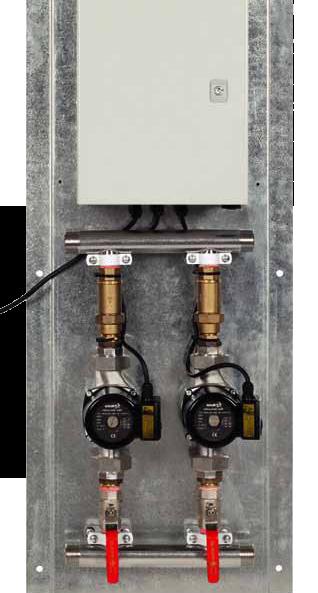
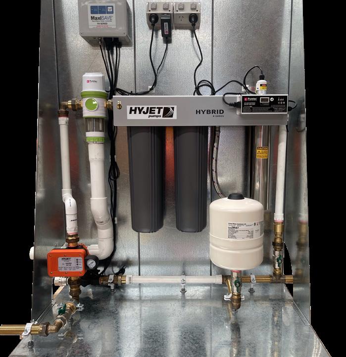
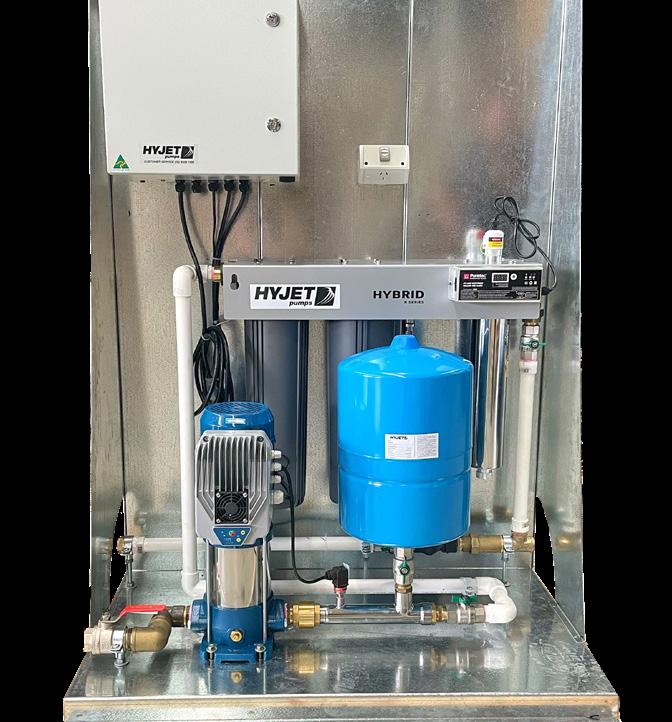
Custom made rain water re-use, hot water circulator, and water boosting systems. Maxijet Australia is committed to manufacturing the best pump systems for water conservation.
Available in many configurations to suit your flow requirements or any project specifications. All manufactured locally in our Melbourne factory.



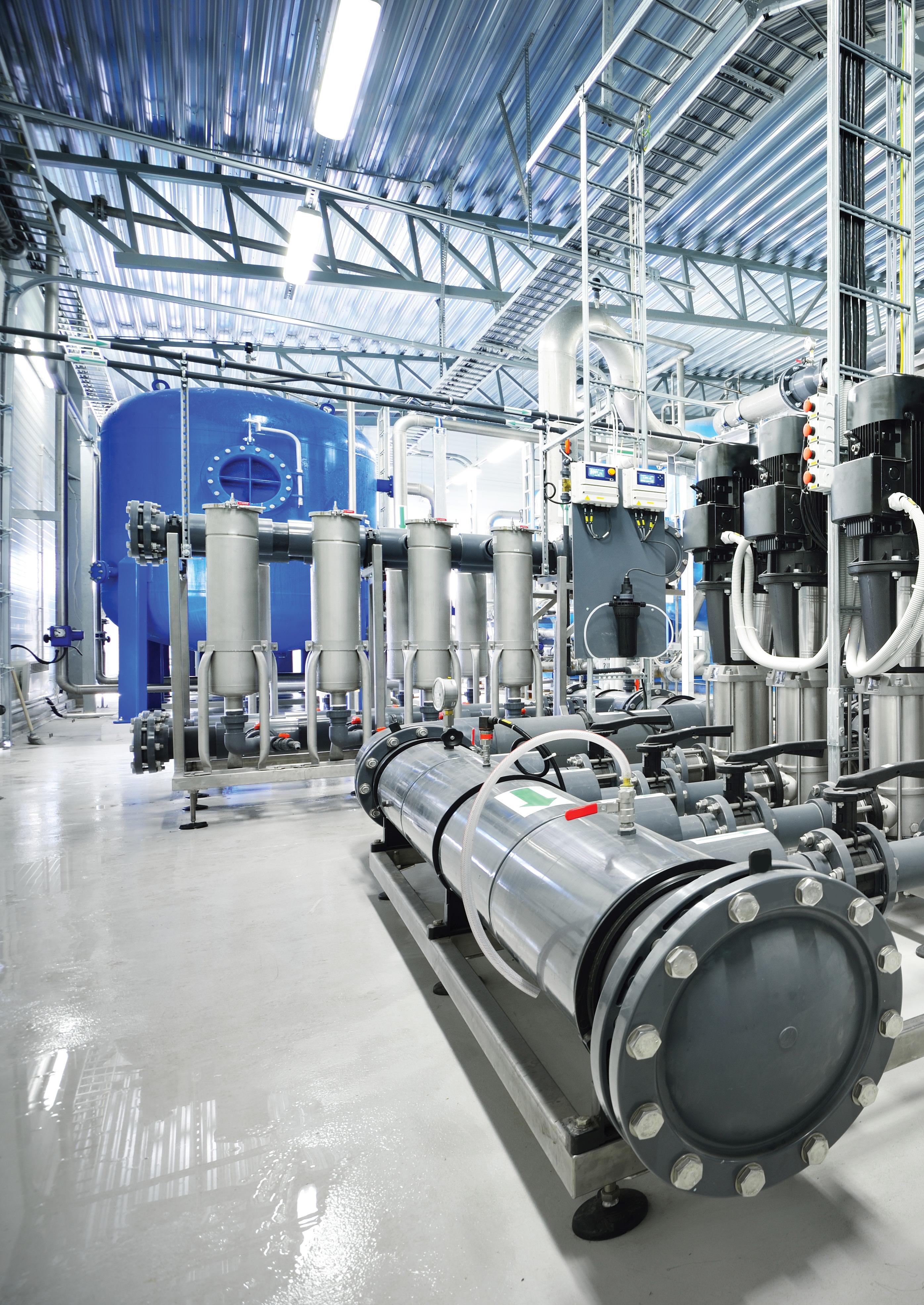
For more information on Hyjet and Pedrollo products and expert advice to help you choose the right solution for your project, contact us today!


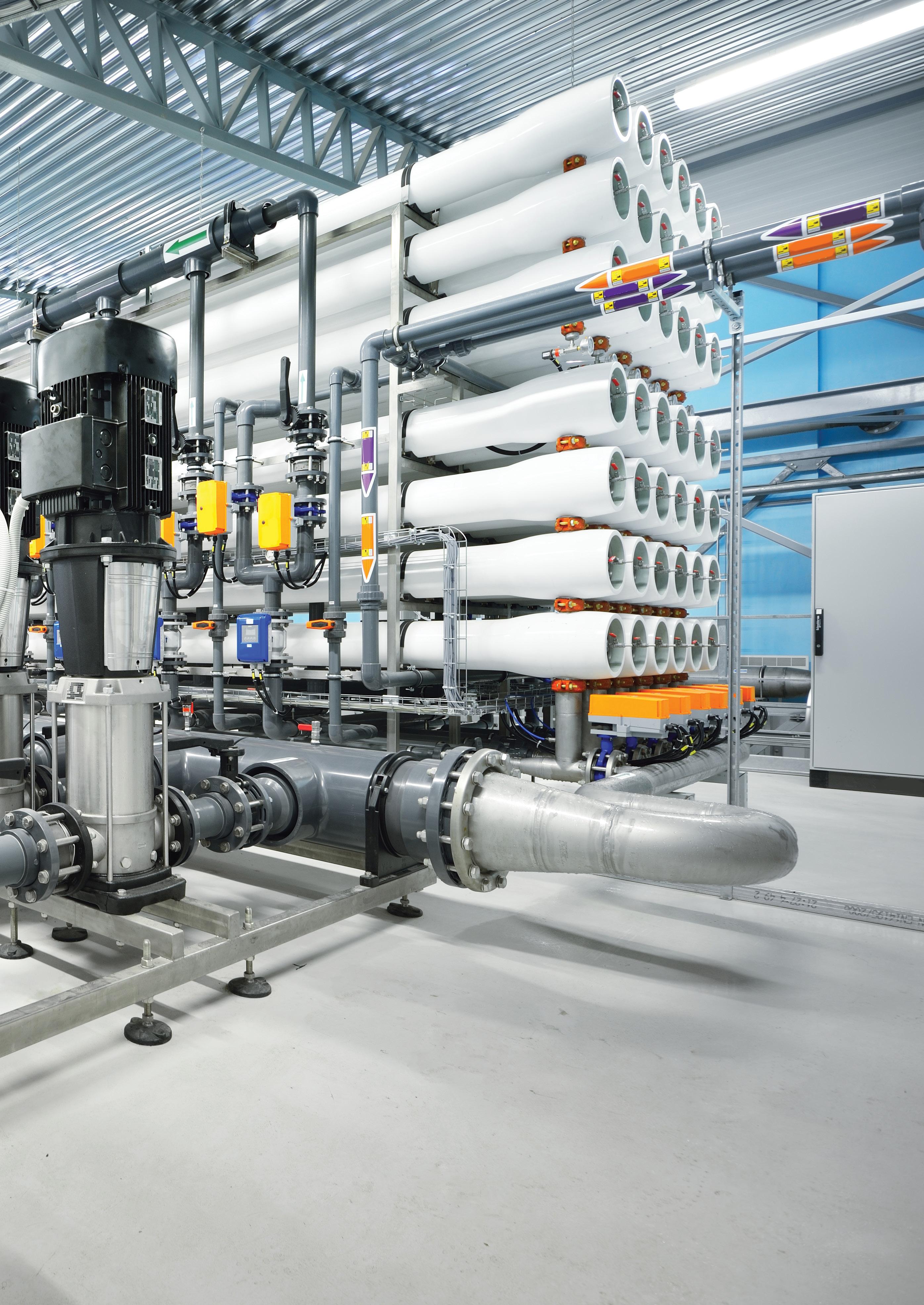
Reverse osmosis (RO) is a filtration process where pressurised water is passed through a membrane to produce purified water, used across countless industrial applications including desalination and industrial wastewater treatment. In the context of minimising global energy consumption, water utilities and asset managers are now measuring their water treatment systems against both sustainability and cost outcomes, with new insights for RO pump selection. Here we explore how RO works, the types of pumps involved in different industrial applications, and how the right pump selection can meet both sustainability and cost reduction outcomes.
Reverse osmosis (RO) is a water treatment process where a raw water source, such as seawater, is separated into purified water and a concentrated waste of dissolved salts, minerals, bacteria, and other matter.
By pressurising water through a semipermeable membrane, RO pumps produce purified water in countless industry applications, from desalination plants to industrial wastewater treatment.
A core principle found across all these industry applications is that the pressure of the RO pump must be great enough to overcome – or “reverse” – the osmotic pressure that keeps unwanted particles suspended in the raw water source.
Given that RO pumps must work against osmotic pressure, it is essential that the selected pump has high-pressure capabilities, holding implications for the minimum amount of energy required for the pump.
Indeed, it is estimated that RO pumps in a desalination plant can consume about 50 to 60 per cent of the total energy used by the plant; selecting a more energy efficient RO pump can easily carry across to total plant energy savings.
In terms of pump selection, for many years, centrifugal pumps were considered the best choice for RO, however, single stage centrifugal pumps – although popular across a range of water applications – cannot typically reach adequate pressures to
achieve reverse osmosis. Increasingly, water-lubricated axial piston pumps (AP), coupled in trains, are being used to provide the most efficient and flexible solution to meet the changing water demand.
When comparing the energy efficiency of centrifugal and axial piston pumps across different pump configurations and flow rates, manufacturers have found energy savings of up to 16 per cent when using a high-pressure pump for RO, compared to the centrifugal setup across a variety of parameters. Such energy savings have been documented in both test studies and the operations of plants worldwide.
Alternatively, triplex piston pumps, side channel pumps and multistage pumps are also frequently selected for reverse osmosis treatment systems, offering adequate high pressure capabilities.
While axial piston pumps are highly competitive in small and medium-sized RO plants, a hybrid solution drawing on both high-pressure centrifugal and axial piston pumps could be the best solution to deliver an efficient water desalination system for large urban water purposes. Indeed, hybrid RO pump solutions can be ideal when retrofitting or upgrading larger existing pump systems, offering reduced upfront costs relative to complete system replacement yet still achieving an energy consumption reduction.
Different industry applications will also have different requirements of RO pump selection, with relevant factors including the chosen raw water source, the scale of the system and purification task, and the exposure of pumps to corrosive waste products.
One of the most common applications of reverse osmosis, desalination involves the purification of seawater into fresh water for human consumption, washing and other uses.
Desalination plants come in vastly different scales, from the seawater RO pumps found on modern ships to large, land-based desalination plants that provide municipal water supplies throughout the world.
Desalination RO pumps are typically constructed of materials like bronze and stainless steel, which have corrosion resistance to fluids with salt content.
Furthermore, different levels of salt content in the raw water source will affect pump pressure – seawater RO pumps will require higher pressure levels when compared to desalination plants for brackish waters.
Countless industrial processes rely on large amounts of water, from manufacturing to cooling of machinery, and reverse osmosis can help treat industrial wastewater for hazardous residues like chemicals and oils, creating clean water for further use.

Industrial wastewater treatment tasks will vary greatly, as will the appropriate reverse osmosis water pump.
For example, the wastewater created in a recycling plant could contain highly corrosive fluids, with downstream considerations for pump material selection.
Food and beverage industry
Food and beverage production processing is another industrial application for reverse osmosis systems, with a key consideration for pump selection being whether the system needs to be food grade.
Examples of reverse osmosis in the food and beverage sector include use in the dairy industry to separate whey from water and obtain concentrated whey protein, or even in maple syrup production, where water is derived from tree sap before it is boiled down to syrup.
Sustainability in water systems: an opportunity for savings
With the water sector responsible for four per cent of global electricity consumption, major utilities and asset managers have an important opportunity to retrofit and upgrade pump infrastructure to cut energy consumption, and associated costs, wherever possible.
A project in Italy highlighted that opportunities to reduce energy consumption in RO water treatment systems can be dramatic.
High-pressure RO pumps were selected for the tender of a new ultrapure seawater RO plant for a power company. The required specifications were that the desalination plant needed to have the capacity to provide 12,000 cubic metres of ultrapure water per day, cut the electricity consumption and carbon footprint, and complete the job quickly without any infrastructural modifications.
Four containerised RO units were selected and installed, and by 12 months into operation, energy consumption of the desalination plant’s processes were down by 88 per cent compared to the old system.
Energy recovery and chemical recovery: the future of sustainable water treatment systems?
Isobaric energy recovery involves the recycling of the pressurised energy that is typically lost in an RO pump’s output into the waste or brine stream.
By redirecting this hydraulic energy from the waste stream back into the cycle of pressurising the influent water source through the RO membrane, a water system can make massive energy
savings, delivering efficiencies up to 97 per cent at all flow rates.
Indeed, a 2019 study from the Massachusetts Institute of Technology (MIT) revealed that the brine waste generated by a desalination plant can also be converted into many useful chemicals, including sodium hydroxide – a chemical often used on-site to pretreat seawater itself.
Given that global production of water via desalination can create similar volumes of concentrated brine, any opportunity to safely recover useful chemicals from RO waste products is a welcome one, slashing waste disposal costs and even creating new revenue streams for the newly processed chemicals.
In summary, sustainable practices can be applied throughout reverse osmosis treatment systems, from the efficient pump selection and isobaric energy recovery that targets energy consumption, to simply being smarter with waste products such as concentrated brine.
Indeed, many of the opportunities for sustainable practices that tackle both energy consumption and its associated costs can be extrapolated to applications throughout the water sector.
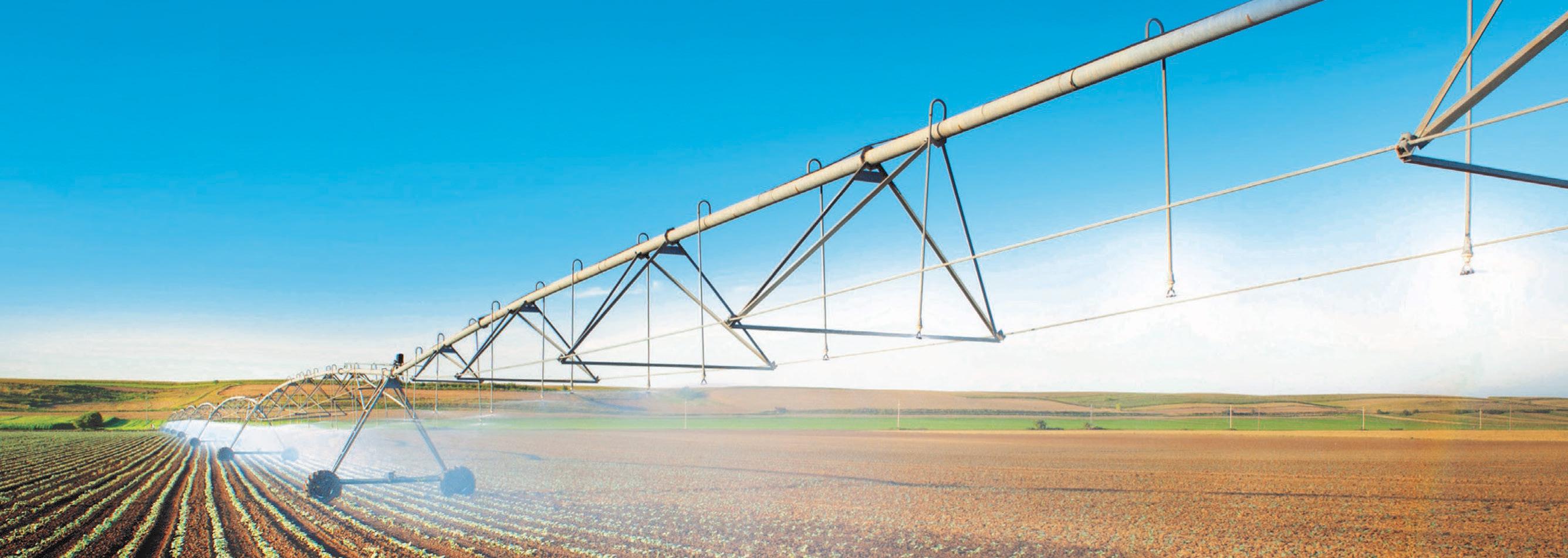
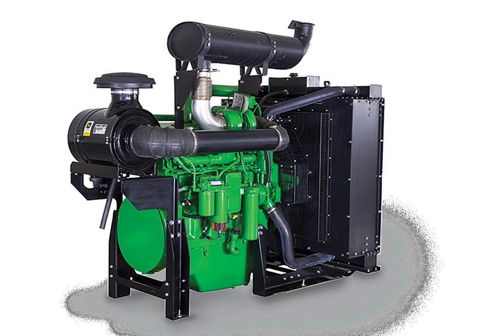


Completed capacity upgrade works, including a new aerator and installation of high-lift pumps, have revitalised the Ingham Depot Water Treatment Plant (WTP) as an evolving asset in local water security. We spoke to Hinchinbrook Shire Council to learn about the WTP upgrades, from procurement and the pump technologies utilised, to project completion and achieving community water security in the face of rain events.
Servicing the region surrounding Ingham in North Queensland, Hinchinbrook Shire Council has traditionally supplied potable water from two main sources: underground bores in the Como Road Toobanna area, and treated water from the nearby Herbert River.
Yet during times of heavy rainfall and flooding of the Herbert River, water quality emerged as an issue for both Council and the local community, due to the highly turbid nature of the river system.
Hinchinbrook Shire Council Mayor, Ramon Jayo, said, “When the water in the river is of poor quality, the pumping station is turned off and water is only drawn from bore systems around the shire.
Those bores have historically been inadequate to fully meet the Ingham and surrounding area’s water demands.”
A recently completed project to refurbish the Ingham Depot WTP has risen to the challenge of local water security and ensured a stable role for the Herbert River as a key water supply.
The major upgrade works of the project included new raw water delivery infrastructure, a new aerator and high-lift pumps, as well as the design and construction of new bores.
The project was taken on by Hinchinbrook Shire Council in a jointly funded project with the Queensland Government’s Building Our Regions (BoR) program, with Council receiving $2 million in funding from Round Three of the BoR program for a $4.4 million project that created 13 jobs.
Project beginnings: upgrade selection and procurement
Finding the right upgrade pathway
A review of systems uncovered three upgrade pathways for Hinchinbrook Shire Council to address the challenge of stable water access for the Ingham region.
The review allowed Hinchinbrook to:
• Investigate all the options to deliver a sustainable clean water supply including consideration of a suitable treatment system
• Assess the priority and affordability of options including a preliminary evaluation of the costs, risks and benefits including preliminary estimates for operations, maintenance and ongoing costs
The three upgrade pathways investigated by Council were:
• Option One: Implementation of a water filtration treatment plant for the Herbert River water source
• Option Two: Duplication of the Como Road Bore Field and Ingham Depot WTP augmentation
• Option Three: Development of bores near the Herbert River Intake Utilities Services Manager, Peter Martin, explained, “Capital and operational costs associated with Option One and Two were determined, which identified a similar capital cost on a dollar per megalitre basis.
"Ultimately, Council identified Option Two – Duplication of the Como Road Bore Field and Ingham Depot WTP augmentation – as the preferred upgrade pathway, noting its advantageous annual operational cost.
"As Hinchinbrook Shire is a smaller council, with staffing resources not always available to complete repairs, Council deliberately involved asset maintenance staff to confirm that the package of upgraded equipment could be affordably serviced and replaced.
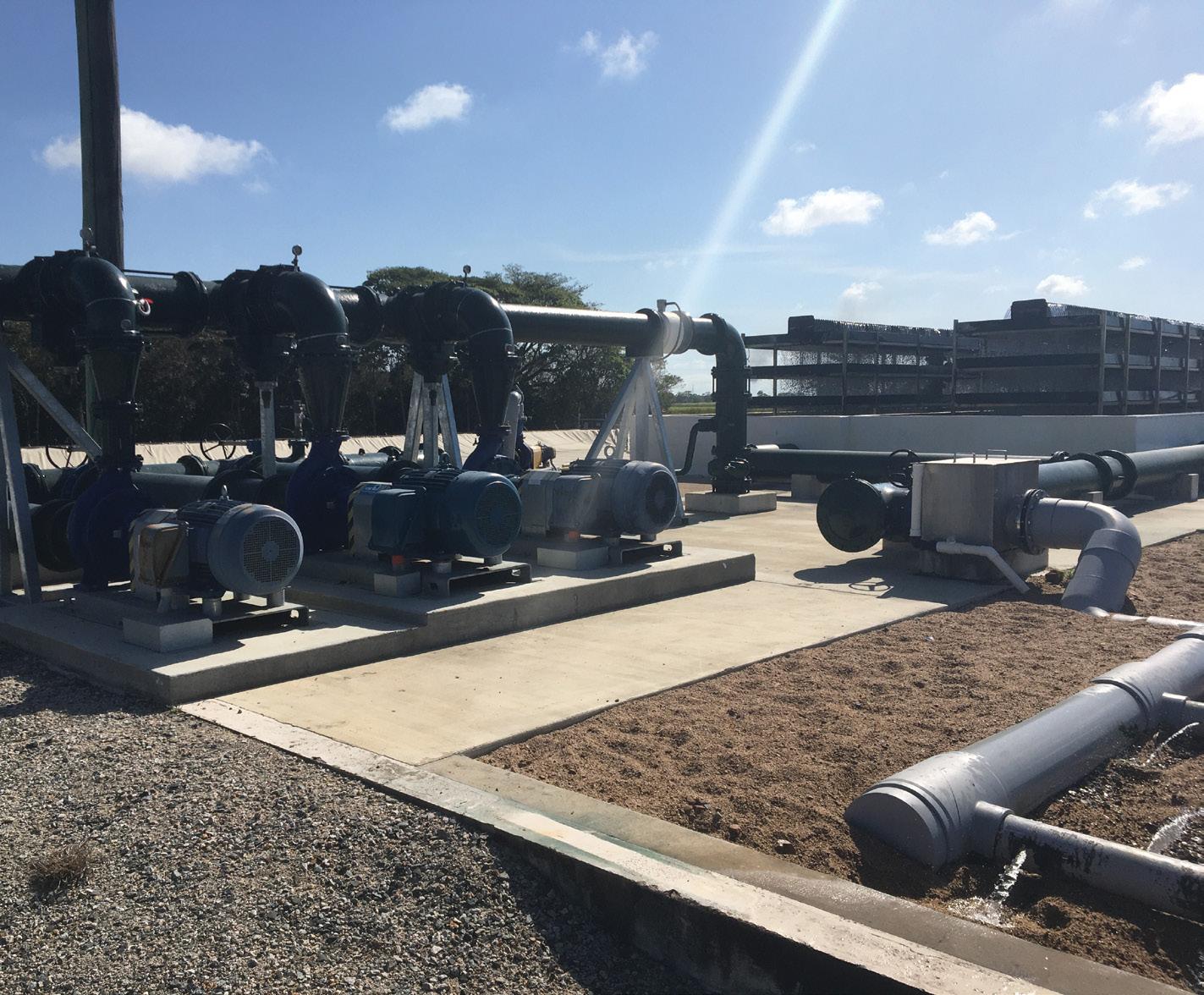
"As equipment was part of the whole tender package, the evaluation was reviewed by the Council staff that would need to maintain this equipment over its lifetime.
"Equipment was confirmed to ensure that they met design criteria, availability of spare parts and servicing, and regional service agents who could assist in the maintenance of these units in the future if required.”
procurement
The Ingham Water Plant upgrade project was tendered out as two packages: the Treatment Plant upgrade, and the installation of associated pipelines.
Peter Martin explained, “The treatment plant package included the supply and installation of new high-lift pumps –two 120L/sec pumps and one 60L/sec pump – as well as the supply of new bore pumps capable of delivering 60L/sec back to the treatment plant.
As this was a duplication process, the aerator was a copy of the existing one already on site.
Consulting engineers, GHD, completed the design and tender packages for the project, as well as provided project management.
Electrical and chemical dosing upgrades were also scoped as part of the Treatment Plant upgrade package.”
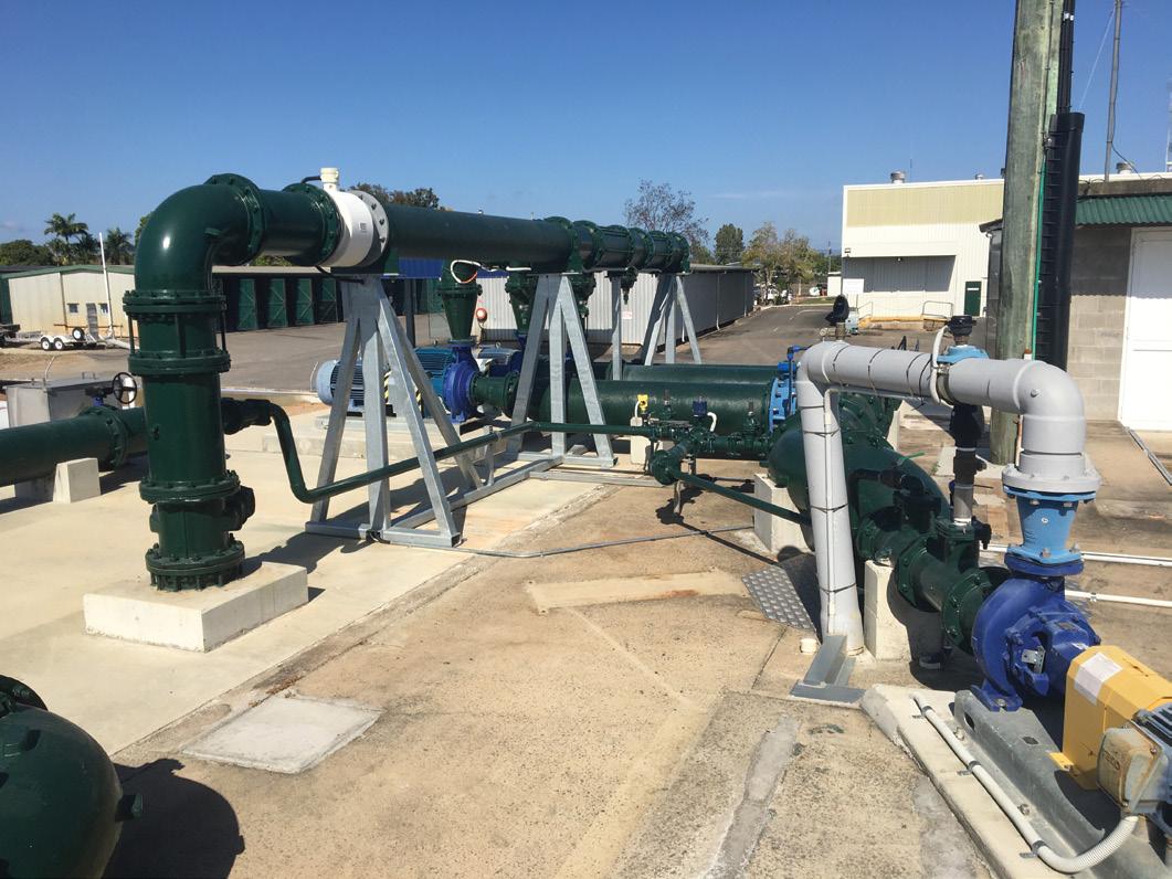
Project delivery: infrastructure, challenges, community impact
Key project infrastructure delivered The scope of process, civil, mechanical and structural work carried out under the Ingham WTP contract included the following:
• Fit out of a newly constructed water supply bore (construction of bore and casing to be completed by subcontractors) including modular submersible bore pump of 316 stainless steel (SS) construction complete with flexible riser, 316 SS safety cable, power supply cabling, level probe, integral nonreturn valve and break-off plug
• Upgrade of the WTP capacity, including DN250 DICL raw water supply pipework from new pipeline interfacing point at WTP
• Modification of the existing aerator sump to increase the height by 400mm
• New duplicate cascade aerator to match the existing aerator
• New pump out well and connection pipeline between the existing reservoir and new reservoir to allow for pumping out and/or isolation of a reservoir
• Three new pumps, including: single 60 litres/second (L/s) high-lift pump and two 120L/s variable speed drive (VSD) controlled high-lift pumps
• New recirculation pump (40L/s) to supply recirculation water to both aerators
• Supply, installation, testing, calibration and commissioning of new treated water sampling and dosing pump controllers
• Electrical switchboard, controls and telemetry elevated above flood level underneath a proprietary shade structure
• Connection to Ergon Energy power supply at adjacent power pole (provided by subcontractors)
• New inline concrete chemical dosing and distribution well
• New treated water storage lagoon with high density polyethylene (HDPE) liner and floating cover of approximate capacity of 1.5ML
• Replacement of floating liner on existing lagoon
• Upgrade of existing power supply (by Ergon Energy) and installation of new switchgear to suit Depot and WTP supply
• Replacement of existing WTP switchgear to suit the new WTP upgrades
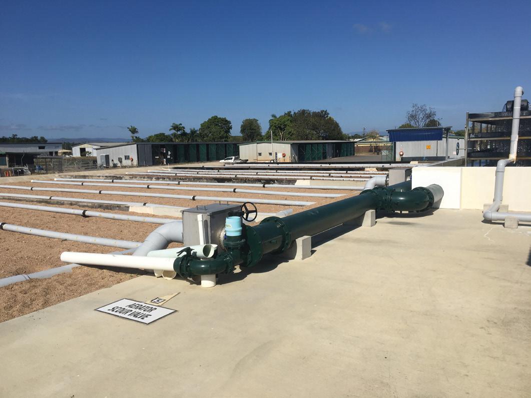
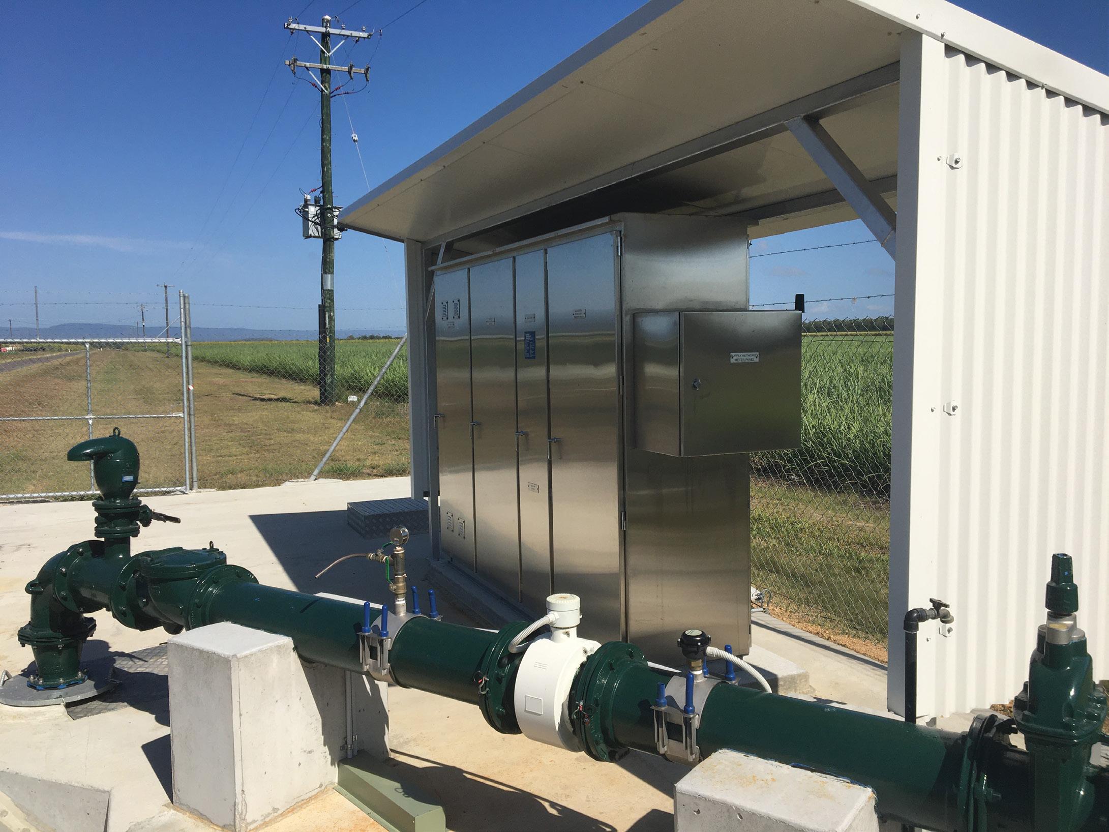
• Replacement of existing telemetry system with radio and Programmable Logic Controller (PLC) configuration for remote control of WTP
Success despite operational challenges
The success of the WTP upgrade project comes despite a central challenge of maintaining operation of the existing plant.
Mayor, Ramon Jayo, advised, “The major challenge with the WTP upgrade was that the existing plant had to be operational for as long as possible while construction of the majority of the new works were undertaken.
"The contractor’s schedule of works meant that a planned shutdown of the whole site was limited to only three or four days to allow for connections to existing tanks, pipelines and structures where the plant could not supply water to the system.”
The success of the upgrade despite operational challenges speaks to the dutiful design approach of the project’s consulting engineers, GHD.
“GHD’s design process incorporates relevant Safety in Design (SiD) processes, which will consider construction interface risk, including minimisation of changeover and commissioning of new infrastructure with existing, operational infrastructure.
"This design process involves the identification of key risks and adopting design principles to address such risk,” said Peter Martin.
Further challenges encountered on the Ingham WTP project included finalising permits for pipelines in the Main
Roads corridor, especially in finalising the design of the raw water pipeline crossing the main highway coming into Ingham. However, collaboration between GHD, contractors and the Main Roads team ensured a successful outcome.
Community sees success across security and capacity
Prior to refurbishment of the Ingham Depot Water Treatment Plant, flooding and run-off events that compromised the water quality of the nearby Herbert River would severely limit community water access to an inadequate network of bores.
The refurbished plant allows treated water from the Herbert River to play a more stable role in local water security, alongside the newly upgraded network of bores.
The upgrades will also deliver a boosted production capacity for the Ingham community.
Mayor, Ramon Jayo, informed that “Hinchinbrook Shire will have its potable water secured for the next 20 years with the construction of new bores and a raw water pipeline connecting to the existing network, to supply an additional 2.2ML/day to the Ingham Depot WTP.
"In combination with augmentation at the WTP, the total production capacity will reach 5.2ML/day.”
From selecting the best upgrade pathway and equipment, to working closely with the project’s consulting designers to ensure continued operation during construction, Hinchinbrook Shire Council has delivered a critical asset for water security in the local community, come rain or shine.
In processing raw sewage to high quality potable water, water treatment plants are exposed to erosion-corrosion, chemical attack and abrasion problems that result in increased operational costs.
Belzona® can provide a cost e ective solution to such maintenance problems by minimising downtime, labour and equipment replacement costs, whilst at the same time increasing the e ciency of the plant and ensuring environmental compliance in:
• Fluid handling equipment
• De-aerators, absorbers and process vessels
• Clarifiers
• Sludge de-watering
• Digesters
• Filtration
• Buildings & structures
• Mechanical damage to general equipment
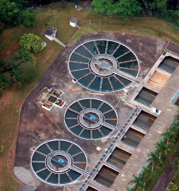
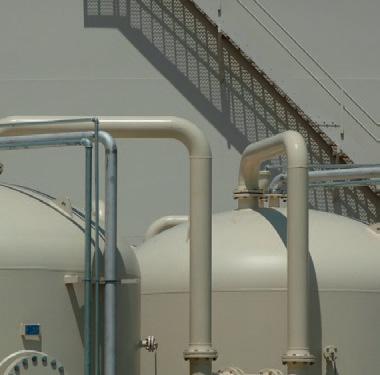
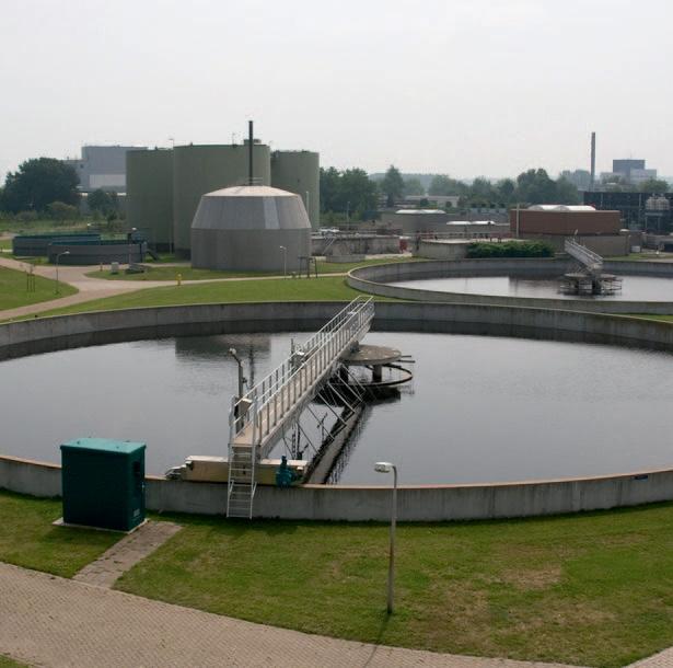
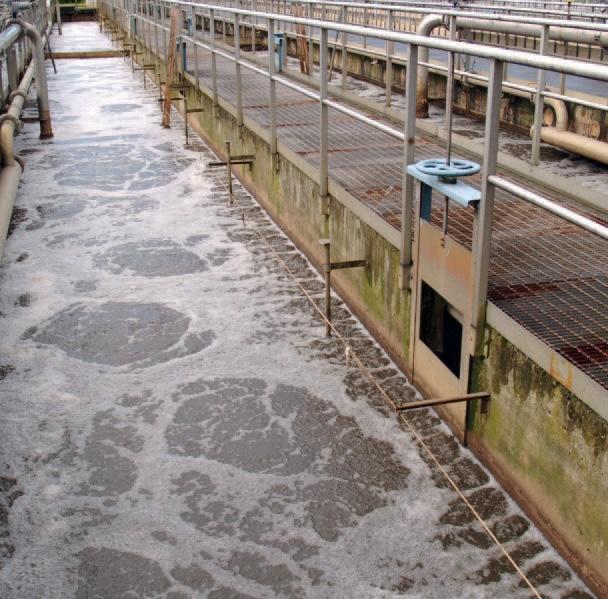
www.belzona.com
Belzona® provides the solution to your repair and maintenance needs.

Liquid Vacuum Pumps
•Rebuilding and protecting impellors and castings
•Auger and trough erosion protection
•Chutes and hoppers abrasion protection
Sedimentation Units
•Concrete repair and protection
•Sludge pump repair
•Expansion joints
Aeration Units
•Leaking pipes and nozzles
•Eroded fans and blowers
Chemical Treatment
•Tank lining
•Pump protection
Sludge Treatment
•Sludge pumps
•Dewatering units
•Hopper abrasion protection
Methane System
•Corrosion to scrubber vessel
•Leaking gas and water piping
•Erosion-corrosion in gas compressors
Fluid Handling Equipment
•Maintain pump e ciency
•Improve pump performance
•Repair and protect leaking pipes
•Flange face protection
•Repair and protection of valves
Water Treatment
•Deteriorated filters and strainers
•Chemical containment areas
For further detailed information refer to:
Belzona® Product Specification
Belzona® Instructions For Use
Belzona® KNOW-HOWIn Action
Contact Us: Head Office: 03 8720 8600
Nth QLD - Michael Christian – 0477 003 410
Sth East, Central QLD and PNG - Andrew Petroff – 0425 863 004
NSW - Beau Dowton – 0427 070 252
VIC, TAS & NT - Trevor Comb – 0433 946 337
SA - Charlie Farrant – 0409 780 775
WA - Michael Dutton – 0430 294 334
Through a global distribution network covering 120 countries, Belzona® can provide a full 24 hour on-site service with guidance and technical advice on the application of Belzona® products, available through the local Belzona® Consultant.
Since 1952 Belzona® has provided global expertise in the development and manufacture of innovative repair and protection solutions. Across a range of industries Belzona’s track record has gained the confidence of countless engineers, contractors and maintenance personnel throughout the world.
Industry can count on Belzona® to provide a prompt response, whether it is an emergency repair or simply a routine maintenance issue.
Belzona® products are engineered to withstand the most aggressive environments such as erosion, corrosion, abrasion, chemical attack and mechanical damage, extending equipment life and improving e ciency.
From the chemists and engineers in the Belzona® centres, to the network of local Technical Consultants, each person is part of the Belzona® team, knowledgeable and trained in solving the problems of your specific industry.

is
Before arriving at the industries, to ensure the excellence and reliability of each supply, every WEG electric motor undergoes rigorous quality testing according to the main international standards. Continuously investing in innovation and technology, WEG has developed an application to provide customers and users with access to technical documents, such as data sheets, performance curves, technical drawings, nameplates, and results of electrical testing performed on motors, reinforcing the transparency of our processes.
Recognised for its excellence in energy efficiency for various applications, WEG offers the market numerous high performance solutions to bring more innovation, technology and reliability to industrial processes worldwide. WEG
Where is WEG Data Viewer available?
Available for Android and iOS platforms, WEG Data Viewer can be accessed by anyone who wants more information about every motor that leaves WEG factories.
How does WEG Data Viewer work?
By means of a QR code, provided on a label attached to the fan cover, shaft end or the inside of the terminal box, it is possible to obtain, at any time, the motor technical information. For motors without the QR code, it is possible to access the information by entering the serial number available on the nameplate. Everything you want to know about your WEG motor is at your fingertips.
Technology that guarantees greater reliability
According to Rodrigo Fumo, Director of Engineering and Technological Innovation at WEG, “WEG Data Viewer was designed to simplify routines, comparative analyses and maintenance, since it provides quick and easy access to key product information. It is an application that all WEG customers can use.”
In future updates, the application will gather other motor technical information, such as operation and installation manual, catalogues and dimension testing reports. Thus, WEG will guarantee the digital supply of its technical documentation.
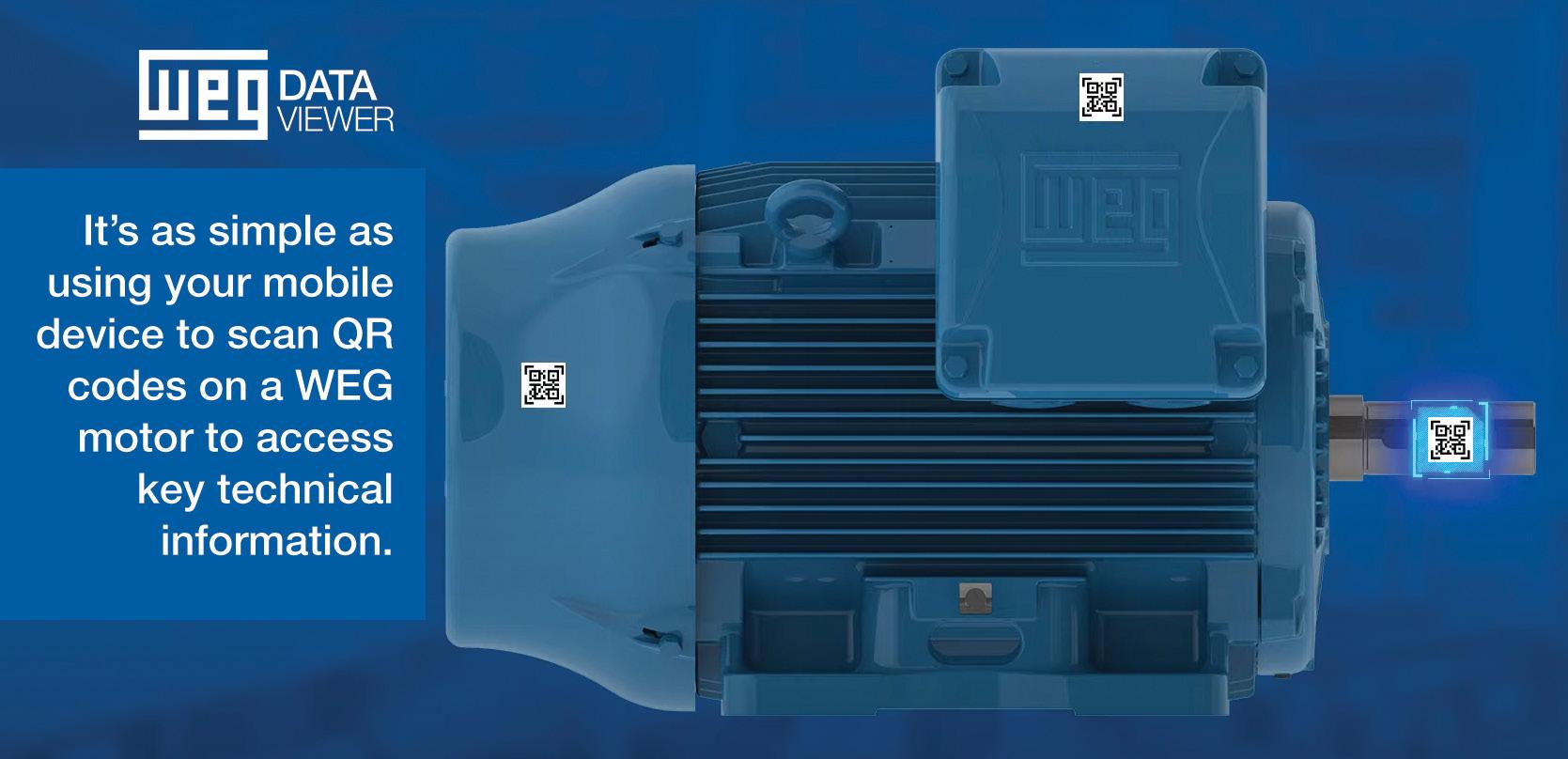


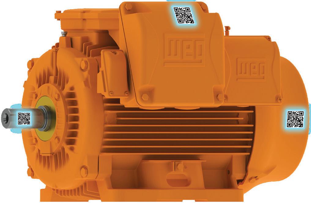

When a water treatment plant is decades older than the local government area that it services, it is bound to experience some aches and pains that result in a lower drinking water quality. This was the case for Forbes Shire Council’s water treatment plant, with equipment reaching the end of useful life or not working as efficiently, and continual breakdowns requiring maintenance. To rectify these issues and ensure the plant can continue to produce high-quality drinking water for decades to come, Council undertook an upgrade to Plant A and Plant B.
The Forbes Water Filtration Plant, which is situated on the Lachlan River, is a conventional filtration plant comprising two trains (Plant A and Plant B) which have their own mixing tank, flocculation and clarifier tanks. Combined, the plants have the ability to deliver 26.5ML per day.
Upgrades of Plant A and Plant B began in 2019 to bring them in line with the highest modern efficiency and monitoring standards required to meet the needs of the community and NSW Health legislation.
Forbes Shire Council Project Officer (Water), Andrew Quirk, said that the upgrades needed to be made for the continued operation of the water treatment plant.
“All these upgrades and replacements were needed as our plant had all but reached its useful life age with multiple issues starting to arise – the main issue being the filters not performing consistently,” Mr Quirk said.
“With Plant B first constructed in 1946, and Plant A built in the 1960s, we were experiencing continual breakdowns, which led to us not always meeting drinking water health guidelines.”
Other initial issues in Plant A included the failure of a filter. The filter had an old underdrain system, where the pipe had rusted through and filter media was lost through the filter, moving through to the cellar tank.
As the filter had been coated in a black epoxy, there was no visual reference for when it would be back in service. The filter had been out of service for a number of years, as the other nine filters could pick up the extra filtration needs.
During the planning of the refurbishment of this filter, another filter presented with the same underdrain issue. This resulted in the decision to replace all filters in Plant A with new coatings. This decision was to proactively upgrade the filters, rather than waiting for each of the filters to fail, potentially causing catastrophic consequences for the community’s drinking water supply.
What did the upgrades involve?
Water to both plants
Prior to the upgrades, only water from the Lachlan River could be treated in both plants, and bore water could only be treated through Plant B, due to the inlet configuration. The recent upgrades and modifications to the inlet pipework enable bore water to be treated through both plants.
Upgrades to Plant A began in 2019, when one of the filters was rebuilt. Since then, all ten filters have been reconstructed with the extra capability for constant online turbidity monitoring of each filter.
A new concrete coating for all filters was part of the upgrades, in order to protect the integrity of the concrete filler bays and provide an extended life expectancy for at least 30 years.
Intercrete was chosen as the Five Part Coating System for the solution, and Sydney’s Mattioli Bros applied the coating, which will allow for annual high pressure wash cleaning for filter maintenance.
In 2021 the Plant A filters were also refurbished. This work followed a similar process to the Plant B works, however it also included the removal and replacement of the Filter roof. The old roof, containing asbestos, was removed to allow for the launders and underdrains removal and a new, larger roof was installed. The new roof now covers both A and B plant filters and contains new LED lighting to enable operators to clearly see water quality.
Murray Engineering was engaged via tender to supply and upgrade three high lift potable water supply pumps to feed the town’s reservoir from the treatment plant. The existing technology was installed around 1978 and was well past its
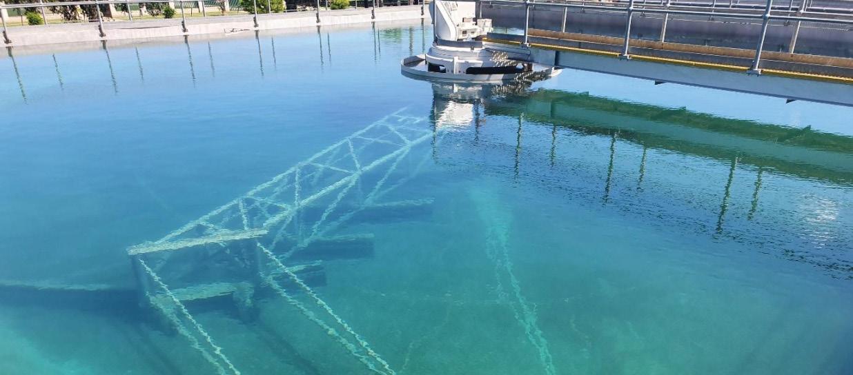
lifespan. With the new pumps, Council has future-proofed its system for at least 50 years and will be able to realise power savings. A fourth pump – a dual discharge headed pump manufactured by DynaPumps – was also installed as a smaller capacity pump to the three high lift pumps to further futureproof the system, as well as to give Council a way of wasting the water from the clear water well if there was a quality issue which required the well to be pumped out.
Installation of variable speed drives, and new pump motors are further making the plant more energy efficient and allow staff to optimise operations.
Alchlor dosing pumps
New dosing pumps were also installed to replace the existing aluminum chlorohydrate (Alchlor) dosing pumps. The existing metering pumps were overrated for the dosing of aluminum chlorohydrate, when the plant was operating on bore water. Due to the low turbidity of the bore water, Alchlor dose rates of only 5-8mg/L were needed, which was impossible for the existing pumps to achieve. The new pumps are VSD-driven and can operate at a variety of flows, significantly improving operability of the system. Potassium permanganate, to manage iron and manganese dosing, was also introduced to the process.
Three peristaltic hose pumps – two duty pumps and one standby – were chosen to replace the existing oversized Alchlor pumps. Online flow meters were also installed for verification of drop tests, as well as to provide live online monitoring of dose rates through Council’s SCADA system; the flow meters and VSDs are connected to SCADA to enable alarms and plant shutdown in the event of a pump failure.
In addition to the work on Plant B, works were also undertaken on the Plant A including:
• Installing five new steel underdrain filtration systems complete with new media
• New schedule 80 air pipework to repair leaks
• 13 new hatch NTU units for Plants A and B
• Air matrixes in Plants A and B for process control
• Online ATI instrumentation for CL2 and pH monitoring at reservoirs
• New 304 grade steel clarifier total rebuild
• Plant B clarifier tank total recoating and dynamic/static crack repairs
• Plant B flocculation tank total recoating
• Plant B flocculation paddles speed adjustment and direction change
• Procurement and installation of a new Atlas Copco air blower
• Telemetry upgrade from Radtel to ClearSCADA throughout the entire water and sewer network
• All pneumatic filter control valves replaced with new valves and actuators
Planning process
The upgrades to the water treatment plant had to be timed and planned carefully to ensure that there was as little disruption to the community as possible.
Mr Quirk said that the planning process for the upgrades was initially reactive, as the plant responded to constant plant failures.
“Once we had got on top of the main issues, we made a priority list. From this list we used in-house staff and external contractors to achieve results,” Mr Quirk said.
“We never really considered total plant replacement, as the bones of the plant are in relatively good shape, and the cost of replacement of a plant this size would run well into the tens of millions, with our in-house upgrade costing a fraction of this.
“There were a few considerations to be made whilst the upgrade was conducted, but minimal impact to supply was encountered, due to the nature of the plant’s setup.
“With both plants separated, we could run on one plant whilst the other was worked on. Most works were also conducted during the winter months, when consumption was low, to negate any possible interruption to supply.”
Procurement process and factors involved
Forbes Shire Council sought three quotes for all items over $5,000, in line with local government processes.
“For larger items (pumps, stainless steel underdrains, replacement of Plant B sludge rake) and works, we either went out to market for a request for quotation, or followed the tender process,” Mr Quirk said.
“During the upgrade, to make our procurement process a little easier, we went to tender for preferred mechanical and electrical services with two local contractors securing the contracts.
“Under this contract, Council can engage the contractors without following the three quote system for services making planned and unplanned works much easier.”
When it came to pump supply, valves and electrical supplies, Council’s water management team researched the different options before selecting products or suppliers.

“Items were considered for reliability, availability and price,” Mr Quirk said.
“We used industry knowledge and contacts in some instances to help make our decisions easier.
“The main factors for us that we considered in selection of equipment were reliability, meeting our specified scope and availability.
“Most items we went to market with were relatively similar in price so this was never a major selection factor. Most of the time with our selection of pumps it was almost swapping out like-for-like specifications with what was originally installed with a few exceptions.”
With the plant not only looking to maintain efficiency but also to improve it, a new online monitoring system was installed which could detect faults more quickly.
The system monitors all ten filters continuously reporting on turbidity, settled water turbidity and raw water turbidity. It also monitors finished water at the start of the clear water well and on the discharge of the high lift pump, which feeds into four reservoirs and a reticulation system.
The filter turbidity units that were installed are Hach TU5300sc with auto cleaners, and the raw water analyser is a Chemitec surface scatter style. With online chlorine residual and pH monitoring at both locations on the clear water well, the system has proven to be highly reliable.
“The new monitoring has proven on a number of occasions to be a highly effective early warning sign when something has failed within the process,” Mr Quirk said.
“We have been able to rectify problems within the process well before they become a larger water quality issue, ensuring we continually meet drinking water guidelines.”
Mr Quirk said that in-house operations proved extremely successful, and noted their potential use in future projects.
“One of the biggest lessons we learnt from the initial Plant A works was that we could complete the proposed future works in-house, using mainly council staff and local contractors,” Mr Quirk said.
“We also learned that the new filter system was very reliable, which gave us confidence to use the same Triton underdrain system in the B plant.”
However, crews ran into challenges when it came to some aspects of the Plant B upgrade.
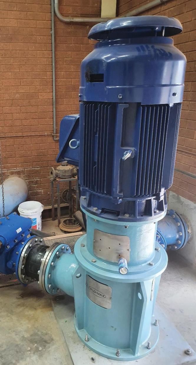
“The biggest obstacle we found during the work phase was getting the new Plant B sludge rake to perform at the same level as the old rake,” Mr Quirk said.
Plant’s new fourth high-lift pump with dual discharge head.
“We also encountered hold ups with the rake install which delayed this phase of the project from being completed in August to November.
“It was a stressful period, with the summer months nearing and the need to bring Plant B back online due to increased consumption, we engaged a Sydney-based contractor to rectify the issue that was stalling the completion.
“We narrowly finished this phase before summer consumption increased with the rake performing at a better standard than the old.”
The upgrades have resulted in better optimisation of the water treatment plant, and a new system for continuous data monitoring, which will detect issues early and ensure Council is able to consistently provide high-quality water that will meet the Drinking Water Guidelines into the future.
“The upgrades have optimised our control of the system, with better data being collected through our online monitoring, and with data taken to weekly team meetings for review by the management team for operations to be further enhanced,” Mr Quirk said.
“It has also been highly beneficial to our plant operators, giving them a better understanding of the plant's process and its functions.”
Not only have the completed works increased efficiency and reduced plant failures, but the ripple effects of the upgrades means that Council will be able to consistently meet water targets.
“The upgrades have given Council greater flexibility in utilising either of our two raw water sources – river and bore waters,” Mr Quirk said.
“It has enabled us to continually meet our water chemistry targets, the main one being the ability to continually supply treated water at under 0.1NTU, which before the upgrade was never the case.”
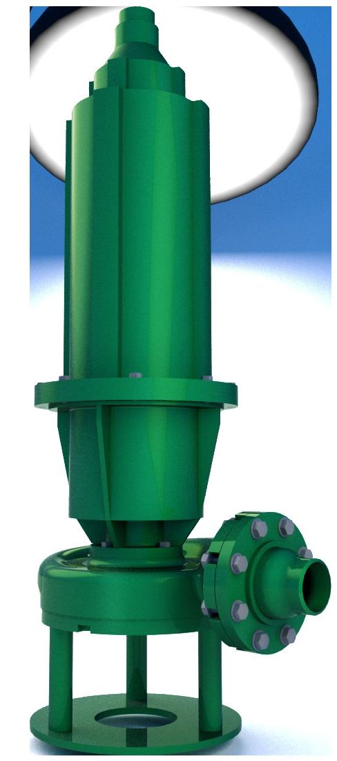



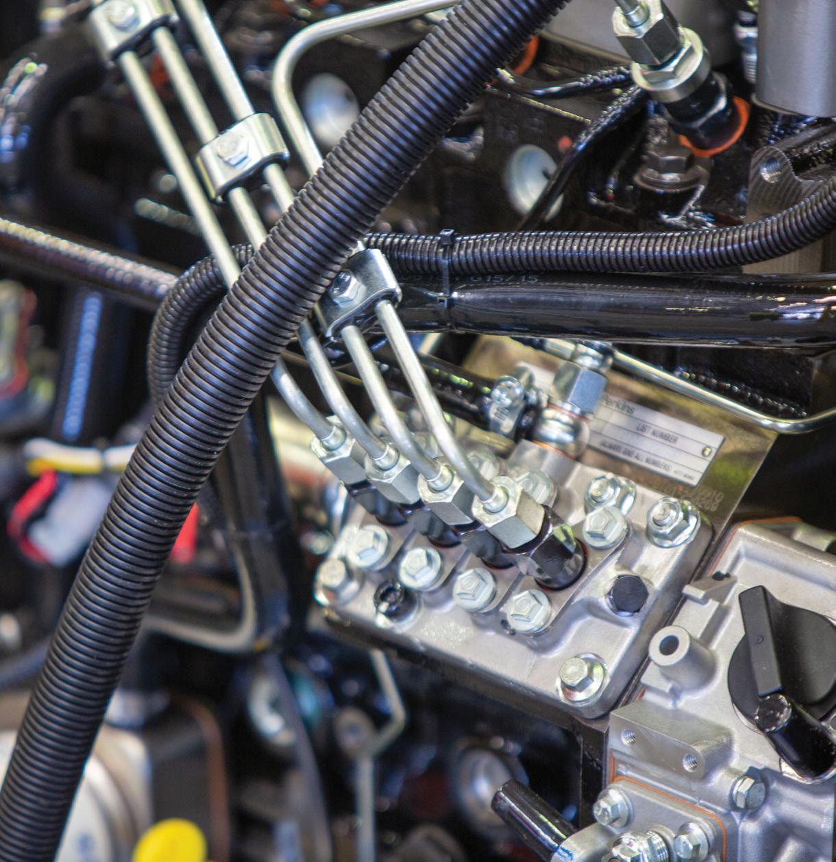
Just like owning a diesel car, light towers, pumps and generators will require regular engine maintenance. The general rule for servicing your new equipment is critical and/ or weekly use requires a monthly service schedule whilst non-critical and/or use once a month requires a quarterly service schedule.
AllightSykes can provide a service schedule for you that covers the usage and application requirements of your equipment to ensure it is safe, ready for use and maintains its value. Some equipment will require more frequent servicing depending on load and climate.
Unplanned, reactive maintenance has many overhead costs that can be avoided during the planning process. The cost of unplanned maintenance includes lost production, higher costs for parts and shipping, as well as time lost responding to emergencies and diagnosing faults while the equipment is not working. Unplanned maintenance typically costs three to nine times more than planned maintenance.
With a maintenance plan, reducing the overall cost of equipment is simple. Equipment can be shut down to coincide with production downtime. Prior to the shutdown, any required parts, supplies and personnel can be gathered to minimise the time taken for a repair. These proactive maintenance measures decrease the total cost of maintenance activities.


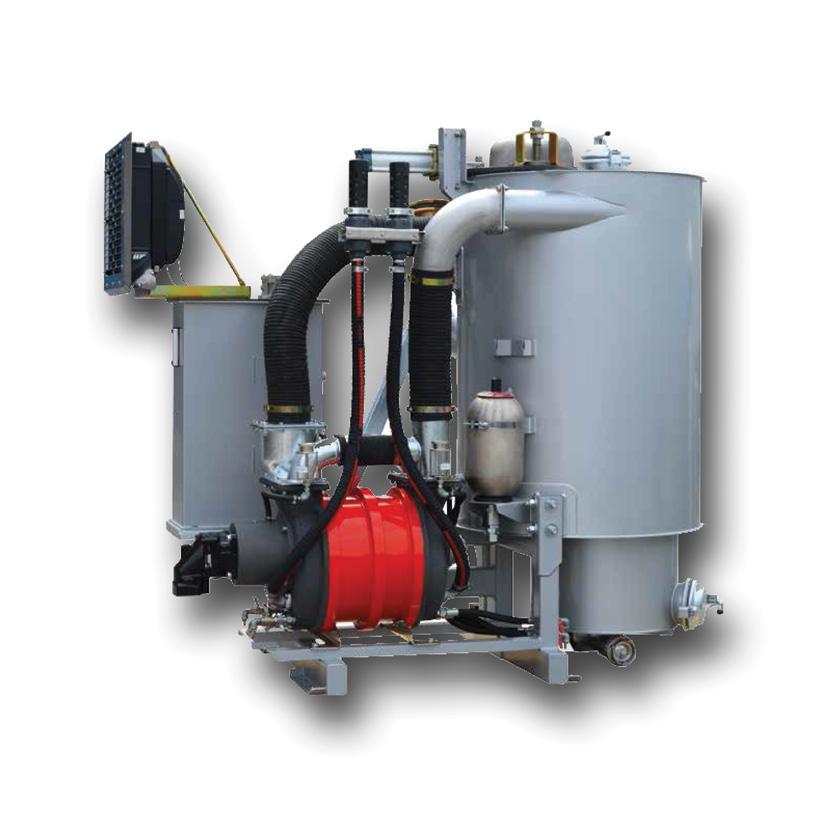
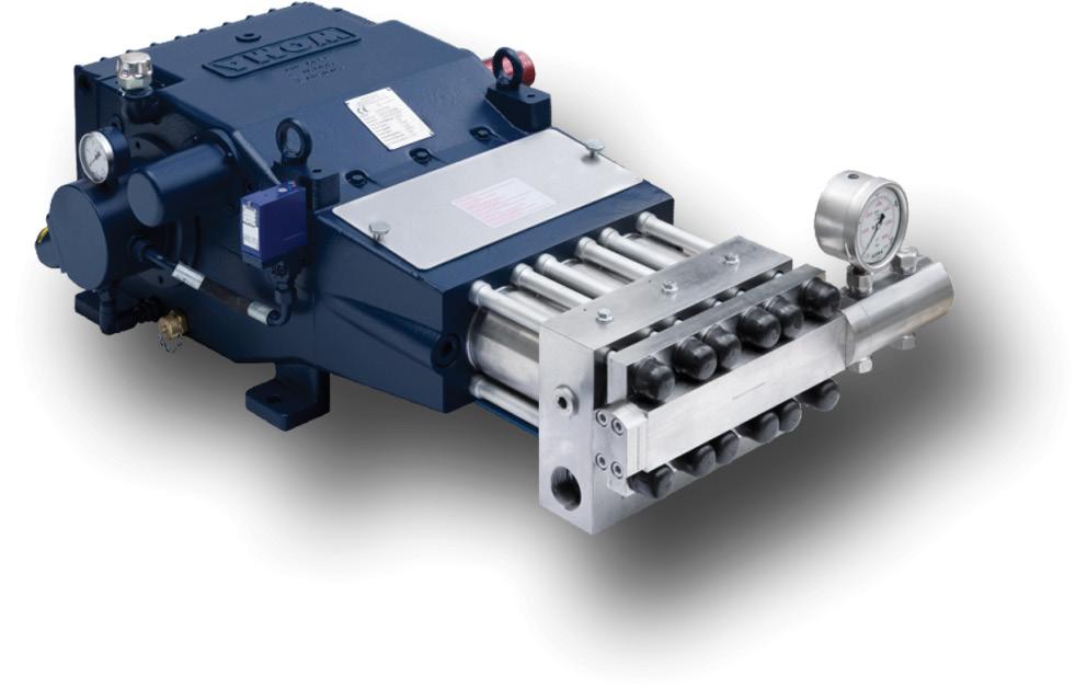
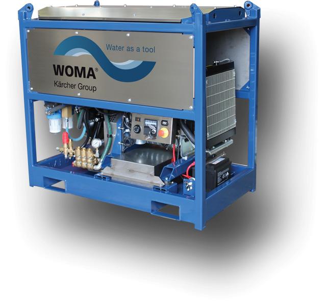
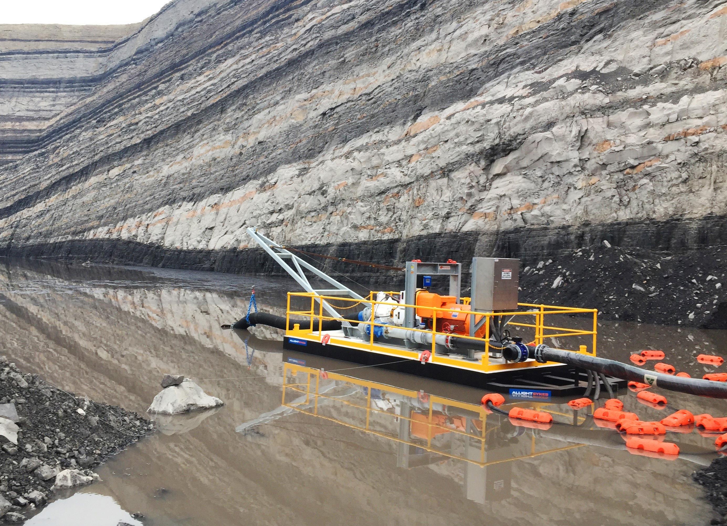
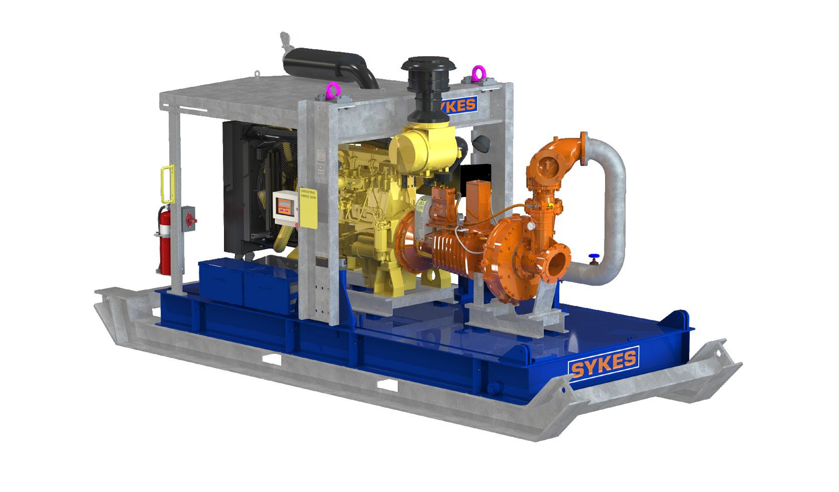
High Head pumps are the water management solution of choice in many of the world’s harshest mining and construction environments.
Boasting one of the best shaft stiffness ratios of any automatic priming pump on the market, the Sykes High Head range provides the reliability and toughness to meet market expectations.
Contact our team for more information on our extensive range of Dewatering Pumps, Mobile Lighting Towers and Generators.

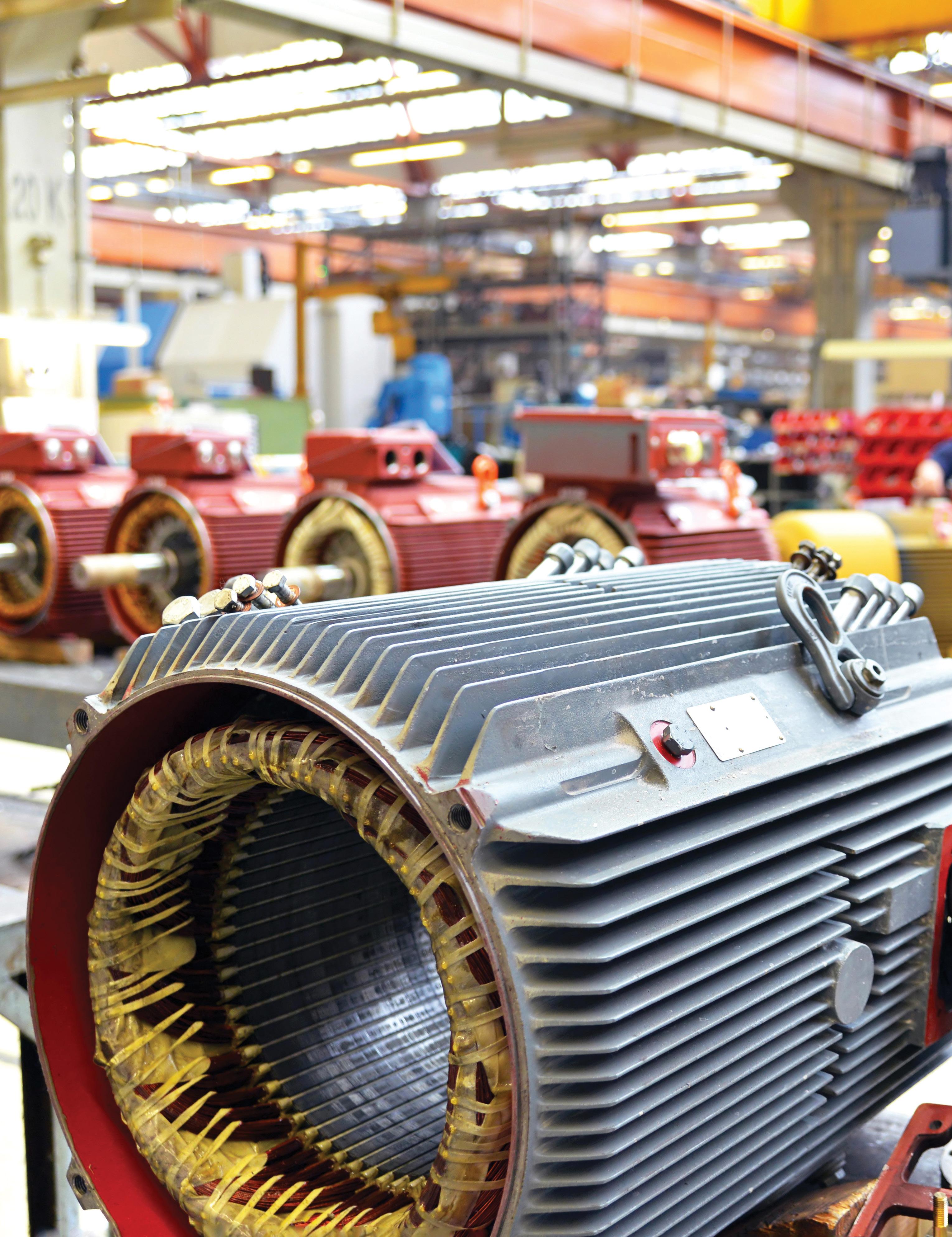
Karl Metcalfe, technical support at the Association of Electrical & Mechanical Trades (AEMT), has provided advice on the correct management and regular servicing required to store electric motors.
Stored motors that are operation-ready are essential in the event of a motor failure, and the correct storage can ensure they are properly maintained and ready when required.
Most commercial and industrial operations will rely on electric motors and for many organisations it is standard practice to store working spares so that, in the event of a motor failure, downtimes can be minimised by swapping out the failed motor with a working spare.
Firstly, it is important to keep stored motors protected from vibration and extremes of temperature and weather, so outdoor storage is not advisable. Ideally, electric motors should be stored indoors in a clean and dry environment.
While a climate-controlled environment is the best option for storing electric motors, in some instances, this may not be possible. In such cases, the motor may need to be palletised outdoors.
If this is the only option, the motor should be covered loosely with a waterproof covering, ensuring that air can circulate to help minimise condensation. It is also important to try and protect lower IP motors from pest intrusion.
Ensure that all openings – cable entries, air vents, grease pipes etc. – are suitably covered or sealed during storage.
Exposed surface areas could also be coated with a corrosion inhibitor which will need to be removed before the motor goes back into service.
Protecting bearings
To protect from vibration indoors, it is also a good idea to store motors in locations that are not near any ambient vibration areas.
Bearings in stored motors have been known to fail due to fretting or false brinelling as a result of environmental vibrations, which induces small-scale motion of the bearings. Even minimal ambient vibration will cause motor bearings to wear over time. Storing motors on materials that can help absorb vibration is, therefore, good practice.
Regular shaft rotation also helps to reduce bearing wear on any one point of the bearings, helping to prolong their life. The Association of Electrical and Mechanical Trades advises that shafts are rotated at least once a month, with the shafts of larger motors turned more often.
While it is generally acknowledged that shaft turning is necessary on stored equipment, AEMT members have reported that, in practice, the task is rarely actioned often enough. So regular shaft rotation should be made someone’s responsibility, as part of a store’s maintenance schedule.
Ensuring adequate lubrication
For grease-lubricated motors, the shelf life of the grease in the bearings should be a consideration. If the motor employs sealed bearings, it is very likely that if not in operation for an extended period – say two years – the grease inside the bearing will separate and will not work optimally when required to start turning again.
Motors that utilise regreaseable bearings should be regreased on average every year or so when in storage, to help prolong bearing life and ensure that the motor is fit for service when needed.
Any moisture or dampness in the air will eventually find its way into a motor and speed up the oil oxidation process. So, as
well as minimising corrosion, a dry environment is advisable for storing motors to prolong the effective life of their lubrication.
The AEMT advises that before putting an oil-lubricated motor into storage, it is a good idea to first drain the oil, flush it through and replace it with fresh oil. In operational motors, the oil helps ensure that any debris or particles are held in suspension while the motor is running.
But, when stationary, the debris held by the oil will sink to the bottom of the motor sump. Then, when the motor is finally started up again, all the debris will be quickly pulled through the motor.
Ensuring that stored motors are filled with the correct quantity of clean oil, and making sure that it is sealed correctly, will slow down the inevitable oil oxidisation process.
In reality, however, all stored motors will be subject to some degree of temperature fluctuation, and this will cause the seals to expand and contract, allowing moisture to enter the motor.
Because the oil in a stored motor will degrade over time, it is advisable, as part of the maintenance schedule, to regularly check the oil in stored motors, and it is good practice to change the oil before starting a motor after a long period of inactivity.
Before putting a motor into storage, it is also advisable to perform an insulation resistance (IR) test, which measures the total resistance between any two points separated by electrical insulation. This test determines how effective the insulation is in resisting the flow of electrical current.
Before putting a motor back into service, repeat this test to ensure that any decreases in insulation effectiveness that may have occurred during storage can be addressed.
After installation, vibration levels should be recorded to evaluate the spectra on motors with rolling element bearings for any signs of bearing fault frequencies. A vibration analysis should be performed during start-up with uncoupled baseline vibration levels documented.
AEMT members have frequently reported stored motors being used as a source of unofficial spares for operational motors – most often, they are found to be missing parts such as terminal box lids and fan cowls.
This practise should be discouraged. While it is often only the intention to ‘borrow’ a part, too often, the part does not get replaced, which means that the spare motor will not be operation ready.
If this absolutely has to happen, it should be recorded in a spares inventory or similar, and the implications of not having the donor motor available as a spare assessed.
Minimising downtime is critical in many sectors, with the cost of interrupted production or operations often having significant bottom-line implications.
Therefore, being able to quickly and effectively respond to issues with plants and equipment is essential.
If kept in the right environment and properly maintained, motors can be safely stored for many years without encountering any problems when they are put back into service. But to ensure this is the case, AEMT indicates a planned approach to motor storage is crucial.
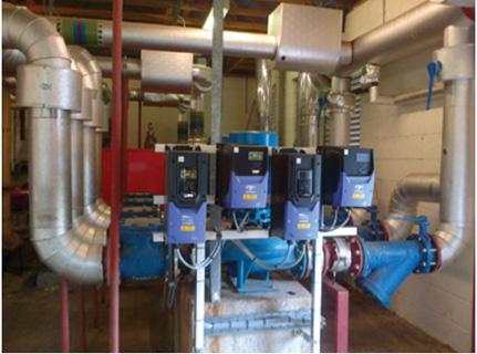
TWith energy costs continually increasing, it is more important than ever to keep track of energy usage and to implement efficiency solutions in areas of high-power consumption. Pumping systems account for nearly 20 per cent of the world’s electrical energy demand. In some industrial applications, pumping consumes between 25 to 50 per cent electricity. More than 85 per cent of this energy is wasted by oversized pumps and lack of control or non-efficient control.
echtop has partnered with Invertek Drives out of the UK who has developed a dedicated pump control technology that pays for itself.
Improve operations and reduce costs
Optidrive Eco can significantly reduce energy consumption, total system cost, simplify systems by eliminating complex control panels, and greatly improve process control and system reliability.
The system provides consistent, matched and pressurised water flow on demand by taking care of your equipment thanks to built-in protection including dry run protection, pump prime, burst pipe protection, load monitoring, blockage detection and pump alternation.
Optidrive Eco variable frequency drives offer solutions for a wide range of pumping applications and are ideal for standalone multi-pump booster systems which can be adapted to different requirements.
Optidrive Eco has a built-in Optiflow controller that is energy efficient, provides low harmonics, and is suitable for self-redundant multiple pump cascade controllers. This provides an ideal solution for water pressure booster systems widely used in all pumping applications.
Designed for durability and ease of use
Designed to be easy to use, with a user-friendly interface and simple to commission, Optidrive Eco exists in three different enclosure types: cabinet mounted IP20, wall mounted IP55 or IP66 outdoor rated.
A few examples in proven water applications:
• 36 per cent reduction in energy and reduced downtime on a high-powered water pump at a large water treatment plant
• 30 per cent energy saving at a major multi-story shopping centre
• Reduction in water and energy usage through the control of an irrigation system at an 18-hole golf course
• Securing a constant and reliable water supply with energy and cost savings at a major hospital in the middle east
• A constant and reliable water supply to a ten-storey apartment block controlling 4kW pumps
The product is rated to operate in ambient conditions from -100C to +500C and has optional Bluetooth connectivity; simply use your smartphone or PC to wirelessly commission or check your drive.
Optidrive Eco has a useful motor preheat function to help ensure moisture is not permitted to collect in the motor during periods of inactivity and prior to motor start up.
The Techtop story so far, founded by well-respected directors Rohan Pollard and Jeff Aird, entered a joint venture partnership in 2013 with Shanghai Top Motor company, the largest manufacturer of aluminum motors in China.
The combination of partnering with a leading global motor manufacturer and having Australia’s most experienced sales and engineering teams has seen the business grow to having warehouses and workshops in all states of Australia and a key partner in New Zealand.
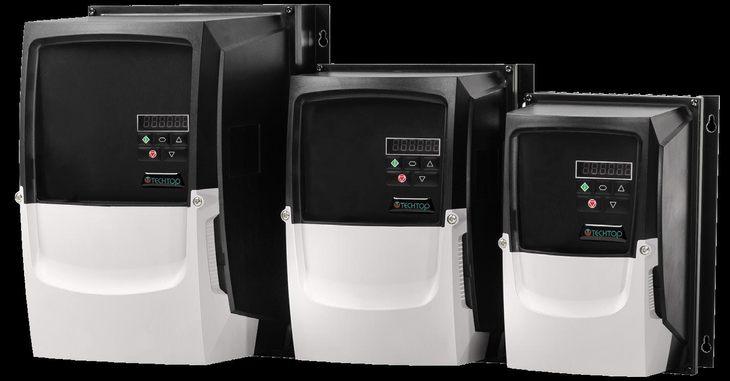
If you require further information or advice, you can contact our office on our toll free number 1300 832 486 or www.techtop.com.au










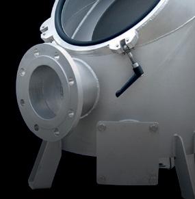


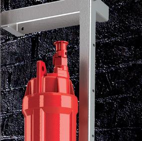




In everything we do, we never lose sight of what is more important to our customers: to work economically with a technology that is modern, innovative and reliable.
As the inventor of the elastomer-coated rotary lobe pump and innovation driver in the field of pumping, grinding and disintegration technology, Vogelsang has been one of the world’s leading mechanical engineering companies for decades. With progressive concepts and sophisticated technology, such as the RotaCut macerator or the wastewater twinshaft grinder XRipper, we work daily on efficient solutions for the individual applications of our customers.
We use our extensive know-how, the continuous further development of our technical solutions and our many years of experience in the field of environmental technology to support our customers as a competent partner. Among other things, with powerful and service-friendly technology. You can rely on competent and personal advice and reliable service.
Unit 2/7 Dunn Road | Smeaton Grange NSW 2567 | Australia
Phone: +61 2 4647 8511 | E-mail: sales.au@vogelsang.info vogelsang.info




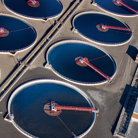




When it comes to pump drive selection, poor decision-making can result in overloaded motors, cost inefficiencies and a unit life that is drastically cut short. Here, Pump Industry uncovers the common mistakes and key factors to consider when choosing a pump drive that is right for your application.
Pump drive selection can be a confusing and complicated process, with many industry professionals leaving the decision-making in the hands of pump selection software.
While software can be a helpful tool, understanding the factors that influence pump drive selection will help to make a more informed choice, and will ultimately lead to a more durable, cost-effective and efficient solution.
Pump drives provide the essential function of connecting a pump to an input rotational source, such as a motor or engine. The pump drive might entail a motor, an inverter or a gearbox that can moderate motor speed.
A pump drive can be selected after the pumps have been properly sized and chosen, and the type of engine has been decided upon. Once these elements have been defined, the next step is to find which pump drive is most suitable for the application. It is helpful to choose the pump drive before plans and blueprints are drawn up.
If the selected pump is too big, money could be wasted in the initial cost of the unit. On the other hand, if the pump is too small, it will reduce the life of the motor and increase the chance that it will overload and fail the insulation system.
To have the best chance of an efficient and long-lasting pump drive, here are seven considerations which could impact your selection.
Each project will require a varying number and types of pump, depending on the needs of the project, the medium that is being pumped and the pump specifications.
This will impact the amount of power that is needed to operate the application and ensure the pump will consistently meet the requirements for sustained operations.
The pad number determines how many pumps are mountable to a drive, which in turn will impact the type of drive that should be selected. The pump drive should be able to accommodate the necessary number of pumps for the application.
These considerations are extremely important – without a suitable selection, pumps may be stressed past operating limits, eventually resulting in failure of the system.
The size of the drive will differ depending on whether a diesel engine or electric motor is being used. Sizing calculations are often determined by computer programs or graphs, as electric motors develop a very high starting torque, whereas the starting torque for diesel and gas engines remains relatively consistent.
The size of a hydraulic power unit should be based on torque, speed and power requirements. Since the cost of electricity needed to operate an electric motor over its lifespan is far greater than the cost of the motor itself, correct sizing of a power unit can save a significant amount of money in the long term.
Calculating the horsepower rating is important for determining the torque of the driver, and will influence a range of other factors when deciding on the appropriate pump drive. Horsepower can be calculated with specific computer programs or graphs. An excessive RPM could cause a gap between the expected and actual horsepower, meaning that the operational efficiency is reduced.
In addition to these factors, maximum input speed should be examined to make sure that the pump can accept the maximum input speed of the motor or engine.
A smaller engine, for example, might have a lower torque, but could have a higher RPM, meaning a pump should be chosen that is capable of accepting this high RPM. On the other hand, a larger motor or engine may have less rotational frequency, but a higher torque, which will mean the pump needs to fit these requirements.
Once the horsepower and RPM have been determined, the speed reducer service can be chosen. To determine the service factor rating required, factors such as the length of use throughout the day and the application itself will affect the outcome. Consulting the manufacturer for assistance with selecting the right reducer, or understanding the selection process will ensure the most optimal outcome.
Variable frequency inverters are becoming increasingly popular as a replacement for belt cases and traction drives, allowing for more customised programming where multiple speed operation is needed. Standardised speed reducers also make the device more compact than when using belt cases or traction drives.
Torque refers to the twisting force, or the rotational force, of the engine or motor. Torque analysis can help avoid the possibility of incorrectly sizing a drive’s horsepower. Maximum torque output requirements should be below the maximum value of each of the pumps, to ensure uninterrupted and smooth operation of the pump.
Most pump drive manufacturers rate units by the amount of input torque they can handle. The maximum input torque should be at least 20 per cent below the maximum rated value for the prime mover (engine or motor) to ensure the pump is not over-stressed and that it can reach its full expected lifespan.
Torque measurements should be considered in conjunction with the type of rotational source that is being used. While
electric motors run well near full load, air-cooled engines can sometimes overheat as they approach full load. Engines handle torque load requirements differently to most induction motors, and they must be oversized in order to run at the correct speed. Using an undersized unit for the application may reduce service life or result in failure.
Variable torque is required for functions which use different products with different rates of flow, while functions using the same pump need to have torque calculated individually. Here, the drive should be sized to fit the largest torque and greatest speed.
Gear ratio measures the revolutions of small and large gears, which can modify the operating speed of the engine. The gear ratio creates the speed for the output shaft, and can include the input driver gear, the input ratio gear and the output ratio gear. Flow rate and displacement should be determined before looking at the gear ratio to ensure that the pump input shaft will work with the given speed.
Pump drivers can have multiple gear ratio options, or just a singular gear ratio. To select the right gear ratio, consider both the ideal RPM of the engine or motor, and the required operating speed of the pump.
The thermal characteristics of a pump drive’s gearbox should also be taken into account when selecting a pump drive. Consider the maximum thermal limit of the gearbox when the drive is static, when using a mobile application and when employing a mobile application, with the gearbox fitted with a standard low flow cooling pump.
Calculate the amount of cooling required for the drive (multiply the gearbox thermal limit by the inefficiency of the gearbox) to find how much heat the drive will need to dissipate. Environmental factors, such as temperatures around the installation area, can also influence the required cooling capacity. Pump drives surrounded by cooler temperatures may not require powerful cooling systems.


Pump seal failure and leakage is one of the most common reasons for pump downtime, and can be caused by a number of factors. To avoid pump seal leakage and failure, it is important to understand the problem, identify the fault, and ensure that future seals don’t cause further pump damage and maintenance costs. Here, we look at the top reasons pump seals fail and what you can do to avoid them.
Pump seals are the most critical component of pumps. Seals prevent the pumped fluid from leaking and keep any potential contaminants out. They are used to move a variety of liquids in industries such as oil and gas, power generation, water and wastewater, food and beverage, and more. With such widespread usage, it is essential that leakage is identified, and prevented moving forward.
It should be acknowledged that all pump seals leak; they need to, in order to maintain a fluid film over the seal face. The purpose of a seal is to control the leakage. However, uncontrolled and excessive leaks can cause vital damage to the pump if not quickly fixed.
Whether seal failure is the result of an installation error, design failure, wear, contamination, component failure, or an unrelated error, it is imperative to diagnose the issue in a timely manner, to determine whether new repairs or a new installation is needed.
By understanding the causes for the most common types of pump seal failure, and with some simple tips, guidance and planning, it becomes far easier to avoid future leaks.
Here is a list of the most common reasons for pump seal failure:
Installation error
When diagnosing a pump seal failure, the initial startup process and seal installation should generally be checked first. This is the most common cause of seal failure. If the right tools are not used, the seal has existing damage or the seal is not installed in the right direction, the pump will quickly become damaged.
Installing the pump seal incorrectly can cause a host of failures, such as elastomer damage. Due to the sensitive, flat face of a pump seal, even the smallest bit of dirt, oil or fingerprints can lead to misaligned faces. If the faces are not aligned, excess leakage will penetrate the pump seal. If larger components of the seal – such as bolts, lubrication, and support system configuration – are not also checked, the seal is unlikely to operate properly from installation.
The most common causes of improper seal installation are:
• Forgetting to tighten set screws
• Damaging the seal faces
• Incorrectly using piping connections
• Not tightening gland bolts evenly
If not recognised prior to starting the pump, an installation error can result in the motor tripping and the shaft twisting, both of which cause orbital movement and internal parts coming into contact. This will ultimately result in seal failure and a limited bearing life.
Lack of knowledge during the seal design and installation process is another common cause for seal failure, so selecting the correct seal is crucial. There are many factors to consider when selecting the correct seal for a pump, such as:
• Operating conditions
• Non-process activities
• Cleaning
• Steaming
• Acid
• Caustic flushes
• The potential for off-design excursions
The seal’s material must be compatible with the fluid inside the pump, or the seal may deteriorate and lead to damage beyond fluid leakage. One example is choosing a seal for hot water; water above 87°C is unable to lubricate and cool seal faces, so it is important to select a seal with the
correct elastomer materials and operating parameters. If the incorrect seal is used and the pump seal is compromised, the elevated friction between the two seal faces will cause certain seal failure.
The chemical incompatibility of a seal is often overlooked when selecting pump seals. If a liquid is incompatible with a seal, it can cause the rubber seals, gaskets, impellers, pump casings and diffusers to crack, swell, contract or deteriorate. Seals often need to be changed when switching the hydraulic fluid inside a pump. Depending on the pump’s liquid, a seal made of new, specialty material may be required to avoid failure. Every fluid and pump design has its own requirements. Selecting the wrong seal will ensure specific application challenges and damage.
Dry running is caused when a pump operates without fluid. If internal parts within the pump, which rely on pumped liquid for cooling and lubrication, are exposed to increased friction without enough lubrication, the resultant heat will lead to seal failure. Most dry running failures occur by restarting the pump after maintenance without checking that the pump is completely filled with fluid.
If a pump runs dry and the heat raises beyond what the seal can manage, the pump seal will likely accrue irreversible damage. The seal may burn or melt, causing fluid to leak. Just a few seconds of dry running can cause heat cracks or blisters to the seal, which will lead to a leaking pump shaft seal. In extreme instances, when a mechanical seal experiences thermal shock, it can shatter within 30 seconds or less.
To prevent this particular kind of damage, check the pump seal; if the seal has been dry run, the seal face will be white.
Pumps inherently move and vibrate. However, if the pump is not properly balanced, the machine’s vibrations will increase to the point of damage. Pump vibration can also be caused by improper alignment and operating the pump too far to the left or right of the pump’s Best Efficiency Point (BEP).
Too much vibration leads to the large axial and radial play of the shaft, causing an incorrect alignment, and more fluid leaks through the seal. Vibrations can also be the result of excess lubrication; a mechanical seal relies on a thin film of lubricant between sealing faces, and too much vibration prevents the formation of this lubricating layer.
If a pump needs to work in heavy-duty conditions, such as dredge pumps, the seal used needs to be capable of handling above-average axial and radial play. It is also essential to identify the pump’s BEP, and ensure that the pump is not greater or lower than its BEP. This may cause numerous forms of damage beyond seal leakage.
As the pump’s shaft rotates, the bearings will wear due to friction. Worn-out bearings will cause the shaft to swing, which in turn causes damaging vibrations, the consequences of which we have discussed.
Wear is likely to naturally occur over a seal’s lifespan. Seals naturally wear over time, though contamination often speeds up wear and decreases longevity. This contamination may occur within the seal support system or internally within the pump.
Some fluids are better at keeping contaminants from the pump seal. If there is no other cause for the seal wear, consider changing fluids to improve seal lifespan. Similarly, higher quality bearings are less likely to become deformed by load pressure, and so it is important to decrease the kind of metalto-metal contact that may cause practical contamination.

All seal leakages are avoidable with the proper knowledge and education. Lack of information prior to selecting and installing a seal is the primary reason for seal failure. Before purchasing a seal, make sure to look at all requirements for the pump seal:
• How the seal equipment is specified
• Installation procedure
• Operational practices
If a pump seal fails, the same seal is likely to ultimately fail again in the future. It is essential to know the specifications of each pump seal, the pump, internal parts and any additional equipment, prior to purchase. This will ultimately save longterm costs and pump damage.
Below are the most important tips for preventing pump seal failure:
The most effective way to avoid seal failure is to regularly check the pump for any faults or irregularities. Once the correct pump, seal and seal support systems have been selected and installed, proactive preventative maintenance is the top method to uphold seal reliability.
Data-driven maintenance has been proven to optimise pump performance and reduce failure, so it is essential to note the pump’s work history, repairs, process type and any manufacturer recommendations in addition to general check ups.
While performing a maintenance check, start by assessing the equipment. The bearing frame must contain the correct oil level and the oil must not appear milky in colour. If it is, this would indicate that the oil is contaminated, and may soon lead to bearing issues. It is important to also check the level of barrier fluid in the dual seal support system. If there is a drop in the liquid level, this indicates that there is an onboard seal leak.
Once these have been checked and repaired if necessary, assess the following:
• Suction pressure and discharge pressure gauges
• Temperature gauges
• The sound of the pump
These are all vital checks that will likely reveal if there is a problem with the pump seal, and in turn reveal the location and cause of the failure.
Though there are a range of preventative measures to keep existing pump seals from failing, another means of mitigating seal failure is to install an updated pump seal design. Newer designs have the advantages of better centrifugal pump efficiency and a variety of seal face materials that are engineered to withstand harsher chemicals and processes. New seal designs also often offer optional components and upgrades. Older designs provided the best solutions at the time of installation, though today’s designs and material improvements provide far more reliable, lasting solutions. When deciding if a pump seal needs to be replaced or upgraded, prioritise any seals with a repair history that suggests declining efficiency or longevity.
If the seal has failed despite the above tips, collect as much data as possible to diagnose the problem and ensure that it does not occur again. While troubleshooting a seal application, have on hand a range of useful tools such as a marker, notepad, camera, contact thermometer, watch/timer, inspection mirror, hex head wrenches, magnifying glass and anything else that might be deemed useful. With this equipment, use the following as a checklist to help identify the cause of the leak:
• Identify the location of the leak
• Note how much fluid has leaked
• Observe the leakage rate, and if any operating conditions change this
• Listen to see if the seal is making a noise
• Check the operating conditions of the pump and any seal support systems
• Look for any vibrations
• If there are vibrations, take readings
• Review the pump’s work order history
• Review if any other malfunctions or damage occurred prior to the seal failure
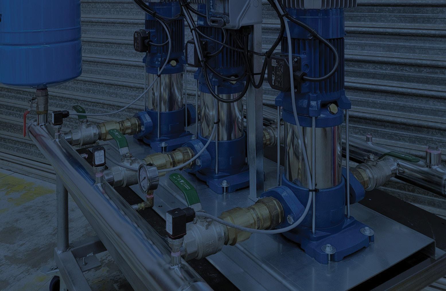



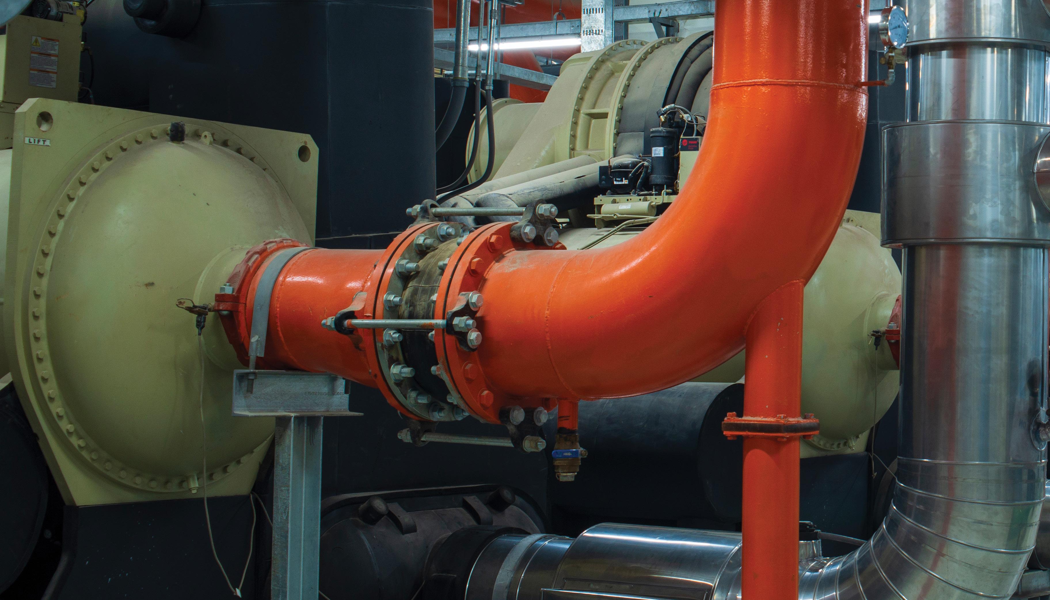
Heating, ventilation and air conditioning (HVAC) generally consumes the largest proportion of energy in commercial buildings, typically accounting for around 40 per cent of total building consumption and around 70 per cent of base building electricity consumption. Unlike other energy efficiency strategies such as plant upgrades that can be more expensive, improving the performance of HVAC systems can provide a quick reduction in energy use and costs. Here, we look at some of the ways pumping systems for HVAC services can be optimised.
There are a number of key end uses in HVAC systems where energy consumption occurs which can be further broken down with the national average being:
• 34 per cent of HVAC energy consumption is from fans for air circulation and ventilation
• 27 per cent of energy consumption is from cooling – most frequently the energy use of chillers for cooling via chilled water, but also the use of direct expansion cooling systems such as packaged air conditioners
• 17 per cent of energy consumption is from heating – most frequently the energy use of boilers for hot water for heating, as well as the use of electric heaters for zonal reheat
• 16 per cent of energy consumption is from pumps for the circulation of hot water, chilled water and condenser water
• Six per cent of energy consumption is from cooling towers for heat rejection, being primarily the cooling tower fan energy HVAC optimisation strategies can vary, but something as simple as changing control algorithms, altering control schedules and set points, and completing minor mechanical repairs and alterations to existing equipment and systems1
The before and after energy consumption of an individual end use for some buildings following an efficiency upgrade can vary by a factor of five or more, especially for fans as they are highly non-linear, and gas as it is often very inefficiently used. However, to realise the benefit, building owners and facility managers need to see energy efficiency strategies as an investment rather than a cost, and implement several strategies at the same time as true optimisation will not be achieved by deploying strategies alone.
The first approach to optimising existing distribution systems is to assess it for problems before establishing system pressure and flow rate requirements and quantifying the installed fan or pump capabilities. This process requires system performance data to be collected over time as logging data such as flow rate, discharge pressure and energy consumption is essential for diagnosing optimum system performance.
Many existing fan and pumping systems in HVAC can improve their efficiency and performance by identifying system problems due to incorrect fan or pump selection and operation. Incorrect fan or pump size can be determined by comparing the system pressure/flow requirements with the fan or pump performance curve. In many cases, the fan or pump performance can be better matched to the system requirements, with maximum efficiency and minimum power consumption achieved by ensuring that the flow and pressure at the fan or pump’s best efficiency point (BEP) closely matches the system operating point.
Where fan or pump distribution systems are not performing optimally, there are a number of solutions that can be explored2:
• Replace old fans/pumps with modern energy-efficient replacements
• Replace constant volume systems with variable volume systems
• High pressure drop – clean filters/strainers and heat exchangers
• High pressure drop – reduce system resistance by upsizing ducts/pipes and fittings, removing unnecessary fittings, removing throttling dampers/valves and installing low pressure-drop plan
• Oversized fan/pump – trim/change impeller, smaller impeller, VSD, two-speed drive, lower rpm. Undersized fan/pump – replace fan/pump or reduce system resistance (optimise flows)
• Multiple fans/pumps operating continuously – review and update the control system
• High maintenance costs – match fan/pump capacity with system requirements; check materials compatibility (corrosive environment etc.)
• High flow rates – adjust system operating temperatures to maximise temperature differentials and reduce flow rates
• Over throttled system – modify fan/pump performance to reduce the need for throttling
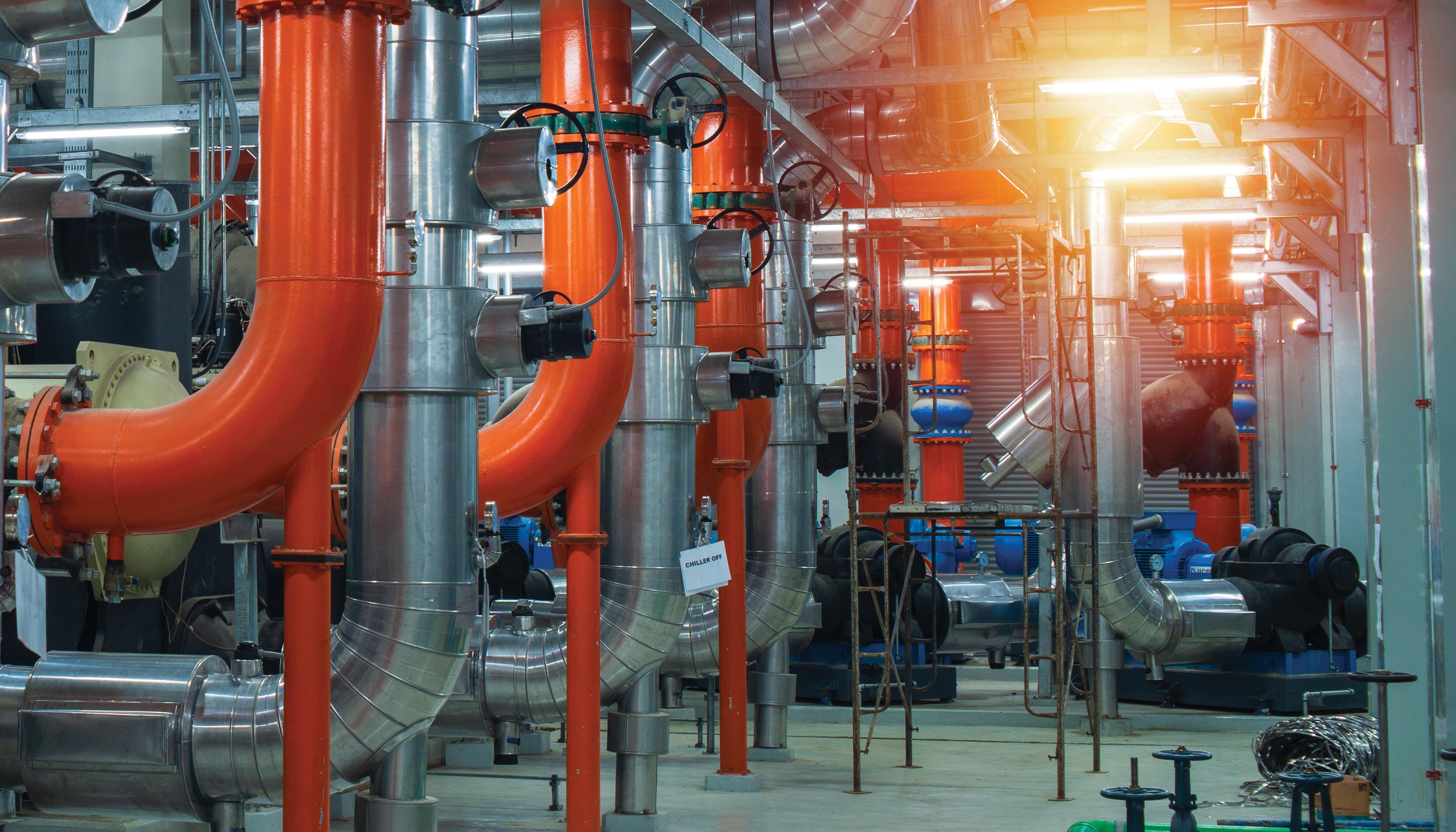
• High power use – rebalance the system to minimise flows and remove throttling
• High distribution losses – review the quantity and quality of the insulation system installed on duct and pipework. Repair defects and upgrade insulation levels to meet contemporary energy standards
• Provide instrumentation to measure pressure, flow and power use
• Repair seals and packing to minimise losses
Optimisation through variable speed controls
A common way of optimising an HVAC pumping system is through the installation of variable speed drives to the fan, pump or compressor motors. There are a number of opportunities for this to be implemented.
Secondary chilled water pumping (differential water rest)
Secondary chilled water (SCHW) pumping systems distribute chilled water (CHW) from the CHW plant room to the various distribution systems such as air handling units (AHUs) and fan coil units (FCUs). Pumping of CHW through chillers is not carried out by the SCHW, rather this is done by the primary CHW pumps.
An optimisation strategy for SCHW pumping systems that have two-port modulating valves and hence a variable flow, is using system differential pressure reset control. Variable secondary chilled water pumping that uses this strategy can minimise the pumping energy required to distribute the chilled water, and can reduce energy consumption by up to 30 per cent.
For a three-port modulating valve (constant flow) system, it will need to be converted to a two-port by modifying the existing valve through shutting down the bypass port or replacing it with two-port valves.
The control logic of this optimisation strategy is also applicable to new SCHW systems.
Typically the control of CHW secondary pumps in variable flow distribution circuits is achieved by setting the pump to maintain a constant pressure set point, which is usually selected for the peak design CHW flow. The problem with this is that the pump maintains too high a static pressure most of the time, therefore wasting energy.
For such systems, energy consumption can be reduced during part-load conditions by reducing the speed of the SCHW pump incrementally (CHW pressure set point reset) to maintain an opening of 95 per cent of the most open CHW valve; thereby delivering CHW at the lowest possible pressure while still satisfying the CHW needs of all CHW distribution systems.
Optimised SCHW pumping is typically a cost-effective way to improve energy efficiency of HVAC systems as it requires minimal investment and immediately reduces the energy
consumption of the system by reducing its load. However, costs will significantly increase if two-port valves need to be retrofitted.
The energy efficiency of HVAC systems in part-load conditions can be further improved by controlling the head pressure of water-cooled condensers. This is achieved by installing VSD controllers to pumps to control the head pressure of single water-cooled direct expansion (DX) units, as well as using condenser water (CW) modulating head pressure valves to control head pressure of multiple water-cooled, AC DX units supplied by CW from one CW pump. This strategy has the potential to reduce the energy consumption of CW pumps by ten to 30 per cent, and improve control and reliability of AC systems during part-load conditions.
Typically, water-cooled condensers maintain head pressure by ensuring constant CW flow as per manufacturer’s requirement, or constant CW flow as per HVAC system designer’s requirements. Both ensure sufficient heat rejection during the hottest O/A conditions; however, they potentially compromise part-load performance of associated AC DX units due to the risk from over-condensing. Furthermore, the additional CW flow results in wasted energy by the CW pump, as often CW continues to circulate through AC units even when they are not in operation.
During lower ambient air temperatures, the AC load typically decreases while the capacity of condensers increases. Therefore energy savings are possible by reducing the condensing pressure of the refrigeration cycle. The reduced pressure can then be maintained by VSD-controlled pumps, resulting in additional energy savings compared to a fixed speed pump.
Variable head pressure control is typically a cost-effective way to improve energy efficiency in HVAC systems. While it does require some investment in new drives, valves and controls, an immediate reduction in energy consumption can be realised by reducing system pump power.
This article covers a few ways that HVAC pumping systems can be optimised, however there are many more strategies that can be implemented across the entire system. In order for HVAC optimisation strategies to save significant energy and money, a three-pronged approach addressing infrastructure design, system automation and optimisation, and ongoing monitoring and maintenance is needed. A system that can automatically respond to the environment will deliver the greatest energy efficiency.
1. https://www.environment.nsw.gov.au/resources/business/150317HVACGuide.pdf 2. https://www.environment.nsw.gov.au/resources/business/150317HVACGuide.pdf
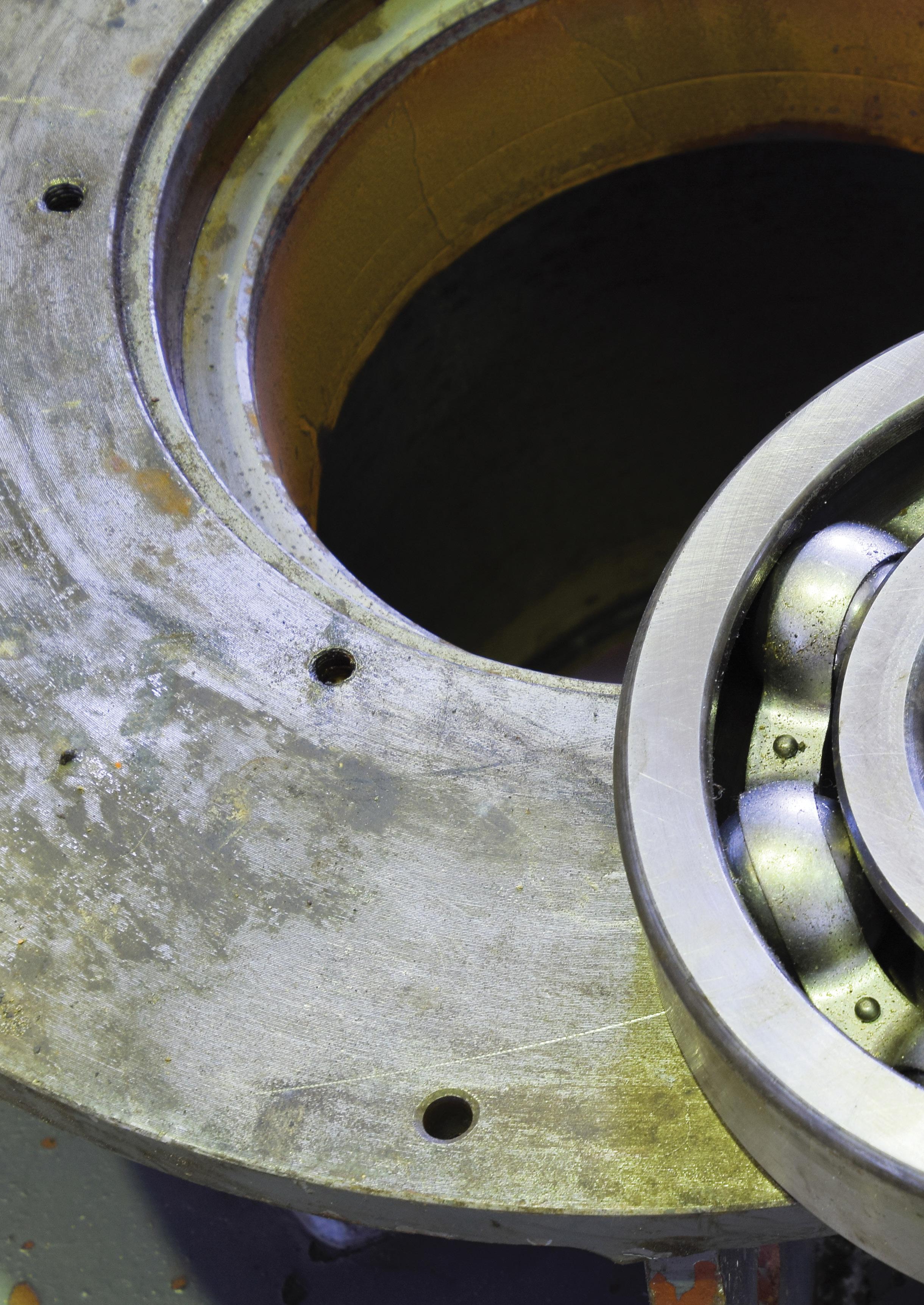
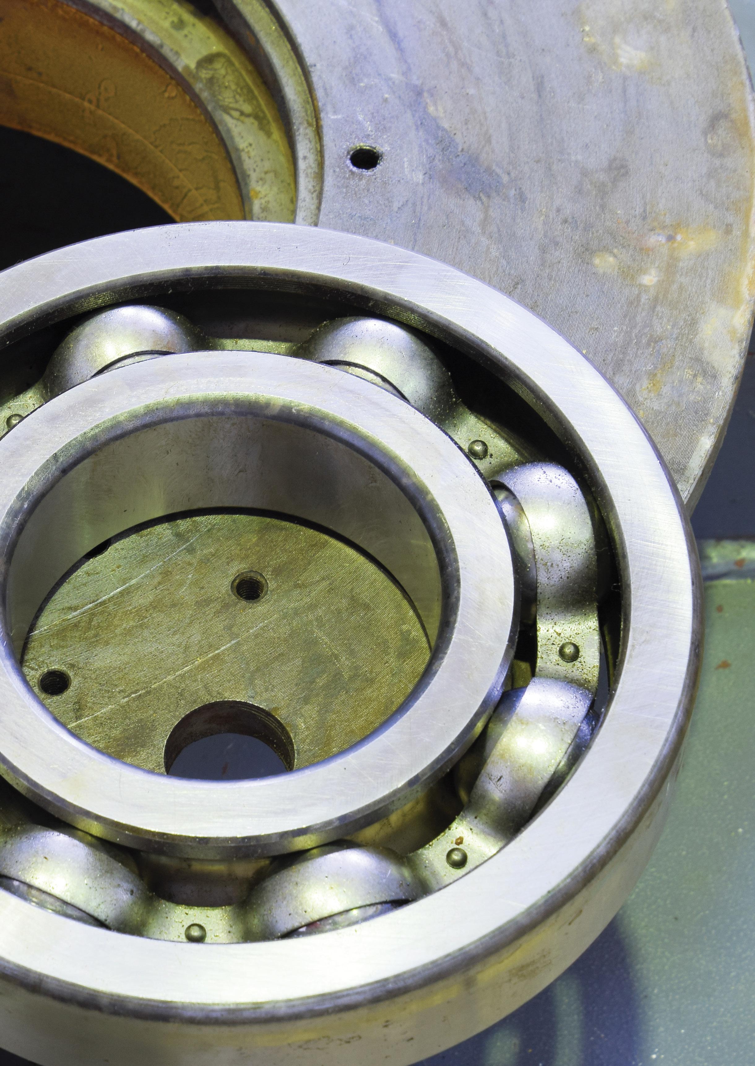
In the over six decades since 1960, hundreds of papers, articles, and conference proceedings have been published under the broad classification “process pump improvements”. However, most of these have addressed improvements in pump hydraulics for reasons of initial cost reduction and enhanced pump efficiency. Pump marketers have always been aware of this because pump buyers use these two parameters to decide which pumps to buy. Regrettably, these selection priorities lead to “benign neglect” of the power ends of process pumps, although a few books have documented how and why the power ends (bearing frames) deserve considerable attention¹²³. This article gives a few pointers on how to obtain improved power ends.
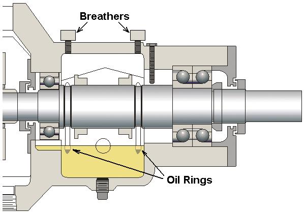
The generic bearing housing cross-sectional view of Figure 1 makes a compelling case for pump upgrading. It contains at least five vulnerabilities and risks that are unacceptable to best-of-class users:
a. Oil rings (“slinger rings”) are used to lift oil from the sump into the bearings. Yet, under certain adverse conditions, these oil rings will malfunction¹. We should make an effort to understand how and why oil rings tend to malfunction².
b. The back-to-back oriented thrust bearings are not located in a cartridge. However, cartridge mounting will facilitate upgrading from high-risk, loose-running oil rings (slinger rings) to low-risk flinger discs. Flinger discs are secured to the shaft and will pick up oil even if the pump shaft system is at slight angles.
c. Bearing housing protector seals are missing from this picture. Not using bearing protectors or installing an inferior type of bearing protector will decrease bearing life. The incremental cost of a well-designed product often pays for itself in a mere few weeks of ownership.
d. While the bottom of the housing bore at the radial bearing shows the desired oil return passage, the same type of oil return or pressure equalisation passage will be needed at the six o’clock position of the thrust bearing. Without a drain hole, trapped oil will overheat and become viscous tar or black coke.
e. There is uncertainty as to the type or style of constant level lubricator that will be provided; unless specified, the best one (with pressure equalisation) is rarely found on new pumps.
In addition to the more widely publicised hydraulic selection criteria, each of the above mechanical or power-end issues merits further explanation and will be discussed next. The considerations are confined to lubrication issues on process pumps with liquid oil-lubricated rolling element bearings. A majority of process pumps in use today fall into the oillubricated rolling element category (small pumps with greaselubricated bearings and large pumps with sleeve bearings and circulating pressure-lube systems are not included in this discussion).
It has been estimated that 25 per cent of all failures are preventable, but not prevented because of an arbitrary decision that is simply not rooted in knowledge and experience. For example, a decision to use the cheap oil may overlook the fact that cheap oils often lack demulsifiers, or anti-foaming agents, etc.
Warding off ‘black oil’ requires close observation of possible contributors. Black oil can be attributed to approximately 15 per cent of all failures that are predictable, but not predicted. For example, the random appearance of ‘black oil’ is attributable to O-ring degradation of a certain style of bearing protector seal. The bearings will soon fail but nobody has read the books and articles that describe the occurrence (the occurrence should be linked to a certain risky design feature on a widely used product). Or, as was shown in Figure 3, oil is trapped behind a bearing.
‘FRETT’ - Force, Reactive Environment, Time, Temperature
Bearings, lubricants, and lubricant application methods all merit close attention. It is important to realise that, whenever gaskets, bearings, seals, shafts, housings, or any of the many thousands of other equipment components fail, the underlying causes are always found in one or two of four mechanisms described by the acronym ‘FRETT’, meaning force, reactive environment, time and temperature. Knoxville (TN, USA)-based company System Improvements has made FRETT the core of a potent and popular troubleshooting and failure analysis training course called ’Equifactor®’. Whenever there is a deviation from normal, say black oil is found in a bearing housing, at least one of these four failure mechanisms will have contributed to the seemingly random and often very sudden appearance of darkened lubricant. Equifactor® rather quickly zeroes in on the root cause of this, and many other often elusive deviations.

Figure 2: Bearing housing protector seal with optimally placed axial or diagonally moving O-ring (Source: AESSEAL Inc., Rotherham, UK and Rockford, TN)
While black oil has been studied in the past, the underlying causes seem to have remained hidden from many researchers³. An oil analysis will uncover contaminants that are either carbon (overheated oil) or particles of elastomeric O-rings that have frayed or decomposed for some reason. In any event, one will have to find and eliminate the source of the black residue. Black oil inevitably originates either from overheating the oil or is due to O-ring damage². Both deserve much more attention.
Among the more elusive reasons for overheated oil, we find oil ring slippage and also degradation of a so-called ‘dynamic O-ring’ that is placed between the rotating and stationary components of a bearing protector seal. Common sense and experience are of great value here; accordingly, a preview of bearing housing protector seals is enlightening.
Bearing protector seals with O-rings contacting a generously contoured area (lower part of Figure 2) are obviously less likely to undergo O-ring degradation than products designed with a sharp groove opposite the O-ring. In addition, axially or diagonally moving O-rings are clearly superior to O-rings designed to move radially. Some designs also risk encountering the sharp corners of an O-ring groove.
Part 2 of this article will appear in the next edition of Pump Industry.
Heinz P. Bloch resides in Montgomery, Texas. His professional career commenced in 1962 and included long-term assignments as Exxon Chemical’s Regional Machinery Specialist for the United States. He has authored or co-written over 800 publications, among them 24 comprehensive books on practical machinery management, failure analysis, failure avoidance, compressors, steam turbines, pumps, oil mist lubrication and optimised lubrication for industry. Mr. Bloch holds B.S. and M.S. degrees (cum laude) in Mechanical Engineering. He is an ASME Life Fellow and was awarded life-time registration as a Professional Engineer in New Jersey. He is one of ten inaugural inductees into NCE’s Hall of Fame, which honors its most distinguished alumni.
References
and
Optimized Equipment, Oil Mist Technology and Full Standstill Protection, DeGruyter Publishing, Berlin/Germany, ISBN 978-3-11-074934-2
Pump Wisdom: Problem Solving for Operators and Specialists, 2nd Edition, Wiley and Sons, Hoboken, NJ, ISBN 978-1-11-974824-3
Life Extension of Pumps, Gas Compressors, and Drivers, DeGruyter Publishing, Berlin/Germany, ISBN 978-3-11-067413-2

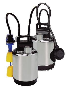

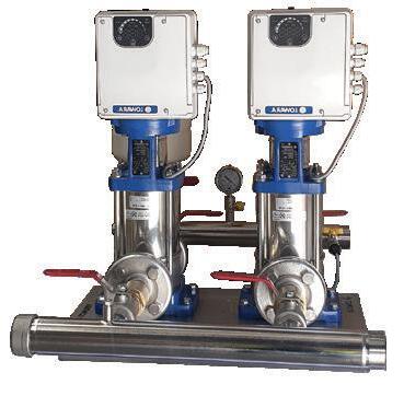
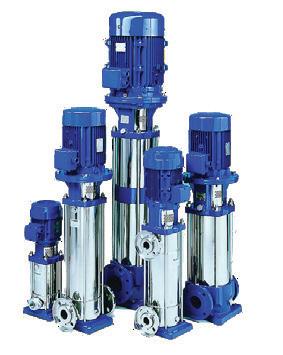

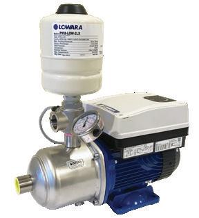
*This is a second discussion on pump test acceptance grades based on the Hydraulics Institute white paper for Understanding the Effects of Selecting a Pump Performance Test Acceptance Grade
The introduction of AS ISO9906: 2018 has opened the Australian pump industry to a wider range of pump test acceptance tolerances that may be requested by a purchaser. This article continues on from the discussion in part one, and will look briefly at the relation between the various acceptance tolerances, pump system application, pump delivery lead times and energy consumption.
Table 1 - ANSI/HI
a Efficiency is a calculated value that is dependent on pump power input and, therefore, either minimum efficiency or maximum pump power input at the guarantee point can be specified, but not both.
Table 1, extracted from ANSI/ HI14.6 (similar to ISO9906), provides the acceptance grades with their particular tolerances, but how is the best way a specifier can nominate a particular acceptance grade?
The selection of an acceptance grade determines the performance tolerance of a pump test agreed upon by the user and the manufacturer. While these tolerance bands include the accuracy of the measuring equipment, it is only a very small portion of the total allowable
tolerance. The majority of any variations in performance may be due to a number of issues related solely to the pump, and perhaps the pump driver.
As a guide to the purchaser, AS ISO9906 and HI ANSI14.6 both include a table of ‘Default test acceptance grades’ for a factory test where a guarantee point has been given but no acceptance grade is specified. The table is based on the selection of eleven industry applications, where applications are nominated simply as ‘Electric power
industry’ or ‘General industry’ or similar. Should a purchaser not specify an acceptance grade and the ‘Default test acceptance grade’ table is utilised, the standard only requires the head and flow to be guaranteed. There is no requirement for the manufacturer to provide a guaranteed power and/or efficiency. A purchaser needs to provide a clear and acceptable specification for a factory pump test to achieve a satisfactory outcome for both parties.
Diagram 1 illustrates in a general form some typical applications and how an acceptance grade may be decided upon and selected.
Today, with a worldwide focus on energy consumption, it is presumed power and efficiency will always be a consideration in the decision to nominate an acceptance grade. But higher degrees of accuracy in testing and performance may come with an impact on cost and delivery. Depending on the pump size, design and the manufacturing operations, an increase in performance will come with varying cost implications. Simply, the higher the precision used in manufacturing and testing, the smaller the expected variations in test results. Perhaps with a smaller pump, the variation in cost by the manufacturer to guarantee a better efficiency may outstrip the cost of the additional power necessary over a given period. The Hydraulics Institute white paper provides in Table 2 an illustration of possible impacts on costs and delivery on tighter acceptance grades. This is very general, pump manufacturers will all differ in their approach and outcome on testing costs and delivery.
Previously, we noted that one of the most important reasons to have a manufacturer test a pump is to have baseline data for diagnostic purposes in the future and that almost any acceptance grade might suffice. All pumps are installed into a system of some description, and the system resistance curve (flow against head) of the piping system is predominantly a calculated curve or value.
It is only via the installation of a factory-tested pump into the system that enables system resistance to be verified at commissioning. However, it is rare to look upon the pump and system in this way. Typically, an initial pumping/piping system problem is often diagnosed as a pump underperforming; perhaps it has a lower than expected head and is using more power, or generating too much head as the case may be. It is a factory-tested pump with its guaranteed performance curve that will potentially rule out a genuine pump underperformance on site. Any future degradation in either pump or the piping system will more easily be identified over the operating lifetime.
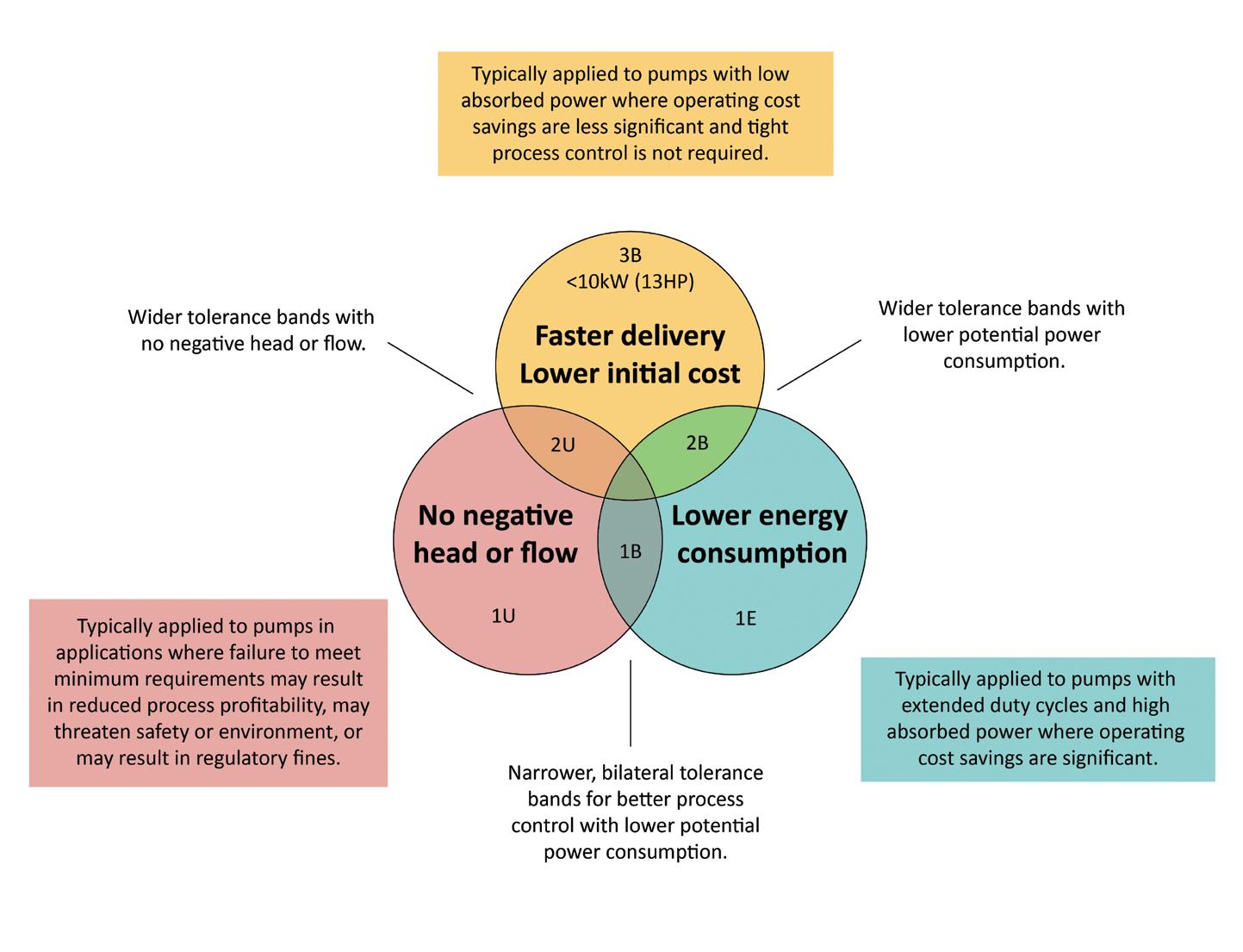
Without efficiency or power specified
With efficiency or power guaranteed*
* Efficiency is a calculated value that is dependent on pump power input and, therefore, either minimum efficiency or maximum pump power input at the guarantee point can be specified, but not both.
0 = no additional cost or delivery lead time impact. The greater the number of $, the greater will be the cost incurred. The greater the number of +, the longer delivery lead time impact.
The Hydraulics Institute white paper for Understanding the Effects of Selecting a Pump Performance Test Acceptance Grade and a webinar are available online at no cost. Its 17 pages are much more explanatory on many other issues, including crossing steep or shallow system curves, the interactions or trade-offs between each acceptance grade, the intended operating system, possible cost and delivery implications.
It is recommended that engineers specifying and requiring manufacturer tested pumps take the time to read and understand the benefits and possible implications of nominating a particular acceptance grade.
The white paper can be found on the Pump Industry Australia website https://pumps.org.au/product-category/publications/.
The PIA’s Australian Pump Technical Handbook is a cornerstone text for the Australian pump industry and, in our opinion, a must-have for anyone who deals with pumps on a regular basis. In this ongoing series, we feature abridged chapters from the classic book to showcase the various areas covered and to reacquaint readers with the technical aspects of pumps. In this issue, we continue exploring energy efficiency in pumping systems, focusing on lifecycle costs.
Lifecycle cost (LCC) is an important factor to keep in mind when building or upgrading an existing pumping system.
LCC can be estimated for the lifespan of a pumping installation from initial design to final decommissioning using the industry standard formula defined by the The Hydraulic Institute.
LCC = Cic + Cin + C e + C o + C m + C s + C env + Cd
Cic = Initial costs
Cin = Installation and commissioning costs
C e = Energy costs
C o = Operational costs
C m = Maintenance and repair costs
C s = Downtime costs
C env = Environmental costs
Cd = Decommissioning costs
Of the costs represented in the formula, Cic, Cin, Ce, Co and Cm are the main variables with respect for pump selection. Due to this, comparisons of LCC are limited to these factors, and Cs, Cenv and Cd are grouped under the general heading of “other costs”, as they largely occur later in the equipment lifetime and are difficult to accurately estimate.

Graph 1: Typical pump lifecycle cost profile.
Graph 1 shows a typical breakdown of lifecycle costs. However, where there is a poorly selected and inefficient pump, energy costs – as well as operating and maintenance costs – should increase. On the other hand, while a correctly selected pump and appropriately sized pipework system might increase the capital cost, there is the long-term advantage that any differential cost should be compensated for by lower energy, operating and maintenance costs over the lifetime of the installation. Because of this, it is important to approach the purchase or upgrade of a pumping system as an investment decision, and apply the same business analysis to determine the payback period for a more efficient solution.
When designing a new pumping system, the LCC analysis is usually estimated based on current energy prices, and labour and parts costs. However, if it is considered relevant to the business, it is also possible to overlay the time value of money to the analysis. In this case, analysis should also include some allowance for likely increases in power rates and labour costs.
The LCC estimate should be applied to all pumps and components offered for a new system, and should help to establish the optimum solution. A simplified analysis of system costs versus pipe diameter to illustrate this methodology can be found in the Australian Pump Technical Handbook. However, it should be noted that for pump installations that operate more than 2,500 hours per annum and for more than ten years, the power costs usually outweigh all other costs.
LCC analysis to reduce losses in pumping systems
Research has been carried out in the US and Europe to analyse LCC in order to develop strategies for reducing losses in pumping systems and reducing power consumption.
This research includes:
• Pumping systems account for 20 per cent of the world’s electrical energy demand and 25-50 per cent of the energy usage in industrial plants
• Energy usage depends of design of the pump, design of the installation and the way the system is operated
• Reducing energy costs should have environmental benefits With evidence showing there are cost savings associated with determining LCC, there are a number of possible explanations as to why LCC has not been widely embraced. New installations:
• Many only look for short-term returns
• Design focus is more on capital and installation costs, while less consideration is given to energy costs or power and maintenance costs
• Design and construct contracts encourage selection of the lowest bidder for pump supplies
• Some aspects of LCC calculation require assumptions to be made which may influence the payback period
Existing installations:
• There is a mentality of "if it’s not broken, don’t fix it", along with entrenched opinions on equipment performance
• Considerations for cash flow or production output override consideration for power consumption
• There is inadequate data about actual plant performance over time, as well as poor records of maintenance and repair costs
Selecting the best pump for a particular application requires a detailed description of the conditions of service and an accurate calculation of system resistance. A system curve is useful to assess the limits of operation, allowing pump suppliers to recommend appropriate pump selections.
In many cases, operational reliability of a plant is a key factor, and needs to be considered against the sometimes competing need for high efficiency.
While the focus of these past six articles about efficiency operations of pump systems has been on centrifugal pumps, similar considerations would be applied to positive displacement pumps. Positive displacement pumps are normally used for fluids with high viscosity, for low flows and high pressures, and where an accurate flow is required for every pump revolution. The efficiency of these pumps is dependent on a determination of friction and leakage losses. Friction losses in the system depend on the rate of flow, whether it is constant or pulsating, and fluid characteristics.
It is important to ensure the validity of the data provided by suppliers as tolerances are often applied to performance data that are not accounted for in the design process. Therefore, efficiency of the total plant should be evaluated on verifiable performance data rather than published data in catalogues as this data may not be sufficiently accurate for design purposes.
When designing a pumping system, care should be taken for all components selected, including piping, valves and drive options, and experience in this discipline can often help to avoid the common pitfalls and traps that occur in some installations. With a wide variety of drive options available, the final selection is often dependent on operational considerations.
While looking at selecting pumps with high efficiency can be useful, taking a system approach is more likely to result in long-term benefits. Calculating LCC of the entire system is appropriate for evaluating the best return on investment of a pumping system over its lifetime.
Further information and detailed diagrams, equations and schematics can be found in the Australian Pump Technical Handbook, available from the PIA website. In the next edition of Pump Industry, we continue to explore pump materials.

The pump industry relies on expertise from a large and varied range of specialists, from experts in particular pump types to those with an intimate understanding of pump reliability; and from researchers who delve into the particulars of pump curves to experts in pump efficiency. To draw upon the wealth of expert knowledge the Australian pump industry has to offer, Pump Industry has established a panel of experts to answer all your pumping questions.
As energy costs are rising globally, increasing operations efficiency of wastewater treatment plants gains importance. This edition of Ask an Expert will look at the first automated progressive cavity pump in the world. The award-winning new technology enhances process efficiency, extends rotor and stator life and considerably reduces TCO.
Q. What makes this new pump solution special?
A: It is the world’s first automated and digital progressive cavity pump. Through digital monitoring and an innovative new design, the pump can analyse itself and adjust the operating point of its conveying elements in an automated manner. The design incorporates a retensioning device, which automatically adjusts the rotor-stator clamping, quite simply from a distance with a click of a button. In this easy and more importantly, highly precise, repeatable way, the pump flow rate is always kept at the optimum operating point. A novelty in our industry.
Q. Why is it important and economically worthwhile to adjust the rotor-stator clamping?
A: The rotor-stator clamping directly influences the pump’s performance as it defines the sealing of the oscillating
cavities formed by rotor and stator. It directly affects important parameters such as flow, energy consumption, wear or lifetime. However, the ideal clamping is highly dependent on nonstatic parameters such as temperature, pressure or properties of the conveying medium (e.g. dry solid content) and unavoidable wear. Hence, the knowledge of the exact operating conditions by digital monitoring and the possibility to account for them by an automated adjustment of rotor-stator clamping offers a huge potential in terms of increased lifetime, less consumption of energy and resources, increased process safety and minimised operating cost.
Q. How does this technology work?
A: Technically, the pump design includes a hydraulic control unit and adjustment segments, which apply pressure on the stator resulting in a given rotor-stator clamping and sealing,
respectively. Through the mechanical design and control, the pump can adjust the rotor-stator clamping to the optimal operating point in an automated manner. The control and hydraulic unit regulates the clamping and allows connection to SCADA or the pump monitor. Additionally, digital monitoring and cloud services enable remote adjustment to optimise pump efficiency, and with advanced analytics, the implementation of predictive and forward-planned maintenance.
Q. What does the operator have to do?
A: A remote click from the control room or a touch on the on-site pump monitor or tablet is all it takes to adjust the stator clamping so that the pump performance is always top-notch. Special tools are no longer required. The service technician responsible can easily make all changes via the control room.
Q. What are the greatest advantages of this automated pump solution?
A: In a nutshell, it makes day-today business easier, safer and more efficient. Advantages include reduced maintenance, less wear, lower spare parts costs and a significantly longer pump service life due to the simple automated operation and a more frequent and early stage adjustment of the stator clamping. Remote locations are just a click away. Time-consuming walks for manual adjustments on the plant, drives to remote pumps or the hassle with mechanically readjusting pumps that are difficult to access are outdated. The SCT AutoAdjust technology is capable of monitoring process-critical factors and drastically reducing maintenance times to guarantee plant availability and productivity.

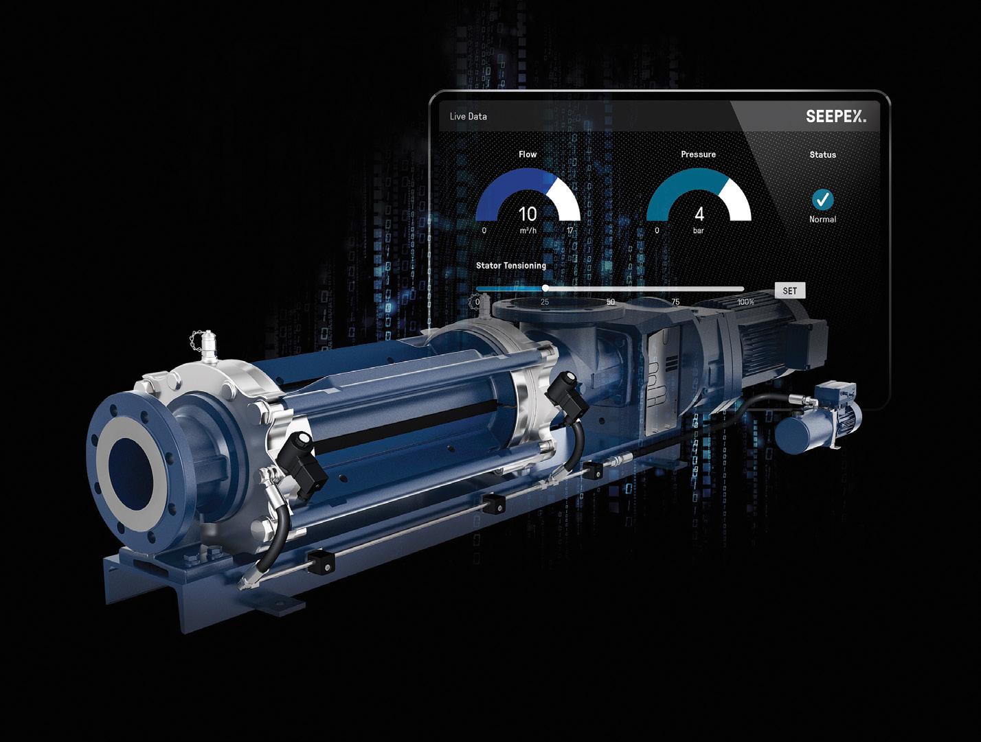
The world’s first automated progressive cavity pump can hydraulically re-tension the stator clamping.
Peter Vila, Managing Director of SEEPEX Australia, is a progressive cavity pump expert. He has been involved with pumps for over 40 years. Peter spent the first five years repairing pumps and the following 35 years in technical sales, 20 of which have been with SEEPEX progressive cavity pumps.
For more information on progressive cavity pumps, please contact SEEPEX Australia on (02) 4355 4500 or at info.au@seepex.com
A MATTER OF ADJUSTMENT SCT A uto A djust
With SCT AutoAdjust easily set the stator clamping of a progressive cavity pump to the optimal operating point. Life cycle costs are reduced at the push of a button.
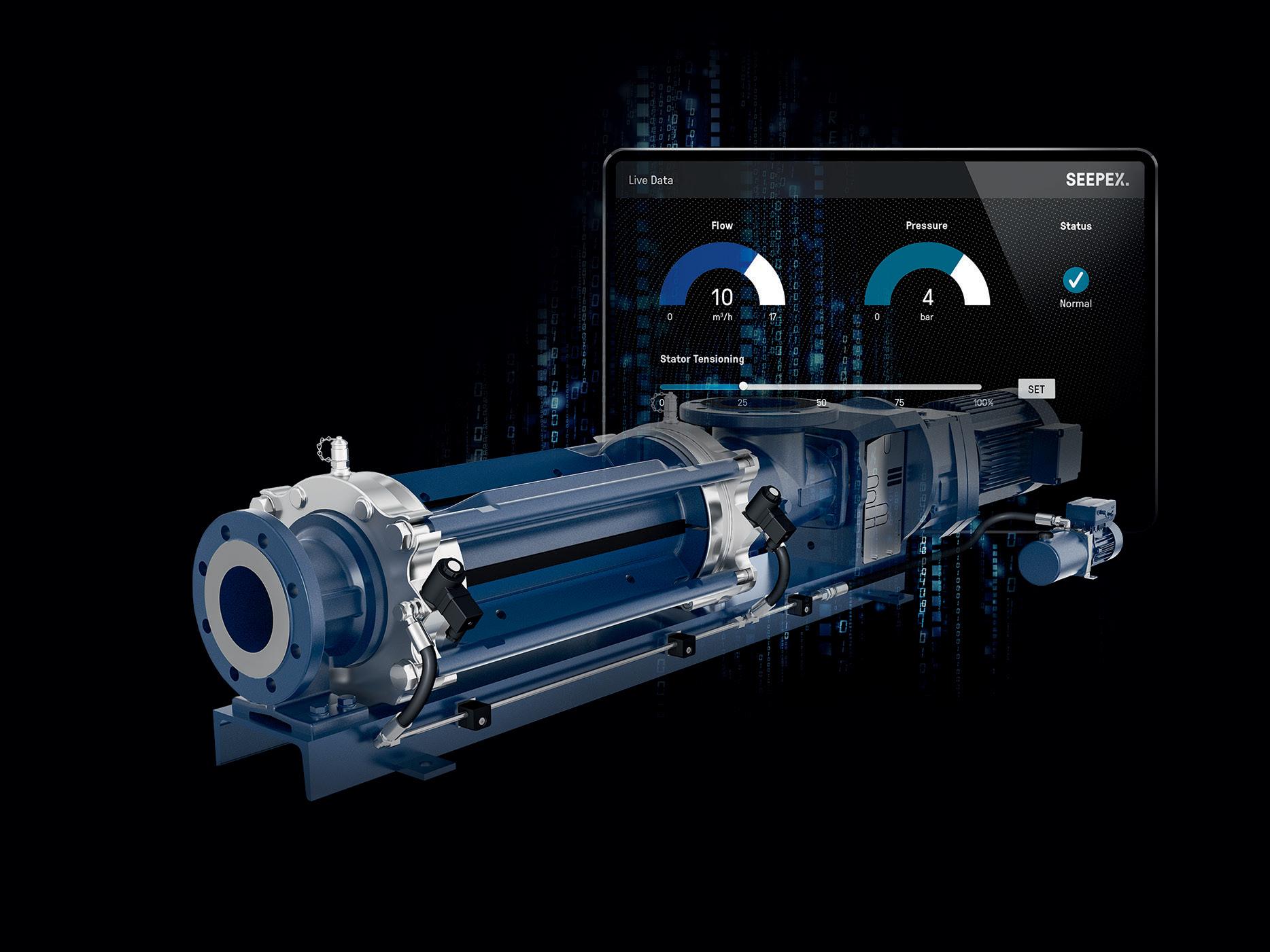
y Best conveying capacity and productivity: always operating at the optimal level
y Immediate adaptation to changing process conditions increases overall efficiency
y Reduced downtime through predictive maintenance via cloud connection
y Extended lifespan due to adjustment of the stator clamping
SEEPEX Australia Pty. Ltd. T +61 2 43554500 info.au@seepex.com www.seepex.com

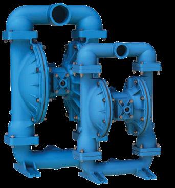
Adiaphragm pump, part of the positive displacement pump family, is a versatile and reliable pump that can be used across most industries where fluid transfer is required. It uses a combination of the reciprocating action of a set of diaphragms and valves on either side of the body to pump fluid. A diaphragm pump can either be mechanically driven with an electric motor or engine, or airoperated with compressed air. They can come in a range of materials including aluminum, cast iron, Hastelloy-C, Alloy 20, stainless steel, PVDF, polypropylene, and conductive polypropylene acetal, therefore ensuring that they can be made to suit a range of applications.
One key feature in the operation of a diaphragm pump is pulsation, that being, the alternation of suction and discharge resulting in liquid flowing intermittently through the pump. An injection syringe is a very basic form of diaphragm pump and is useful in illustrating this concept of pulsation in action. Pulling the piston of the syringe back creates suction that pulls the liquid into the cylinder while pushing the piston forward discharges the liquid through the needle of the syringe (Figure 1).

In the same way, a diaphragm in a pump moves inward and outward toward the body, working in combination with the check valves to draw in and discharge the fluid out of the pump. Figure 2 below shows that without the check valve in place, air would simply flow into the cylinder when the piston
is moved outward thereby preventing any suction.
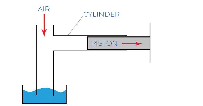
Figure 3 shows the check valve in place which serves to prevent fluid flowing into the cylinder. This creates a negative pressure within the cylinder and allows fluid to be drawn up from the bottom once the piston is moved outward.
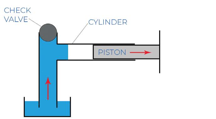
Figure 4 shows the cylinder dispelling the liquid when the piston is pushed inward.
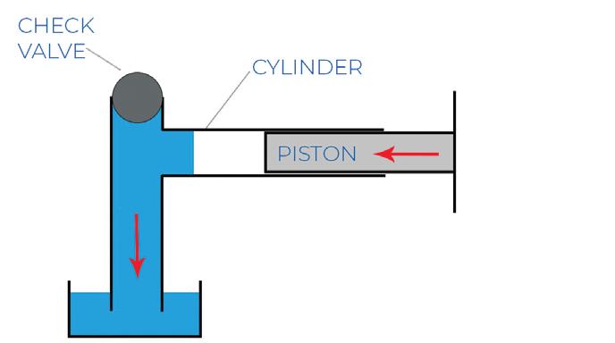
Figures 5 and 6 further help to illustrate the operation of a diaphragm pump that uses two check valves, one on the suction side and the other at the discharge side. These valves alternate between open and closed, working
with the diaphragm to achieve suction and discharge.
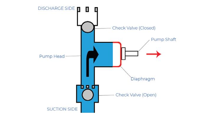

One of the many elements to consider when selecting a pump is the type and viscosity of the liquid being pumped. In general, a diaphragm pump is well-suited for use with a wide range of fluids, including high and low viscosity liquid, high and low dense liquids as well as clean and abrasive liquids. This includes liquids such as volatile solvents, corrosive chemicals, viscous, shearsensitive foodstuffs, pharma products, sticky fluids, pharma products, dirty water, smaller solids, abrasive slurry, creams, oils, and gels.
While it is true that diaphragm pumps provide a versatile and reliable option when pumping highly viscous or dense fluids, ensuring you have the right pump for the right application involves a more thorough set of considerations. If in doubt, consult your pump supplier.
The Trusted Choice For Customers Worldwide:
Consistent high per formance
Suitable for the harshest environments and over the most challenging terrains
Ex tensive R&D
Ongoing technical suppor t


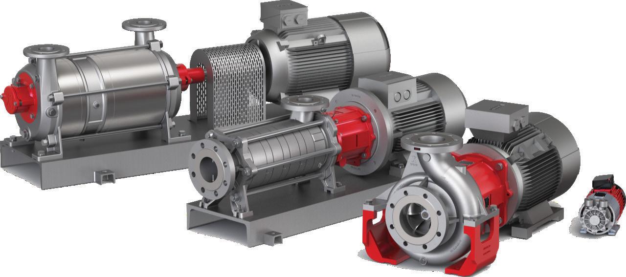
Our specialised products are principally used in medical technology, the chemical and pharmaceutical industries, cooling and tempering appliances and in the plastics industry. Speck is very export-oriented and employs over 575 staff members worldwide.
Products from Speck are characterised by a wide range of available variants which is specially tailored to the customer’s needs. Our staff in the Technical Department are constantly working on new solutions and further developments to our existing products that help our customers move forward – day in, day out.
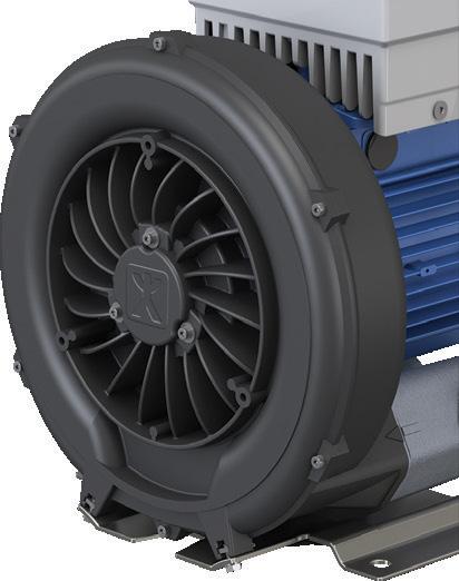
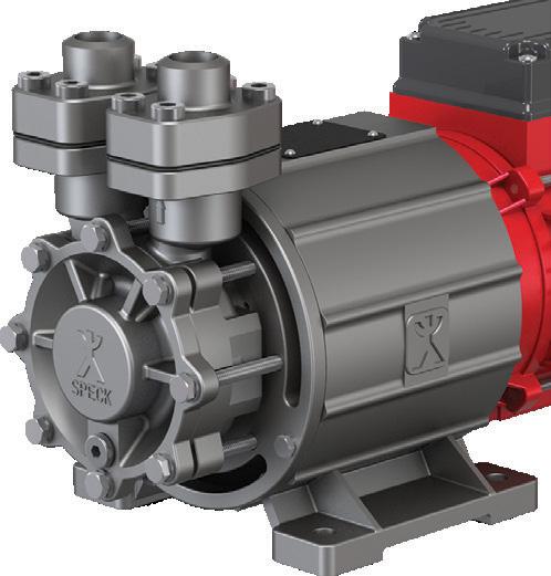
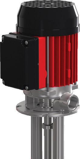
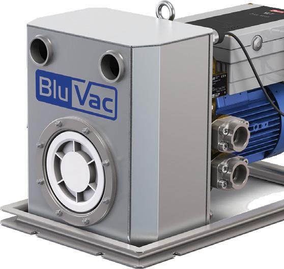
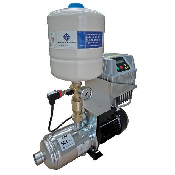
FPS ISO Series
Designed for both industrial and agricultural application
Multistage versatile pump set, combining and FPS MH pump with DrivE-Tech
Pioneer Series
Large Range of Heavy Duty Dewatering Pumps, Auto Self Priming, Wet Self Priming and End Suction Centrifugal, Solids Handling & abrasion resistant pumps.
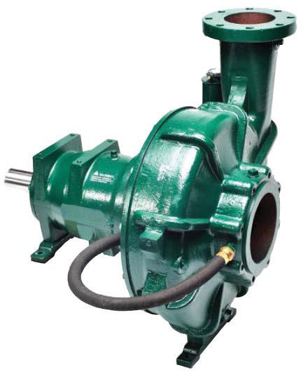
HWR Series
Wear-resistant pumps manufactured with highchrome white iron to maximize resistance against destructive abrasives and maintain peak performance in light slurry applications.
SolarPAK
All in one, optimal preforming high-output package, containing a submersible pump and motor.
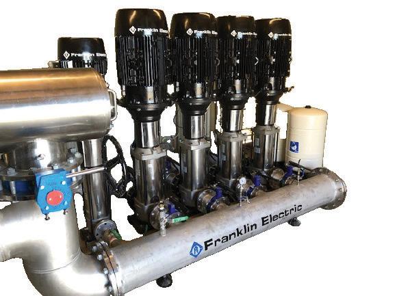
Vertical multistage pump booster and pressure system, designed in various combinations to suit, whether it be Industrial, Building Services, Commercial, HVAC, Domestic or irrigation applications. Ranging from a singular pump system through to a complex 8 piece design.
Dandenong South Facility: 106-110 Micro Circuit, Dandenong South, Victoria, 3175 Telephone: (61 3) 9799 5000


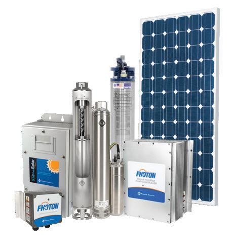

Sunshine West Facility: 1-67 Proximity Drive Sunshine West, Victoria, 3020 Telephone: (61 3) 9988 1650