Repetitive pump failure: the unnecessary evil
Reassessing lifetime lubricated sealed bearings

















• Specifically
• Multiple configurations
• Compact yet powerful





• A giant step up in efficiency — up to 15% higher than other brands
• E xtended product life




Pump Industry Australia Incorporated
Kevin Wilson – Secretary PO Box 55, Stuarts Point NSW 2441 Australia
Ph/Fax: (02) 6569 0160 pumpsaustralia@bigpond.com
Ron Astall – President United Pumps Australia & Astech Consulting Services
John Inkster – Vice President Brown Brothers Engineers
Mike Bauer – Councillor Dynapumps
Frankie Camilleri – Councillor John Crane
Martin O’Connor – Councillor KSB Australia
Alan Rowan – Councillor Life Member
Keith Sanders – Councillor Australian Industrial Marketing & Life Member
Ashley White – Councillor Davey Water Products
In the last issue of this magazine we learnt that as a result of European Union Energy Efficiency Directives, all large EU enterprises will be required to undertake energy audits by December 2015. In the UK alone this is expected to lead to energy saving benefits of £1.6 billion.
The BPMA’s Steve Schofield outlined their related pump system auditor training and accreditation programs. In the US, in 2013 the power industry had over a $US6 billion spend on energy efficiency programs. This year it is expected to top $US9 billion. That’s a lot of money!
When attending the Hydraulic Institute annual meeting in Florida in February I learnt that the Hydraulic Institute is now also developing pump system auditor training and an accreditation regime. While there I met Erin Hope from Bonneville Power and Geoff Wickes from the North West Energy Alliance; both of whom are actively involved with the Hydraulic Institute’s energy efficiency programs. I expressed surprise at how the utility companies were actively encouraging their customers to buy less of their product (electricity). Whilst there are some government incentive programs in Australia, I am not aware of incentives to this scale from the Australian power suppliers.
Erin and Geoff explained that one of their biggest problems in the US power industry is under capacity and limited opportunity to increase generating capacity. These incentive programs have been highly successful and have reduced the number of brown-outs and supply problems. Often where previously, additional poor stations had been mooted, they are now considered to be unnecessary. They had initially been focusing on lighting and now this focus is turning to pumps. An energy efficiency rating and labelling program for pumps is now being developed; similar to what we see in Australia on refrigerators and washing machines. Energy efficiency has been PIA’s primary emphasis for a while and this will not go away. In the process industries it is believed that typically 70 per cent of installed electric motor capacity is for pumps.
This may be seen as a challenge for the pump industry but in reality it is a giant opportunity – and one we should all embrace.
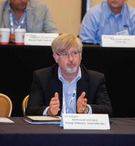
Ron Astall President, Pump Industry Australia
Cover image highlights our story on the innovative new underground network that will cool Brisbane’s CBD buildings.
3,159
Published by Monkey Media EnterprisesABN: 36 426 734 954
PO Box 3121
Ivanhoe North VIC 3079
P: (03) 9440 5721
F: (03) 8456 6720
monkeymedia.com.au
info@monkeymedia.com.au
pumpindustry.com.au
magazine@pumpindustry.com.au
Publisher and Editor: Chris Bland
Managing Editor: Laura Harvey
Marketing Consultant: Aaron White
Associate Editor: Michelle Goldsmith
Creative Director: Sandy Noke
Graphic Designer: Alejandro Molano
ISSN: 2201-0270

It’s been promising to hear in recent months that although the drop in commodities prices has had its impacts on the Australian mining industry (and in turn the pump industry), there are still bright spots for the industry to focus on.
In particular the oil and gas industry continues to power through major projects and greenlight new projects and expansions of existing projects –providing hope for the future.
The three CSG-LNG projects operating out of Queensland are all due to commence supply this year, feeding natural gas into Asia. With China announcing plans to move towards cleaner fuels, including natural gas, our industry seems poised to take advantage of the opportunities these ambitions present.
It’s fitting then that we’re showcasing this issue of Pump Industry at the APPEA Conference & Exhibition, taking place in Melbourne from May 17-20. We’ll be exhibiting at stand 336 – if you’re in town for the event, make sure you stop by our stand and say hello.
The main focus of our stand will be the launch of our new magazine Unconventional Oil & Gas. If that’s an area of interest to you, then all Pump Industry subscribers can currently sign up for free. Visit www.unconventionaloilandgas.com.au today to reserve your free subscription.
After attending the PIA’s Melbourne General Meeting in February, it seems another big focus for the industry is the aftermarket, the repair and maintenance of existing pump systems.
The opportunities here are two fold. First, there is the task of repairing and maintaining original pump systems to ensure they continue to do the job they were installed to do, providing revenue streams to companies and ongoing work for individuals.
Secondly, there is the opportunity to identify upgrades that can be made to existing systems to enhance their energy efficiency. As BPMA Executive Director Steve Schofield said in the last issue of Pump Industry – energy efficiency is the business opportunity we must embrace. Our own President Ron Astall has also reminded us in this issue of the importance of energy efficiency measures in our industry. The key is to focus on the opportunities energy efficiency presents our industry, rather than getting bogged down in the challenges this opportunity presents.
Readers of our enewsletter will be familiar with a new campaign we’ve recently launched – ‘Pump up your selfie’ – designed to get members of the Australian pump community sharing photos of themselves reading Pump Industry. We’ve received a number of entries so far, but we’re keen to see more of you reading your favourite magazine in your workplace. Remember to send your entries to our Managing Editor Laura Harvey (laura.harvey@ monkeymedia.com.au) or tweet your photos, tagging @pumpmag and using the hashtag #pumpupyourselfie.
Chris Bland Publisher and EditorEf ficiency Impr ovement
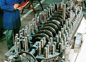
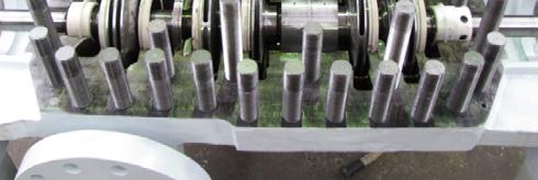
Reconditioning
Restor e Clear ances
Re- Engineering
P f T ti erfor mance Testing.
Services available include:
• Inspection and trouble-shooting
• Case build up and re-machining
• Aillitfid bi Axial split case facing and reboring
• Axial thrust balancing
• Shaft and bearing API 610 upgrades
• Mechanical Seal upgrades to API 682
• Bearing housing & back cover retrofit
• Lube system upgrades
• Composite Wear Parts
• Tighter clearances
• Hydraulic Re-Rating
• Ridtti Rapid prototyping
• Driver upgrades (MEPS compliance)
• Baseplateadaptors and rebuilding
• Custom Spare Parts
• Rotating Element balancing
• ASME & AS1210 qualified Welding
• Hydrostatic Testing
• Performance Testing
• FFT Vibration







The PIA was saddened to hear of the passing of Life Member Arthur Feiner in January 2015, aged 92 years.
Arthur joined Harland Engineering Australia to further the hydroelectric business, and subsequently became a director of the company. He was considered to be a very talented engineer and manager.
On receipt of his life membership, Arthur made a very gracious and interesting speech, however in later years the PIA sadly lost touch.
The Hydraulic Institute has named Weir Minerals Manager of Research and Design Aleks Roudnev as its 2014 Member of the Year. The award was made at the Hydraulic Institute’s 2015 annual meeting, held recently in St. Petersburg, Florida.
The Hydraulic Institute Board of Directors selected Mr Roudnev
for his superior commitment to the Hydraulic Institute in both leading and actively participating in numerous committees in the advancement of the Institute’s technical work. They also recognised his work in guiding young engineers within the Institute’s extensive technical organisation.
As an active member of the Hydraulic Institute since 1995, his recent contributions include serving as Chair of the Standards Committee, the Slurry Pumps Committee, and he serves as Vice Chair of the General Guidelines Committee. Mr Roudnev has distinguished himself for the level and extent of his involvement, thus advancing the technical work of the Hydraulic Institute on many levels.
As expressed by many members, his wisdom is appreciated by the committees which benefit from his participation. Further, he has provided support to develop and enhance the language used in standards and guidelines, and he has been instrumental in improving the clarity and precision which is necessary for ANSI/HI standards.
The Hydraulic Institute has also appointed a new Executive Director, Michael B. Michaud.
“On behalf of the entire Board I am very pleased to welcome Michael Michaud as HI’s new Executive Director,” said George Harris, Chairman of the HI Board.
“Michael’s talent and international experience will be invaluable to us as we develop and implement strategies to continue the growth that we have experienced under the leadership of Bob Asdal and the HI staff”, he said.
For the past 19 years, Michaud has held various leadership roles at the American Society of Mechanical Engineers (ASME) where he currently is Managing Director, Global Alliances, responsible for ASME’s Global Strategy Execution and International Business Development primarily by growing an extensive network of Global Partners.
Prior assignments included managing several business areas including ASME’s Training and Professional Development portfolio, ASME’s Gas Turbine and Petroleum Technology Institutes as well as outreach and support for ASME’s international membership.
At Pump Industry, we love our readers, and we love to see photos of you reading our magazine. To encourage you all to share a photo of yourself reading your favourite magazine at your workplace, we’re giving away a copy of the Australian Pump Technical Handbook for the best pump reader selfie.
Entering your selfie is easy – just take a snap of yourself reading Pump Industry (or feel free to ask someone to take the picture for you), then either send it to Managing Editor Laura Harvey or tweet it and tag @pumpmag with the hashtag #pumpupyourselfie.
The best picture, as judged by Pump Industry, will receive a copy of the Australian Pump Technical Handbook, the Australian pump industry’s one-stop guide to all things pumps, valued at $90.
So get creative and share your snaps today. Along with the selection featured in this issue, we’ll continue to publish the best entries in the magazine and on our website – so now is the chance for you to get in front of all your pump industry colleagues, clients, and friends.
Some of the #pumpupyourselfie entries we’ve received so far. Alwyn Henriques of Flowserve (top) and Jane Waters of United Pumps (below).




The pump industry relies on expertise from a large and varied range of specialists, from experts in particular pump types to those with an intimate understanding of pump reliability; and from researchers who delve into the particulars of pump curves to experts in pump efficiency. To draw upon the wealth of expert knowledge the Australian pump industry has to offer, Pump Industry has established a panel of experts to answer all your pumping questions.

Our progressive cavity pump expert is Peter Vila, Managing Director of SEEPEX Australia. Peter has been involved with pumps for 35 years. He spent the first five years repairing them and the subsequent 30 years directly in technical sales, and for the past 15 years he has been predominately involved in one way or another with seepex progressive cavity pumps.
Has there been a study carried out on whole-life costs of progressive cavity pumps in comparison with other positive displacement technologies?
The short answer is ‘not to my knowledge’ – but it would certainly be interesting to see the results of such a study. By design, progressive cavity pumps have always been considered a high wearing item with maintenance costs exceeding most other pump designs. A major contributing factor to this perception has been the applications for which progressive cavity pumps are often used, typically non-flowable and sometimes abrasive products, the progressive cavity pump can at times be the last option, when
no other pump will do the job.
But with careful consideration, it is possible to confidently utilise progressive cavity pumps which can provide the user with considerable whole-life cost savings.
Special care must be taken when selecting pump speed and materials, giving due consideration to pumped media – viscosity, solids content and abrasiveness. It’s quite common for the uninitiated to select inappropriate materials, or a smaller pump running faster, with a view to saving a few dollars on the initial purchase, only to find their maintenance costs have soared out of control due to an inappropriate pump selection. The important thing is to ensure you have the necessary information and experience to make a confident selection, or failing this, you have the contact details from a reliable source and seek their assistance.
Some progressive cavity pump manufacturers now have ‘maintenance friendly’ designs, which can offer significant savings in downtime, labour costs and spares prices, thereby reducing whole-life cost.
There are also some progressive cavity pump designs which have an adjustable clamping feature between rotor and stator. In many cases it is possible to relax the clamp when maximum pressures are not required

The SEEPEX app which calculates whole-life cost savings for pumps.
and the result can be a reduction in power requirements, which again can significantly reduce whole life cost, especially when the pump is coupled to one of the latest model, high-efficiency drive designs.
I believe a number of progressive cavity pump manufacturers have apps these days to assist their customers in calculating whole-life cost savings for their pumps. I know my company, SEEPEX, has such an app for the SCT design and anybody can download this free from the Apple App Store or Google Play.
A simple search for either SEEPEX or SCT will locate the free download and I’m sure similar searches for other brands or models will also achieve similar results. Happy searching!
For more information on progressive cavity pumps, please contact SEEPEX Australia on (02) 4355 4500 or info.au@seepex.com.
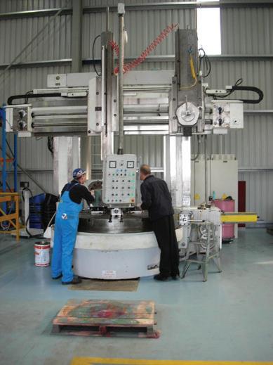
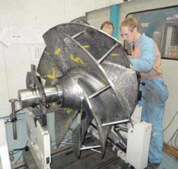
Engineered Pump Rebuilding
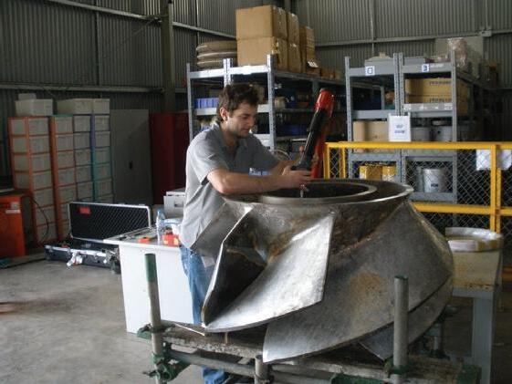
Since 1969, Hydro has built its worldwide pump service organization by bringing a high level of engineering expertise and quality service to the pump aftermarket. Hydro Australia works with our customers to evaluate and understand the root causes of pump degradation or failure and to provide unbiased engineering analysis, quality workmanship and responsive field service for improved plant operation.
Certified Service Centre

Hydro Australia has always been committed to Quality and Occupational Health & Safety. Hydro Australia holds the AS:NZS ISO 9001:2008 certificate in addition to the AS:NZS 4801 and AHSAS 18001 certificates.
Turnkey, Field Service and 24/7 Emergency Response
Hydro Australia’s Field Service team has extensive knowledge of pumps from most major manufacturers and provides turnkey service, installation / start-up supervision, field machining, vibration analysis, laser alignment, pump system troubleshooting and emergency field response 24 hours a day, 7 days a week.
Pump Parts
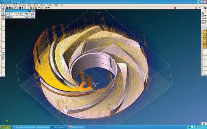
When you require a part and are facing a long lead time, Hydro Australia can meet your needs in a reduced time frame through our reverse engineering, patternless casting and integrated manufacturing processes. Hydro's engineers review and evaluate all parts to offer important upgrades and apply new technologies that will reduce wear and improve reliability.
Pump Testing - Managing Risk
Ensure your pump will perform as required. Hydro’s 5000HP Performance Test Lab, located in the United States, is compliant to API610 and Hydraulic Institute standards and can test horizontal, vertical, and submersible pumps.
Training
Hydro teaches practical solutions and troubleshooting techniques for common pump problems and offers specialized hands-on training programs. View upcoming courses online at www.hydroinc.com.
Call Hydro Australia at (03) 51650 390 with your pump service inquiries or contact Ross Bertolimobile: (0418) 581190 email: ross@hydroaustralia.com.au.
PIA President Ron Astall recently travelled to St Petersburg, Florida, to attend the Hydraulic Institute’s AGM and Conference, representing the Australian pump industry on the global stage.
In 1991 the Hydraulic Institute was a volunteer organisation of pump companies with a solid background of generating some basic pump and pump testing standards. In many respects it was an organisation very similar to PIA only a couple of years ago.
At that time they appointed a full-time Executive Director, Bob Asdal, and under Bob’s guidance, the Hydraulic Institute has since grown into an impressive organisation with around 16 full-time staff. Late last year, the Hydraulic Institute’s Ross Bertoli rang me and asked if I would like to meet his boss, George Harris, the President of the Hydraulic Institute.
George was a charming gentleman and bemoaned the historical lack of involvement between the Hydraulic Institute and the PIA. We both agreed that this needed to change and subsequently I was invited to the Hydraulic Institute Annual General Meeting in February.
With the generous support of PIA, I headed to St Petersburg, Florida. I will be providing a detailed report on the PIA website, however a number of observations are worth relating here. This conference of 265 delegates was easily the most professionally run event I have attended. All the minor details
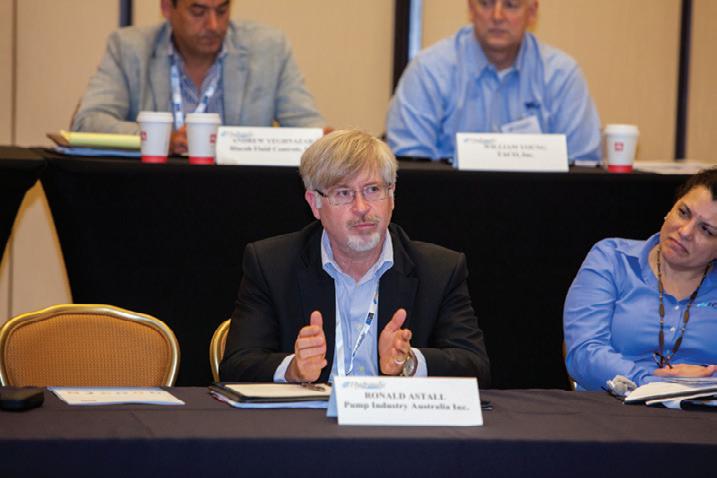
were taken care of, even to the extent of a personalised email reminder every evening re-confirming my itinerary for the following day.
The meetings themselves were mostly addressing the upgrading and re-writing of the Hydraulic Institute’s standards and guidelines. Comment was welcome from all attendees, whether they were formal committee members or not.
Along with Standards and Guidelines, the Hydraulic Institute is very active in Pump System Optimisation (PSO)
training and, like the BPMA, they are developing a certified pump system auditor training program.
These energy efficiency initiatives are probably the Hydraulic Institute’s key activities at the moment and they have gained solid support and sponsorship from a number of the big utility companies in the US and the Northwest Energy Efficiency Alliance.
There are currently $US9 billion dollars available in energy efficiency programs in the US and a number of the power
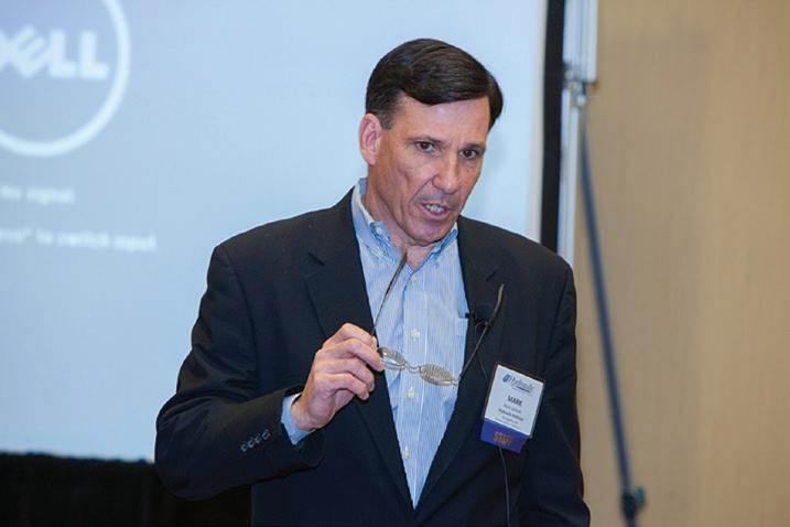
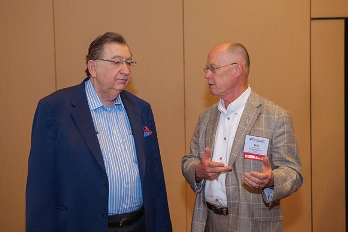
supply companies have subscribed to the Hydraulic Institute’s PSO program. Along with the technical stuff there were presentations on leadership, emerging technologies, and on economic topics.
I discovered that Australia is globally ranked seventh in average wages at $US48 per hour, compared to Japan, the US and Canada at $US35 per hour. India was $US1.50 per hour and China $US3.20 per hour. Despite being ranked seventh in wages cost, Australia has the world’s highest manufacturing cost; at around 30 per cent above the US.
The good news (for those of us selling to the resource industries) was that the oil price should recover to $US85/ bbl and China’s demand for resources should recover around the end of 2016; with Australia expected to be the major beneficiary.
The Hydraulic Institute sees itself primarily as a marketing organisation whereby their standards, guidelines and training initiatives can be utilised by their members to generate strong customer relationships. Following my discussions with the Hydraulic Institute team I am confident there are a number of areas where a relationship with PIA will be able generate mutual benefits; such as in marketing of publications and sharing training programs.
Certainly it was an inspiration meeting the ‘Rock Stars’ of the global pump industry, and to see how the Hydraulic Institute go about their business.
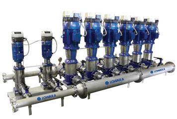
• Motor or wall mountable
• Fully programmable on site
• Software specifically designed for pump operation, control and protection
• High level hardware design
• More flexibility and cost savings
• Energy savings up to 70%
• Simple mounting “clip and work”
• Multi-pump capability up to 8 pumps

Ph: 1300 4 BBENG

The PIA is in the process of finalising a new training course, which will fill a need in the industry for quality information and training on the installation and commissioning of pumps.
The Installation and Commissioning course will be designed to a high standard, with a view to having it accepted by pump manufacturers and suppliers, contractors and end users as the qualification required to supervise the installation, and carry out the commissioning of pumps.
The course will comprise three sections. The first section will take place in a classroom environment, and it will cover how pumps are installed, including concrete base construction, erection of the pump set, installation of the suction and delivery pipes and aligning the pump set prior to commissioning. The first section will also cover the commissioning of both electric and engine driven pumps, including personnel requirements, tool requirements, pre-start checks and procedures, pump set starting, commissioning run, how to estimate the pump duty in relation to the system curve, troubleshooting during commissioning, pump shutdown,
record keeping during commissioning and signing off on completion of commissioning.
The second and third sections of the course will be practical – one covering electric driven pumps and the other covering engine driven pumps. Both these sections will take students through the commissioning process for the two types of pump set, including preparation for commissioning starting, running and stopping the pump set and keeping the required records. The practical will also cover troubleshooting and duty estimation.
The course will be designed so that each section will take half a day, and the participants will be tested at the end of each section and a pass will be required at each section for the successful completion of the course. In order to ensure that each participant gets the instructor’s full attention, each course will be limited to ten participants. The classroom aspect of the course will be conducted using powerpoint
presentations with each participant receiving comprehensive course notes. At this time preparation of the course notes and powerpoint presentation is well underway. In order to be sure that what has been produced meets industry needs, PIA will conduct a ‘dry run’ session of the classroom part of the course, with time allowed for feedback from those attending on content and presentation.
PIA would like as many interested parties to attend as possible, so we can cater the course to meet the industry’s needs. There will be no charge for attending this ‘dry run’ and the details are as follows:
Bruce County Hotel 445 Blackburn Road Mt Waverley 3149
23 June 2015, 1-5 pm
Anybody wishing to attend this preview of the installation and commission course should contact Kevin Wilson at pumpsaustralia@bigpond.com.
The next PIA General Meeting will be held in Adelaide on 12 May, with the meeting to be followed by a two-course dinner. Come along to network and reconnect with clients, colleagues and friends.
The PIA Council is heading to Adelaide in May for its second general meeting of the year. Along with the chance to hear about all of the PIA’s activities for the year thus far, attendees will also have the chance to enjoy a two-course dinner with South Australia’s pumping elite. During the general meeting, attendees will also enjoy presentations from PIA President Ron Astall and PIA Marketing and Statistics Executive Officer Keith Sanders.
Ron will pose the question ‘Are your pumps running too slowly?’ and provide informative insights on the topic. Ron will also discuss his visit to the recent Hydraulic Institute conference in the US.

Keith meanwhile will deliver a presentation on the ‘Basics of good pump selection’– a must-see for anyone active in the industry.
The general meeting and dinner will both be held at the Rydges South Park, located at 1 South Terrace Adelaide. The meeting will take place from 4.30-6pm, with complimentary drinks to follow, before dinner in the hotel restaurant.
The restaurant offers views across the Parklands to the Adelaide Hills, and the company of all your pump industry colleagues and friends. The cost for the dinner is $75, which includes a two-course meal and beverages.


Register your intention to attend the meeting and the dinner with PIA Secretary Kevin Wilson at pumpsaustralia@bigpond.com.
PIA Adelaide General Meeting
Rydges South Park, 1 South Terrace Adelaide
Tuesday 12 May 5-6pm
Complimentary drinks to follow
Join us after for a two-course dinner for just $75 per person


SEEPEX Smart Conveying Technology extends the life of your stator. Adjustment of the retaining segments takes just 2 minutes and restores 100% pump performance.
Tests have shown up to 3x stator life compared to conventional progressive cavity pump design Join the smart revolution and test our innovation “Smart Conveying Technology”.


SEEPEX Australia Pty. Ltd. Tel +61.2.4355 4500

Whether it be a household pump, a pool pump, or a specialised engineered product for a specific application, Pentair has you covered.
New products are on the way in 2015, with Everflow models offering better efficiency, less stages, and reduced power requirements in many cases. Pentair Southern Cross is increasing stock holdings of components to provide improved delivery.
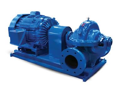
Aurora horizontal split case units now supplement the Southern Cross Centurion range. These are available as Aurora 410 standard product or UL/FM approved.
The new Commercial WaterSwitch is also now available, incorporating the market leading Onga WaterSwitch coupled with the reliable Southern Cross PVMI5-10 vertical multistage pump. There is no pre-assembly of system required – it’s just ‘Plumb & Play’. Available in either single or variable speed, the systems are both economical to run, while taking advantage of rainwater harvesting for both non-potable building services facilities and irrigation.
Kelair Pumps Australia CEO John Inkster said “We are very fortunate to have someone of Steve’s calibre take up this role. His considerable industrial experience and diverse background in all facets of the pump industry means he is ideally qualified for this position.”
Steve started in the pump industry at Kelair in 1988 and spent five years in internal and external roles before leaving to broaden his experience. Since returning to Kelair in 2006 Steve has held the roles of Industrial Sales Manager and National Sales Manager. Steve took over as General Manager in November 2014.
In the years between his time at Kelair, Steve had three years as National Projects Manager at what was then ITT Flygt, and before that several roles at Weir Warman, spending a total of nine years there, split between WA and their Artarmon facility in NSW.
Steve also spent some time doing contract engineering work, mostly in the mining industry.
Steve said “I am looking forward to the challenge of the new role and building on the legacy started by Bill Smith in 1975 and built on by Tony Sgro after the sale of Kelair to Brown Brothers Engineers Australia in 2004.”
Pentair Onga has welcomed Kohler diesel driven pumps to the firefighting range. The B48K Blazemaster pump offers max flow rates to 500LPM and up to 500kPa. The direct injection system produces increased power and lower fuel consumption. The KD225 diesel engine delivers the performance engineering standards you’ve come to expect from Kohler.
Jung Pumpen, Pentair’s premium wastewater handling systems
Jung Pumpen is a brand that stands for high quality and its continued growth within the Australian market can undoubtedly be attributed to its world class German engineering.
Pentair look to extend the range further to include the wastewater pumps for both domestic products and larger-scale commercial wastewater treatment.

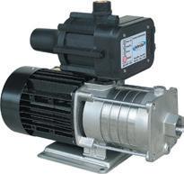
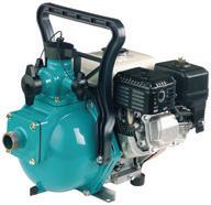
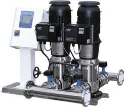

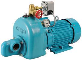


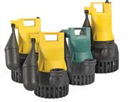
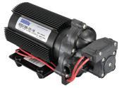
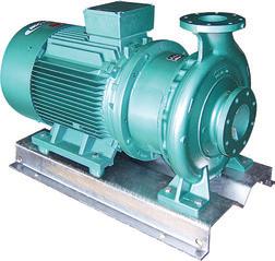
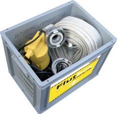
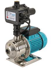
The world’s largest manufacturer of submersible pumps, Tsurumi Manufacturing Company, has the capacity to build over 1.4 million pumps a year. The company, constantly looking to improve efficiency and drive down costs, has recently expanded and consolidated production of its range of single phase pumps to a single manufacturing facility.
The new factory site covers 6,620m2 and is capable of building over 400,000 units annually. The company’s investment in state-of-the-art equipment and streamlining of production methods means the four main production lines can produce over 1,600 pumps in a single day.
“I was lucky enough to visit the new plant last month and was so impressed with the organisation and automation of this world class facility,” said Australian Pump’s Hamish Lorenz. “Tsurumi run a vast automated component storage system which is controlled by a single employee. It maximises efficiency which means huge cost savings for distributors and end users.”
The partnership between Australian Pump and Tsurumi brings Australian consumers top quality product, backed by first class aftermarket support right throughout the territory. Tsurumi Pump was founded in Osaka in 1924. Most of the company’s manufacturing is carried out in a plant in Kyoto in Japan, where the most advanced Computer Integrated Manufacturing (CIM) systems are used. This roboticised operation can build over one million pumps a year.
Tsurumi’s commitment to quality and value for money has made them world leaders in pump markets, ranging from construction through to wastewater management.
The single phase submersible range include residue dewatering pumps that pump down to the last millimetre, standard and automatic dewatering subs, together with a range of sewage and effluent handling pumps.
Australian Pump has been quick to pass on the savings generated by improved efficiency. Since taking on the Australian distribution of the Tsurumi product, prices on the single phase range have been reduced by over 40 per cent.
“Tsurumi understands that competition in the lower end of the submersible pump market is immense. Cheap third world pumps are flooding into our country, but the quality often leaves consumers disappointed and inconvenienced. Tsurumi offer a threeyear warranty on their submersibles and customers are intelligent enough to understand that there’s more to value than price alone,” said Mr Lorenz.
Australian Pump operates from a two-and-a-half acre head office complex in Sydney’s Norwest industrial area. The company is a rising star in pump manufacturing and distribution in Australia, with a heavy emphasis on servicing the mining, construction and heavy industrial markets.
“Our own in-house manufacturing operation, building engine drive pumps and pressure cleaners, is only small in comparison. Nevertheless, there are a number of simple ideas I’ve brought back that will help us benefit from Tsurumi’s expertise. We are learning production techniques from one of the best in the business,” said Mr Lorenz.
For further information on Tsurumi submersible pumps, contact Australian Pump Industries distributors throughout Australia, or check the website
“Tsurumi run a vast automated component storage system which is controlled by a single employee. It maximises efficiency which means huge cost savings for distributors and end users.”


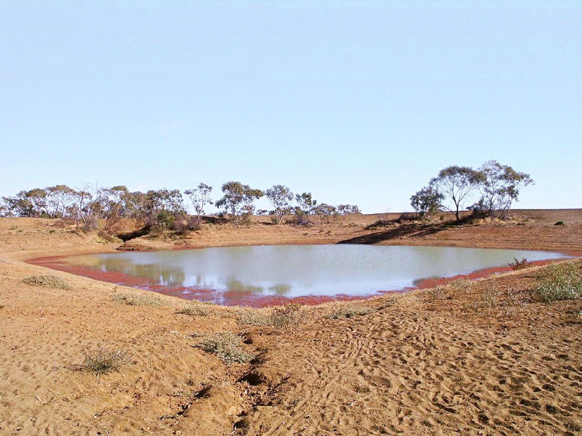


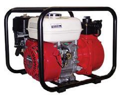





In any industry it is important to have a reliable supply chain – it is often a critical factor of success in meeting your customers’ expectations.
We operate in a globally assimilated world. As a result we find that the combination of business carrying lower inventory, and the expectation of timely deliveries on short notice, means supplier dependability is fundamental to business success.
It is not only up to the supplier to be reliable, but as a purchaser we must also prove to be consistent. The more predictable we become, the more our suppliers can correctly plan on ensuring our requirements are met. If we can forecast our demand we can then project what we require from our suppliers, which allows them to prepare for the demands of the industry.
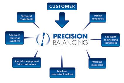
At Precision Balancing we believe it is also important that we diversify our supply position to maintain our customer service levels. We provide a diverse range of industrial services, and therefore manage a wide portfolio of partners in our supply chain, including design engineers and technical consultants, specialist material suppliers and equipment hire
contractors, specialist engineering companies, machine shops, welding inspectors and tool makers.
It is imperative that we remain resilient and always expect the unexpected, and be prepared to respond proactively to any situation. Sometimes it is necessary to create a dual supply for parts and raw materials, so that if one supplier is unable to meet our requirements, the other can assist.
We also believe it is important to develop trust with our suppliers, and not to overload them and create an unmanageable workload, or set unrealistic deadlines. Their business is important too, and we want to see them be just as successful. We have to
be equitably transparent with them and offer them correct information which will then enable them to respond to our needs appropriately.
Any company is only as strong as its weakest link, and as a supplier, our customers depend on our reliability. In order to meet the demands of our customers we therefore become dependent on our suppliers’ ability to meet our demands, and so it goes on. That’s why at Precision Balancing we believe it is integral for any business to invest in a reliable supply chain, and to manage it proactively to ensure the best results for your customers and suppliers.
Precision Balancing has been offering in-house and on-site dynamic balancing and vibration analysis services since 1989 and has the equipment, skills and experience to satisfy your industrial balancing requirements. For more information on industrial balancing services

ABB has launched a new, highly efficient drive package for low-speed vertical pumping applications with high power requirements.
ABB’s new drive package, the Dodge® Vertical Gearmotor, is built on a standard low pole count motor platform, utilising proven, highly efficient Dodge® planetary gear technology.
The Vertical Gearmotor offers significant benefits, especially compared with common pump drive technologies that utilise large pole count motors, which can be large, expensive, and often result in a drastic reduction in efficiency and power factor.
“Lower pole count induction motors offer higher efficiency ratings and power factor versus high pole count induction motors,” says Mike Myers, ABB Global Business Manager for Dodge® specialty and large gearing. “A higher power factor equates to more efficient use of electrical power and less reactive power drawn by the system. Not only are lower pole count motors more readily available, they also offer a significant cost saving opportunity over high pole count motors.”
Utilising the reducer to accommodate thrust load is also more cost effective than designing this functionality into the motor. The smaller footprint and lightweight design of the Dodge® Vertical Gearmotor in comparison to traditional pump drive systems also translates into further cost savings due to the reduced support structure and corresponding facility costs.
Beyond cost savings, the Vertical Gearmotor also provides maximum pump performance. By using the specific gear reduction ratio required for a specific application, optimised pump speeds can be attained.
“Being able to provide the exact output speed means you can lower vibration levels, decrease radial and axial loads, and create optimal discharge pressure,” said Mr Myers. “This efficient design also results in improved reliability and reduced maintenance.”
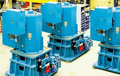
The Dodge® Vertical Gearmotor.
The Dodge® Vertical Gearmotor is ideal for a wide range of pumping applications, including pumping stations for flood control and wastewater, circulating water in power plants, desalination plants, irrigation systems, and pumping systems for residential and commercial water supplies.
The product is available in six sizes, for vertical pump speed from approximately 100-500RPM, and torque ratings from 62,000-790,000Nm, and approximate power ratings from 600-22,000kW, depending on system output speeds.

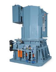
The Dodge Vertical Gearmotor provides an alternative to common vertical pump drive technologies and offers significant benefits when compared to other systems. The Vertical Gearmotor is built on a standard low pole count motor platform utilizing proven Dodge planetary gear technology. This results in a smaller, lighter, more cost-effective and highly efficient package.
www.abb.com/mechanicalpowertransmission
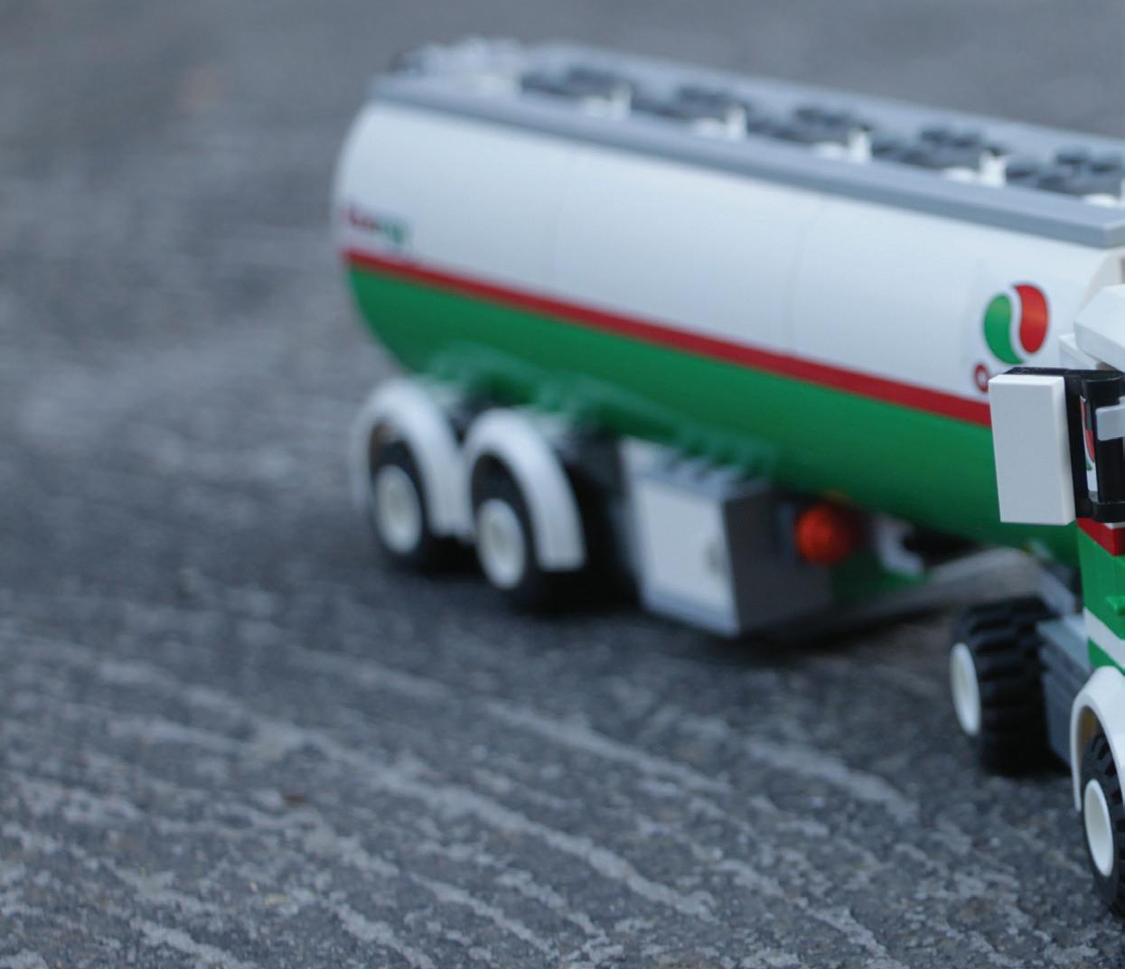
Fuel delivery trucks, tank trucks and mobile trailers all have the task of handling and metering fuel. The major challenge for all of these is avoiding loss of product, time and money.

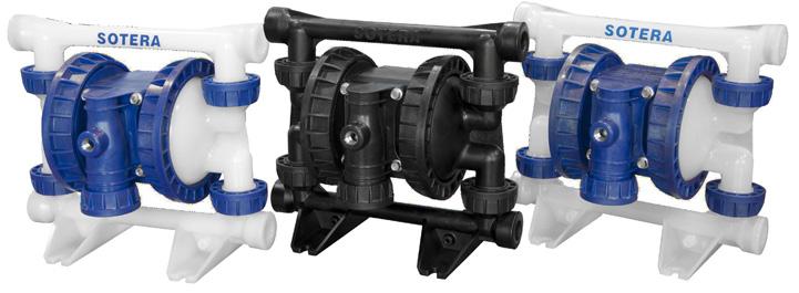

High quality equipment is required for the efficient performance of petrochemical transport, which includes pumps, meters and hydraulic coolers. Hurll Nu-Way offers high quality equipment from leading manufacturers, being a one-stop shop for your mobile fuel applications.
Petrochemical tankers and mini tankers typically use pumps mounted directly to the bottom of the tank, or foot-mounted pumps mounted on the chassis of the truck and piped to the bottom of the tank. The best technology option for this type of transport is sliding vane. These pumps are driven either by a PTO connection coming from the truck’s engine or by a hydraulic motor direct mounted to the pump. There would be a
hydraulic pump system mounted on the truck to drive the motor on the pump.
Hurll Nu-Way offers a range of sliding vane pumps including Corken PT, PZ and Coro-flo series. Available in most sizes, they are characterised by high pumping efficiency, low noise, and thrust bearing design for durability, with a hydraulic drive option. They are available in foot and truck-mounted designs for versatility and are easy and cost effective to maintain.
The trucks are also equipped with meters that measure the amount of product being dispensed for point of custody transfer and/or for billing purposes. Hurll Nu-Way offers a variety of metering technologies for the mobile petrochemical industry. When it comes
to LPG, Hurll Nu-Way offers the only truck-mounted mass flow meter in the market, with over twelve years of proven performance. Introduced in 2002, the world’s first mass flow meter designed to meet the rigorous demands of the LPG bobtail/tanker environment, the Neptune/Red Seal mass flow meter is highly accurate and virtually maintenance free.
A mass flow meter utilises Coriolis effect and provides volumetric flow measurement of propane gases when interfaced with a Liquip electronic register. The addition of Modbus allows a direct measurement of mass, density and temperature. The outstanding flexibility of the Liquip register gives the system an upgrade path not obtainable with competitive electronic transaction management systems. The Liquip menudriven register functions are easy to learn and remember.
Interfacing through common handheld devices and laptops makes data management fast and easy between truck and office. The space-efficient Neptune RML2000 system can be installed on both new and existing vehicles.
The third component contributing to the performance of a mini tanker is a hydraulic oil cooler, combining the functions of an oil tank, oil cooler and security relief valve.
Hurll Nu-Way offers the HydraFlow hydraulic oil cooler, featuring a downward facing fan for quieter operation. Ranging from 21-28cm, these units can be mounted in tight installations, and bring the benefits of maximum efficiency and minimised filter damage with filter bypass valve.
With high quality equipment, your truck is ready to go. If you handle propane, butane, LPG, carbon dioxide, lube oil and other hazardous liquids and gases, contact Hurll Nu-Way to learn more about the solutions they offer.
Pump reliability expert Ross Mackay shares his thoughts on pump failure, which come back to two simple ideas: most pump problems have very practical solutions; and repetitive failure can be stopped.
Over the last 25 years of a much longer career in pumps, I’ve been given the privilege of training tens of thousands of engineers and technicians in pump reliability. This has provided me with the opportunity to hear the problems of that same number of pump users in the same period of time.
From this experience I’ve learned three things:
1. Most pump problems are very practical
2. The solutions are also very practical
3. Repetitive pump failure can be stopped.
To most of you, the first of these comes as no surprise, because you’ve been living with some very practical issues yourself, such as: my pump isn’t delivering enough water; it doesn’t matter what seal I use, it fails every three months; we can’t seem to stop the cavitation; and so on and so on.

It’s the second two that may offer some surprise. Particularly if you are in the kind of plant where repetitive pump failure is causing ongoing problems like lost production, expensive downtime, environmental difficulties, and excessive maintenance costs; but it really is true. Most pump problems have very practical solutions and repetitive failure can be stopped.
So why do so many companies live with a pattern of repetitive pump failure? Well, in my experience, it usually means one of four things:
1. They don’t know how to prevent their pump problems
2. They’re not willing to do what’s necessary to prevent the pump problems
3. They don’t think it’s possible to prevent their pump problems
4. They don’t want to prevent their pump problems.
We won’t waste any time on the last group, other than to say that it does exist. A millwright in one particular plant
told me quite openly that pump failure was sending his kids through college by means of the overtime it gave him. Consequently, he wouldn’t be trying too hard to prevent it!
As for our other categories of people living with repetitive pump failure:
• The first group don’t believe it’s possible to prevent the pump problems because, if it were true, somebody would have done it before now. A sad but not uncommon attitude.
• The second are not willing (or able) to commit the resources to make the necessary changes to eliminate the problem. Occasionally this can be a real budget problem, but all too often it’s a result of short-term thinking.
• Finally, for the third group, not knowing how to prevent pump failure is simply a matter of not having the necessary information. There’s no shame in that; the only shame lies in staying that way.
The reality is that, in many plants, not having the information is normal, because nobody gave it to you. That’s why so many people think that their problems are inevitable and can’t be prevented. That is not true!
The problem is frequently ‘on the job’ training. Or, if we can be more honest with each other, ‘picking it up as you go along’. What little training that does exist is usually limited, frequently inaccurate, or is provided by the pump manufacturers who generally focus on how to take the pumps apart and put them together again. This is usually referred to as ‘hands-on’ training, yet most millwrights can do this extremely well, simply because they’ve had to do it so frequently!
Hands-on training is very popular because everyone (including the maintenance department) just knows that the pump failed again because maintenance did something wrong the last time they fixed it. Or did they?

If that is the case, consider these five important questions:
1. Which two pump parts are the most technologically advanced?
2. Which two pump parts are not covered by a warranty?
3. Which two pump parts are not manufactured by the pump company?
4. Which two pump parts are the ones that fail most frequently?
5. Why?
While anyone who knows their way around a pump can answer the first four questions, it’s the last one that causes some hesitation, and no wonder. The seals and bearings in most pumps act in a manner similar to the fuse in an electrical system. To a lesser degree, exactly the same thing will happen with packing. Just because the fuse fails, doesn’t mean there is anything wrong with the fuse. In fact, most of us understand that the problem is almost always somewhere else. However, when a seal, packing, or a bearing fails, instead of looking somewhere else for the problem, we simply replace the offending part, reassemble the pump, and start up again.
In other words, we reinstall the same problem, and can expect to deal with it again, and again, and again, throughout the life of the pump.
So how do we break the cycle of failure?
Well, one thing we shouldn’t do is keep doing what we’ve been doing up until now. It’s been said that the most prominent example of insanity is to keep doing what you’ve always done, but to expect different results. That doesn’t work in the pump business any more than it does anywhere else in life.
Nor do we try about four or five different things at the same time, because if any of them do work, we still don’t know which one was effective; preventing our ability to repeat the success elsewhere.
Simply put, we can try and figure out
where the real problem is and fix it. This is frequently referred to with the grandiose title of Root Cause Analysis, but let’s not get too fancy with either the words we use or the things we try.
The reality is (and I probably shouldn’t admit this publicly as it could affect my consulting business) that this pump business is not really as complicated as many would have you believe. The only really difficult area is in designing the pump in the first place. Once you have it in your plant or mill, all you have to do is operate and maintain it within certain preset parameters and there’s no problem. If I’m ever accused of being too simplistic, I will happily plead guilty, because for every pump problem you will ever experience, I believe there are only six possible solutions. So, repetitive pump failure really is the unnecessary evil in almost every process.
Ross Mackay is internationally recognised as a specialist in pump reliability, specialising in helping companies increase their pump reliability and reduce operating and maintenance costs. He is the author of the industry best-selling textbook The Practical Pumping Handbook and can be reached at +1 905 726 9587 or through his web site at www.practicalpumping.com.


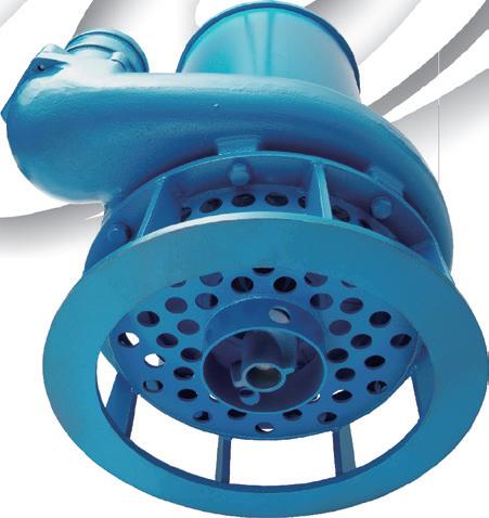
Specialist metallurgy business, Advanced Interactive Materials Science Limited (AIMS), has successfully manufactured a Venturi Valve using HIPed powder metallurgy and near-net shaping techniques.
Used to measure the flow of oil and gas as it comes out of the ground, Venturi Valves need to withstand extreme conditions and meet stringent oil and gas industry subsea standards.
The Venturi Valve is another cuttingedge component for the oil and gas industry from AIMS. Last year the UK-based company unveiled a patented mud motor stator (featuring a telemetry hole) that can resist corrosive, erosive and abrasive conditions at high operating temperatures.
AIMS Technical Director Geoff Archer said: “Replacing Venturi Valves is a difficult and costly process, so producing components with high quality isotropic material structures that reduce manufacturing risk and maintenance costs is something the industry is keen to exploit.


“We believe we have accomplished this with the Venturi Valve, which has exceeded all technical test results to date. It’s extremely exciting and initial feedback from the oil and gas industry has been positive.”
There is growing demand for HIPed and near-net shaped products due to the efficiency of the process and the quality of the component. However, the mechanical properties of the end result have to meet specific international standards, and until now this has not always been achieved.
The AIMS product, when tested, revealed that it had zero argon ingress during the hot isostatic pressing process.
For more information on the Venturi Valve, visit www.aimsltd.com.
“This is an outstanding result, as it has overcome one of the major problems for the industry. It highlights the high quality standard of our powder containments and HIPing capabilities which, when coupled with near-net shaping techniques, minimise the need for second stage machining,” explained Mr Archer.
At the cutting edge of manufacturing technology, near-net shaping delivers savings in terms of energy, materials and labour, whilst allowing complex structures to be created, such as the Venturi Valve and the mud motor stator with telemetry hole.
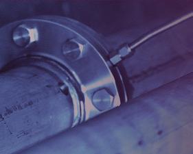


Pump reliability is a challenge all pump end users face. Here, Randal Ferman shares his experience in improving reliability and ultimate life cycle in modern pumping systems.
Approximately 30 years ago, I skimmed through an exhaustive study of the possible modes by which a prototype nuclear pump could fail and the probabilities connected with these events. In the report, the first reliability study I had seen, there was no discussion on how to influence or change failure probabilities. Without any linkage to changing real outcomes, I was left with the impression that reliability was little more than an academic exercise.
Years later I came to realise that reliability has operational and financial consequences and encompasses much of the life cycle of a pump, beginning with equipment selection and continuing on through operation and maintenance and, as applicable, through modifications of the process and the machinery.
As depicted in Figure 1, the scope of
reliability is a composite of how the pump is designed, manufactured, and assembled; how it is installed; the product being pumped; the pump operating conditions; condition monitoring; and maintenance practices. The whole point is missed if one considers pump reliability as somehow detached from all of the activities that conceive, create, operate, and maintain a pumping installation.
Arguably, the greatest technical challenge facing manufacturers and users of pumps is improving reliability. Mechanical seal leakage gradually or exponentially increases to an unacceptable level, seemingly without cause. Bearings fail, often with little advance warning; when bearings fail this can wreck the mechanical seal and a whole lot more. Pump internal clearances, subjected to pressure and erosion, wear out, amperage draw goes
up, and pumping performance falls off. Shafting and impellers fatigue and break. Flanges leak, gaskets blow. This is all familiar to those who operate and maintain pumps. Is it all kismet, or can we be agents of cause over the future of a pump?
Usually a pump ‘fails’ due to the failure of a single component. Moreover, depending on how promptly the pump is shut down after initial symptoms of imminent failure appear, other components may be damaged as well. Depending upon trends in vibration, leakage, power consumption, loss of performance or other indicators, the pump’s symptoms are telling us with some degree of predictability how soon it should be pulled out of service for repair. The less forewarning, the greater the impact of lost production and pump repair costs.
Repairing the pump brings it back to
operational status, but this action alone may not improve reliability. The root cause of pump premature failure may be operating continuously at an excessively low flow or an excessively high flow; some sort of machinery dynamic problem resulting in excessive vibration; excessive piping loads; cavitation, coupling or rotor imbalance or shaft misalignment; a mechanical seal or bearing overheating problem; and other possibilities. In such instances, finding and fixing the root cause brings about a dramatic improvement in the pump’s mean time between failure (MTBF).
A pump includes both stationary and moving parts that can fail. Usually stationary pump components are not the cause for pulling a pump out for service, but rings and bushings do wear and occasionally static seals or gaskets leak. Also, pump casings can become excessively worn or corroded but seldom cause in-service failure. It is often quipped that a centrifugal pump has a single rotating part. But actually, considering the mechanical seal and bearing assembly, there are some two or three dozen moving parts, any one of which can fail and take a pump out of service. In order of frequency, the most common pump components that fail are mechanical seals, bearings, couplings, shafting, and impellers.
Excessive leakage of the mechanical seal is the most common reason why a pump is taken out of service, if even for just a few hours to install a new seal or remedy the specific leakage issue. There are many possible reasons and scenarios leading to excessive seal leakage. Mechanical seals are precision devices that demand careful handling
Conditions of service
Equipment selection and specifications
Design drawings, analysis, detail specifications
Design review

Scheduling and procurement
Material processes
Inspection and quality control


Assembly, test and packaging & shipment
Anchors, baseplate and grouting
Piping and wiring

Drive train alignment
Commissioning


Procedures
Surveillance


Figure 1. The scope of pump reliability.
and installation procedures. The sealing gap between faces for liquid seals can vary between five and 50 micro-inches
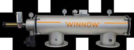
• For use in Irrigation systems, Dairy, Food-Processing and other Industrial Applications.
• Market Leading Range of Automatic Cleaning Technologies – including Vacuum, Brush, and Hydro-Jet.
• Hydraulic Turbine Compatible Filters Available – No Electricity Required.
• Epoxy Coated Steel, 304 Stainless Steel, 316 Stainless Steel, Duplex, and Titanium models available.
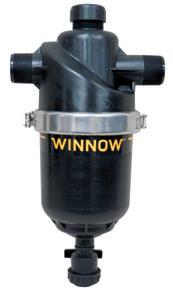
(0.13 to 1.3 microns). Dirty fingerprints can ruin sealing faces. Improper or careless installation, improper
• Patented Inlet Design creates a rapid circular motion of water – causing a hydro-cyclone affect and turbulent cross-flow current over the filter surface.
• Substantially Increased Filter Service Intervals.
• Superior Flow Consistency.
• Flush-Valve for Fast and Efficient Filter Element Maintenance.

operation of the seal piping system or the seal support system, inappropriate mechanical seal selection, inappropriate seal piping plan or seal support system,
excessive pump piping strain, and excessive shaft misalignment can each or in combination have an adverse effect on the life of a mechanical seal.
Ideally, a mechanical seal operates in a cool, clean, and vibration-free environment, in which case, depending on the specific application and operating parameters, a mechanical seal should provide years of trouble-free operation.
Rolling element bearings are the second most common pump element to fail. Rolling element bearings have a statistical life rating, based on failure due to metal fatigue, known as L10 (aka B10), often expressed in hours. At a given shaft rotational speed and load, 10 per cent of ‘identical’ bearings can be expected to fail (or 90 per cent will survive) when the bearing manufacturer’s rated L10 hours have elapsed. Fifty per cent of bearings will survive approximately five times the L10 life rating.
Dimensional standard process pumps have a specified minimum L10 life of 17,500 hours (two years). So the median bearing life for these pumps would theoretically be about 10 years. But pump bearings most often fail long before achieving their ‘natural’ statistical demise due to metal fatigue. Indeed, observed field failures are often related to particulate or water contamination of the lubricant, abrasive
wear, improper lubricant viscosity, mounting damage, misalignment, improper shaft/housing fits, insufficient loading resulting in skidding of rolling elements, shock loading, false brinelling, failure of a bearing separator (cage), or a failure or malfunction of the lubrication system. Debris particle contamination as small as three microns can cause bearing damage. Proper bearing storage, handling, and installation, as well as the initial bearing housing and assembly cleanliness, are factors the pump manufacturer or the repair shop can control. General lubrication cleanliness, control of bearing housing contamination, and monitoring of the lubrication system are factors the pump user can control.
The system, process, and specifying engineers play crucial roles in determining the ultimate life cycle, cost, and equipment reliability by ensuring the pump is properly specified for the properties of the pumped product, the equipment’s operating environment, and the system’s hydraulic characteristics.
Equipment installation also plays a critical role in pump reliability. Proper
setting of the anchors, levelling and grouting of the baseplate, piping up to the pump while minimising strain, elimination of soft foot, and accurate alignment of the drive train contribute to smooth running. Installation and alignment requires care and precision and are best done by or under the supervision of an experienced millwright.
Ideally, a pump is operated at or near its best efficiency point (BEP). The preferred operating range (POR) is typically 70 or 80 to 120 per cent of BEP flow, according to Hydraulic Institute, API, or ISO specifications. The allowable operating range (AOR) is defined by the manufacturer.
Graphically the concept of POR and AOR ranges are shown in Figure 2. The AOR is typically bounded by flows at which the vibration level exceeds a specified value. Pump NPSH-required may be the limiting factor at the high flow extent of the operating range. Turbulence, recirculation, and cavitation come from operating a pump at off-BEP flows and result in energy dissipation forces that act upon the rotor and the pump stationary components. These forces cause displacements and strain, fatigue

and wear, and shorten the pump’s MTBF.
The standards for pump maintenance and repair activities should be no less rigorous than would be expected of newly manufactured equipment. Proper cleanliness, handling, and assembly practices for critical tolerance mechanical seals and bearings can avoid maintenance induced failures and at least give these components an opportunity to achieve long life. Inspection of the disassembled pump also provides an opportunity to discover the root cause of failure.
A thorough treatment of pump reliability encompasses nearly the entire life cycle of the equipment, including selection, design, specifications, manufacture, inspection and testing, shipment and storage, installation, commissioning, operation, and maintenance. When viewed in this context, reliability is a real world activity relevant to all hands involved with the pumping machinery.
For an independent evaluation of pump reliability, contact an experienced consulting engineer who can help with your specific application.

Inpro-Seal


The rapid development of unconventional oil and gas in the US and Canada revolutionised these countries’ energy economies and realised significant economic benefits. Innovative Australian companies are reaping the rewards of this boom, exporting technology and expertise overseas. Now, Australia may be poised for its own ‘unconventional revolution’.
Unconventional oil and gas resources, such as coal seam gas, shale oil and gas, and tight oil and gas, are located in reservoirs with differing geology to traditional oil and gas reservoirs. This means that they cannot be extracted by conventional methods and usually require hydraulic fracturing (or fraccing).
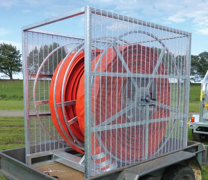
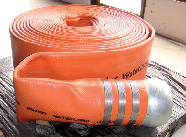
Francois Steverlynck, Managing Director of Crusader Hose, has extensive experience in the industry, with the company’s hoses utilised on various unconventional oil and gas projects in the US and Canada to transport the water required for fraccing.
Crusader Hose is considered a pioneering company in the industry, having recognised and fulfilled the need
for an innovative water transfer solution for fraccing. Crusader’s unique layflat hose is flexible and durable enough to transport water from sources up to 15 km away over uneven terrain, preventing the need for costly infrastructure to be built to store water closer to the well sites. Unlike poly pipes, they are also easy to pack away, store and transport to remote locations and between different well sites.
“Thanks to technological advancements in horizontal drilling and fraccing, many unconventional oil and gas resources that were previously considered too difficult and uneconomical to extract can now be developed,” said Mr Steverlynck.
“Fraccing is already used within Australia to extract coal seam gas, which currently accounts for around 13 per cent of total natural gas production. However, success overseas demonstrates that fraccing can also be safely and effectively used to extract shale and tight gas and oil resources on a commercial scale.”
Over the last decade, the US and Canada have seen an unprecedented boom in unconventional gas and oil production. In 2012, the US became the world’s largest producer of natural gas and the third largest producer of oil. This resulted in increased uptake
of natural gas as an energy source, decreasing emissions despite increased energy production; reduced gas prices, benefiting the domestic market, spurring local industry and increasing the attractiveness of the US for industrial investment; and a significant reduction in North America’s dependence on energy imports, enhancing energy security.
The industry also directly employs over two million people, and around 7,000 US companies are active in onshore gas production.
With geological and industry conditions resembling those of the USA and Canada, Mr Steverlynck believes that Australia has the potential for a similar unconventional oil and gas boom, with similar economic rewards.
Australia is estimated to have resources of around 235Tcf of coal seam gas and 437Tcf of shale gas. Significant tight gas resources are also thought to occur, in addition to around 18 billion barrels of technically recoverable shale or tight oil.
“Australia’s natural gas is an abundant,
lower cost, lower emission energy resource,” Mr Steverlynck says.
“Australia has vast potential shale, tight and coal seam gas resources,” he says. “Not only is there ample gas in these reservoirs to meet the needs of the domestic market, there is enough for increased exports.”
Natural gas is already one of Australia’s largest exports, bringing many billions of dollars into the economy every year. The oil and gas industry also accounts for around a third of Australian business investment, with over $200 billion in project investment committed up to 2017 and another $100 billion possible.
“Developing unconventional gas would be a boon for the Australian industry and the economy,” says Mr Steverlynck. “It would result in direct and indirect job creation, boost the manufacturing sector, foster regional development and contribute billions of dollars in taxation.”
Australia’s energy security and independence could also be significantly enhanced. While the country currently relies on substantial oil imports, Australia has its own substantial
undeveloped oil resources associated with shale and tight reservoirs.
The success of Australian manufactured products on overseas fraccing projects shows that Australia already has access to the technology and expertise to expand its unconventional gas industry.
Crusader’s hoses are an example of an Australian made product that has bucked the downturn in local manufacturing and increased its export market.
Developing unconventional oil and gas will create further opportunities for Australian companies to follow Crusader Hose’s example and expand into a growing area, providing the equipment and expertise for safe and efficient fraccing to both local and international markets.
“The many benefits of hydraulic fracturing and unconventional gas development within Australia are evident,” says Mr Steverlynck. “It’s time for Australia to develop unconventional oil and gas and reap the benefits of becoming a leader in this growing international industry.”

The INPEX-operated Ichthys LNG project is continuing to progress towards first production, with a number of major milestones recently recorded by the project.
Located off the north-west coast of Western Australia, the Ichthys LNG Project is a large scale venture to develop the Ichthys gas and condensate field in the Browse Basin. The project is expected to produce 8.4 million tonnes of LNG and 1.6 million tonnes of LPG per annum, along with more than 100,000 barrels of condensate per day at peak. Construction began in 2012 and first production is expected in 2016.
Under the terms of this new contract, Sulzer will act as the pumps provider for the critical liquids removal system, and will deliver six large API 610 (ISO 13709) Barrel Casing Pump sets. The scope of supply for the pumps includes the six pump skids with electric motors and complex seal systems, which are being manufactured, packaged, and tested in Sulzer’s testing facility in Bruchsal, Germany.
The Sulzer pump model GSF was specifically chosen by INPEX for its ability to meet challenging mechanical and process requirements to stringent project specifications. One of the most critical requirements is high suction pressure design with four operating cases on different liquids with various densities. With only a cartridge retrofit to a fully staged pump and no change to the fixed speed electric motor, the
Sulzer model also allows for minimal downtime and a simpler method of offshore pump retrofit.
The pumps will be installed on the offshore Central Processing Facility (CPF). The CPF is a column-stabilised, offshore semi-submersible production unit supporting hydrocarbon processing systems and utilities, as well as living quarters for about 200 people. At the CPF, the natural gas will undergo initial processing to extract condensate and water and remove impurities in order to make the gas suitable for transmission to Darwin via the 889km gas export pipeline (GEP).
The separated condensate will then be transferred, via the Sulzer pumps, to a floating production, storage, and offloading (FPSO) facility anchored nearby. Installation of the pumps into the module will be supervised by INPEX experts, with future offshore support to be provided by Sulzer Australia.
The Ichthys LNG project continued to progress towards first production during 2014 and the first quarter of 2015. The project reached 50 per cent completion in June 2014, only two-and-a-half years after the final investment decision was made in January 2012; representing a significant milestone for the project.
Drilling began at the gas-condensate field in February 2015. The first
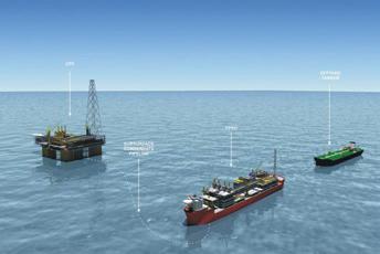
The Central Processing Facility (CPF) where the pumps will be installed.
development well was spudded by the project’s development drilling rig ENSCO5006, which had arrived at the field after undergoing major upgrades in Singapore. A further 20 production wells will be installed in the Brewster reservoir at 4,000 to 4,500 metres beneath the seabed. Directional drilling technology is being utilised and the wells will be grouped around five drill centres, each designed to accommodate four to six wells.
The project also began the deepwater pipelay for its 889km GEP in February 2015. Following the successful completion in November 2014 of the 164km shallow water section by the SEMAC-1, Saipem’s deepwater installation vessel Castorone will lay the remaining 718km offshore section of the 42-inch diameter GEP. The remaining seven kilometres of the GEP will be onshore, incorporating the beach valve and the final section to the onshore LNG facilities site at Bladin Point near Darwin. The deepwater pipelay is scheduled for completion in late 2015.
The city of Bunbury in Western Australia is upgrading the Five Mile Brook pump station. The collaborative approach between client, contractor and pump supplier highlighted the benefits that can be achieved when all parties work closely together.
The City of Bunbury owns and operates a stormwater pump station at the termination point of Five Mile Brook (FMB) in Bunbury. Late last year the City of Bunbury determined the FMB pump station to be inadequately performing and in need of an upgrade.
The FMB open stormwater channel services an extensive area. At the discharge point, the existing arrangement allows stormwater to either drain via gravity or be conveyed by the pump station into the ocean.
The system failed to discharge a sufficient volume of stormwater during severe weather events, particularly during extreme high tide when the gravity flow system was prevented from functioning. Additionally, during heavy rain the pump lacked the capacity to remove the required volume of water from the channel, resulting in potential widespread flooding.
The FMB pump station has been identified as a critical asset, with the upgrade to greatly reduce chances of it failing. This capability will enable the
upgraded pump station to mitigate flood risks for future generations
The scope of works to be completed included:
• Concept design
• Detailed design
• Construction of the pump station, discharge pipe, electrical and control building, and all associated elements
• Commissioning and testing of the pump station.
The tender documentation specified that the upgraded stormwater pump station would include a stormwater discharge capability of 1,000 litres per second; a 400 per cent increase on current capacity.
During normal operation the discharge from the pump station (comprising two identical pumps) will scour the ocean side of the outlet to facilitate a gravity flow function from the FMB pump station to the ocean.
As a primary performance outcome during storm events, and when tides prevent normal operations, each singular pump needed to have the capacity to evacuate stormwater from the FMB pump station.
The FMB open stormwater channel, which terminates at the corner of Ocean Drive and Haywood Street, Bunbury, has an extensive catchment, extending to the areas surrounding Dalyellup and Gelorup within the Shire of Capel.
The design and construction had to consider aspects including public safety, operator safety, cost effectiveness, value for money, operational reliability, operational flexibility and monitoring via SCADA, maintenance requirements, including access, durability and reduced operational input, contingency operating modes, including the provision to hire pump sets or a generator, and security of the facility.

Following the competitive tender process, the City of Bunbury awarded the FMB pump station upgrade contract to Ertech. Both parties took a collaborative approach to the project, establishing a unique working relationship which delivered real benefits to all parties.
Dion Todd, Project Manager at Ertech, outlined some of the particulars of the project.
“The City of Bunbury specified that the pumps selected for the upgrade project be from Xylem, as their existing pump system was a Xylem one.
“Ertech, along with hydraulic engineering consultant Hyder, worked closely with Xylem to develop the right pumps for the system upgrade.
100-year event requirements, and the available power and size of the site.
The team also worked closely with Xylem to specify the right pump for the job.
“Xylem proposed a Flygt pump, and with the right modifications, it proved to be the right pump for the job,” said Mr Todd.
“Given that we were after quite a specific product for the job, the pumps have had quite a long lead time. The pumps have been ordered from Xylem and are being shipped here.
“We developed a close working relationship with Hyder and worked together as a team to decide upon and develop the best pump for the job.”
Because we were working in a brownfield environment, we were after pumps with unique specifications and modifications.
“We developed a close working relationship with Hyder and worked together as a team to decide upon and develop the best pump for the job.”
According to Mr Todd, factors under consideration in the design process included regular performance versus one in
“The pump selection was really the central factor in terms of specification for this project. Once we had the pump locked in, we were able to proceed with many of the other important elements of the project.
“Given the environment we were in, this was a very interesting and challenging project. The Five Mile Brook pumping station upgrade was a unique project, requiring a unique solution, which we believe we are on track to deliver,” concluded Mr Todd.
Works began on the FMB pump station upgrade in February 2015, and is due for completion in the first half of 2015.
Pump Systems Ltd, in association with Vaughan Company Inc, has designed, engineered and supplied a turnkey digester mixing package for Watercare Services’ new 32 metre diameter digester located at the Mangere Wastewater Treatment Plant – New Zealand’s largest.
Vaughan’s custom engineered mixing system, known as ‘Rotamix’, consists of a set of fixed nozzles mounted permanently inside the tank and an externally-mounted Vaughan horizontal end suction chopper pump.
The Rotamix system for the digester (known as Digester 8) uses up to twelve individual nozzles that are strategically positioned and aimed inside the tank to provide a ‘dual-zone’ mixing pattern and to prevent floor settling. Solids are drafted across the tank floor to the peripherals of the tank, where the high velocity Rotamix nozzles direct the movement upwards. In addition, special nozzles positioned up high help to prevent and control scum and foam build-up. Mixing performance is guaranteed and backed by detailed
computational fluid dynamics (CFD) modelling.
Outside the tank, a large, 12-inch discharge Vaughan Chopper Pump continuously recycles the contents of the digester, conditioning the sludge to provide better digestion and to eliminate blockages in piping, nozzles, valves, heat exchangers, and other downstream processes. Rotamix offers excellent process flexibility with the option to run continuously, intermittently, or via variable speed drive, which can account for large energy savings.
Having officially represented Vaughan Chopper Pumps and Vaughan Rotamix in Australia and New Zealand for more than 20 years, Pump Systems Ltd has the experience and knowledge to
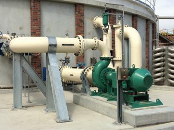
Vaughan model HE12W18 digester mixing pump at the Mangere WWTP.
cater for any application that involves the mixing of solids-laden sludge or wastewater. Australian organisations using Rotamix include Sydney Water, Water Corporation, SA Water, Unitywater and Gosford City Council, to name a few.
For more information on Vaughan Rotamix and Vaughan Chopper Pumps contact authorised Australian distributor Pump Systems Ltd or visit www.chopperpumps.com.au.
For more than half a century, the patented chopping action of the VAUGHAN® Chopper Pump has solved some of the world’s toughest solids pumping problems. With the unique ability to chop all solids at the pump suction, VAUGHAN® Chopper Pumps can handle higher solids concentrations than standard non-clog pumps, providing peace of mind for critical applications.
AUTHORISED DISTRIBUTOR:
PUMP SYSTEMS LTD
Freephone: 1800 121 452
Email: sales@chopperpumps.com.au
WWW.CHOPPERPUMPS.COM.AU
A huge plant treating the effluent of 1.8 million people called for a unique pumping solution.
The Mogden plant, located in the UK, was built in 1936 for the West Middlesex drainage district to replace 28 small sewage treatment works. Over the years it has been expanded, still within the original site boundaries, to now treat the effluent of approximately 1.8 million people.
The plant produces some 96,000 tonnes of sludge cake every year, all of which is recycled to land. Chiswick, Wembley, Edgware, Ruislip, Harrow, Staines and Hampton mark the limits of its catchment, with the River Thames the southern boundary. The plant has a capacity to treat 810 million litres of liquid waste each day. It’s a large site with large maintenance demands, and Thames Water required an appropriate maintenance plan to be established to keep the new pumps at their optimum performance.
The SEEPEX pumps in use at Mogden are used for a variety of applications, from small dosing pumps with liquid polymers to large transfer pumps. Most however are used in the sludge treatment processes from mechanical thickening to pasteurisation, and they handle a variety of different sludges at varying densities and temperature. Each pump is specified particularly for its duty, with consideration of all the varying factors to ensure the pumps are left to operate at their optimum efficiency with minimal downtime.
Mogden is also the home of the monstrous SEEPEX N300-36 sludge surface transfer pumps which transfer 180m³/hr of sludge 16km to another treatment plant. These pumps are fitted with massive 250kW energy efficient electric motors and provide a combination of flow and pressure unmatched worldwide.
With 16 weeks to implement – a recordbreaking time frame – a project team of 30 spanning all departments within the company designed, manufactured and delivered these giant pumps. At 11m long and almost seven tonnes in weight, they represent a new milestone in the development of progressive cavity pumps, enabling the company to penetrate markets that are traditionally associated with large piston pump technology.
The core of the progressive cavity pump, the rotor, was manufactured from one single piece of tool steel which initially consisted of a billet weighing 1.7 tonnes and finally ended up at 0.7 tonnes and almost 6m long and within accuracies of 0.2mm.
The stator concept utilised considered aspects of health and safety relating to manual handling, during both assembly and future servicing whilst ensuring optimum pump performance.
SEEPEX were asked to offer service capabilities to assist Thames Water with planned and reactive maintenance to some of the more specialised SEEPEX progressive cavity pumps and associated grinders. The service had to be comprehensive, cost effective and reliable in order to meet the high demands of running the third largest effluent treatment plant in Europe.

SEEPEX started by delivering this service by means of a monthly service visit to check and maintain just 28 of the 55 pumps and to take care of any maintenance interventions identified as a result of the checks. This reduced the sludge pump downtime so successfully that SEEPEX were soon asked to take on more pumps.
Since their installation in 2003 these massive pumps have been pumping sludge 16km day in and day out without the use of any spare parts.
SEEPEX now has responsibility for all of the SEEPEX pumps at the site and also all of the pumps at Mogden’s sister site Iver South in Slough. SEEPEX had proved it was much more than a pump supplier, and that the service consultation package offered delivers less repairs, less downtime, less usage of parts and more importantly reduced costs of ownership.
SEEPEX UK is contracted to carry out planned and preventative maintenance to a total of 68 progressive cavity pumps and grinders at two sites ranging from polymer dosing pumps to massive sludge transfer pumps. Checks are thorough. Dry run, over pressure, wear, drive condition and efficiency are all checked on a monthly basis. Wear rates are predicted as a result of these checks and preventative interventions are carried out before downtime occurs and when required they are carried out within one working day, on site. As a result neither site has experienced any unplanned downtime due to sludge pump failure since the agreements were put in place.
For further information on how these technologies and principles can benefit local sewage installations, please contact SEEPEX Australia on 02 4355 4500 or info.au@seepex.com
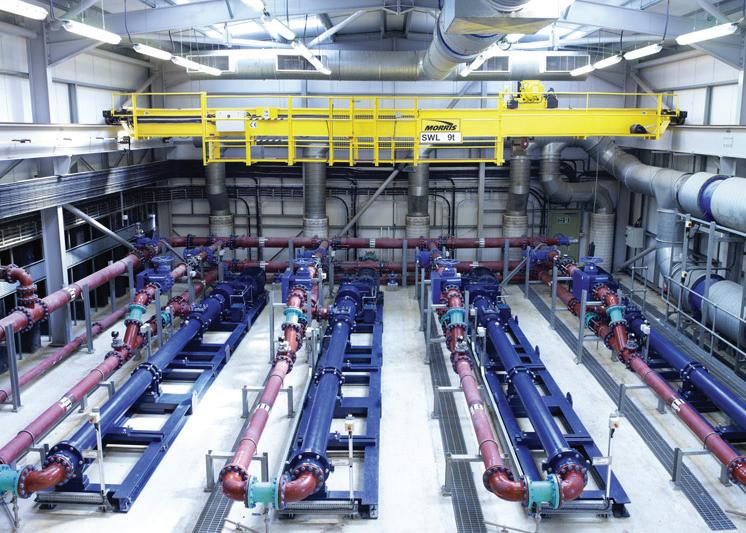
The giant pumps manufactured by SEEPEX.
Key Facts
• Flow rate and pressures unmatched worldwide
• Record-breaking time from concept to delivery
• 1.7 tonnes to 0.7 tonnes with accuracies with 0.2mm
• Service consultation package
Significant Cost Savings
• Efficiently transfer thickened sludge 180m3/hr 16 km
• Less usage of spare parts
• Less repairs
• Less downtime
• Labour cost saving
Installed Pump Type
• Range N
As the world moves to a more sustainable future, designers and wastewater asset owners are expected to, and are doing, the same. They are looking predominantly at energy savings, but are they concentrating too much on the momentary efficiency achieved with clean water when the pumps are tested when new? And are they also considering the consumption of other finite materials when considering pumping station designs? Hydro Innovations helps to answer these questions.
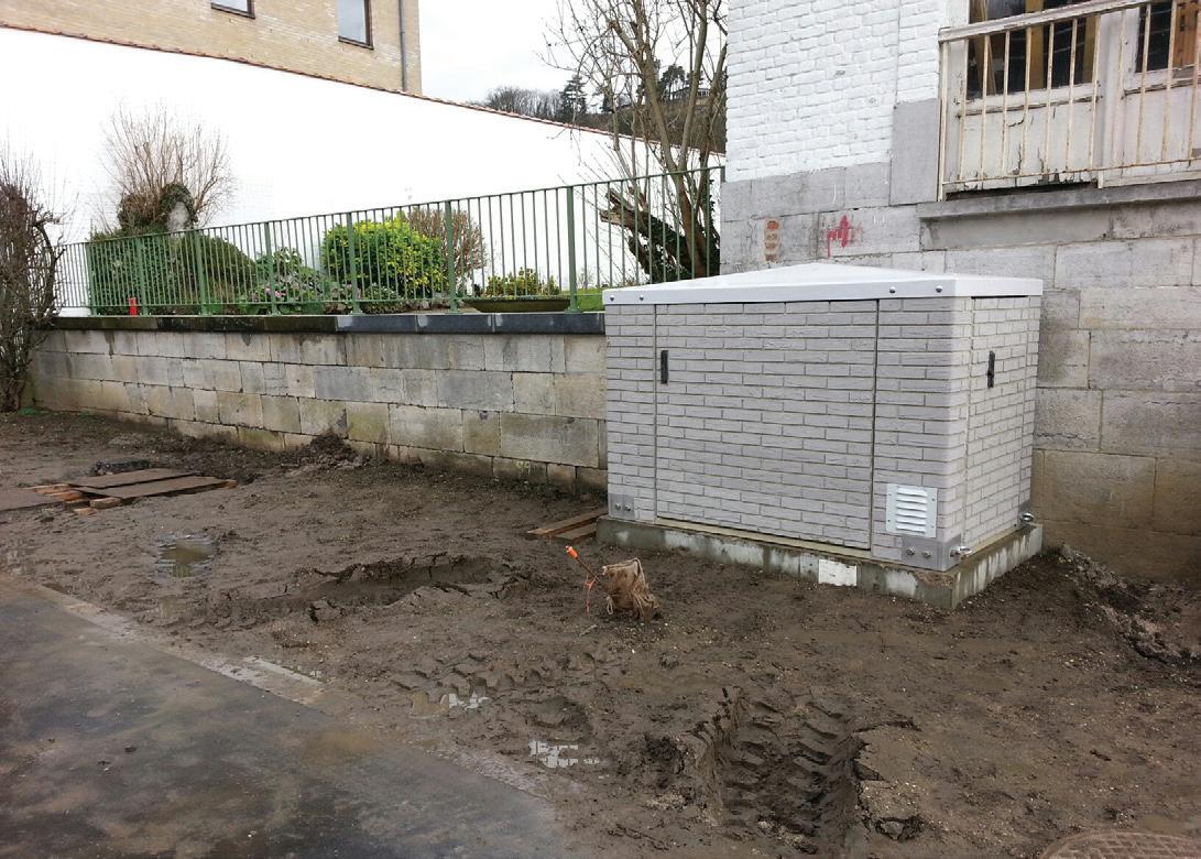
The general industry standard is to design new wastewater pump stations with two submersible pumps sitting at the bottom of a wet well which has been designed to be large enough to house the two pumps, and have enough capacity to allow the minimum amount of starts per hour. Wells will generally be 2-3m in diameter and house guide rails, discharge bends, ladders and liquid level control devices. Pumps may be selected against criteria which may include pump efficiency.
During the life of the pump station, efficiencies will decrease because of general wear, but also because of partial blockages (which are hard to detect) and any losses through leaking discharge connections. Pumps will run for longer hours, consuming up to 40 per cent more energy than expected. The wearing can be catered for by adjusting or changing wear rings, but this needs several operators and lifting apparatus, so may not be done as regularly as needed. This gets tolerances back to ‘new’, but does not address the partial blockage issue or the lost energy through leaks in discharge connections. At some stage the guide rails will need replacing, as will the discharge elbow and possibly lifting chains. This scenario may not be considered the most sustainable solution.
Some designers are thinking outside the box, and are looking for pumps to deliver sustained efficiency for the life of the pump, and are looking for more sustainable total solutions.
Using Gorman-Rupp self priming sewage pumps, wet wells can be much smaller (because only the suction lines and liquid level devices need to be inside the well), guide rails are not needed (so don’t need to be replaced), and neither are discharge elbows and lifting chains. This constitutes a reduction in the raw materials needed to construct the wet well and maintain the items in it over the life of the asset, not to mention the use of cranes and vehicles to provide this maintenance won’t be necessary (decreasing the carbon footprint).
Gorman-Rupp sewage pumps also have
a self cleaning wear plate system to greatly reduce the incidence of partial blockages, and externally adjustable clearances that requires only minutes from one operator to keep pumps at peak efficiency (not hours by several operators as is the case with submersible pumps). Again, decreasing the carbon footprint.
Surface mounted pumps may not be the solution for all wastewater pumping stations, but because of their sustainable efficiency, easy access and
safer working environment for operators and smaller wet well needs, Hydro Innovations believes that they should be considered.
For the complete white paper on wastewater pump operator safety, go to www.pump-stations.com.au or call Hydro Innovations on 02 9898 1800 or email sales@hydroinnovations.com.au.


The recent signing of an agreement between Brisbane City Council and two leading infrastructure partners is an exciting first step towards Brisbane developing the first CBD district cooling system in Australia.
The innovative scheme, which aims to replace existing individual chillers and cooling towers in CBD buildings with a centralised plant, supplying chilled water via a network of underground pipes, is tipped to deliver a range of energy savings and environmental benefits.
Brisbane City Council (BCC), through its subsidiary CitySmart, is partnering with Cofely Australia and Thiess Services to develop the energy efficiency infrastructure project, which will see the construction of a central system which pumps cold water to buildings for cooling purposes.
The technology is already in use in many projects around the world, but Brisbane will be the first Australian city to implement such a scheme on such a large scale in a CBD.
The project is expected to deliver significant cost savings for businesses by providing greater system efficiency, eliminating capital expenditure on replacing old chilling machines and facilitating a shift to off-peak energy consumption, with peak energy demands expected to drop by up to 20MW per annum.
What is a district cooling system?
A district cooling system (DCS) is a centralised water chilling system that replaces air conditioning chillers and cooling towers within individual buildings, supplying them instead with chilled water through underground pipes. When combined with thermal energy storage (TES), the system can chill water during off-peak periods and then supply it to buildings during the day.

The system would consist of one or more centralised plant rooms, and a series of pipes under the city to connect the buildings to the system.
The DCS will result in significant energy savings for individual buildings (and overall), as well as significant cost savings. The cost savings are achieved through greater system efficiency, avoidance of capital investment as well as a shift to off-peak energy consumption.
The project delivers multiple benefits and would be a flagship Australian economic development and energy efficiency infrastructure project, as it would be the first DCS to be implemented on this scale in a CBD. The learnings from this project could be shared across other Australian cities and major regional centres.

The project leverages proven technology that exists in over 1,000 projects globally and operates at a university campus level in Australia.
A sustainable cooling vision CitySmart has been working with council and industry partners since 2011 in undertaking the feasibility assessment of DCS infrastructure in Brisbane’s CBD.
This has resulted in the deal between BCC and Cofely Australia and Thiess Services, a two-year development agreement which allows for the feasibility finalisation and design phases of DCS for the Brisbane CBD.
This two-year contract enables Cofely Australia and Thiess Services to:
• Secure investment for the future project
• Secure customers for the future project
• Design and plan delivery of a project likely to be delivered in a number of stages following the completion of this contract period.
The two-year contract period is timely as there are a number of key developments planned for the CBD during this period, such as Queens Wharf, allowing Cofely Australia and Thiess Services to liaise with stakeholders to assess and negotiate feasibility of incorporation of these developments as part of the
project. The two-year time frame allows for proper consideration of the future needs of the development zone.
The project will be a flagship economic development and energy efficiency project for Brisbane. Initial feasibility investigations have estimated that the capital investment in the project, at the completion of all stages, could be in excess of $230 million, with economic benefits of over $530 million, and the creation of over 500 jobs.
While the project is revolutionary in Australia, centralised energy systems have been widely used for both heating and cooling in a host of European and Asian cities, including Paris, London, and Singapore.
The consortium has identified around 200 CBD buildings suitable for the district cooling system, with around 25 per cent of them potentially able to connect within the next five years.
Since the signing of the deal late in 2014, Cofely Australia and Thiess Services have been lobbying CBD building owners to sign up to the scheme.
The team from Cofely Australia will be designing the pump system that will drive the distribution of chilled water across the Brisbane CBD.
According to Cofely Australia Technical Manager Dr Nick Regan, “Our pump
District cooling system at a glance
selection process will be based on whole of life cost effectiveness, including capital efficiency, maintenance requirements, and replacement expenditure.”
This process is currently ongoing and will be informed by the pump selection process followed by Cofely on other major DCS projects around the world, such as the Climespace Paris project.
Cofely Australia Managing Director Vaughan Furniss said “Having completed our own independent survey of Brisbane’s CBD energy requirements, we are confident of delivering a world class district cooling project with Thiess, which will deliver energy, capital
and cost savings, giving Brisbane a competitive edge over other capital cities in terms of affordability and resilience.”
Richard Kelleway, Executive General Manager, Thiess Services added “The contract will pave the way for a lower energy requirement for Brisbane city for decades to come.
“The selection of the Cofely Australia and Thiess Services consortium to develop a district cooling proposal to the next stage is a significant step towards managing the long-term energy and peak demand requirements for the CBD.”
A district cooling system replaces the current chilling machines in buildings with one central system (a chilled water plant) in the CBD that pumps cold water to buildings for cooling purposes, and returns the hot water for ‘re-chilling’, through an underground pipe network. A system may include thermal storage that allows the plant to operate at night at lower cost and higher efficiencies and removes load from peak electricity demand during the day. A number of buildings sign up as customers who pay for a cooling service based on a commercial proposition of lower cooling costs, avoided capital expenditure on replacing old chilling machines and no more legionella risk in the building.

FEATURES:
S Measures energy wastage
S No flowmeter required
S Easily installed
S Excellent long term stability
S 5 year equipment warranty
BENEFITS:
S Reduce operating costs
S Reduce maintenance costs
S Improve process efficiencies
S Valuable Asset Management tool
S Reduce carbon emissions
S Replace conventional flow meters

Bearing lubrication is an essential component of proper motor maintenance. Here, Heinz P. Bloch explains the differences between re-greasable and lifetime bearings, and introduces recently advanced PFPE greases and the financial benefits they may have for business owners.
Bearing lubrication guidelines have existed ever since bearings were first designed and manufactured. The vehicle owners of antiquity had leather cups secured to the bearing housings of their supply wagons and war chariots. These cups were filled with animal tallow and topped by a smooth stone. This stone applied the pressure needed to force the tallow or grease into the wheel bearing clearance gap. Similar single-point lubricant application devices exist today, except that metal or plastic have taken the place of leather cups. Also, instead of tallow, users now have access to a multitude of different grease formulations. And yes, the pressure-applying stone has been out of favour for a while. It was replaced by a spring or by pressurisation via an inert gas.
While the above could rightfully be called ancient history, even modern grease application practices follow historical precedents and are influenced by long-established perceptions. One of these precedents is depicted in Figure 1, representing a reasonable and widely used standard re-lubrication guideline published decades ago (Reference 1 and 2). This guideline is still valid within the context of its intended application; it relates to premium mineral oil-based greases at ‘average’ temperatures but severe loads.
Common re-lubrication intervals (Figure 1) are often recommended as a function of shaft speed ‘n’ (r/ min) and bearing bore ‘d’ (mm). As illustrated here at 1,000r/ min, 80mm bore diameter ball bearings should be re-greased after
approximately 3,000 operating hours. In high temperature applications, bearing manufacturers generally recommend suitable adjustment factors (Reference 1 and 2). Because adjustment factors are percentage multipliers (0.7, 0.8, or other numbers below 1.0), it can be shown that bearings at higher than ‘typical’ operating temperatures will require more frequent grease replenishment. Not to be overlooked, effective motor re-greasing is greatly facilitated by knowing the grease path through the bearing. For that reason, best-of-class user-purchasers specify bearing configuration just as they, of course, specify motor voltage, power, speed, service factor, and wire insulation grade.
Existing re-greasing charts apply only to hydrocarbon oil-based greases
• At 1,000 rpm and shaft diameter of approximately 90mm, a tapered brg. ( “c”-scale) would be re-lubed after ~1,000 hrs.
• At 1,800 rpm and the same shaft diameter the tapered roller bearing ( “c”-scale) re-lube recommendation moves to ~400 hrs.
Anticipated life of bearings which cannot be re-greased
But what if timely and precautionary grease replenishment was not possible because a bearing had been provided with seals? Sealed bearings (Figure 2, Item 5) are often called lifetime lubricated bearings. For sealed bearings with mineral oil-based greases, Figure 1 can still be consulted to make rough estimates of probable operating life to failure. Without grease replenishing, it was usually assumed that a particular bearing would live until double the recommended time-between-replenishments would be reached.
The following example will illustrate this approximation:
This time, we opt to use Figure 1 and assume 60mm (shaft) diameter ball bearings operating at 3,600r/min. A vertical line would be plotted from 3,600r/min (on the x-axis) to intersect the 60mm curve. From there, a horizontal line would be drawn to the ‘a’ column (on the y-scale). It would show grease replenishment recommended after 2,000 operating hours, or about four times a year. However, because sealed bearings cannot be re-lubricated, cautious industrial users often invoke a somewhat conservative rule of thumb. This rule of thumb would be to multiply the recommended interval by a factor of two. In this instance, one would replace such bearings after one year of operation – a rather costly practice. Therefore, a more sophisticated user would probably purchase re-greasable 60mm bearings for the aforementioned 3,600r/min motor running conditions and periodically re-lubricate these ‘open’ or ‘shielded’ motor bearings with premium-grade (mineral oil-based) grease twice yearly.
PFPE greases: a mature life extension option
However, another option – perfluoropolyether (PFPE)based greases – has recently been advanced. PFPE-based lubricants are non-flammable and offer extremely high tolerance to heat and chemicals. They will not oxidise or gum up like other greases, nor can they be displaced by low-pressure steam and water. In addition to these desirable features, PFPE greases contain no volatile organic compounds (VOCs) or chlorinated compounds.
In particular, these greases should be explored in view of highly favourable long-term experience at a major pulp and paper mill located in western Canada. Prior to using sealed bearings filled with PFPE grease of the right viscosity, the company faced a challenge regarding its electric motors. With over 3,000 motors on site, it was becoming increasingly more complex to properly and economically service each motor with customary lube planning and work procedures.
The motor bearings and housings at this mill included cross-flow and same-side grease reservoirs, and singleshielded as well as double-shielded bearings. Some of the single-shielded bearings were oriented with the shield away from the grease reservoir while others – more appropriately – had the single shield adjacent to the grease reservoir. Grease relief ports were needed for the various re-greasable motor bearing housings. But these ports were not always ideally situated, nor were drain plugs in these ports consistently removed before and re-installed after replacing or replenishing grease.


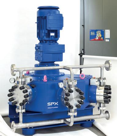
With its laterally and angular offset pump heads, the effective and space saving technology of the NOVAPLEX Vector sets new standards. This is why the NOVAPLEX Vector is ideally suited for mounting in tight areas. This triplex process pump with its innovative design is suitable for use in EOR (Enhanced Oil Recovery) and Oil & Gas as well as many more applications in the chemical and petrochemical industries.
To learn more, visit us at www.spx.com.au
Contact us at Tel: (03) 95899222 or
Email: ft.aus.cs@spx.com

1. Inner ring
2. Outer ring
3. Rolling element: ball, cylindrical roller, needle roller spherical roller
4. Cage
5. Capping device seal – made of elastomer contacting (shown in figure) or non-contacting
6. Outer ring outside diameter
7. Inner ring bore
8. Inner ring shoulder diameter
9. Outer ring shoulder diameter
10. Snap ring groove
11. Snap ring
12. Outer ring side face
13. Seal anchorage groove
Figure 2. Bearing nomenclature with terminology item 5 (seal versus shield) of interest.
Without well-understood or uniformly specified bearing and housing configurations, re-lubrication routines were likely to include occasional overgreasing or under-greasing. Grease contamination is an additional risk factor and the Canadian paper mill, at one time, decided that leaving the bearings alone was the most prudent course of action.
Therefore, the pulp and paper mill had chosen to run their electric motors without a re-lubrication process. They knew that electric motors in their harsh paper mill environment usually lasted no longer than four to years, with over 60 per cent of the breakdowns attributed to bearing lubrication failure. When motors would unexpectedly fail, the mill would often have to repair them in-house. This, usually, required overtime pay and costly downtime.
These important factors and
considerations led the mill to move towards using only life-time greaselubricated sealed bearings whenever an electric motor had to be serviced. But lifetime lubrication with mineral oil-based greases would still require relatively frequent pre-planned bearing change-outs; the anticipated bearing life without re-lubrication would stress the mill’s maintenance budget. It was at that point that the PFPE alternative became very attractive and Figure 3 provided analytical back-up for the anticipated superiority of PFPE greases. It should be noted that PFPE is the liquid base oil in the generic PFPE mineral oil-free family of products. PFPE is the actual lubricant whereas PTFE is the thickener in this family of mineral oil-free electric motor bearing greases (Reference 3).
The Weibull plot in Figure 3 shows the failure probability of an optimally
formulated PFPE-based motor bearing grease to be 20 times less than that of the traditional premium shear-stable polyurea grease. The PFPE grease provider’s plot was rather compelling and prompted the paper mill to request an accelerated bearing life test. The test results closely matched expectations and convinced the mill’s maintenance manager to move ahead on a proposal to use only PFPE pre-filled ‘lifetime lubricated’ bearings. From then on, these would be installed whenever motors had to be serviced in any way or required replacement for any reason.
Seven years later, the mill had successfully converted bearings to PFPE-based greases in over 100 motors. They also stocked over 150 additional PFPE-based grease-filled sealed bearings and planned to swap these into motors as the old bearings failed.


From the time PFPE lubricants were applied, the mill has not had a single unplanned bearing failure, nor have they had to replace any electric motors which use this grease. On top of the reliability successes, the use of PFPE grease has helped provide a simple solution with less manpower. For this mill, it clearly proved the most cost-effective option and seven years of tracking showed the mill to have nearly doubled the life of their electric motors. The labour component of periodic re-lubrication no longer exists and each avoided motor replacement event saves the mill at least $4,000. For this Canadian paper mill, any maintenance program requiring periodic re-greasing would have meant more manpower and added overhead costs.
The paper mill was probably correct in disregarding the (academically justified) minor incremental frictional losses. All bearings consume energy and the –conceivably – higher loss attributable to PFPE greases can be explained. If they could even be measured, higher losses would simply be due to PFPE grease having a somewhat higher density than that typically found in ‘traditional’ electric motor greases. That said, and as demonstrated by this case history, PTFE-based greases can be used to move productivity and failure avoidance at pulp and paper mills to new levels. On top of being strongly endorsed by end users, PFPE greases are recommended by many major bearing manufacturers for long-life lubrication of electric motors. At an average replacement cost of $4,000 per motor, many users have joined the Canadian paper mill in seeing favourable results add up rather quickly.
It can be demonstrated that PFPE greases are an optimum choice for long-life bearing lubrication in severe applications. Using these greases in sealed lifetime lubricated bearings will virtually eliminate bearing failures attributable to lube application errors. Greased-for-life PFPE-filled bearings will also eliminate the cost-of-labour component of periodically re-lubricating bearings.
References
1. SKF Bearing Maintenance Handbook, (1996) Publication 4100/I E.
2. SKF General Catalogue, (2003) Publication 5000 E.
3. Bench Test Data, DuPont ™ Krytox® Lubricants, Data Sheet K-23698-4.
Welbull Probability Plot
Included lives: L10 | Conf interval: 90% - 2 sided
Local Manufacture and Local Support from a company that designs and manufactures in Australia

COMPREHENSIVE PUMP TESTING UP TO 1.2MW
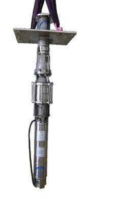


• Engineered submersible motors 4” to 24”
• Fabricated stainless steel submersible pumps and motors
• Vertical turbine pumps 6” to 90”

ENGINEERED SUBMERSIBLE PUMPS AND MOTORS
• De watering pumps
• Submersible Sewage pumps
HORIZONTAL SPLIT CASE PUMPS - UL LISTED
Some things are getting smaller. Consumer goods continue to shrink year on year, model upon model, as manufacturers strive to extract more out of less. The demand for increased capabilities has continued and this has resulted in design spaces becoming more cramped.
Regarding fluid dynamics, increased pump and motor dimensions, combined with smaller facility sizes, often result in situations where assembly space for pump and motor is greatly restricted. Critically, situations that involve manoeuvring large masses of equipment for maintenance purposes result in expensive downtime.
KTR has considered these issues when developing the ROTEX®S-H (split hub) flexible shaft coupling.
With this design, the hubs are mechanically separated by ‘cracking’ on purpose. An uneven surface with a positive fit is the result, ensuring an exact position of the two halves during assembly. The contoured, uneven cracked surfaces ensure an ideal centering of the hub halves.


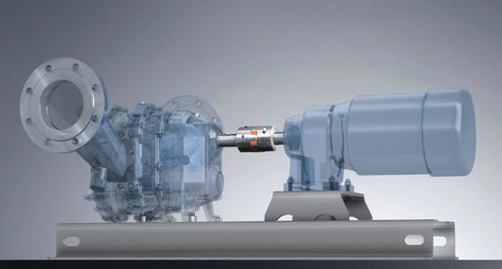
This guarantees that the hub or the connection of the two hub halves, respectively, is not weakened by the separation by cracking. The ‘cracked’ hub is screwed in place in block assembly and makes sure that during operation there is no negative impact on the strength of the coupling.
The fact that the hubs can be assembled and disassembled radially makes it highly suitable for mounting in narrow mounting spaces. The ROTEX®S-H has the advantage that its hubs can be installed radially without the need to move or disassemble system components – pump and motor stay put!
Other benefits include:
• Easy assembly/disassembly by means of four-off screws
• Centering of both halves of the hubs through the fracture surface
• Specifically suitable for tight mounting spaces.
• Finish bore according to ISO tolerance H7, feather key according to DIN 6885 sheet 1 (JS9)
• The product has all the benefits of a conventional ROTEX® with KTR’s T-Pur® elements.
Deanquip Powertrans is the exclusive agents for KTR in Australia, and has the ROTEX®S-H available ex stock.
Deanquip engineers can assist with any design or retrofit requirements.


The world depends on energy services companies to power our lives. And energy companies depend on John Crane to keep their operations running efficiently. We develop innovations needed for mission-critical operations and challenging environments. Ensuring greater reliability. More uptime. And rapid response when customers need us.
We are globally recognized for designing and engineering high-quality, durable, customized solutions. These solutions — ranging from seals, filtration systems and bearings to couplings and artificial lift equipment — are backed by the largest global service network in the industry. We combine technical expertise and innovation, geographic reach and superior quality standards, and customer service and responsibility to provide the reliability, efficiency and constant uptime on which our customers depend.
Contact a John Crane expert today to learn how these products - and more - can help keep operations safe, reliable and environmentally compliant.
When pumps at Energy Australia’s Mt Piper Power Station needed to be repaired, the energy utility knew exactly who to call on.
Energy Australia’s Mt Piper Power Station is located 175km west of Sydney in Portland NSW. It operates two coal-fired units producing a total of 1,400MW at peak production. The power station features Ebara pumps, for which Hydro Australia are the authorised service repair agents in Australia. After initial discussions and dismantling of the pump had taken place elsewhere, the pump’s damaged and dismantled inner cartridge was sent to Hydro Australia’s Morwell workshop in the Latrobe Valley, Victoria. After a detailed inspection, report and work scope was prepared, the decision was made for Hydro Australia to carry out the refurbishment.
The pump design is typical of many Australian coal-fired power stations. Multistage, barrel casing, with a two-piece inner volute operating at over 5,600RPM. Although Hydro Australia has been a major pump refurbishment contractor to Energy Australia’s Yallourn Power Station in Victoria for many many years, this was the first such contract at Mt Piper.
The scope of work required included replacement of all the usual consumable components expected with a rebuild, plus new impellers, balance drum, balance sleeve, wear rings and the shaft – all in all, a major repair. The other significant component requiring attention was the inner volute. Initially it was expected that the inner volute would require replacing, however Hydro Australia had completed similar work on several other rebuilds previously, and felt that it could be repaired instead.
The inner volute would require a full weld repair at every internal and external locating diameter. Once the welding was completed by Harvest Engineering in Melbourne, stress relieving was the next step, followed by machining and lapping of the split face joint and full line boring to renew all the internal locating diameters. This took place at Hydro Australia’s workshop, with round-the-clock shifts required at various stages.
Hydro Australia’s repair methods are rarely as the pump was originally built. With the advances in material technology, composite materials, designs, procedures and standards, all Hydro Australia refurbished pumps will return to the client a technically better pump and this case was no different. Time to refurbish means time to improve and upgrade for reasons of efficiency, reliability, long-term performance and increased mean time between repairs (MTBR).
An additional problem with the boiler feed water pumps is corrosion problems to the mechanical seal water jackets.
Unlike newer design feed pumps, the water jackets on the Ebara pumps are not removable items. The jackets are welded in place and form an integral part of the barrel casing on one end and the discharge head on the other.
To repair this problem, Hydro Australia was able to put their new on-site, in-situ machining system to work for the first time in NSW.
A secondary contract was issued for the on-site work. In short, this contract included removal and installation of the Hydro Australia refurbished cartridge, overhauling the feed pump booster pump, repairing the water jackets and laser aligning the entire train including the booster pump, gearbox, Voith fluid coupling and feed pump.
Hydro Australia’s suggestion was to machine and remove the existing water jackets, manufacture new stainless steel inserts and face plates and weld in place. With this task never completed previously, and with a lot of unknowns, including new obstacles encountered along the way, timing was a concern. With continual communication and working together successfully the entire job continued trouble free.
All the barrel repair work was completed on-site, in situ with the removable discharge head sent to the Hydro Australia workshop in Victoria on a fast turnaround, with a similar work scope to that of the barrel.
Other checks were carried out on-site including a full barrel concentricity and parallelism inspection using the site machining equipment, and weld repairs to O-ring grooves in the discharge head.
The work was completed several days ahead of schedule, on budget and to a safety level meeting Energy Australia’s high standards, completely incident free.
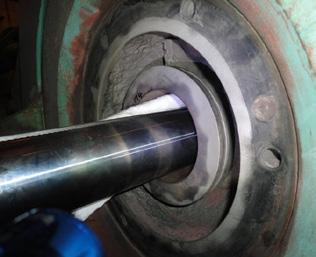
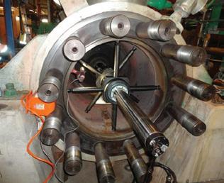
Hydro’s on-site machining system in place.
Many of the pumps installed at power stations and in other industry applications throughout Australia are in the range of 25 to 35 years old, be it a condensate pump, cooling water pump, booster pump, boiler feed pump or a simple axially split case water pump. With recent advances in materials technology, composite materials, machining tolerances, component design, assembly practices, and with enhanced attention to detail, the MTBR of Hydro Australia-refurbished pump equipment is continuing to increase substantially.




Society is facing considerable challenges in the light of global warming and world population growth, and reducing energy consumption is a priority around the world. What many people fail to realise is that simple changes to common industrial practices can make a big impact on our global energy use.
According to the World Health Organisation there is a direct correlation between world population growth and water consumption, the number of motor vehicles on the road, increasing carbon dioxide emissions and the demand for electricity. In this context the concept of efficiency takes on major significance with a view to accommodating a good deal of the extra energy demand in the future. In the field of refrigeration, air conditioning and building systems, the use of energy-saving drive units for fans and blowers can make a great contribution to such efforts.
The influence of energy-saving fans on energy consumption and carbon dioxide emissions can best be illustrated by a concrete example: use is frequently made of asynchronous motors as drive units in refrigeration, air conditioning and building systems. These AC motors are of simple, compact design as they take their supply directly from the AC or three-phase AC network. They do not require any mechanical commutators or electronic components for supplying the rotor. They are both robust and reliable. However, their one major drawback is their comparatively poor efficiency. Particularly in the part load range they are clearly inferior to electronically commutated (EC) motors, which operate at around 70 per cent efficiency. This has a significant effect on power consumption in virtually all applications.
The size 68 AC motor provides a clear example to illustrate the point. It was developed by ebm-papst in 1963 and is the basis for many other motor sizes. It is still used in a wide range of applications. Over the past
five years, and assuming an average power consumption of 150W and a duty cycle of 75 per cent, the annual energy consumption of the 25 million AC motors employed as fan drive units in various applications was not far short of 25TWh (25 billion kWh). That represents the combined output of Australia’s two largest power stations, which produce about 28TWh per year. To put it another way: two large coalfired power stations are necessary to supply the AC motors used in a fiveyear period in various fan applications in refrigeration, air conditioning and building systems.
AC to EC – exchange made easy The figures show that it is essential to reduce the demand for energy in the future – and it can be done. Thanks to the development of a new series of EC motors, ebm-papst is now in a position to replace conventional AC motors with highly efficient EC technology with the same mechanical design. It is basically the same process as for old 100W light bulbs, which can be replaced by efficient LEDs, fitting in the same holders. The development of mechanically compatible EC motors and their extremely compact design did nevertheless represent a technical challenge.
The EC motor concept is based on synchronous motors with permanent magnet commutation. The magnetic rotor operates in synchronism with an electronically generated rotating field. This makes it possible to achieve any required operating speed irrespective of the mains frequency concerned.
Accommodation of the electronics required for EC motors in a confined space (Figure 1) demands a lot of
experience and expertise. Mechanical compatibility is also necessary in addition to the miniaturisation and optimisation of the electronics. This includes employing the same type of mounting flange as for AC motors (Figure 2), as well as modification of the motor design as a whole.
The results are impressive. The new compact ebm-papst EC motors are based on the successful external rotor principle in which the rotor rotates about the internal stator. A number of practical advantages are gained from the thermoplastic encapsulation of the laminated core of the stator. The high-grade plastic material provides excellent electrical insulation and it is possible to integrate the ball bearing mount. This permits variation of the wall thickness and spacing, making it easy to compensate for laminated core tolerances. Finally, the entire wound assembly is encapsulated in thermosetting plastic (Figure 3). The one-piece rotor moving around the stator is of optimum aerodynamic design. Air inlets in the rotor ensure ideal dissipation of the stator heat. In combination with the encapsulated stator the motors have a high level of protection (IP54). Sealing of the electronics also plays an important role. In contrast to previously used concepts involving a flange and various O-rings, the electronics housing was provided with an elastic sealing component to ensure long-lasting protection of the electronics. The entire motor is robust and shock proof whilst offering outstanding reliability and a long service life.
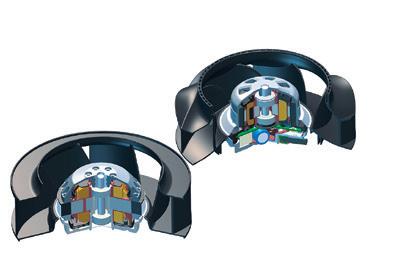
Figure
AC motors (on the left), thus permitting simple mechanical exchange.

When designing and manufacturing the new EC motors, great emphasis was also placed on sustainability and the preservation of resources. This is demonstrated by a variety of details. For instance, the one-piece rotor with press-fitted shaft reduces the number of manufacturing steps and fewer parts are required thanks to the use of multi-function components. The heat dissipation concept and a relatively short core also help to reduce the amount of material used.
The energy efficiency of EC motors is also associated with other properties which have a positive influence in everyday operation. These include speed control by way of the integrated electronics for example. The speed can thus always be matched to the given requirements. Additionally, EC motors run much quieter than speed-controlled asynchronous motors due to the noise generated by the triac or frequency converter control employed by the latter. Other advantages include high power density, compact size and a monitoring function which permits interrogation of operating data and statuses at all times.
A variety of applications already implemented provide ample evidence of the environmental, financial and practical benefits to be gained by swapping from AC to EC motors in refrigeration, air conditioning and building systems.


ebm-papst Australia and New Zealand distributes world leading fans and motors of its German parent company to the Australasian market. We will provide you with optimised fan solutions and technical answers. Whether you need peak energy efficiency, the quietest system or optimum value, we will work hand in hand with you and your team to make sure it is the best solution.
www.ebmpapst.com.au

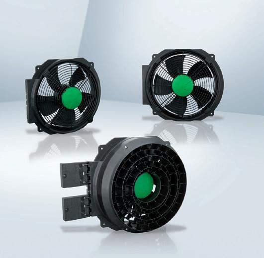

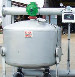
This applies to the evaporator unit fans used around the world in refrigeration systems, for instance to transmit heat in cold storage areas (Figure 4). As such systems operate with a high duty cycle, power consumption can be reduced considerably by using EC motors. And the AxiCool range of EC fans designed specially for this sort of application has even more advantages to offer: they are able to withstand the harsh cold storage conditions, produce little heat in the refrigeration system thanks to the high level of motor efficiency and can be regulated to suit requirements.
One less coal-fired power station
There is no end to the list of possible examples, encompassing EC blowers in range hoods or clothes dryers, duct fans, fans in refrigerated display cases and fans in ventilated façade systems. Common to all is an average reduction of energy usage by about 40 per cent when switching from AC to EC motors. Going back to the previous figures involving 25 million AC motor applications, here is another interesting thought: if all 25 million AC motors were to be replaced by EC versions and assuming a potential average energy saving of 40 per cent, the annual saving would amount to nearly 10TWh. The efficiency of EC fans in refrigeration, air conditioning and building systems would therefore permit an entire coal-fired power station to be shut down – an indisputable contribution to reducing the world’s energy consumption.
The ebm-papst group is the world’s leading manufacturer of fans and motors and is a pioneer and pacesetter for ultra-efficient EC technology. ebm-papst fans and motors are represented in many industries, including ventilation, airconditioning and refrigeration technology, household appliances, heating engineering, in IT/telecommunications, in medical technology and in applications in automotive and commercial vehicles engineering. Find out more about ebm-papst ANZ at www.ebmpapst.com.au.
More than 90 years young
• Pump repairs onsite mechanical repairs and upgrades.
• Repair bands, gibaults, filters/screens, media tanks, saddles, foot valves.
• Filtration systems, manifolds and more.
• Standard sizes in stock or made to order.
• Aluminium, stainless and steel fabrication.
• Plasma cutting, pipe work manufacture and install.

Founded in 1899, Kelly & Lewis has a proud history as a pump design and manufacturing company that extends over a century. Continuing the coverage of the history of the Australian pump industry, which we began in the November 2014 edition, here we explore the company’s long history. We map their growth through both world wars and their evolution into Thompsons Kelly & Lewis, through to the company’s eventual decline as tariffs forced an end to Australia’s manufacturing industry.
Kelly & Lewis was founded in 1899 by Edward Powell Lewis and George William Kelly after the pair met through Atlas Iron Works. Their business relationship soon developed into a solid friendship, and the two had often discussed going into business together. But a murky economic climate still recovering from its slump, and the need for start-up capital, left Lewis hesitant to leave his position of Works Manager at Thompson’s Foundry.
Despite his hesitations, Lewis managed to source financial backers, and in September 1899, they established their firm under its original name of Geo W. Kelly & Lewis.
The firm began with £6,000 in capital, and progressed well up until the First World War. They initially worked out of Kelly’s original blacksmithing shop in Melbourne, and staff included a clerk, a typist, and several draughtsmen. Steady business allowed the firm to grow, and they soon employed 50 men across their three departments: blacksmithing, boilermaking, and the machine shop. Eventually, a large order placed by Victorian Railways for locomotive cylinders demanded greater capacity, and the firm moved to larger premises which they continued to expand over the years.
In its first 15 years, Geo W. Kelly & Lewis experienced continued growth, taking on larger and larger contracts. In 1913, the firm had been converted into a proprietary company and had capital of £50,000. When World War
I began, the company moved into munitions production, with a contract for 18 pounder shells. The company also collaborated with inventor Mr A. de Bavay to build the required equipment. They also produced the first aircraft engines made in Australia. Though wartime production deadlines placed considerable pressure on Kelly & Lewis, they continued to plan ahead and commenced two developmental projects to be continued when peace was restored, which included expanding into other states.
When peace arrived in 1918, the firm had established its position and reputation. George Kelly passed away in 1919, and control of the business passed to Edward Lewis and his son E Llewellyn Lewis, who was a Director of the company. By 1921, the Lewis family had repurchased all of the company’s shares. Expansion required the firm to move, and by 1927 the new plant in Springvale was fully operational. The economic recession of the 1930s curtailed production, and the firm experienced a difficult economic period. Edward Lewis passed away in 1930, with management passing to his sons Llewellyn and Kelvin Lewis. The firm began producing high speed dieselpowered engines, and established a subsidiary engine business. In 1939 the proprietary company was converted into a public company, and in 1940 the company’s name was changed to Kelly & Lewis Ltd.
Throughout World War II, Kelly & Lewis greatly expanded its range of
equipment. The company designed and manufactured steam generating sets, high-pressure portable pumping plants, portable electric generating sets, tank transport trailers, fuel pumps, and steel telegraph poles and radio masts. The company also supplied thousands of centrifugal pumps for water supply to industry and camps.
Post-war, Australia proceeded with many large-scale development works. Kelly & Lewis accordingly established and acquired multiple manufacturing subsidiaries. Having diversified their group structure, the company focused on product research and development, setting up laboratories at the Springvale site. By 1950, a range of centrifugal pumps had been developed in the hydraulic laboratory, which had a range of equipment including generators, dynamometers, switchboards, flow measuring systems, and calibration tanks.
Lithuanian engineer Andy Gasuinas was appointed Chief Hydraulic Designer in November 1950, and the Model 50 pumps range was produced to replace the pre-war design by 1955. The company also produced Model 55 solids pumps, Model 60 and Mixed Flow Volume (MFV) pumps, and commenced developing the modern design for split casing pumps. Mr Gasuinas introduced conformal transformation vane design technology, as well as hydrofoil variablepitch design for axial flow pumps. Though economic downturn affected sales, Kelly & Lewis was awarded a large contract by the Melbourne
Metropolitan Board of Works (MMBW) for the supply of large sewage pumps. The company secured manufacturing licences from the US, including one from Pacific Process Pumps to APA 610 specifications for the oil industry. Following company reorganisation, Kelly & Lewis emerged in 1960 with a slimmed-down group structure, and by 1961, the company had been purchased by UK company Mather + Platt.
In 1968, Kelly & Lewis established a new Board of Directors to assess the company’s position and make strategic decisions for the future. In 1969, Kelly & Lewis attempted a takeover of its biggest competitor, Thompson’s of Castlemaine. Thompson’s turned hostile and sold a large parcel of shares, blocking the takeover. In May 1969, the company was awarded a large contract by the MMBW, which included four 48-inch fixed-speed pumps and four 48-inch variable-speed pumps. They also produced 42 GIW slurry pumps and cooling water pumps for Swiss Aluminium’s Nabalco Plants in the north of Australia. By mid-1971, the new range of centrifugal pumps designated ‘Model 70’ had been designed and were in production. In 1975, the company won a contract for eight 16-inch GIW hard metal slurry pumps for Bougainville Copper.
In 1969-1972, the Tariff Board conducted an inquiry into the pump industry, and cut its tariff protection from 55 per cent to 27.5 per cent, with ongoing annual reductions of 2.5 per cent. Then, in the early 1970s, the Federal Government cut protective tariffs across the board to 25 per cent. Unable to compete with cheaper foreign imports, pump manufacturing in Australia slowly declined. The effect that these policies had is reflected in Kelly & Lewis’ employment figures: in 1974, the company employed 700 people, but by 1986 this number had shrunk to 335.
In 1973, Kelly & Lewis acquired the licensed rights to manufacture and sell Worthington products in Australia. This included the purchase of the Worthington Manufacturing plant in
Penrith, NSW. Managing Director Harry Smith then acquired Fluid Dynamics, a Melbourne-based company that was developing a range of submersible sewage pumps. In 1975-76, the company was awarded a contract by MMBW for four large pumps and ancillary equipment to be installed at the Yering Gorge Pumping Station. By the end of 1976, Kelly & Lewis Group had developed a very wide pump product range, and was the leading pump manufacturer in Australia
In 1976, Wormald International attempted a takeover of Kelly & Lewis’ parent company, Mather + Platt. By 1 January 1977, Wormald International became the owners of Mather + Platt. Wormald International also had the chance to buy Kelly & Lewis’ main competitor, Thompson’s Byron Jackson of Castlemaine, but opted not to. In 1979, the Wormald Australian Machinery Group (WAMG) was formed, with headquarters in Melbourne. Record profits were recorded in 1978-79, and further contracts had been obtained, including six vertical mixed flow diffuser (MFD) pumps for the Hope Valley Water Treatment Plant.
In 1981, with a recession forecast, Kelly & Lewis won a large contract for the Loy Yang Power Station, which included eight 1,200mm/1,400mm horizontal split-case, double-suction, circulating water pumps. In 1983 discussions began on the design of end-suction centrifugal pumps to ISO standards, which would replace the Model 70 as an all-purpose unit. The KL-ISO range consisted of 32 pumps in sizes from 32mm to 200mm discharge diameters. With the Australian dollar strengthened, exporting was expensive, and additional union troubles resulted in a plant being established in Japan. KL-ISO pumps were in full production by late 1985. The continuing recession and pressure from imports resulted in the company recording a lower profit for 1983-84. The company also won a contract from the Brisbane City Council for two highcapacity 72-inch MFD vertical pumps with capacities of 110,000 gallons per minute at 66 feet total dynamic head. Despite this, profits had again fallen,
This is an edited extract of Robert Moore’s book, Kelly & Lewis: A fine old engineering company – its rise and demise, which is available from the PIA. Visit pumps.asn.au/publications.
and in 1984-85 Kelly & Lewis only managed to break even.
Though parent company Wormald International was experiencing financial woes, Kelly & Lewis had prepared a strategic plan and budget to return to profit in 1985-86. Attempting to recoup capital, Wormald International sold off many of its subsidiaries, and decided to merge Kelly & Lewis with Thompson’s Byron Jackson. The new entity of Thompsons Kelly & Lewis (TKL) began operating on 1 January 1987, and Kelly & Lewis ceased to exist.
Also in 1987, BTR Nylex acquired Thompsons Kelly & Lewis, a purchase driven by BTR Nylex Managing Director Alan Jackson – who had begun his working life at Kelly & Lewis and ultimately served as a Managing Director of the company. Following the acquisition TKL continued producing high quality pumps, and continued to be awarded contracts throughout Australia. The Institution of Engineers Australia awarded TKL with an Engineering Excellence Award for the manufacture and installation of eight giant sewage pumps at the MMBW’s Brooklyn Pumping Station. Between 1987 and 2004, TKL recorded profits of between seven per cent and ten per cent.
After a number of corporate mergers, TKL eventually came to be owned by US company Flowserve in March 2004, and TKl’s operating name changed to Flowserve Pump Division Australia.

Bernard Hasell worked in the pump industry for almost 50 years, beginning in 1944. Now a happy retiree, his pumps career began with tooling manufacturing, and extended into many different areas of the industry. In this interview, we talk to Bernie about his long career and the changes he has witnessed, particularly the decline in Australian pumps manufacturing.
When did you first get into the pumps industry?
My employment commenced on 4 February 1944 when I served three months in the production department on stock records prior to being indentured as an apprentice. My training commenced in the tool room on tooling manufacturing. After approximately two years a vacancy came up in tool design and this lasted about 18 months. Then I was transferred to the main design drawing office, where I was involved with general engineering works involving underground winders, power stations, feed heating equipment, engines, carbon ring compressors, etc. This continued until 1960 when the company became a licensee to Pacific Pumps of California. Part of the condition was that I spent three months in the US, where I became fully involved in pumps and applications up until my retirement in 1993. All told, I was with Kelly & Lewis for 49 years and eight months.
What do you like about the pump industry?
My involvement in the pump industry was complex, as it involved selection, quoting, selling, following up with clients, expediting, and commissioning. My involvement also included negotiating with our manufacturing as this was not the only product in manufacture. The beauty of my position is that it involved all aspects of the product and I met with all kinds of conditions, both with our own people and with our clients.
What other companies have you worked for during your time in pumps?
As previously stated, I had the unusual employment experience of working for only one company in my entire career.
How has the industry changed during your time in it?
The industry has changed vastly. While we once had many big manufacturing companies, the country now does not have the ability to do major turnkey and other large pumping contracts. These are now all situated overseas.

Bernard
“The greatest challenge is getting back to local manufacture so the industry is less dependent on foreign imports.”
What is your most memorable moment from your career?
My most memorable moment was in 1973 when I went to the UK on a major pump application for PRA in Adelaide and met the people I had corresponded with at Foster Wheeler.
Did you have a mentor at any time in the industry?
My mentors during my working years were many in many different aspects. During my apprenticeship, my father Alex was the tool room foreman, and served as my mentor. Then, in the drawing office, they were Eric Engbrigtsen and Ben Woodbridge, who in my opinion
had no peers. At the pumping company, Project Manager Bill Holyoake steered me through my learning years in sales and contracts.
Who were some of the other personalities in the industry that you have worked with?
Other personalities were the clients, purchasing and expediting staff, and engineering people in all aspects.
What are the most significant developments you have witnessed in the industry?
The most significant development is the demise of pump manufacturing in Australia. The lack of engineering apprentices speaks to the lack of opportunity.
Are you still involved in the industry today?
After nearly 50 years, I have no regrets with my life. I’ve been retired for 22 years and am enjoying every minute of it.
What are the greatest challenges facing the pump industry? What does the future hold for pumps?
The greatest challenge is getting back to local manufacture so the industry is less dependent on foreign imports. Initially, my experience began with process pumps in refineries. In the 1960s era, all were brought in from overseas and local manufacture commenced. We had local companies vying for a fairly small market for the number of pumps required. These companies included Industrial
Engineering, Ingersoll Rand, Kelly & Lewis, Thompson’s of Castlemaine, United Process Pumps, I.R., Pacific, and Byron Jackson. All have since been merged and local manufacture of pumps products has almost disappeared. We are a small market worldwide and to revitalise this is now almost impossible. Luckily, I have my memories of great opportunity and now enjoy my life playing golf, going on holidays, and spending time with my family.
Readers and PIA members will no doubt be familiar with the Australian Pump Technical Handbook, the book first published in the 1980s which has been the seminal text for the Australian pump industry for more than 30 years. In this new series, we’ll be featuring edited extracts from the book to introduce the next wave of the industry to this classic book; and remind others of the ongoing value it offers.
Anyone familiar with the pump industry will be well aware of the sheer breadth of different pump designs available and the vast array of different pumping applications. But how are all these different pumps classified? In this article, based on chapter two of the Australian Pump Technical Handbook, we look at the main differences between various pump types and the how these relate to function and classification.
Although a wide range of pumps are available for numerous applications, most fit into one of two main groups. These are:
• Rotodynamic pumps
• Positive displacement pumps.
Rotodynamic pumps
Rotodynamic pumps are those where energy is transferred to the pumped fluid via a rotating element, such as an impeller, propeller or rotor.
Types of rotodynamic pumps
There are many different types of rotodynamic pumps suited to varying applications.
Centrifugal pumps
Centrifugal pumps are a type of rotodynamic pump in which a shaft-mounted impeller rotates unidirectionally within the pump casing.
Centrifugal pumps can be subdivided depending on the type of impeller used:
• Radial flow impellers
The liquid enters the impeller axially and discharges radially, changing the direction of the flow 90°. These impellers can be single suction (where the fluid enters
the impeller from one side) or double suction (where fluid enters from both sides).
• Mixed flow impellers
The liquid enters the impeller axially and discharges in both radial and axial directions. Can be single or double suction.
• Axial flow impellers
The liquid both enters and discharges from the impeller axially (i.e. the flow does not change direction). Single suction only.
Regardless of the impeller type, centrifugal pumps can be either single stage, where the total head is the result of one impeller, or multistage, with a series of impellers aligned in one casing.
Depending on requirements, centrifugal pumps can be either self or non self-priming and can have open, semi-open or closed impeller types.
Centrifugal pumps can also be identified by their basic mechanical configuration or characteristics. For example:
• Overhung impeller type
The impeller is mounted on the end of the shaft that is cantilevered from its bearing supports.
• Impeller between bearings type
The impeller is mounted on a shaft between bearings situated at both ends.
• Turbine type
Usually refers to vertical multistage deep well type pumps with diffuser casings attached to one another.
Other types defined by unique characteristics or functions include sump pumps, sewage pumps, slurry pumps and more.
Radial Flow
Mixed Flow
Centrifugal
Rotodynamic
Peripheral
Axial Flow
Single Stage Multistage
Jet (Ejector Boosted)
Gas Lift
Special
Electromagnetic
Single Suction Double Suction
Peripheral pumps (also known as side channel or regenerative turbine pumps) are rotodynamic pumps where energy is transferred to the fluid within the cells of a vane wheel impeller with a large number of radial blades. Peripheral pumps can be single or multistage and can come in various configurations.
Other types of rotodynamic pumps
Additional types of rotodynamic pumps exist and are defined by their unique functions. These include:
• Jet pumps
A high velocity jet of fluid is used to create a low pressure area in a mixing chamber, causing the suction fluid to lower into this chamber.
• Gas lift
A gas pressure source is used to lift the liquid by mixing it with gas under pressure (usually air).
• Magnetic drive pumps
A sealless type pump that uses a magnetic coupling device so that the external rotating part of the coupling is separated from the internal rotor.
• Electro-magnetic pumps
A glandless pump where a magnetic field acts upon the medium (e.g. liquid metal).
Self-Priming Non Self-Priming
Single Stage Multistage
Single Suction Single Stage Multistage
Open Impeller
Semi-Open Impeller
impeller
impeller
Positive displacement pumps are pumps in which force is exerted upon movable boundaries of enclosed fluid containing volumes, resulting in a direct increase in pressure.
There are many different types of positive displacement pumps.
Reciprocating pumps
Reciprocating pumps are positive displacement pumps that incorporate a piston/plunger, diaphragm inlet and outlet valves, and a means by which the piston/plunger and diaphragm can be actuated (for instance, an electric motor, diesel engine or steam turbine). Types of reciprocating pumps include piston pumps, plunger pumps and diaphragm pumps.
Reciprocating pumps can be either single acting, where the liquid is discharged only during the forward motion of the piston, or double acting, where the liquid is discharged during both the forward and backward motions. Plunger and diaphragm pumps are single acting, while piston pumps can be double acting.
Single Acting
Piston Plunger Diaphragm
Reciprocating
Controlled Volume
Positive Displacement
Single Rotor
Rotary
Multiple Rotor
Reciprocating pumps can be further divided as:
• Simplex pumps
Containing one single or double acting piston/plunger.
• Duplex pumps
Containing two single or double acting pistons/plungers.
• Triplex pumps
Containing three single or double acting pistons/plungers.
• Multiplex pumps
Containing more than three single or double acting pistons/plungers.
Controlled volume pumps
Controlled volume pumps (otherwise known as proportioning or metering pumps) are specialised reciprocating positive displacement pumps which provide precision control of very low rates with a flow rate accuracy typically within + or – 1%.
In construction, they are generally piston or plunger pumps, mechanical diaphragm pumps or hydraulically actuated diaphragm pumps.
Air operated double diaphragm pumps
These reciprocating positive displacement pumps are sealless, self priming and have the ability to run dry for long periods and will not over pressure.
Rotary pumps
Rotary pumps are positive displacement pumps that generally consist of gears, vanes, screws or similar elements enclosed within a casing. They have no separate inlet or outlet valves and fluid flows through the pump in a uniform stream.
These pumps can be divided into either single rotor or multiple
Double Acting
Mechanical Diaphragm
Piston/Plunger
Hydraulically Actualed Diaphragm
Vane
Piston
Flexible Member
Screw Gear
Lobe
Circumferential Piston
Screw
rotor types. They can then be further classified by the pumping element.
Single rotor types include:
• Vane pumps (vane in rotor or vane in stator).
• Piston pumps (axial reciprocating or radial reciprocating).
• Flexible member pumps – where the vane, tube or liner is flexible enough to accomplish sealing and transfer fluid within the casing.
• Screw (progressive cavity) pumps.
Multiple rotor types include:
• Gear pumps (external or internal gear) – where the meshing of two or more gears provide the pumping action.
• Lobe pumps – where the rotors consist of one or more lobes which interact to transport fluid from inlet to outlet.
• Circumferential piston pumps – where liquid is transported in the spaces between the piston surface to the outlet.
• Multiple screw pumps.
Further information and detailed diagrams and schematics can be found in the Australian Pump Technical Handbook, available from the PIA website (pumps.asn.au/ publications). In the next edition of Pump Industry we will take a detailed look at the characteristics of centrifugal pumps.

What is the function of a pump internal relief valve on positive displacement pumps?
Ask most pump people “What is the function of an internal relief valve?” and the most frequent answer is “The valve is there to protect the pump should overpressure occur”.
While not entirely incorrect, consider the consequences of an internal relief valve in full bypass. Against a closed valve or other downstream blockage, the pressure will quickly spike to the full bypass pressure setting of the internal relief valve and the same volume of liquid is recirculated internally.
As the pressurised liquid passes the poppet to the low pressure side of the valve, its energy is converted into heat. The vast majority of input power supplied to the pump from the driver is also transformed into heat. This heat then raises the temperature of a relatively small volume of liquid circulating within the pump and the pump itself.
For some applications, this added heat may be inconsequential, but for others it may damage the pump or product inside. These include, but would not be limited to, mag drive pumps, shear
sensitive liquids, liquefied gases or liquids with a tendency to thermoset, coke, or liquids that may be otherwise damaged by high temperature.
The purpose of the internal relief valve is to provide system protection from overpressure conditions resulting from blockage of the pump. A pump with an internal relief valve may still fail due to higher valve settings, long term valve bypass, and the reasons and examples above.
When supplying a pump with an internal relief valve, consider the following questions:
Should a secondary means of overpressure protection be included to protect the pump as well as the system?
Is an internal relief valve the best option or would a return-to-tank or inline relief valve be a better solution?
2015
feature
manufacturing
Focus
SPECIAL FEATURE - Pump people November 2015
Main feature
efficiency
Focus
generation
Related Products
and drives
Pump Products
Pump Products
protection
Instrumentation, control & monitoring Pressure and temperature gauges
instrumentation Flow meters
monitoring sensors
SPECIAL FEATURE - Industry capabilities guide
February 2016
Main feature State of the industry
Industry Focus
and slurry pumping
& heavy industry
Pump Products
& maintenance
Related Products
and piping systems
casting
pumps
SPECIAL FEATURE - State of the Industry survey
May 2016
Main feature
Industry Focus
& Gas: LNG
pumps
Related Products: Seals
& seals
systems
rubber, chemicals Pump Products




For over 70 years Franklin submersible pumps and motors have proven to be ideal for the most demanding applications. They offer unmatched reliability, service and availability for all your pumping needs.
