Dewatering mines for safer communities



Pump Industry Australia Incorporated
PO Box 55, Stuarts Point NSW 2441 Australia
Ph/Fax: (02) 6569 0160 pumpsaustralia@bigpond.com
Ron Astall – President United Pumps Australia & Astech Consulting Services
John Inkster – Vice President Brown Brothers Engineers
Kevin Wilson – Treasurer/Secretary Executive Officer
Keith Sanders – Councillor Executive Officer – Marketing & Statistics Life Member
Alan Rowan – Councillor Executive Officer Publications & Training Life Member
Ken Kugler Executive Officer – Standards Life Member
Ashley White – Councillor Davey Pumps
Frankie Camilleri – Councillor John Crane
David Brooks – Councillor Flowserve FSD
Dave Alexander – Councillor KSB
Jamie Dixon – Councillor White International
“I
t’s really just common sense!” I was in Auckland, at an IPENZ evening meeting in front of a large group of engineers. With my PIA President’s hat on, I had just completed my somewhat controversial presentation; Are Your Pumps Running Too Slowly?
One of the organisers had kindly got up to say a few words of thanks and smiled broadly and said; “It’s really just common sense!” He was being generous and complimentary and I was grateful to have had the opportunity to attend a lively meeting. Whilst my topic was at first pass perhaps counterintuitive (higher speed pump selections being potentially more efficient and reliable), he contended that once you worked through the logic, it was indeed just common sense. I believe that this is true of most things technical. If you take the time to look at the issues and the logic, it often becomes quite simple. Unfortunately, the thought processes required to simplify things are typically not easy, do take time and we are all often guilty of intellectual laziness.
At PIA we are becoming heavily involved in pump-related energy efficiency initiatives through the Federal Emissions Reduction Fund (ERF) and
the NSW Office of Environment and Heritage. The challenge is to distill our collective experience into practical guidelines and initiatives that reflect a common sense approach that is understandable and will allow the realisation of the massive energy savings that PIA believe are possible in pumping systems. At its core, this approach must emphasise the critical role of system design as the number one priority. A badly designed system with the most efficient pumping equipment installed will still be a badly designed system.
The USA’s Hydraulic Institute and the British BPMA are at the forefront of pushing a system approach when assessing the energy efficiency of pumping systems. I have been reading the HI publications on optimising pumping systems, variable frequency drives and the BPMA’s life cycle costs. It is indeed all common sense, but if we are to reap the rewards we must embrace the intellectual rigor, understand the basic techniques, and take action if we are to reap the rewards.
Ron Astall President, Pump Industry Australia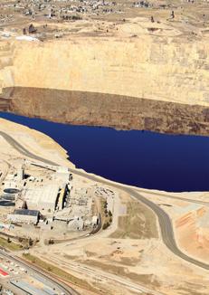
3,404
ABN: 36 426 734 954
PO Box 1763
Preston South VIC 3072
P: (03) 9988 4950
F: (03) 8456 6720
monkeymedia.com.au
info@monkeymedia.com.au pumpindustry.com.au magazine@pumpindustry.com.au
Publisher and Editor: Chris Bland
Managing Editor: Laura Harvey
Marketing Director: Amanda Kennedy
Marketing Consultant: Aaron White
Associate Editor: Jessica Dickers
Contributing Editor: Michelle Goldsmith
Senior Designer: Alejandro Molano
Designer: Jacqueline Buckmaster
Contributing Designer: Sandy Noke
ISSN: 2201-0270
This magazine is published
All communication should be directed to the
The publisher welcomes contributions to the

’m observing with cautious optimism the signs of hope we’re starting to see in the pump industry. While new construction in the resources industry remains quiet, this has become the new normal and many have instead shifted their focus to maintenance, meanwhile many other areas of pumps, including water, irrigation, and building services continue to perform strongly.
My view is shared by a number of the leaders we interviewed in this issue for the second installment in our “Pump People” feature. While all of our interviewees have their own unique take on things, the thing they all have in common, like myself, is a belief that the industry will recover and prosper in the long run. The first tentative steps that are being taken now are positive news for the industry as a whole.
That said, there’s no denying we have a long road ahead of us. Fortunately, other industry sectors are providing bright spots of opportunity for those involved in the pump industry. Wastewater, in particular, continues to provide us with opportunities to manufacture, supply, service and maintain the pumps charged with the critical (albeit not particularly glamorous) role of transporting and treating the our wastewater.
As is often the case, this issue of Pump Industry will have additional
event distribution, in this instance at the Queensland Mining & Engineering Exhibition, being held in Mackay in July, and at the Victorian Water Industry Operations Conference and Exhibition, held in Bendigo at the end of August.
It’s timely that this issue will be distributed at these events. In the mining sector, the signs of hope will buoy those exhibiting at and attending the event. In the water sector, the ongoing challenge of managing the networks required to safely, efficiently and sustainably provide water and wastewater services will keep attendees busy, constantly on the lookout for innovative new products and services to improve operations in the sector.
I hope you enjoy this issue of Pump Industry, and I’d like to take the chance to remind you all that the next issue of the magazine will feature our second annual Pump Industry Capability Guide. We launched the first issue of the guide in November last year, and the publication was a resounding success. I know many companies were disappointed to miss out on the opportunity to have a listing in the first edition, so I encourage you all to start planning your entries in the guide now.
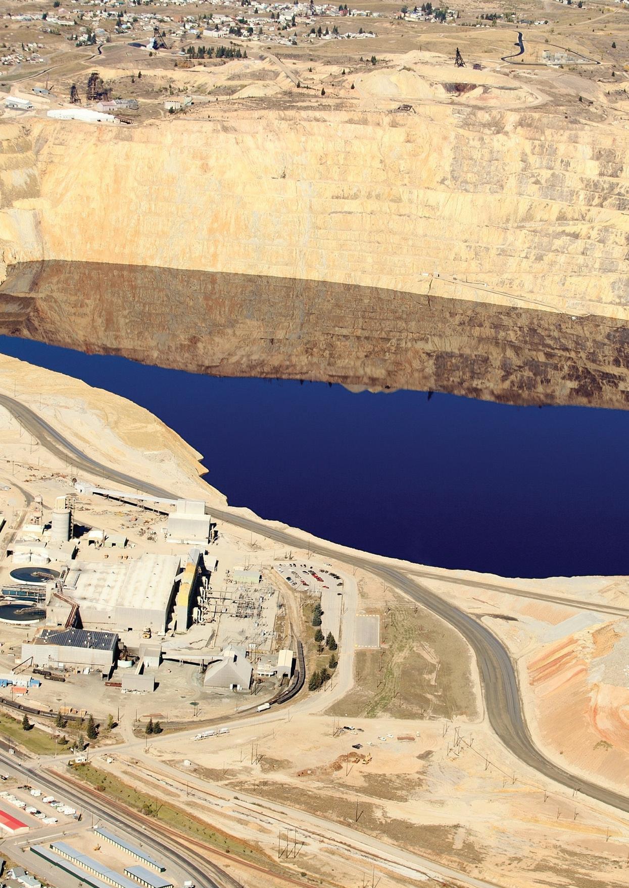
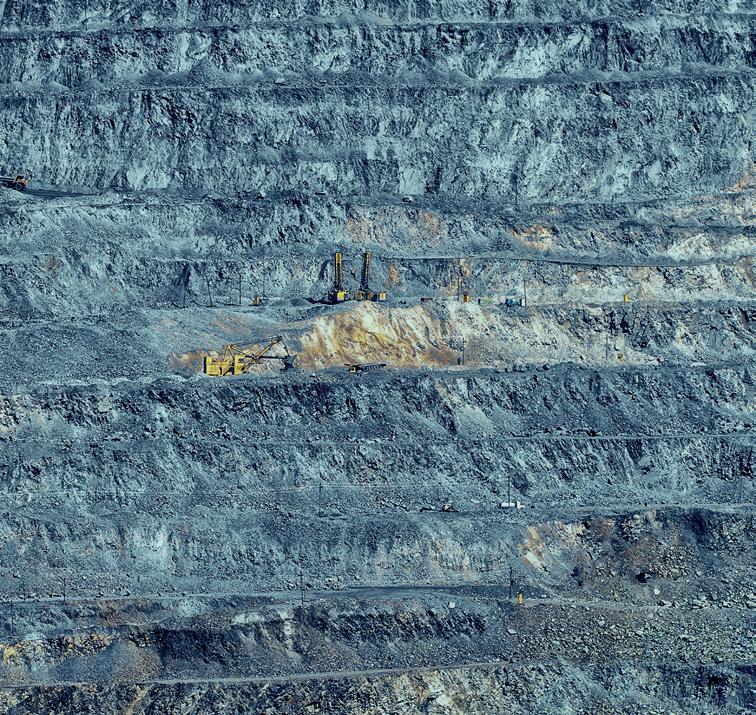
Chris Bland Publisher and Editor Cover image highlights our features on mine dewatering and wastewater. Published by Monkey Media Enterprises
The HDP series consists of a range of heavy duty parallel helical reducers that feature advanced designs and robust build quality to ensure trouble free and quiet operation in all water treatment applications.
The nodular cast iron housing ensures robustness even in the harshest of applications, whilst the strict assembly tolerances and fully ground gears provide an extremely quiet and vibration free operation.
With over 100 years of gearbox assembly knowledge, local stock holdings, dedicated HD application engineers, 24 hour service and an extensive list of aerator application references, Bonfiglioli can provide you with a complete Heavy Duty aerator drive solution.
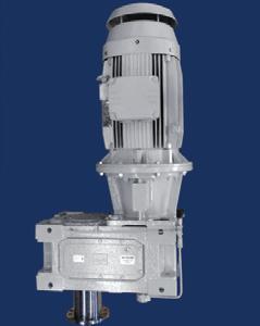
Series: HDP parallel helical
Size: 14 sizes available
Torque Ratings: 4,650Nm - 194,050Nm
Reduction Ratio: 7.1 - 534.5
Input Options: High Speed shaft, IEC close coupled.
Output Shaft Options: solid shaft + rigid flange, hollow keyed, shrink disc.
Options: Mechanical and motor driven forced Lubrication systems, cooling systems, oil level sensors, heavy duty output bearings, drywell, taconite seals, rigid output mounting flange.

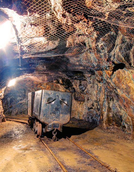
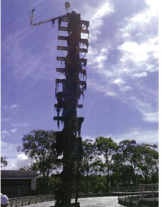
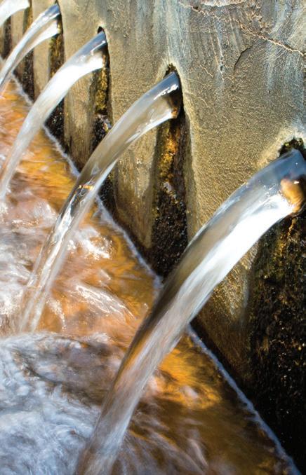
Pump Industry magazine has taken a peek behind the scenes, gathering together some of the influencers within the industry to gain an insight into their careers in pumps. Here, we take a look beyond the technology and the issues and meet the personalities that make the pump industry Down Under tick.
PIA MEMBER NEWS


boosting Queensland’s gas
caught up with Bill Coulter to reflect on his years as a pioneer of the Australian pump industry.
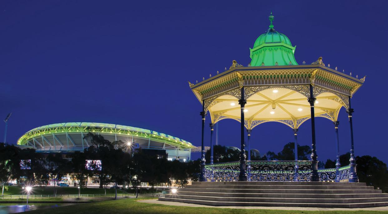
The PIA will host a Technical Presentation Meeting in Adelaide in August, with member company Grundfos hosting the event.
The meeting will be held on August 2 and will kick off at 4.30pm. Refreshments will be served following the meeting.
There will be four speakers during the meeting, each presenting on a topic that will be of value and interest to people working in, supplying to or using
the pump industry. PIA President Ron Astall will be co-ordinating this event and will provide more information on the speakers and their topics as we get closer to the event.
The PIA invites our members, suppliers, customers and anybody else who has an interest in the pump industry to come along and benefit from the opportunity to learn something of the latest technologies and other issues impacting on our industry in Australia.
This will also be a unique opportunity for those based in Adelaide to network with others with similar interests in this important Industry.
Date: Tuesday 2 August 2016
Venue: Grundfos Pumps 515 South Road Regency Park SA 5010
Time: 4.30pm
Townsville City Council has reached an agreement with SunWater to pump water from the Burdekin Dam in Queensland, ensuring supply during current drought conditions.
The council now has access to 16,000ML of high priority water from SunWater and an agreement for the rights to 20,000ML of medium priority water, enough to supplement reserves in Ross River Dam through to mid-2017.
Securing the rights to the high and medium priority reserves in the Burdekin will provide the council with 223 days of water available to pump.
The Burdekin pipeline was built specifically for times of drought, and this year will be the first time the city has had to pump for a substantial period for more than 20 years.
The agreement was reached after SunWater CEO Nicole Hollows and SunWater chair Leith Boully travelled from Brisbane to discuss the issue at a special council meeting.
Townsville Mayor Jenny Hill said the water allocations from the Burdekin Dam would safeguard Townsville’s supply against another failed wet season.
“Our priority is to secure Townsville’s water supply well into next year with a contingency that will safeguard the city against another failed wet season,” Ms Hill said.
“It was pleasing to have SunWater at our meeting to confirm that water from the Burdekin was guaranteed, and they were willing to work with council on an acceptable agreement for the city.
“While the council will plan and
budget for every eventuality, if we receive decent rain in the Ross River Dam catchment and the pumps are turned off, we will only pay for what we use.
“As a result of this agreement, the purchase price and pumping costs for the entire water allocations would be $7.7 million, but significantly less if we get a wet season.
“That’s well below the amount of $12.4 million for a year’s supply of water as high priority originally proposed in November, and justifies our decision to carry over negotiations after the wet season.”
The Ross Dam is expected to fall to the 20 per cent trigger point for level three restrictions towards late July 2016, with pumping from the Burdekin likely in late August to early September 2016.
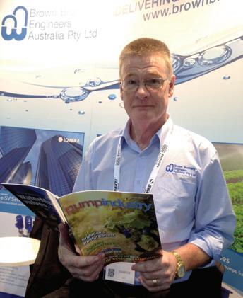
Our latest Pump Industry selfie comes from John Inkster, Chief Executive Officer of Brown Brothers Engineers Australia & New Zealand and Vice President of the PIA. John was spied reading his copy while doing the recent trade show rounds, which in our opinion is a great way to make use of the inevitable down time that happens when foot traffic quietens down at trade shows!

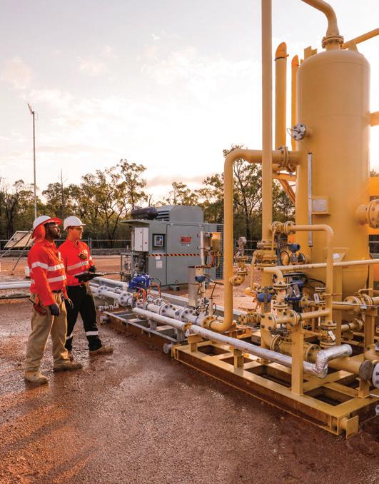
Production testing and fraccing operations at Strike Energy’s Southern Cooper Basin Gas Project in Queensland have been successfully completed and several pump systems have been upgraded.
Strike Energy Managing Director David Wrench said, “The productivity improvements we have seen at Klebb 3, and the fact that we have now successfully completed seven fracs in the Patchawarra coals are important milestones – they’re further confirmation of our confidence in the long term productive capacity of the field and our ability to commercialise it.
“We are looking forward to having all four Klebb wells working together to accelerate progress towards commercial gas flows.”
The performance of the wells since recommencement of testing had been consistent with previous production
ramp-ups and Strike was particularly pleased with the improved productivity of Klebb 3.
The upgraded pump systems were also operating well and had sufficient capacity to handle increased water rates.
Based on the success of the Klebb 3 workover and downhole jet pump equipment upgrade, Strike plans to implement the same modifications at Klebb 2.
The Klebb 4 fracture stimulation has also been pumped and the well is flowing back unassisted.
The electric submersible pump and control systems will be installed once the well has cleaned up with commissioning and extended testing on track to commence in early July 2016.
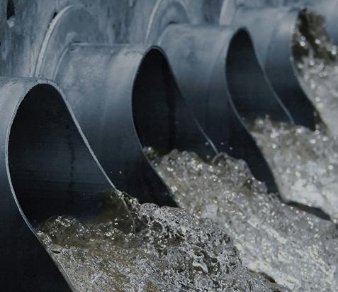
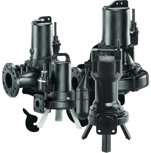
Anew pump station on Lake Road in Kyabram is now complete, despite several setbacks in the pump testing phase.
The project was carried out by Girdwood Constructions and involved the construction of three new pumps. All required infrastructure to monitor and control the pumps, as well as the decommissioning and removal of the original pumps.
A site cleanup was also completed to improve the appearance of the site and to allow better access to the new pump infrastructure.


We can replace up to 70% diesel consumption with gas That’s smart control



Shire of Campaspe spokesperson for Roads Ian Maddison said apart from the setbacks the project was completed well under budget.
“This has been a difficult site to develop. The basin and pumps are critical infrastructure that provide protection to the town when it rains. It was essential at all times that the basin and pumps remained operational until such time as the new pumps were constructed,” Mr Maddison said.
“Starting this work was not helped


InteliBifuel brings you a new level of control for dual fuel systems.
> Reduce OPEX
> Fuel flexibility
> Accepts a range of gas types
> Short ROI


> Minimise your environmental impact





due to rain over the first few weeks of the project as well as the discovery of a very soft layer where the new pump structure was to be built.


For a chance to win an iPad Mini, head to www.comap.com.au and visit our Bi-Fuel page


“When the new pumps were installed and the project reached testing phase, there was no water in the basin. It was essential to have as much water as possible in the basin to enable all the new pumps to be tested to their full capacity.”






Mr Maddison said this resulted in a period of several months during which the pumps couldn’t be tested, causing significant delays and pushing back the completion date.



“Thankfully we were able to test the pumps after May rains, and they have had a good test with further rain in May and June. I am confident these new pumps will serve the Kyabram community well into the future.




“We also made sure the older pumping systems were running while the works were happening in order to provide flood protection. This project had a lot of elements to it, all of which had to come together,” Mr Maddison said.

Hydro Innovations have introduced a new range of positive displacement pumps that make safety and maintenance a breeze.
The Ragazzini Rotho range of positive displacement peristaltic pumps have a “roller on bearings” design, so that the pump housing does not need to be filled with lubrication fluid. This makes them safer and easier to maintain, says Australian distributor Hydro Innovations. The pump is selfpriming, seal-less, can run dry without damage, and apart from the flanges, only one part comes in contact with the pumped fluid.
The Ragazzini range is self-priming and widely used in water and wastewater treatment, the food and beverage industry, the chemical industry, as well as in the construction, paper, ceramic, paints, inks, mining and marine industries.
Rotho pumps are available with a wide variety of hose options to suit abrasive and/or corrosive applications and are also available with food grade hoses capable of being sterilised with hot water (to 70o) and/or steam (to 120o). A leak detector is standard equipment to provide early indication of hose failure. This is a float type sensor that is located at the lowest point in the pump. Because of the speed of the leak detector, and the fact that the pump casing is not filled with lubricating fluid, contamination and product loss is greatly minimised.
Ragazzini peristaltic pumps are perfect for clean in place (CIP) or sanitise in place (SIP) applications when fitted with the optional “retractable roller”. With this system, one of the rollers can be retracted via an over-centre rapid release cam and lever system. This now enables full flow of a flushing/cleaning/ sanitising fluid through the hose. This new positioning system is essential for fully automated foodstuff handling applications that require regular cleaning

and sterilisation of all the components in contact with the product.
These pumps can deliver as little as 0.2 litres per hour and up to 180,000 litres per hour. Pressures to 15 bar can be achieved and solid particles can be passed through the pump. It can also be run in reverse, making it ideal for tank emptying and filling operations.
Ragazzini pumps do not need the casing to be filled with lubrication fluid. This reduces the chance of contamination, and makes hose changes cleaner, quicker, safer and cheaper.
Roller on bearing design minimises friction on the hose compared with the rubbing shoe method.


Xylem, a leading global water technology company dedicated to solving the world’s most complex water issues, has developed another breakthrough technology, launching the world’s first wastewater pumping system with integrated intelligence at the recent IFAT 2016 trade show in Munich, Germany.
Flygt Concertor, a smart, sustainable, interconnected solution, significantly advances the sustainability of the wastewater sector by offering unprecedented flexibility and reduced overall cost of ownership, while consuming considerably less energy and ensuring consistent, clogfree wastewater pumping. The system senses the operating conditions of its environment and automatically adapts to pumping conditions to deliver optimal pumping performance.
“Flygt Concertor is another example of Xylem’s commitment to developing innovative and integrated designs that can meet the current and future challenges of the industry,” said Tomas Brannemo, President of Xylem’s Transport business. “This revolutionary new solution represents a step-change in sustainable wastewater management solutions and is a real problem-solver, developed in close collaboration with our customers. Our recent report Powering the Wastewater Renaissance shows that the adoption energy efficient wastewater management technologies can dramatically slash electricity-related greenhouse gas emissions by almost half.”
There is a growing need for technology that optimises the performance and management of pumping systems. Ageing infrastructure, increased global urbanisation and rising energy costs make sustainable wastewater pumping systems an urgent priority. By 2050, 70 per cent of the global population will be living in cities – an urban wastewater challenge on a scale never experienced before. Frost & Sullivan’s report European Smart Pumps Market for the Water and Wastewater Industry notes that a sustained focus on energy efficiency and a reduction in the total cost of ownership of pumps are likely to lead to increased demand for intelligent pumping solutions. Flygt Concertor can help address these complex challenges in a sustainable manner.
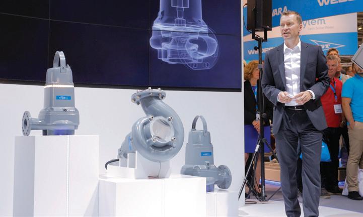
Fields tests conducted around the world have validated significant benefits that Flygt Concertor delivers including:
• Energy savings of up to 70 per cent compared to a conventional pumping system by consistently operating at the lowest possible energy level.
• Reduced inventory of up to 80 per cent due to flexible performance –the system self-adjusts or can be adapted to suit different conditions, without changing the impeller or motor size. This versatility eliminates the need for pump station managers to keep large inventory stocks.
A built-in sump and pipe cleaning function – a world first for a wastewater pumping system delivering clog-free pumping and clean wet wells saving up to 80 per cent in vacuum cleaning costs.
Compact design, reducing cabinet size by up to 50 per cent compared to conventional designs.
Xylem is committed to developing technologies that advance the sustainability of wastewater management systems. For example, Xylem’s recently launched Flygt 4320 mixer with integrated speed regulation optimises operators’ control over the
mixer’s thrust, enabling consistent process results and reduced energy consumption. It is a high efficiency, low-speed, submersible wastewater mixer that can help reduce energy costs by as much as 50 per cent.
Flygt Concertor and the Flygt 4320 mixer share a rich heritage with other Flygt innovations. The brand is renowned as a market leader in the design of advanced water and wastewater solutions with a 100 year legacy of innovation in pumping, from developing the first submersible pump to designing the non-clogging N-impeller.
The name Concertor is derived from the Latin “concentare”, meaning “working together to orchestrate harmony”. Flygt Concertor combines IE4 motor efficiency, N-hydraulics, integrated power electronics and intelligent controls that work in harmony with each other, resulting in optimal pumping performance at the lowest cost of ownership.
Flygt Concertor will be available in Australia and New Zealand from early 2017. For more information, visit flygt.com/one-ultimate-system.
VISIT US AT THE WIOA VICTORIA
CONFERENCE &
EXHIBITION:
STANDS 130 & 147.

THE ULTIMATE SOLUTION TO REDUCE TOTAL COST OF OWNERSHIP
Prepare to experience a whole new level of wastewater pumping. Xylem will soon be launching a revolutionary and integrated new technology that will redefine the wastewater industry. It combines everything we know about meeting your toughest wastewater challenges to significantly lower total costs.
To find out more, visit us at www.flygt.com/one-ultimate-system
www.xylem.com/pumping
Right price, right place, right now! This may be the simple ‘scope of supply’ at any given time or in the heat of the moment, but what other responsibilities come along with a willingness to supply?

It’s apparent that historically it was easier to sell to the larger industrial sites and councils than it is today. Typically there used to be a clearly definable engineering infrastructure, usually led by an experienced engineer, where the scope of supply was articulated in a series of (consistent) specifications, procedures, and standards that challenged you to conform with and which in turn granted you eligibility to supply. Essentially, there was someone in place to ensure product performance and overall system integration into the plants needs and processes. That was a win-win, and that’s the way we all liked it!
As costs were ripped out and outsourcing became the creative accountants mode of operation, the removal of local and site engineering not only saw site specific intellectual property vanish overnight, but along with that came a massive (but not so obvious) shift in responsibilities to the original equipment manufacturer (OEM) and manufacturer. No longer was there a guardian of the site that held you to account through the compliance requirements.
What also came along with this more traditional process were obligations that didn’t need prescribing. Manuals, commissioning and maintenance training were all usually supplied willingly and freely as part of the scope of supply. Combined with that, ongoing services such as spare parts availability and technical support were unconditionally included, basically because you wouldn’t dare turn up to try and sell something else if previously supplied products
weren’t performing to site expectations. Hand in hand with this ‘localisation’ came the commercial rewards that made it possible for OEMs and manufacturers to maintain local services that brought benefits in plant design, plant performance, and plant reliability.
While specifications still abound, many scenarios today see a cut-copy-paste effect where compliance rates vary, where opportunities for genuine quality and broader based value propositions have no platform to be presented (or assessed) on, and where longer term obligations of product support, as in after sales services (spare parts etc), can easily be bypassed by cheaper ‘imitations’, at the expense – both short and long term – of the site.
The difficulties don’t only manifest themselves on the supply side. If and when things go awry, it can be extremely difficult to identify just who is in control at any given time. Invariably, managing and defending your brand reputation can become extremely difficult and expensive in times of crisis, whether the crisis be actual or perceived. Having a clearly articulated scope of supply may be the only fall-back position you have to rely on when these events occur, providing a practical line-in-the-sand which in turn provides a basis for moving forward.
Ensuring you qualify your scope of supply may just be the difference between enjoying the rewards of a nice job or facing a financial disaster.

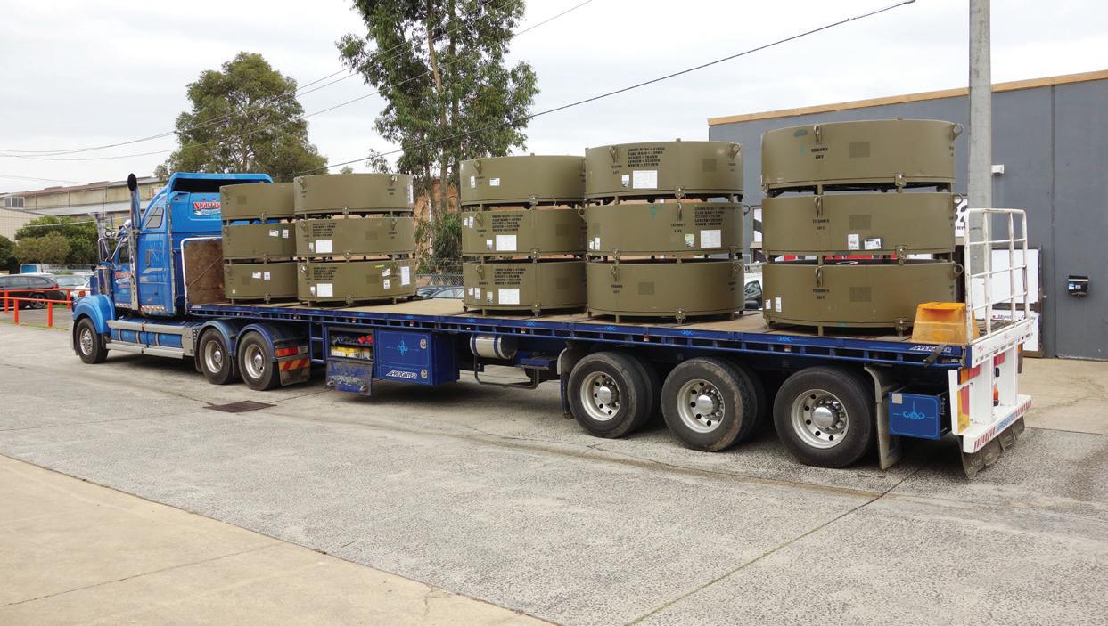
Most of us won’t spend much time thinking about the logistics of fuel transfer and supply for the Australian Defence Forces (ADF), currently active in a number of countries around the world. But for one Australian company, this very topic has been a focus for a number of years, ultimately providing the ADF with an innovative method for fuel distribution.
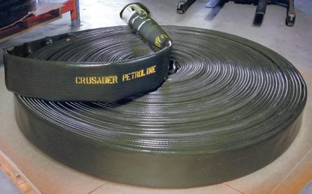
Melbourne-based Crusader Hose are the manufacturers of the Petroline hose. This product has recently been used by the ADF for fuel transfer at overseas locations. For the ADF and their staff, who often move quickly between locations - yet still need a regular and consistent source of fuel - building a permanent fuel line to a set location is not a possibility, due to time and construction constraints.
The need for a temporary solution, which can be easily deployed to the battlefront, led the ADF to investigate options such as layflat hoses, so that they have the capability to transport fuels between constantly changing locations.
“The appeal of Petroline for the ADF lies in the fact that it provides a rapid and compact solution for the transportation of fuels,” said Crusader Hose Managing Director Francois Steverlynck.
“As a military deployment, the army needed the flexibility and maneuverability of the flexible layflat hose, often over rough terrain and over significant distances.
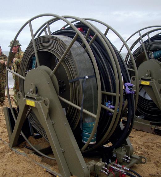
“The fuel hose reel systems were essentially modular in design, allowing for easy deployment and retrieval, at the completion of that particular mission.”
Additional factors central to the success was the fact that
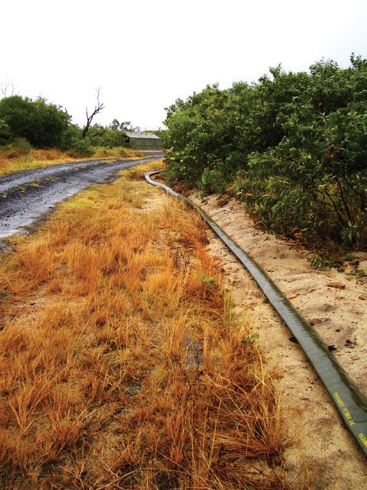
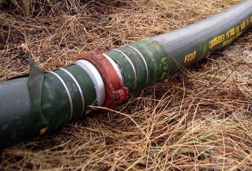
Petroline is a lightweight, easily handled and stored fuel hose of high pressure rating. The polyurethane cover also provides chemical and abrasion resistance, plus UV stabilisation.
In securing the ADF contract to supply Petroline, Crusader Hose overcame stiff competition from international suppliers, to reach the demanding standards set by the ADF.
Since securing the initial supply contract, the Petroline hose has risen to the occasion and performed successfully in service. As a result, the ADF has since placed several more orders with Crusader Hose.
As well as the compact nature of the solution, the ADF was also impressed with the product’s ability to pump fuels over long distances. By using Petroline, the ADF has eliminated the need to truck fuels large distances, which has obviously provided a rapid maneuverability benefit to the front-line troops.
As part of this contract, Crusader Hose also developed a purpose built hose reel system that can be easily deployed in the field to lay the fuel transfer hose. Portable reels capable of each holding 800m of layflat Petroline were designed and built to exacting specifications.

Government investment in Tasmanian irrigation is creating economic growth and new job opportunities across the state.
Reid Fruits at Jericho is one of the local businesses benefiting from increased irrigation investment, using an investment of $1.13 million to expand its orchards and employ an additional 30 people.
Reid Fruits will soon begin planting its first cherry trees at Honeywood Orchard in the Southern Midlands, which is traditionally dry grazing land.
Tasmanian Minister for Primary Industries and Water Jeremy Rockliff said having 95 per cent reliable water available through Tasmanian Irrigation schemes was unlocking new opportunities.
“Generations before would never have believed that we could turn this grazing land into a cherry orchard, yet that’s what’s being achieved through irrigation,” Mr Rockliff said.
“Reid Fruits’ investment and expansion will create 30 full-timeequivalent positions when it’s operational and as many as 200

positions in the peak of the picking season.
“The unique elevation of the site will also extend harvest time beyond that at any other orchard, allowing Reid Fruits to tap into the lucrative Chinese New Year market unlike ever before.
“We look forward to seeing other agricultural projects expand just like Reid Fruits as we progress the five Tranche 2 Schemes, made possible
with $60 million from the Federal Liberal Government and $30 million from the Hodgman Liberal Government, and investment from farmers.
Tasmanian Federal Liberal Member for Lyons Eric Hutchinson said “It’s clear that the water provided through our investment in irrigation is transforming not just our landscape, but also our agricultural sector’s capacity to grow, invest and create jobs.”



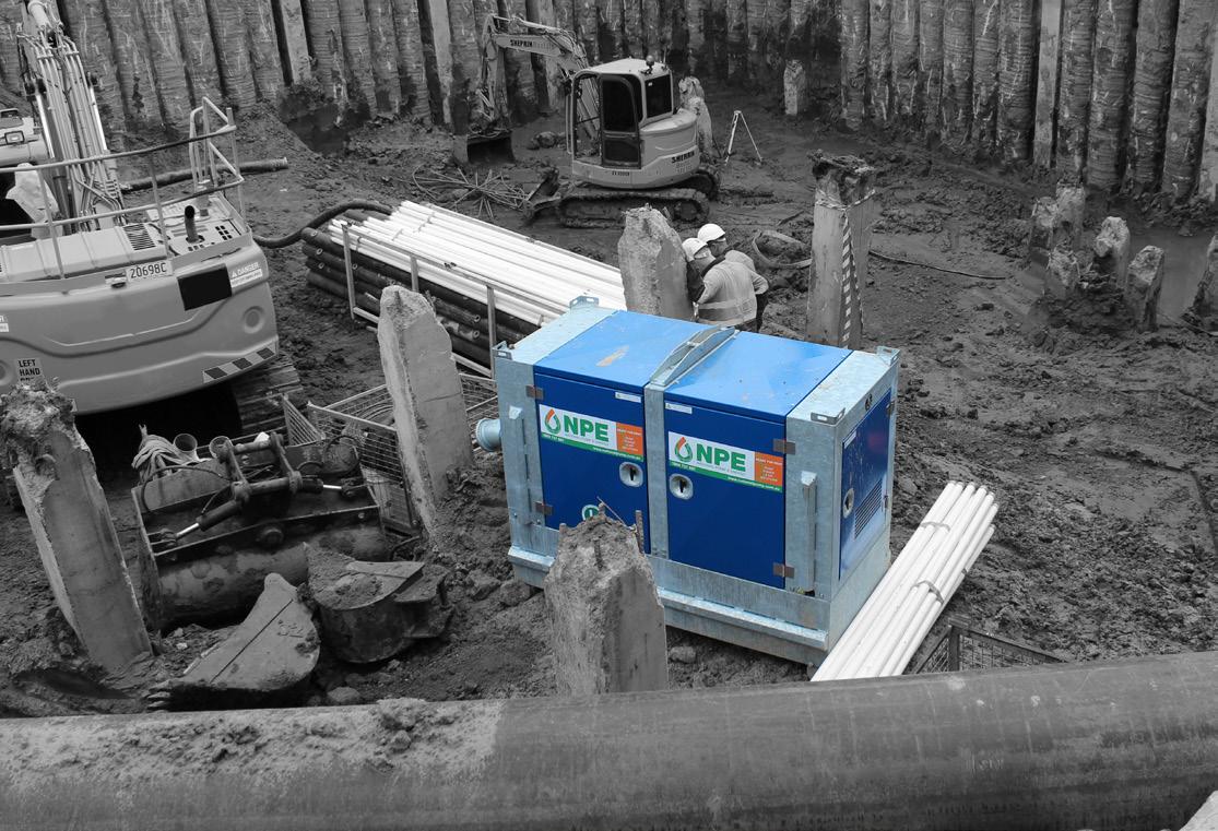
Leading pump supplier National Pump & Energy (NPE) has signed a new deal as the exclusive Australian supply partner of a world renowned pump manufacturer.
NPE will be the exclusive supplier of BBA Pumps across Australia. With a solid history of providing pumping solutions to the Australian market, this latest development further strengthens NPE’s place as a market leader.
Under the terms of the agreement, NPE will be the sole supplier of the entire BBA range of market leading pumps and parts through their Australia-wide network of branches.
BBA Pumps Managing Director Roland Berns said that they are extremely happy with the deal and look forward to partnering with NPE.
“NPE was selected based on its commitment and dedication to providing quality products and services in each of the markets in which we operate,” he said.
“The Australian market is very important to us and partnering with a national supplier with a strong
reputation for quality, such as NPE, reflects BBA Pumps commitment to providing our customers with an exceptional experience,” he said.
Having had many years’ experience in supplying pumping equipment to the Australian market, Rod Hayes, Managing Director of National Pump & Energy, is pleased with the addition to the company’s extensive fleet of specialist equipment.
“The BBA Pumps are class leading in their design and performance” he said. “We are thrilled to be associated with BBA Pumps and look forward to providing the Australian market with these terrific pumps.”
The BBA range of contractors pumps, piston pumps and trash pumps are more often than not the professional’s first choice for a quality, reliable pumping solution.
NPE will stock the range of pumps for hire or sale from their branches throughout Australia.
Products and services now offered by the amalgamated company now range from everything from pump

hire, pipeline construction and water management, right through to generator hire and continuous power systems.


Keeping settling ponds in optimum condition without taking the sewage plant offline represents real cost savings. Dredging Solutions from Sydney NSW are now able to offer this option due to an innovative application of a Tsurumi submersible cutter pump.

While dredging ponds for Sydney Water, the company was faced with pump chokes caused by accumulated rags. Normal submersible pumps cannot cope when oversized, fibrous materials get flushed into the system. Dredging Solutions turned to Aussie Pumps for a suitable cutter pump to solve the ragging problem.
Tsurumi, the world’s leader in submersible pump development, has produced a range of cutter pumps, called the C Series, designed to handle such contaminated waste. The C series cutter pumps chop waste material, including rags, thus allowing free passage through the pump without clogging.
“Tsurumi’s breakthrough cutter impeller chops through sewage, rawhide, plastic, rags and other materials in seconds,” said Aussie Pumps Product Manager Neil Bennett. “We’ve seen various unmentionables handled by these extraordinary pumps, so they were an obvious choice for Dredging Solutions’ ragging issue,” he said.
The C Series incorporates a large
open channel impeller with a cutter mechanism. A sintered tungsten carbide alloy tip is brazed on the impeller vane. As the impeller rotates, the vane slices against the serrated edge of the suction cover, chopping fibrous matter into small fragments that won’t clog.
The three phase, heavy duty pumps range from 50mm bore to 100mm. The largest pump in the range has an enormous capacity of 2,750 litres per minute, and a max head of 26 metres.
“There is a terrific video on YouTube that shows the pump’s cutting ability. It’s amazing to watch what these unique cutters will do. You’ll never believe it until you see it,” said Bennett. “The demo even shows the pump swallowing nylon rope,” he said.
Like all Tsurumi submersible pumps, the C Series include features that extend the life and enhance reliability of the pump. Significant design details make a big difference. They include an anti-wicking cable entry that prevents water from entering the motor if the power lead is damaged or the end of the cable is accidentally submerged.
A double silicon carbide seal is


standard on all models. Both seal surfaces are submerged in an oil chamber, away from the pumped liquid. This ensures lubrication and protects ingress of foreign materials.
The oil bath features a patented “Oil Lifter” that increases mech seal longevity. The lifter ensures both the upper and lower seals are lubricated and cooled, even if the oil level in the chamber is low.
“We have created a bit of a buzz within Sydney Water with how well the new system is dealing with the rags on site. They have a lot of the ponds to dredge at one time or another, that are heavily ragged up and we now have a solution to deal with it,” said Cameron Lorimer from Dredging Solutions. “The cutter pump coupled with our dredge system will allow the cleaning of the ponds while they remain online. This is critical to the ongoing operation of the plant,” he said.

Further information on the complete range of Tsurumi
pumps is available on the Aussie Pumps website (www.aussiepumps.com.au) and from Dredging

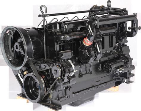

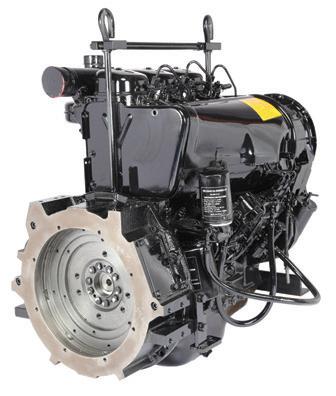
• Direct Injected
• Air Cooled

• Indifferent to Climatic Conditions - Rugged engine suitable for any harsh climatic conditions
• Sensibly priced
FOR




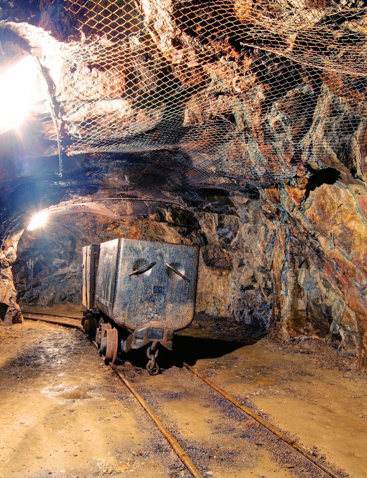
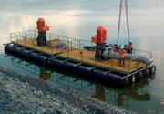
Naturally occurring groundwater in Bendigo’s historic gold mines has been rising and threatening water quality and surrounding infrastructure for many years– but there are solutions. The Department of Environment, Land, Water and Planning (DELWP) recently contracted the Bendigo Trust to dewater the mines until a permanent solution is found.
In early 2015, groundwater from historic mines in Bendigo, north west of Victoria, began causing odours along Bendigo Creek, impacting local water quality and resulting in small surface discharges.
That is why Bendigo Trust, the operators of the Central Deborah Tourist Mine, have been contracted to pump the groundwater out of the mines. This mine dewatering aims to stop the levels getting too close to the ground surface and contaminating local waterways.
Due to the region’s geology, the water from the mine voids (the excavation area that remains after mine rehabilitation) contains increased salinity, arsenic, hydrogen sulphide (causing a ‘rotten egg’ smell) and other heavy metals. The poor quality of the water has the potential to impact infrastructure such as underground utilities, road and building foundations, as well as cause soil salinisation.
The immediate solution to this problem involved pumping the groundwater from the Central Deborah tourist mine to the New Chum line of workings via the Eureka shaft, but this work was stopped in late February 2016 due to the pending transfer of mining and exploration licences for the Bendigo gold fields.
Then, from early March, groundwater was pumped to the Garden Gully line to ensure the Bendigo Trust could continue their business without disruption.
In May, the Victorian Government approved the transfer of mining licences in Bendigo from Unity Mining to Kralcopic. The transfer of the mining licences enabled DELWP to enter into negotiations with Kralcopic to resume pumping the groundwater from the Central Deborah shaft to the New Chum line via the Eureka shaft, and pumping resumed in June 2016
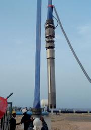
Contractors Bendigo Trust pumped the groundwater using Grundfos SP 95-20 pumps. Two pumps were installed


to provide redundancy in the project and to allow pumping at a higher than normal rate when required. These fully submersible pumps consisted of a 95kw pump motor and 20 pump stages in the wet end.
The submersible pumps were chosen because they met the specific technical requirements of pumping the groundwater, which was a head pressure in excess of 260 metres and a required maximum volume of two M/L per day, per pump.
Besides the technical requirements, the pumps were also chosen based on the constraints of the project, which included the short lead time Bendigo Trust had to get the system installed, as well as the ease of acquiring spare pumps and parts, the cost, and the reliability of the pump units.
Even with all this in mind, there were still major challenges involved in installing these large pumps into the confines of the mine shafts.
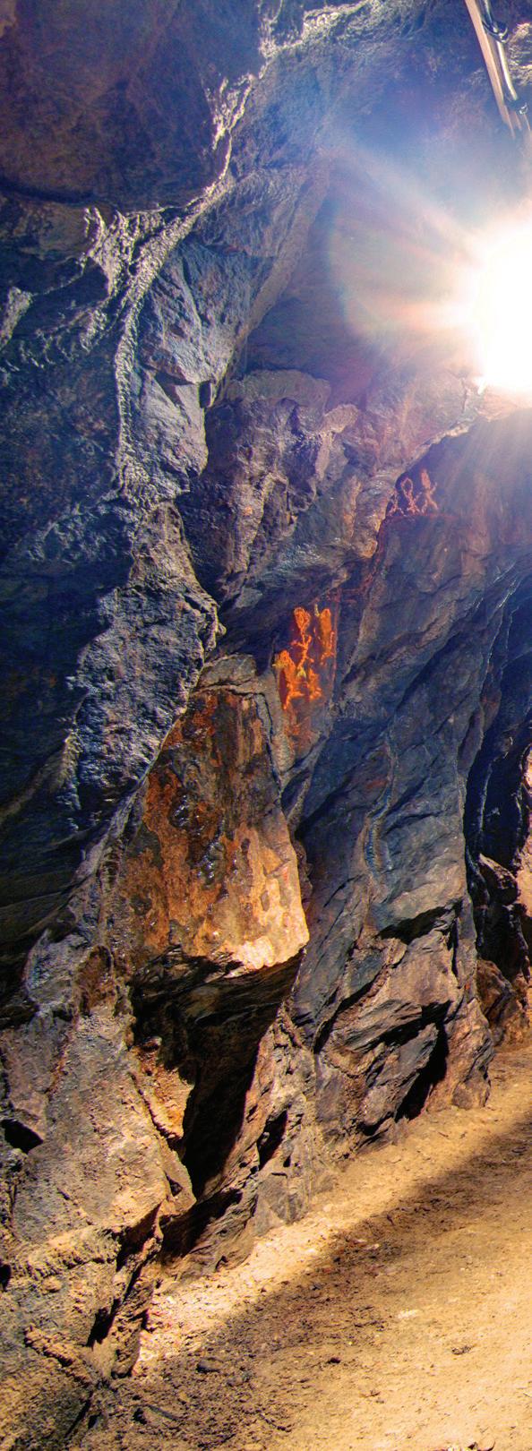
At the Central Deborah mine, there were difficulties regarding the installation and maintenance of the pumping infrastructure so very specialised engineering solutions had to be devised to allow for installation into the timber mine shaft, which was located approximately 260 metres below the surface.
Since there was no access for heavy machinery or heavy lifting equipment, most of the preparation and installation work relied heavily on devising one-off solutions and using equipment such as hand-held jack hammers to carry out excavations in the rock and allow installation of the necessary components.
DELWP has since been searching for a backup pumping point to divert the groundwater from the mines, with one potential short-term solution involving uncapping the former Specimen Hill

mine shaft in Eaglehawk.
DELWP investigated the old shaft at Specimen Hill to see if it would be a suitable extraction point for pumping the groundwater from Bendigo’s disused mine shafts to Coliban Water’s Reclamation Plant at Epsom for treatment.
While there is no immediate threat from the contaminated water, the uncapping works of Specimen Hill mine were undertaken to identify viable options to divert the groundwater while the transition option is in place.
This transitional solution with the Epsom plant involves implementing
processes and infrastructure that could then be used within the permanent solution, once one is found.
The uncapping of Specimen Hill involved drilling a 300 millimetre diameter hole into the concrete shaft cap and assessing the shaft condition. After the assessment, Bendigo Trust submitted a report to DELWP on the mine’s suitability to be used as part of the transitional solution, but unfortunately the report showed the mine had collapsed timbers and backfill creating a ‘choke’ in the shaft. Removal of the choke would require considerable effort and cost.
Taking these factors into account, planning is now under way to see if the Suffolk and Argus mines would be more suitable sites to pump the groundwater.
The 2016-17 Victorian Budget includes a further $14 million of funding to enable implementation of this transitional plan, based on the pumping and treatment of groundwater at the Epsom Treatment Plant. DELWP is also working closely with the community and local government to develop future options for Bendigo’s rising groundwater problem.



The pump industry relies on expertise from a large and varied range of specialists, from experts in particular pump types to those with an intimate understanding of pump reliability; and from researchers who delve into the particulars of pump curves to experts in pump efficiency. To draw upon the wealth of expert knowledge the Australian pump industry has to offer, Pump Industry has established a panel of experts to answer all your pumping questions.

QUESTION: We often hear that progressive cavity pumps are extensively used in the mining industry. What are some of the common applications where these pumps are most suited?
ANSWER:
Our progressive cavity pump expert is Peter Vila, Managing Director of SEEPEX Australia. Peter has been involved with pumps for 35 years. He spent the first five years repairing them and the subsequent 30 years directly in technical sales, and for the past 15 years he has been predominately involved with SEEPEX progressive cavity pumps.
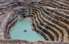
Open-cut mine.
It’s correct that progressive cavity pumps are very common on mine sites throughout Australia. In fact, this particular market sector would be on par with water/wastewater, as one of the most popular for PC pumps in Australia. To list in detail the various applications would take up this entire magazine issue, so instead I have summarised the following typical applications and the key benefits of this pump design.

Mining methods.
Mine types where progressive cavity pumps are used in Australia:
• Bauxite (also refined alumina)
• Coal
• Copper
• Gold
• Iron ore
• Mineral sands
• Nickel
• Shale oil
• Tin
• Uranium
• Vanadium
• Zinc
Also used by countless suppliers of mining equipment and chemicals for:
• Decanters and centrifuges
• Tunnel drilling equipment
• Flocculants
• Chemical dosing
• Liquid explosives

Common applications for progressive cavity pumps in mining:
• Transfer of mineral slurries
• Void back-filling applications
• Dosing of explosives
• Thickener underflow applications
• Centrifuge filling
• Chemical dosing
• Water treatment
• Cake transfer
• Leachate treatment
• Gland water supply
• Sludge feed to dewatering machines
Typical transfer liquids include: polymers, sludges, slurries, grouts, various chemicals, clean and dirty water.
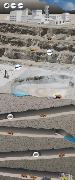
Mine dewatering applications for progressive cavity pumps:
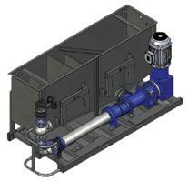
This is probably one of the most common areas where progressive cavity pumps can be seen, usually installed on a
transportable skid with collection tanks for incoming water, and generally incorporating some kind of solids separation to partially clean the muddy, high sediment mine water. The range of progressive cavity pumps used for these applications can be quite long in length, due to the pressure generation required for pumping to the surface from several hundred metres underground. There are several companies currently who specialise specifically within this application sector and occasionally there can be new design developments which may give significant benefits to the users of this product range. Keeping oneself abreast of these developments can certainly pay significant dividends to mine operators. More detailed information on specific design developments can be requested via the contact details at the end of this article.
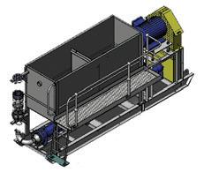
• Self-priming
• Non-pulsating flow
• Valveless operation and flow control
• Reversible for back-flushing
• Flow proportional to speed
• No day-to-day maintenance required
• Versatile, can be installed horizontally, vertically and virtually any position
• Minimal flow drop against changing pressures
• Ability to handle multi-phase fluids (liquid and gas)

For more information on progressive cavity pumps for the mining industry, please contact SEEPEX Australia on (02) 4355 4500

Alberto Caprari Chief Executive Officer, Caprari Pumps
Alberto Caprari is the Chief Executive Officer of the Caprari Group, headquartered in Italy and with posts around the world, including here in Australia. The Caprari Group was established 71 years ago, and has been focused on the manufacture and production of centrifugal pumps and electric pumps. The group is also focused on the creation of advanced solutions for management of the integrated water cycle, and other professional sectors including oil and
gas, power generation, mining and industry.
Caprari’s continuous research is aimed at manufacturing products that are sustainable, both in respect to the materials used and the energy that is ultimately used by their products.
Mr Caprari was recently named President of ANIMA, Confindustria’s Federation of Italian Associations of Mechanical and Engineering Industries. ANIMA is one of Europe’s most important and well-established organisations, comprising 34 associations and over one thousand member companies. Numbering over 194,000 employees and with

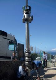

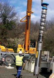


Last year we took a closer look at some of the people and personalities that make the Australian pump industry tick in our inaugural ‘Pump People’ feature. This year, we’ve spoken to a new crop of leaders in the industry to learn about their careers in pumps, their current roles in shaping some of the key players in the Australian pump industry, and where they see the future for the industry heading.
€40 billion revenue, the mechanical engineering industry is the backbone of Italian industry as a whole, and Mr Caprari’s appointment as President is reflective of Caprari’s significant involvement in the sector.
For Mr Caprari, the ongoing impact of globalisation is something he and the team at Caprari Pumps are constantly taking into consideration.
“We definitively believe that the globalisation process has now clearly transformed into more of a ‘global’ approach - we need to think globally but act locally.
“A successful pump company like Caprari must continue to adapt itself to the new challenges that changing markets impose, while strongly leveraging on its own precise identity.
“We are a family-owned Italian company, established by Amadio Caprari 71 years ago, and today we have more than 15 facilities, including subsidiaries and manufacturing plants, around the world. Together with our 700 employees, we are fully committed to tackling the new challenges of the global pump marketplace: system approach, total cost of ownership, the internet of things and new pump applications. In doing this, there’s always an awareness of emerging global markets, and constant changes to the geopolitical map.
“We’ve really developed our worldwide presence in order to be closer to our customers and pump end users, and we always operate with our values of loyalty, integrity and innovation at the front of mind. For Caprari, the focus is on strengthening business relationships with our partners and ‘bringing more quality-water around’.”
It’s this focus that Mr Caprari, and the Australian arm of the group, bring to their operations Down Under - which the group predicts will continue to grow in the coming years.
“We predict that Australia, in the long run, will keep growing as a country that’s attracting people both from western countries and also from China and Southeast Asia,” noted Mr Caprari. “Newcomers that are willing to make local investments and participate in the development of either the primary or tertiary sectors, such as agriculture, food and dairy, plus education, tourism, and health care, will be successful.
“This will also positively affect infrastructure networks and building services, which are the market sectors where Caprari is able to offer hightechnology pumping systems and solutions.”
For Mr Caprari, he loves the diverse nature of being involved in the pump industry in Australia.
“In my view Australia is just the world, compacted. Almost every culture is represented today Down Under,” said Mr Caprari.
“We certainly love the fact that Australian professionals involved in the water and pump industries are appreciating new technologies and quality solutions, and the fact that they look for good, solid companies to work with.
“Australian companies never take a superficial approach, they look at the broader implications of the challenges they face and together, we create new solutions that meet their pumping needs.
“It’s the quality professional
environment, and the long-term market potential, that has led us to recently to further invest in Oceania, becoming last November 2015 the full owners of Caprari Pumps Australia and Caprari Pumps New Zealand.
“As part of this move we’ve adopted a business plan for the next few years that will include consistent investments, in order to increase customer satisfaction and therefore market shares.”
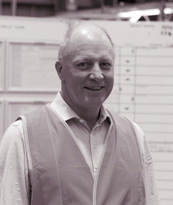 David
Chief Executive Officer, Davey Water Products (Global)
David Worley is the Chief Executive Office of Davey Water Products – a multi-national manufacturing company headquartered in Melbourne, Australia and owned by the GUD Group.
Mr Worley is a relative newcomer to the pump industry, joining Davey in 2013. He is an experienced operating CEO and has significant building industry and manufacturing experience, having
spent 17 years in a range of senior leadership roles across a spectrum of manufacturing and distribution businesses.
With a number of the businesses he has joined (ranging in size from $100 million to $2 billion) performing sub-optimally, Mr Worley has applied a combination of strategy development and business fitness improvement to improve their performance – a strong theme in the last 15 years of his career in particular.
Headquartered and a market leader in Australia, Davey manufactures and distributes a range of products which transfer, conserve, treat and filter water to over 50 countries where they perform in some of the world’s toughest conditions.
With a focus on new and smarter ways to help customers solve problems and its strong engineering capability, Davey develops and markets leading water products for homes, businesses and farms, fire and flood protection, rainwater harvesting, swimming pool and community needs.
Mr Worley is particularly excited to bring his unique skill set to Davey, and the broader Australian pump industry, in the current challenging environment.
“With the market looking fairly flat and no immediate prospect of
substantial market growth, in order to thrive, companies will have to get better at doing the basics – looking after customers, setting high standards of delivery and service, and constant product improvement – at an economic cost,” said Mr Worley. “And it’s not just about looking after customers, but properly understanding their needs and helping them to grow their business by understanding what works for them in their local markets.
“In our particular market, to thrive we need to anticipate industry changes and recognise that water is becoming an increasingly important resource that is not always going to be available at the quality or cost that people prefer or have become accustomed to – even in the major metropolitans.”
Like many in the industry, Mr Worley expects that while challenging market conditions prevail, we’ll continue to see more merger and acquisition activity in the industry both locally and globally.
“I expect to see some level of industry consolidation - particularly in distribution channels and how we get products to customers,” said Mr Worley. “We will continue to see the increasing impact of the internet, which will also have a significant impact on how we get products to customers.
“I think the pump industry has
held a belief that, due to the technical complexity of what we do, our products and services don’t lend themselves to an ‘online’ or self-service environment. But people are smart and inevitably more and more of what the industry has to offer will be available on the internet directly for consumers.”
While his time in the industry has been brief, Mr Worley has already identified some of the key factors that make it a great place to work.
“It’s an industry that has operated on traditional lines which, if carefully managed, provide an opportunity for innovation with a vitally important commodity – water,” he noted. “And from a Davey Water Products perspective, it’s exciting to have the opportunity to protect and enhance people’s lives with water.”
Steve Bosnar is the Managing Director of Pioneer Pump Australia, a leading edge US pump company based out of Victoria. Mr Bosnar has been in the pump industry for over 30 years and has a deep knowledge of the current state of play.
For Mr Bosnar, challenging market conditions have provided opportunities for growth in new areas.


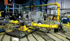
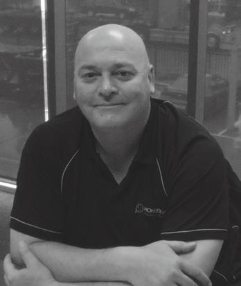
“The industry that we share is one that’s had its challenges, particularly over the last four years,” said Mr Bosnar. “The downturn in the mining and oil and gas sectors has had a huge influence on our local economy, and our industry has not been immune.
“For us, like most that are still in the pump industry, we had to adapt to the changes in this economic environment. We have had to diversify into other markets, introduce innovative new products, whilst continuing our aim for greater share of our traditional markets. We have also increased our footprint further into Southeast Asia and the Oceania, which has helped us find new markets and grow.”
According to Mr Bosnar, the performance of the broader Australian economy will continue to have impacts on the Australian pump industry.
“As today’s market uncertainty continues, our industry, like most, fluctuates with Australian Commodities,” said Mr Bosnar. “If the markets are taking a beating, so are we through the flow on.
“Analysts predict that certain commodities will firm and slightly strengthen by the end of 2016. The strengthening is suggested to continue throughout 2017 and more so in 2018. If this prediction is correct, I suggest that the pump industry should see the benefits mid to long term.”
Like many industries, the pump industry is a cyclical one, but for Mr
Bosnar, one thing that remains constant is his enjoyment at being involved in pumps.
“This is an industry that some of us are passionate about,” said Mr Bosnar. “I started when telex machines were the preferred method of communication with suppliers! With over 30 plus years in the pump industry, I have made an enjoyable and fulfilling career. I have made lifetime friendships worldwide because of it, and I love the fact that I’m still learning and meeting new people everyday.”
John Shanasy, the Managing Director of Pump Power, began his career in the pump industry with an apprenticeship in instrument making when he was seventeen, before going on to study electrical engineering and graduating as an electrical engineer in 1975.
In 1978 he landed his first job in the pump industry, with Link Pumps. Mr Shanasy worked there for seven years in the technical and sales areas, providing a very good foundational knowledge and experience with a wide range of pumps. After a few years Mr Shanasy became the General Manager of Link Pumps, and in 1988 he acquired the sales division of the business and renamed it Pump Power Australia. Situated in Brooklyn, the business has been wellplaced to service the industrial areas of Melbourne, as well as developing markets throughout Australia and New Zealand.
A key value for Pump Power has always been to develop good personal relationships with both suppliers and customers. This goes along with expert technical knowledge and an emphasis on prompt and professional service. According to Mr Shanasy, Pump Power has always been ready to go the extra mile to help customers out of a tight spot.
In 2015, Mr Shanasy’s son Will and his wife Belinda took over the reins of Pump Power. Mr Shanasy said they are committed to the DNA of Pump Power, and to long-term suppliers

and customers. At the same time, Mr Shanasy said it is also rewarding for him to see a new generation introducing healthy innovations and new products.
According to Mr Shanasy, while the market conditions for the pump industry as a whole are currently challenging, some sectors of the industry have remained somewhat unaffected.
“Current market conditions have not changed dramatically for high-end and specialist pump products,” noted Mr Shanasy. “The change has been in the cheaper and simpler product ranges, where it has become all about price. It will be important for specialised pump companies to keep abreast of new technologies and maintain their technical edge. This will differentiate them from the crowd and enable them to be known for appropriate pump selection in technically complex situations.
“I also think that there may be an increased demand for pump system packages rather than individual pumps. Pump companies can adapt by gearing up for this.”
Mr Shanasy also believes that the ongoing focus on energy efficiency and whole of life costs will have an impact on the industry moving forward.
“In the short to mid-term there is likely to be an increased emphasis
on pump efficiency so less energy is consumed and costs are reduced. This shift is in the context of an increasing global focus on energy efficiency.
“As larger companies, whose business involves the use of pumps, focus more and more on core products and become less inclined to be involved with peripheral equipment, they will turn more to service providers like pump companies. There is therefore an opportunity for pump companies to get more involved in servicing and monitoring pumps. For the clients
it means less employee time spent on maintenance, and with wellthought-out pump monitoring, costly environmental spills are less likely.”
After a long and varied career in the industry, the part that Mr Shanasy has always enjoyed most has been the connections he’s made with clients and colleagues.
“The aspect of my career in the pump industry I have always enjoyed the most is the people. Having been

relationships with customers, suppliers, and the people at Pump Power.
“Being a practical person, who started off as an apprentice, I have also always enjoyed the hands-on aspect of working with pump systems. Whether it was working down a mine, or in the bilges of FPSOs, I welcomed the variety and the opportunities to get my hands dirty and not always be stuck in an office. The problem-solving required for complex pump applications has always






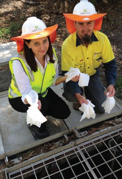
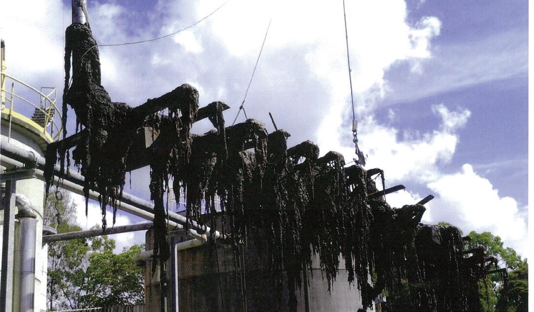
Across Australia and the world, water utilities are witnessing an increase in faults caused by non-degradable materials entering sewer networks. Many of these issues can be largely attributed to wet wipes, which do not readily disintegrate when flushed down the toilet, despite many brands being advertised as ‘flushable’. While the role of wet wipes in the creation of ‘fatbergs’ has received substantial media attention, wet wipes can also cause significant and costly damage to vital pumping infrastructure. We spoke to a number of water utilities across the country about some of the wet wipe-related issues they’ve experienced in their networks and what they are doing to protect pumps, fight fatbergs and combat the wet wipe menace.
Wet wipes are a significant problem for Sydney Water. Keiran Smith, Manager Media and External Communications, and Charlie Kawtal, Systems Operations Officer, told Pump Industry that in the past two years alone, Sydney Water has removed over one million kilograms of wipes from its network at an annual cost of over $8 million. Nationally, water utilities are spending over $15 million annually to remove wet wipes from their networks.
“If the wipes removed from the Sydney Water network each year were placed end to end they would stretch from Sydney to Los Angeles,” said Mr Smith.
“Wet wipes pose an environmental risk from overflows resulting from pumping station and overflow blockages, causing environmental and aesthetic issues in our creeks and waterways which are costly to clean up.
“As well, there is a safety risk to maintenance technicians and treatment plant operators who are required to clear wastewater blockages and filter screens.”
However, ‘flushable’ wipes can also create problems for customers before they even enter the larger wastewater network. They can also block household plumbing, causing overflows inside the home and costly plumbing bills.
Sydney Water reports receiving an increasing number of notifications from customers and private plumbers about problems being caused by wet wipes in private sewer pipes. One plumber claims that one in three of his call outs are the
result of blockages caused by wipes, and one customer reported a plumbing bill of $16,000 to repair damage to her property’s plumbing caused by wipes.
“In many areas about 75 per cent of sewer blockages will have wet wipe materials either directly or indirectly responsible for the blockage.”
Sydney Water first identified its wet wipe problem due to an increased frequency of issues caused by non-biodegradable materials in its wastewater network.
“The problem with wet wipes was initially detected due to the increased dredging frequency of the wet wells in Sydney Water’s pumping stations, as the result of the build-up of wipes,” said Mr Kawtal.
“There was also an increasing trend in faults at sewage pumping stations across the network. The cause of these faults was again largely attributable to the increasing disposal of non-biodegradable wet wipes via the wastewater system. Further investigation revealed it was an escalating issue for water utilities around the world.”
According to Sydney Water, there are two main areas in its wastewater system where wet wipe blockages are likely to occur – small diameter reticulation pipes and pumping stations.
Small diameter reticulation pipes usually have low flow. In addition to causing blockages directly, wipes can combine with tree roots or other minor obstructions within the pipes to cause blockages.
At pumping stations, wipes can get caught in the pumps, causing
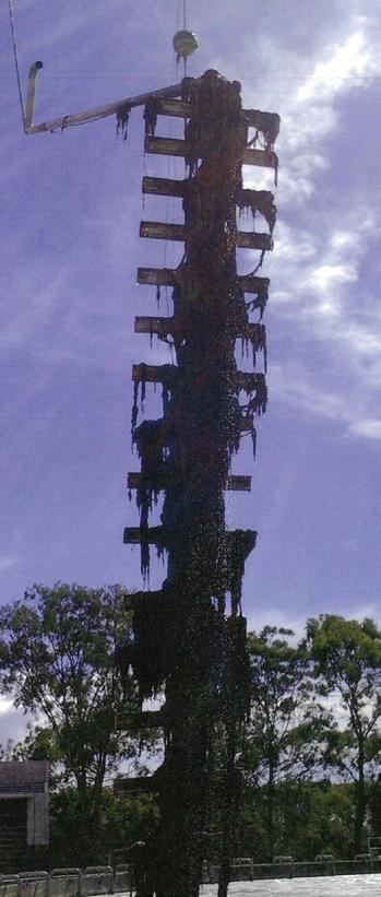
breakdowns. Wastewater settles between pump operating cycles, leading to a build-up of material that has not broken down, such as wipes. These wipes can then get picked up by the pump during its next operating cycle.
To combat wet wipe related issues, Sydney Water is deploying a combination of operational innovations, public awareness campaigns and industry collaboration.
“Traditionally, wet wipe blockages were removed manually and as the problem has increased, Sydney Water has needed to put in place protocols to manage the process.
“At the Cronulla Wastewater Treatment Plant, as an example, step screens now dump the wipes into a water sluice which conveys them to a corkscrew press where liquid is removed and the dry wipes are deposited into a sealed tanker which takes the wet wipes away. 2.5 tonnes of these materials are removed from the Cronulla Plant every week.
“Sydney Water has 679 sewage
pumping stations (SPS). Wet wipes accumulate over time in the well, causing many hazards and maintenance problems. Level sensors and instrumentation become blocked, pumps choked and odour builds up. Traditionally, maintenance crews have gone to SPS’s on a regular basis to manually clean the wet wells. Issues with this process include excessive water usage, high labour costs, confined space entry, pump chokes and ineffective cleaning. This time consuming and labour intensive process is very expensive with each SPS requiring on average five to six manual flushes per year.”
As a result, Sydney Water has introduced an automated process of self-cleaning of wet wells on SPSs. This process also optimises performance of the SPS and has significantly reduced Sydney Water’s operating costs.
“The ‘auto-flushing’ was achieved by modifying the cut out levels of pumps during peak flows for each site via the use of the SCADA system. The concept is that if you started with a clean well you could keep it clean by running the pumps down to a low level near the top of the pump intake so that the pump would skim off the surface material. If done on a daily basis there would be no extra burden on the pumps and there would be no build-up of material, leaving the well clean. This leads to no build-up of material on the measuring instruments and large lumps no longer forming to choke pumps. Without build-up of surface material odour is significantly reduced.
“The direct benefits of having an automated system was a significant reduction in cleaning costs, safety risks removed, corrections of other sewage pumping station faults during implementation, reduction in odour complaints and deferral of major capital outlay for equipment or construction.”
Knowing that an operational response was only part of optimising network performance, Sydney Water developed a multifaceted communications approach to better engage with the community to raise awareness and modify customer behaviour around flushing wipes.
Mr Smith said “Our customer research informed us that packaging claims have a direct influence on individual customer’s choice of wipes and leads to a higher prevalence of flushing these wipes down the toilet.”
Further our research found that:
• Approximately 1 in 3 wipes users flush, which equates to 1 in 4 of the total Sydney population over 15 years of age
• Intimate wipes are the key problem category and packaging claims are influential (more so for women)
• If customers perceive products as biodegradable, they twice as likely to flush them
• Males 15-44 years were the worst flushing offenders
“The survey also found 25 per cent of respondents indicated they would reduce wipes usage after knowing the cost and environmental impact, while 31 per cent would look to switch to another ‘biodegradable’ option.
“With this insight, the ‘Keep wipes out of the Pipes’ program was launched by Sydney Water in May 2015 across multiple communication platforms.
“The strategy was to engage and activate our customer base through creative social media posts that would raise awareness of the issue with a simple call to action,” said Mr Smith.
“The creative concepts, developed by HOST Sydney, aimed to bring a problem which mostly exists underground to the everyday consciousness of our customers. It was about converting an ‘out of sight, out of mind issue’ into one of everyday relevance.
“All materials produced featured a shocking statistic and the call to action to ‘Keep wipes out of the pipes’. These visuals were then able to be easily adapted for use across many channels, from social media, educational programs, right through to the Sydney Water bill.
“Building staff engagement through empowerment was an important element in the communications program. Sydney Water staff were brought along on the program through staff lunchtime sessions and given access to a ‘BBQ pack’ of key messages they are authorised to use with families and friends to build word-of-mouth networks to support the program.
“The media strategy has had a current cumulative reach of over 12 million people across print, online, radio and television. This includes Sydney Water and its spokespeople regularly being cited in the media.
“Our social media reach has exceeded one million people at an average engagement rate of 6 per cent, above the utility industry benchmark of 0.5-2 per cent.
Sydney Water’s education campaign on wipes has produced stunning results. Comparing the Sydney Water Consumer Sentiment Survey conducted for the March Quarter 2016 and those from the April/June Quarters in 2015 found that:
• There has been a 50 per cent
reduction in the proportion of customers who think it’s OK to flush wet wipes
• There has been a 57 per cent reduction in acceptability of flushing baby wipes
• The number of 20-29 year olds (one of the target demographics) who think it’s OK to flush wipes has reduced by 54 per cent
• The number of people 50+ years old who think it’s OK to flush wipes has reduced by 61 per cent
• The number of males of all age groups who think it’s OK to flush wipes has reduced by 46 per cent.
This highly effective campaign also resulted in customer advocates questioning wet wipe packaging claims, including a CHOICE magazine investigation into the packaging claims made by wipes manufacturers, which culminated in a major brand being awarded a ‘Golden Shonky’ at the 2015 Shonky Awards in Sydney. Over 5,000 people have joined CHOICE’s ‘Flushbusters’ campaign to have wipes products more appropriately labelled or removed from sale.
“Market-leading wipes manufacturer Kimberly-Clark has introduced ‘new and improved’ paper rather than plastic based Kleenex Flushable Wipes, along with a commitment to label their non-flushable products with a distinctive ‘do not flush’ symbol.”
“Sydney Water has also closely
supported WSAA’s successful approach to seek approval from Standards Australia to establish a mirror committee to the work of the international committee ISO/TC 224 WG 10 Flushable Products.
“Sydney Water is contributing technical expertise on behalf of the industry in the development of an international standard on ‘flush-ability’, which can be recognised by Australian water utilities as appropriate for local wastewater system characteristics,” said Mr Smith.
Yarra Valley Water (VIC)
Glenn Wilson, General Manager Infrastructure Services with Yarra Valley Water, said the introduction of ‘flushable’ wet wipes and other non-degradable products into Yarra Valley Water’s sewerage network causes significant operational issues.
Materials that do not break down can cause issues in a number of places throughout the network of pipes and pumps:
• Smaller diameter pipes: small numbers of wipes or non-degradable products can cause blockages at bends and fittings, or in the pipe itself (particularly when snagged by tree roots)
• Larger diameter pipes: large numbers of wipes or masses of non-degradable products can cause blockages as they can clump together, or combine with fats to
cause bigger blockages
• Sewage Pumping Stations: material that flows through the network of upstream pipes will accumulate in the wells of pumping stations. These can block the pumps, preventing the station from being able to convey flows and in the worst case, overflowing
• Sewage Treatment Plants: non-degradable products that pass through the inlet screens (these are designed to remove non-degradable materials from the flow stream) can cause damage to mechanical components and interrupt sewage treatment processes.
“Yarra Valley Water has not characterised the non-degradable material we have removed from the sewerage system, so it is not possible estimate what proportion of the material is made up of wet wipes,” said Mr Wilson.
“However, many of our Sewage Pumping Stations must be cleaned out frequently to remove the build-up of non-degradable materials that accumulate in the well. This material includes wet wipes, feminine hygiene products, and other items that have passed through the upstream network of pipes. Currently, Yarra Valley Water is forced to clean one of its larger facilities every three months. Every time, a mass of non-degradable materials between 10 and 20 cubic metres in size is removed from the well.”
If sites are not cleaned out, the build-up of non-degradable material can cause significant operational issues, including:
• Pump blockages, and inability to re-seat pumps once they are put back into the well
• Damage to pumps, and excessive wear on pump impellers
• Fouling of instrumentation and interference with float level switches.
According to Mr Wilson, Yarra Valley Water’s operational teams have noticed an increase in issues caused by non-degradable products in recent years.
“Yarra Valley Water frequently experiences blockages in pumps at Sewage Pumping Stations and Sewage Flow Control Facilities. In these instances, wet wipes and non-degradable materials pass into the well of the site from the upstream sewerage network. They tend to accumulate in the well, and clump together with other wipes and non-degradable material. The pumps at these sites are located at the bottom of the well, so when they start up, they draw the obstruction directly into the pump impeller. If a large enough obstruction remains lodged within the pump impeller preventing it from turning, the pump will stop and the level within the well will rise.
“Yarra Valley Water is alerted to the issue by a remote telemetry system and our maintenance contractor is sent out to correct the problem. We also have multiple pumps at all pumping stations
to provide a level of redundancy. The blockages need to be removed manually, which requires the lid of the well to be opened, the pump to be lifted out by a crane, and the obstruction to be removed by hand. If the well is extremely dirty, and the pumps are blocking frequently as a result, the well must be cleaned out before the pumps are returned. This requires the maintenance contractor to use a vacuum truck to remove the contents of the well. They will often need to isolate flows into the site and enter the well to ensure a thorough clean which is high-risk work.”
Mr Wilson said that Yarra Valley Water had replaced some pumps in its network order to reduce blockages. However, replacing pumps was not a suitable solution for every site.
“In recent years, pump manufacturers have been able to design pumps that are less susceptible to blockages. It is not possible for Yarra Valley Water to employ this technology at every site in its sewerage network due to the extreme cost in replacing all of the older pumps within the network, and also because pump selection must be primarily based around meeting the required duty point (being able to operate across the required flow range and lift the sewage to the discharge point).”
Yarra Valley Water has implemented

a number of measures in response to the growing volume of non-degradable material in its sewerage network. These have included:
• Changing pumps at some sites to types better able to deal with non-degradable material (e.g. chopper pumps, or pumps with impellers that are less susceptible to blockages)
• Installing macerators at inlets to sites
• Increasing the frequency of wet clean outs at sites which accumulate large quantities of non-degradable material.
“The efficacy of these measures has varied, and they have not entirely prevented pump blockages from occurring,” said Mr Wilson.
“For example, while wet wipes and other non-degradable materials may be macerated, the cut up material can reform together in pump wells over time and create an even larger blockage. Therefore, the fixes that involve the use of mechanical equipment have not removed the need for pump wells to be cleaned out.”
In addition, Yarra Valley Water is currently developing an education campaign in regards to the sanitation services it provides.


“It will cover what cannot be flushed down the toilet, as well as how to dispose of an array of items that are regularly flushed, and how the sewerage system works and is maintained,” said Mr Wilson.
The utility also employs targeted community engagement via newspaper and other media following any sewer spills determined to have been caused by large quantities of non-degradable material.
“We are also participating in the development of an international standard for flushable products. Australia’s input to this committee is being coordinated by the Water Services Association of Australia,”said Mr Wilson.
Queensland Urban Utilities (QLD)
Queensland Urban Utilities has also experienced an increase in problems due to wet wipes in recent years.
Queensland Urban Utilities Manager of Trade Waste, Col Hester, said so-called ‘flushable’ wipes contribute to increased maintenance and disposal costs.
“Our treatment plant operators have noticed blockages caused by a build–up of ‘rag’ material on inlet screens have become significantly worse,” he said.
“Call outs to blockages at pump stations and fouled impellers are also on the rise. Not all of the foreign material is ‘flushable’ wipes, but a significant


SEEPEX Smart Conveying Technology extends the life of your stator. Adjustment of the retaining segments takes just 2 minutes and restores 100% pump performance.
Tests have shown up to 3x stator life compared to conventional progressive cavity pump design Join the smart revolution and test our innovation “Smart Conveying Technology”.


SEEPEX Australia Pty. Ltd.
Tel +61.2.4355 4500 pvila@seepex.com
www.seepex.com
proportion usually is.
“It’s estimated we remove around 120 tonnes of wet wipes from our sewerage network every year, which if laid end-to-end, would stretch all the way from Brisbane to New Zealand.”
According to Mr Hester, wet wipes entering QUU’s sewer networks are a growing problem.
“Our operators are definitely reporting the problems associated with ‘flushable’ wipes are getting worse,” he said.
“We’re removing more ‘grit and screenings’ from inlet works at treatment plants and also spending more time maintaining pumps and other equipment.
“We spend about $2.5 million every year responding to more than 2,500 blockages in our network and wet wipes are largely to blame. They often combine with other nasties that people flush down the toilet or sink, such as cooking fats.
Wet wipe accumulations have also necessitated increased pump station maintenance.
“So-called ’flushable’ wipes are made from material that doesn’t break down like toilet paper. They also bind together with other wipes to form what we call ‘flushable ropes’.
“These ropes are damaging for pump stations as they wrap around the impellers, forcing the pumps to work at a harder duty cycle and become very inefficient.
“Responsive maintenance call outs to pump stations have increased considerably.
“Wipes also accumulate on protective screens at pump stations, requiring them to be manually removed and cleaned to allow the pump station to keep operating,” Mr Hester said.
“We’re attending an increased number of unplanned maintenance jobs at pump stations, so we’ve had to place some on higher maintenance frequencies.
“Screens at our sewage treatment plants are also now being cleared of wet wipes more frequently, and increased volumes are being removed for disposal to landfill. We’re currently spending around $600,000 a year removing this rubbish from our plants.
“In some cases the plant inlet screens simply aren’t able to deal with the amount of ‘rag’ coming in, forcing operators to manually remove it. This is very unpleasant and labour intensive work.”
QUU is undertaking a number of other initiatives in response to the wet wipe epidemic.
“We’ve launched a campaign to educate people about what should
and shouldn’t be flushed. This includes billboards, website ads, social media and posters on the back of toilet doors at airports, shops, cinemas and pubs,” said Mr Hester.
“We’re also here to support the consumer watchdog, the Australian Competition and Consumer Commission (ACCC), in its investigation of whether manufacturers’ claims of flushability are deceptive and therefore a breach of consumer law.
“In addition, we’re working with other utilities through the Water Services Association of Australia (WSAA) to develop a standard method for assessing the flushability of products, as well as a way to determine ‘flushable’ wipe mass loads at points within our sewerage system.”
Mr Hester said that ongoing efforts will be required to combat the wet wipe problem.
“The campaign to educate people about the flushability of wipes is still new, so it’s too early to measure any behaviour changes.
“We undoubtedly need to continue with our communications effort to prevent ‘flushable’ wipes from entering the sewerage system.
“If the current trends continue, we may need to invest in redesigned pump impellers that can cope with the accumulation of wet wipes.”
South East Water is another Australian water utility that has had to make operational changes in response to problems caused by wet wipes.
“Last year South East Water took a look at blockages across 50 pump stations and found that 70 per cent were caused by ‘flushable’ wipes,” said Mark McCormack, General Manager for Network Services.
“Together with blockages caused by tree roots and fats and oils, ‘flushable’ wipes contribute towards South East Water’s more than $2.2million per year in sewer network maintenance costs.
“Our data indicates that the number of blockages at our pump stations has increased by around 20 per cent in recent years. Not only are we seeing an increase in pipe blockages caused by ‘flushable’ wipes, but our maintenance regimes are changing at our treatment plants, with more frequent clearing of inlet screens now necessary.
“If not screened out, these materials would cause problems for our treatment apparatus, and potentially impact on the quality of final effluent we could produce.”
Mr McCormack said that South East Water is undertaking media campaigns to raise public awareness of the issue, in addition to participating in industry collaborations aiming to bring about legislative change.
“South East Water regularly runs campaigns via our customer touch points, and also via the media. We are also focused on using the combined weight of our industry through the Water Services Association of Australia (WSAA) to drive legislative change, particularly on labelling and use of the term ‘flushable’. Progress is being made in this area although of course we would like things to move faster.”
“Once customers become aware that these products can cause blockages, not only in our networks but in households too, with messy toilet overflows and expensive repairs, it inevitably results in changed behaviour,” said Mr McCormack.
“We have also recently seen new products come onto the market that are paper-based and therefore break down more easily.”
“That said, we continue to see water companies across the country clearing tons of flushable wipe material from their networks. Only by changing the way these products are marketed and sold will we see significant change, and we’re hopeful that the work WSAA is leading will deliver a good outcome.”
SA Water Senior Manager of Wastewater Operations, Lisa Hannant, said that while SA Water has so far avoided any particularly large fatbergs due to trade waste regulations limiting the greases and fats entering the sewers, wet wipes still pose a problem in the network.
“In the metropolitan area alone, SA Water spends around $400,000 a year combatting gross solids that collect at inlets to treatment plants, of which wet wipes form a large component,” said Ms Hannant.
SA Water field operators have reported increases in floating material in plants and blockages at pumps stations where fat, wet wipes and other material accumulate. This has the potential to cause sewage overflows or backflows into customers’ properties.
“We do get pumps ragged up,” said Ms Hannant. “But we can’t be sure it’s 100 per cent wet wipes.”
SA Water reviews its maintenance programs on an ongoing basis in response to performance data. Ms Hannant said that in one regional plant where rag balls were a recurring
problem, SA Water changed the station’s operation to flush more regularly, delivering smaller rag balls more frequently.
The organisation is undertaking community engagement programs to raise customer awareness of the problems caused by flushing wet wipes, as well as working on a broader industry solution by participating in the international standard development with WSAA.
“We had an info brochure put in SA Water bills last year to raise awareness of the issues caused by wet wipes,” said Ms Hannant.
SA Water has also used Youtube, social media and an in-person education program involving SA Water staff speaking to community groups to engage the public.
“Community education is a key,” said Ms Hannant. “If people are aware of the problems wet wipes cause then that goes a long way to solving the problem.”
According to Theo Vlachos, Wastewater and Stormwater Manager at City West Water, wet wipes have caused an increasing number of blockages for some pumps within the City West Water wastewater network.
“The wet wipes clump together and
cause pumps to block up, especially smaller sized pumps,” he said. “Wet wipes that do not get pumped out gather into large clumps and block pumps and other equipment.”
“Wet wipes are often the cause of blocked pumps, resulting in additional maintenance and repairs, which in turn drives operational costs upwards.”
In some cases, pumps particularly prone to faults have been replaced with pump designs more resistant to clogging.
“We have changed pumps that are better designed to tolerate wet wipes and rags—they don’t get caught as often,” said Mr Vlachos.
“We may need to monitor pumps that are blocking up more often to discover what is the main cause – is it a build-up of wet wipes or other material?”
City West Water has also participated in public awareness campaigns about the blight of wet wipes.
“We joined with the other two metro water companies to provided statements on our website and regular messages on our social media channels. We highlighted CHOICE Magazine giving flushable wipes a ‘Shonky Award’, for example, to show that no wipes should be flushed down the toilet.”
However, Mr Vlachos says there is still work to be done and changing public
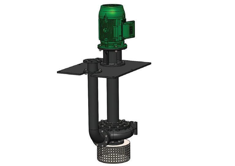
attitudes towards what can be flushed down the toilet is vital.
“We’ve seen a decrease in the problem, but that could be more to do with changing to better designed pumps rather than changes to customer behaviour. We always repeat the message that no wet wipe is flushable – if consumers take this on board we’d have no problems with wet wipes in the sewer system.”
These are just some examples of the ways Australian water utilities are working to defeat the wet wipe scourge and prevent damage to pumps and other infrastructure.
Wet wipes entering wastewater networks is an ongoing problem worldwide, and one that will likely require a combination of measures to solve. Such measures may include pump design improvements and other operational solutions, effective industry collaboration, the development of the international standard for flushable products and continued public engagement.


Recently, I saw an article that used an expressway analogy to compare positive displacement pressure sewer systems to those utilising centrifugal grinder pumps. In this article, the writer compared the centrifugal grinder to an automobile ‘stuck in traffic’, while elevating the positive displacement grinder to ‘super car’ status.
Unfortunately this analogy is a misleading one. It tends to diminish the positive displacement pump’s weaknesses while overstating its relative strengths.
Using this same analogy, let’s take a realistic look at these two very different pressure sewer pump designs.
This comparison can be helpful in explaining the operation of a pressure sewer system, because we are all familiar with the expressway and its function as a main conduit for the flow of traffic from numerous feeder streets. In this way, it can be considered analogous to the primary force main of a pressure sewer system. The force main is also a conduit and serves numerous feeder lines, each powered by one or more grinder pump systems.
In many ways the design of a pressure sewer system is similar to that of an expressway. The force main is intended to accommodate some maximum flow rate based upon the expected inflow from a certain percentage of their many feeder lines during some peak flow period. It may also be designed to accommodate future expansion of the project or subdivision it serves. But, due to the increased piping expense, it is not usually designed to accommodate the maximum flow from all of the feeders at one time. Nor should it be, because such an occurrence is the exception rather than the norm.
On an expressway, the velocity at which one travels is dependent upon its design capacity and the number of vehicles traveling on it at any point in time. If traffic density is within design capacity, the legal speed limit is usually attainable. As the traffic increases it will slow and may even come to a complete halt if the number of vehicles far exceeds its capacity.
Unlike an expressway, however, velocity in a pressure sewer main does not decrease as volume increases. In fact, just the opposite occurs. As more sewage enters the main, velocity increases until it reaches some maximum as defined by a combination of system volume and pressure. If system pressure is self limiting, this maximum volume and velocity can be maintained without adverse effects. If system pressure is not self limiting, pressure will continue to increase due to the pipe friction that results from the volume increase.
An intrinsic feature of the centrifugal grinder pump is that it is self limiting with respect to both flow and pressure. When system flow is low or moderate, as measured by back pressure, the centrifugal grinder will seek a higher flow point on its performance curve. As system volume increases, it will automatically reduce its flow while increasing pressure. In the case of system overload (too many pumps on line at one
time) or system failure (a closed valve or plugged line) the centrifugal grinder will run at what is known as shut off head, and suffer no adverse effects.
During shut off head, pressure reaches some pre-engineered maximum and flow is reduced to nearly zero. The power required to operate the pump at shut off head is about one quarter of that consumed when pumping at normal flow. When system conditions improve, the centrifugal grinder will automatically increase its flow and seek the optimum point on its performance curve even as conditions continue to change.
The centrifugal grinder pump is a lot like an well behaved driver on an expressway. As traffic (sewage volume) increases and backups begin, the driver (centrifugal grinder) slows down and goes with the flow, so to speak. If the traffic comes to a standstill he will stop and idle patiently until he can move forward again. Regardless of the circumstances, he will maintain a pace that is prudent under the prevailing conditions.
The positive displacement grinder, on the other hand, is not self limiting with respect to either flow or pressure. In fact, it is designed specifically to maintain flow at all costs. As long as it is running, it will continue to pump at a steady, unvarying rate. If system volume increases, thereby increasing friction, it will increase its output pressure to whatever value is required to support its steady pumping rate.
In certain applications this could be considered a good feature. But, in the case of a pressure sewer system, damaging over pressure can occur. If too many pumps start at the same time, the friction generated by the sewage flowing in the force main will create extremely high system pressure. Since each positive displacement grinder pump in the system will continue to try to overcome this back-pressure, something in the system must give. Usually the pump motor will overload and trip its thermal switch or circuit breaker. In extreme cases, pipes can rupture or the pump itself can be damaged. Even if the thermal overload keeps this from happening, it is not an acceptable protection scheme since overloading and overheating damages the motor windings and leads to premature failure.
A positive displacement grinder pump can be compared to an expressway driver with a bad case of road rage. As traffic (sewage volume) increases and backups begin, the driver (positive displacement grinder) pours on the gas (pressure) and continues to try to maintain his speed. At some point, though, his luck runs out

and he slams into the slow moving traffic injuring himself or those around him. If only he could idle patiently like the former driver, he could wait out the slow down. But, unfortunately, idling is not an inherent trait of either the road raged driver or the positive displacement grinder.
There is, however, one condition where speed (not pressure) is desirable. Pressure sewer force mains and laterals utilise relatively small diameter pipe and, therefore, depend upon the velocity of the pumpage to keep them clean and free flowing. When only a few stations are actively pumping, flow and velocity can be greatly reduced. The positive displacement grinder contributes to this condition due to its low flow, fixed rate design. The centrifugal grinder, on the other hand, will automatically seek the highest flow it is capable of producing under the conditions, thus increasing fluid velocity and the scouring action it provides.
In fact, one small centrifugal grinder pump will produce the same fluid velocity as five small positive displacement pumps. If we assume a minimum cleansing velocity of 2 feet per second, a single centrifugal grinder will maintain a 2.5” force main. In a positive displacement system, four pumps are required. For a 4” main, the requirement increases to two centrifugals or ten positive displacement units. And, for a 6” force main only five centrifugals compared to twenty-two positive displacement pumps will be required.
What makes the centrifugal grinder pump so flexible is that it is a true centrifugal pump. What makes it so different than other centrifugal sewage pumps is its unique grinder mechanism and impeller design.
The high speed cutter assembly of the centrifugal grinder pump performs over 3200 cutting operations per second. Its product is an extremely fine slurry (not sludge) that is over 96 per cent water. Since this slurry is almost all water, it pumps like water and is therefore able to take advantage of the unique operating characteristics of the centrifugal pump.
Two of these characteristics are extremely important in the design and operation of pressure sewer systems. These are the ability to vary flow and pressure automatically and the reduction of electrical consumption in proportion to reductions in flow.
The centrifugal grinder pump’s unique vortex impeller design allows it to take full advantage of centrifugal action in a high head, low flow environment. Unlike the typical closed vane type impeller, seen on most centrifugal pumps, the vortex impeller resides completely out of the pump volute. A major advantage of this design is that heat producing friction is reduced, substantially, when running at shut off head.
This allows the centrifugal grinder to operated under zero flow conditions for extended periods of time. It is also immune to the damaging radial forces that other impeller designs experience
when running at or near shut off head. Another characteristic of the centrifugal grinder pump is its low maintenance requirements. Since the vortex impeller resides completely outside of the volute, it experiences almost no wear. Its typical life expectancy is therefore that of the pump itself. The close tolerances and running clearances of the positive displacement grinder, on the other hand, demand increased maintenance and promote a shorter life of the pumping components. Also the high speed cutting action of the centrifugal grinder produces far less torque than the slower positive displacement grinder. This lower torque results in increased life of the cutter components.
Although the features and quality of centrifugal grinder pumps varies significantly from manufacturer to manufacturer, one thing remains clear. Their inherent design is far more suitable for pressure sewer systems than other members of the sewage pump family tree.
Joe Evans accidentally entered the pump industry in 1986, and has been trapped there ever since! He is passionate about the sharing of knowledge within the industry. To read more of his insights into the world of pumping, head to www.pumped101.com.
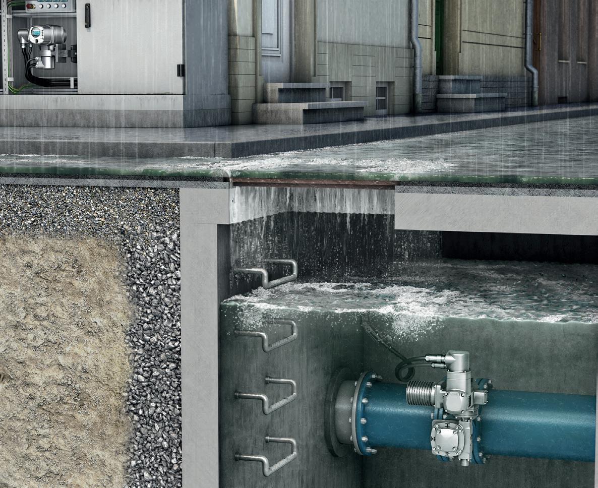
The SA multi-turn actuator for continuous underwater use by AUMA opens up new applications for electric actuators – for water supply, in hydropower plants and underwater valves in general.
A sophisticated sealing system combined with excellent corrosion protection properties qualify AUMA actuators for underwater use. Double sealed cable glands at the electrical connection safely prevent any ingress of water. Inner seals at all housing covers, sometimes coming in pairs, as well as a solid shaft made of stainless steel complete the universal concept.

There has been a persistent misconception that there is a ‘magic bullet,’ in the form of a condition based monitoring (CBM) instrument, that will provide all of the information that you need to evaluate the health of your electric motor system. This misconception is often brought about by the commercial presentations of the manufacturers or sales forces of these CBM instruments. It is the very job of the salesperson to focus on the area of strength for their particular instrument(s) and present it as ‘the only solution you will ever need to solve your every problem’.
In reality, there is no one instrument that will provide you with every piece of information that you need. No ‘Holy Grail’ of CBM and reliability. However, through an understanding of the electric motor system, and the capabilities of CBM technologies, you can have a complete view of your system, its health and have confidence in estimating time to failure in order to make a good recommendation to management.
The purpose of this paper is simple: outline the components of an electric motor system, discuss the modes of failure of each major component, discuss how each of the major technologies address each component, discuss how the technologies can be integrated for a complete view of the system, and discuss the bottomline impact of the multi-technology approach. The types of CBM equipment to be reviewed are standard off-theshelf technologies that are used for periodic testing.
The electric motor system involves far more than just the electric motor. In fact, it is made up of six distinct sections, all with their different failure modes. The sections are:
• The facility power distribution system which includes wiring and transformers.
• The motor control, which may include starters, soft starts, variable frequency drives and other starting systems.
• The electric motor – A three phase induction motor for the purpose of this paper.
• The mechanical coupling, which may be direct, gearbox, belts or
some other coupling method. For the purpose of this paper, we will focus on direct coupling and belts.
• The load refers to the driven equipment such as a fan, pump, compressor or other driven equipment.
• The process, such as waste-water pumping, mixing, aeration, etc.
Most will view individual components of the system when troubleshooting, trending, commissioning or performing some other reliability-based function related to the system. What components are focused on depends upon several factors, which include:
• What is the experience and background of the personnel and managers involved. For instance, you will most often see a strong vibration program when the maintenance staff is primarily mechanical, or an infrared program when the staff is primarily electrical.
• Perceived areas of failure. This can be a serious issue depending upon how the motor system is perceived and will deserve more attention to follow.
• Understanding of the various CBM technologies.
• Training. But since when is training ever not an issue?
The perceived areas of failure provides an especially serious problem when viewing the history of your motor system. Often, when records are produced, the only summary might state something like, “fan failure, repaired,” or “pump failure, repaired”. The end result is that the perceived failure has to do with the pump or fan
component of the motor system.
This especially becomes more of an issue when relying upon memory to provide the answers to the most serious problems to be addressed in a plant, based upon history. For instance, when looking to determine what part of a plant has been causing the most problems, the answer might be, “Waste water pump 1”. The immediate perception is that the pump has a consistent problem and, as a pump is a mechanical system, a mechanical monitoring solution might be selected for trending the pump’s health. If a rootcause had been recorded on each failure, it might have been determined to be the motor winding, bearings, cable, controls, process or a combination of issues.
In a recent meeting, while discussing the selection of CBM equipment, the attendees were asked for modes of failure from their locations. The answers were fans, compressors and pumps. When discussed further, the fans were found to have bearing and motor winding faults being most common, pump seals and motor bearings for pumps, and, seals and motor windings for compressors. When viewed even closer, the winding faults had to do with control and cable problems, improper repairs and power quality. Bearing issues had to do with improper lubrication practices.
In effect, when determining the best way to implement CBM on your electric motor system, you need to take a system, not a component, view. The result is simple: improved reliability, fewer headaches, and an improved bottom line.
Following are some of the more common CBM technologies in use. More detail on the technologies can be found in Motor Circuit Analysis1:
De-energized testing:
• DC High Potential Testing: by applying a voltage of twice the motor rated voltage plus 1,000 volts for AC and an additional 1.7 times that value for DC high potential (usually with a multiplier to reduce the stress on the insulation system), the insulation system between the motor windings and ground (ground-wall insulation) is evaluated. The test is widely considered potentially destructive2
• Surge comparison testing: using pulses of voltage at values calculated the same as high potential testing, the impedance of each phase of a motor are compared graphically. The purpose of the test is to detect shorted turns within the first few turns of each phase. The test is normally performed in manufacturing and rewinding applications as it is best performed without a rotor in the stator. This test is widely considered potentially destructive, and is primarily used as a go/no-go test with no true ability to trend.
• Insulation tester: this test places a DC voltage between the windings and ground. Low current leakage is measured and converted to a measurement of meg, gig or tera-Ohms.
• Polarization Index testing: using an insulation tester, the 10 minute to 1 minute values are viewed and a ratio produced. According to the IEEE 43-2000, insulation values over 5,000 MegOhms need not be evaluated using PI. The test is used to detect severe winding contamination or overheated insulation systems.
• Ohm, Milli-Ohm testing: using an Ohm or Milli-Ohm meter, values are measured and compared between windings of an electric motor. These measurements are normally taken to detect loose connections, broken connections and very late stage winding faults.
• Motor Circuit Analysis (MCA) testing: instruments using values of resistance, impedance,
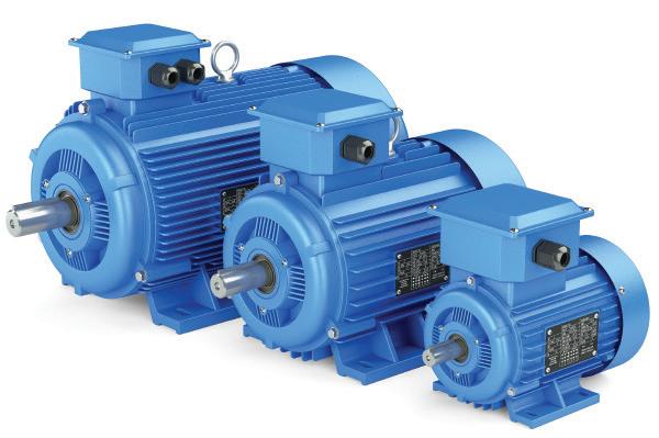
inductance, phase angle, current frequency response, and insulation testing can be used to troubleshoot, commission and evaluate control, connection, cable, stator, rotor, air gap and insulation to ground health. Using a low voltage output, readings are read through a series of bridges and evaluated. Non-destructive and trendable readings often months in advance of electrical failure.
Energized testing:
• Vibration Analysis: mechanical vibration is measured through a transducer providing overall vibration values and FFT analysis. These values provide indicators of mechanical faults and degree of faults, can be trended and will provide information on some electrical and rotor problems that vary based upon the loading of the motor. Minimum load requirements for electric motors to detect faults in the rotor. Requires a working knowledge of the system being tested.
• Infrared analysis provides information on the temperature difference between objects. Faults are detected and trended based upon degree of fault. Excellent for detecting loose connections and other electrical faults with some ability to detect mechanical faults. Readings will vary with load. Requires a working knowledge of the system being tested.
• Ultrasonic instruments measure low and high frequency noise. Will detect a variety of electrical and
mechanical issues towards the late stages of fault. Readings will vary with load. Requires a working knowledge of the system being tested.
• Voltage and current measurements will provide limited information on the condition of the motor system. Readings will vary with load.
• Motor Current Signature Analysis (MCSA) uses the electric motor as a transducer to detect electrical and mechanical faults through a significant portion of the motor system. Usually used as a go/ no go test, MCSA does have some trending capabilities, but will normally only detect winding faults and mechanical problems in their late stages. Sensitive to load variations and readings will vary based upon the load. Requires nameplate information and many systems require the number of rotor bars, stator slots and manual input of operating speed.
Some of the major issues from the various components of the motor system shall be reviewed in order to provide an understanding of the types of faults found and the technologies used to detect them. As an overview, this may not encompass all of the modes of failure that you may experience.
Starting from the incoming power to the load, the first area that would have to be addressed is the incoming power
and distribution system. The first area of issue is power quality then transformers. Power quality issues associated with electric motor systems include:
• Voltage and current harmonics: with voltage limited to 5 per cent THD (Total Harmonic Distortion) and current limited to 3 per cent THD. Current harmonics carry the greatest potential for harm to the electric motor system.
• Over and under voltage conditions: electric motors are designed to operate no more than +/- 10 per cent of the nameplate voltage.
• Voltage unbalance: is the difference between phases. The relationship between voltage and current unbalance varies from a few time to many times current unbalance as related to voltage unbalance based upon motor design (Can be as high as 20 times).
• Power factor: the lower the power factor from unity, the more current the system must use to perform work. Signs of poor power factor also include dimming of lights when heavy equipment starts.
• Overloaded system: based upon the capabilities of the transformer, cabling and motor. Detected with current measurements, normally, as well as heat.
The primary tools used to detect problems with incoming power are power quality meters, MCSA and voltage and current meters. Knowing the condition of your power quality can help identify a great many ‘phantom’ problems.
Transformers are one of the first critical components of the motor system. In general, transformers have fewer issues than other components in the system. However, each transformer usually takes care of multiple systems both in the electric motor as well as other systems.
Common transformer (oil filled or dry-type transformers) problems include:
• Insulation to ground faults.
• Shorted windings.
• Loose connections.
• Electrical vibration/mechanical looseness.
Test equipment used for monitoring the health of transformers (within the selection of instruments within this paper) include:
• MCA for grounds, loose/broken connections and shorts.
• MCSA for power quality and late stage faults.
• Infrared analysis for loose
connections.
• Ultrasonics for looseness and severe faults.
• Insulation testers for insulation to ground faults.
The motor control or disconnect provides some of the primary issues with electric motor systems. The most common for both low and medium voltage systems are:
• Loose connections.
• Bad contacts including pitted, damaged, burned or worn.
• Bad starter coils on the contactor.
• Bad power factor correction capacitors which normally results in a significant current unbalance.
The test methods for evaluating the controls include infrared, ultrasonics, volt/amp meters, ohm meters and visual inspections. MCA, MCSA and infrared provide the most accurate systems for fault detection and trending.
Cables – before and after the controls
Cabling problems are rarely considered and, as a result, provide some of the biggest headaches. Common cable problems include:
• Thermal breakdown due to overloads or age.
• Contamination, which can be even more serious in cables that pass underground through conduit.
• Phase shorts can occur as well as grounds. These can be caused by ‘treeing’ or physical damage.
• Opens due to physical damage or other causes.
• Physical damage is often a problem in combination with other cable problems.
Test and trending is performed with MCA, infrared, insulation testing and MCSA.
Motor supply side summary
On the supply side to the motor, the problems can be broken down as follows:
• Poor power factor – 39 per cent.
• Poor connections – 36 per cent.
• Undersized conductors – 10 per cent.
• Voltage unbalance – 7 per cent.
• Under or over voltage conditions –8 per cent.
The most common equipment that covers these areas include MCA, infrared and MCSA.
Electric motors include mechanical and electrical components. In fact, an
electric motor is a converter of electrical energy to mechanical torque. Primary mechanical problems:
• Bearings – general wear, misapplication, loading or contamination.
• Bad or worn shaft or bearing housings.
• General mechanical unbalance and resonance.
Vibration analysis is the primary method for detection of mechanical problems in electric motors. MCSA will detect late stage mechanical problems as will infrared and ultrasonics. Primary electrical problems:
• Winding shorts between conductors or coils.
• Winding contamination.
• Insulation to ground faults.
• Air gap faults, including eccentric rotors.
• Rotor faults including casting voids and broken rotor bars.
MCA will detect all of the faults early in development. MCSA will detect late stage stator faults and early rotor faults. Vibration will detect late stage faults, insulation to ground will only detect ground faults which make up less than 1 per cent of motor system faults, surge testing will only detect shallow winding shorts and all other testing will only detect late stage faults.
Coupling (direct and belted)
The coupling between the motor and load provides opportunities for problems due to wear and the application.
• Belt or direct drive misalignment
• Belt or insert wear
• Belt tension issues are more common than most think and usually result in bearing failure
• Sheave wear.
The most accurate system for coupling fault detection is vibration analysis. MCSA and infrared analysis will normally detect severe or late stage faults.
The load can have numerous types of faults depending on the type of load. The most common are worn parts, broken components and bearings. Test instruments capable of detecting load problems include MCSA, vibration, infrared analysis and ultrasonics.
There are several common approaches within industry as well
as several new ones. The best use a combination of energized and de-energized testing. It is important to note that energized testing is usually best under constant load conditions and trended in the same operating conditions each time.
One of the most common approaches has been the use of insulation resistance and/or polarisation index. These will only identify insulation to ground faults in both the motor and cable, which represents under one per cent of the overall motor system faults (~ Five per cent of motor faults).
Infrared and vibration are normally used in conjunction with each other with great success. However, they miss a few common problems or will only detect them in the late stages of failure.
Surge testing and high potential testing will only detect some winding faults and insulation to ground faults, with the potential to take the motor out of action should any insulation contamination or weakness exist.
MCA and MCSA support each other and detect virtually all of the problems in the motor system. This accuracy requires MCA systems that use resistance, impedance, phase angle, I/F and insulation to ground and MCSA systems that include voltage and current demodulation.
The newest, and most effective, approach has been vibration, infrared and MCA and/or MCSA. The strength of this approach is that there is a combination of electrical and mechanical disciplines involved in evaluation and troubleshooting. As found in the Motor Diagnostic and Motor Health Study3, 38 per cent of motor system testing involving only study, vibration and/or infrared see a significant return on investment. This number jumped to 100 per cent in systems that used a combination of MCA/MCSA along with vibration and/or infrared.
In one case, a combined application of infrared and vibration saw an ROI of $30, 000. When the company added MCA to their tool box, the ROI increased to $307,000, ten times the original by using a combination of instruments.
There are three common opportunities for electric motor system testing. These include:
• Commissioning components or the complete system as it is newly installed or repaired. This can provide a very immediate payback for the technologies involved and will help you avoid infant mortality disasters.
• Troubleshooting the system through the application of multiple technologies will assist you in identifying problems much more rapidly and with greater confidence.
• Trending of test results for system reliability, again using the proper application of multiple technologies. Using tests such as MCA, vibration and infrared, potential faults can be trended over the long term, detecting many faults months in advance.
This paper provided a brief overview of how multiple technologies work together to provide a good view of the electric motor system. Through an understanding and application of this approach, you will realize fantastic returns on your maintenance program.
1 Motor circuit analysis: theory, application and energy analysis, Howard W. Penrose, Ph.D., SBD Publishing, ISBN: 0-9712450-0-2, 2002.
2 Potentially destructive: any instrument that can potentially change the operating condition of the equipment through mis-application or finish off weakened insulation conditions shall be considered potentially destructive.
3 Motor diagnostic and motor health study, Penrose and O’Hanlon, SBD Publishing, 2003.










In many cases, a variable speed drive (VSD) can provide real benefits to a pumping system in regards to energy efficiency, reliability and system control. However, to get the greatest benefit, the right VSD must be matched to the system and application. Here, we look at some of the important considerations to factor into your choice of VSD.
The energy consumed by pumps makes up a significant proportion of a pumping system’s lifecycle costs. In applications with variable flow or pressure requirements where a single pump is used, that pump will be sized for the maximum duty requirements. Therefore, whenever it is operating at demands other than the maximum, it will be using more energy than is actually required and therefore will be operating inefficiently.
In such instances, employing a control method to reduce the power used by the pump at times of reduced demand, such as a variable speed drive, can result in significant energy and cost savings.
Effectively, the VSD changes the pump curve to match changes to the system curve and ensure that the pump operates within its ideal range.
Additional benefits to a system realised through VSDs may include improved control over a system, meaning that variations in process conditions can be corrected rapidly, preventing flow or pressure surges.
Preventing a pump from operating at speeds above those necessary for the application and eliminating the need to throttle can also reduce unnecessary wear on pump components like bearings and seals, increasing their operating life and improving system reliability.
When designing new pumping systems, installing a VSD can often eliminate the need for bypass lines and control valves, which helps offset the cost of the VSD.
The most commonly used VSDs in pumping applications are variable frequency drives (VFD), which control an electric pump motor by varying the frequency and voltage supplied. This type of VSD is particularly popular due to affordability and cost-effectiveness, and is particularly useful in systems with high friction losses.
However, other VSD technologies include hydrostatic drives, fluid couplings, DC drives, continuously variable transmissions, eddy current drives and slip ring motors.
Is a VSD right for your system?
Before going into the details of VSD

selection, you must first be sure that a VSD really is the most economic and effective solution for your pumping system.
While VSDs often provide considerable advantages for pumping systems with variable duty requirements, they are not invariably the most economical solution to oversized pumps. In some cases where the duty requirements don’t vary, resizing the pump, changing the impeller diameter, or even replacing the pump with a correctly sized pump may result in greater lifetime cost savings at a lower initial cost than fitting a VSD.
Additionally, VSDs are not without their potential downsides if applied inappropriately and these must be taken into consideration. Most of these can be readily be avoided or resolved if taken into account when selecting equipment.
It is important to consider:
• The VSDs own internal losses – if appropriately applied these should be insignificant compared to the energy savings generated.
• The type of motor in the system – when retrofitting a VSD to an

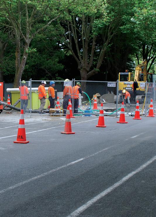

A WHISPER QUIET RANGE OF PUMPS DESIGNED FOR NOISE SENSITIVE APPLICATIONS.
The new range of Sykes Quiet Solution (QSM) pumps have been designed to comply with the noise output regulations governing work sites and urban areas.
The QSM has a noise level output of 67 dBA at 7m and features impact resistant polyethylene panels, roof, vents and doors.
The Steel bunded chassis features a single point lift eye, fork tynes and houses the 345 litre polyethylene fuel tank.
For more information on the full range of Sykes pumps visit us at www.allightsykes.com or freecall 1300 255 444 to speak with one of our sales and project efficiency experts
existing system, it is important to ensure that the motor is VSD compatible and will not overheat at low speeds due to insufficient cooling. The VSD must also be correctly sized to the motor.
• Potential vibration due to resonance conditions – variable frequencies can increase the likelihood of encountering a resonance that causes vibration problems. This can usually be avoided by calculating hydraulic resonance and structural resonance and/or conducting analyses such as passing frequency analysis or modal testing.
• Rotor dynamics – varying speed can increase the likelihood of a rotating element reaching a lateral critical speed, which can cause vibration.
• Pulse width modulation switching – it is possible for the voltage waveforms of a VSD to cause electromagnetic interference that may affect other equipment. Filters and screened cables between the VSD and motor can combat this.
All in all, VSDs should not be used as a
‘magic fix’ for a poorly designed system and a proper cost-benefit analysis should always be conducted to ensure that investing in a VSD is justified.
In order to appropriately and effectively apply a VSD, the requirements of the pumping system in question must be well understood.
The key consideration when considering installing a VSD is the pumping application itself.
In order to reach the desired flow rate, the pressure in the pumping system must overcome the losses caused by static head (the elevation differential) and friction head (the losses caused by the friction between the liquid being pumped and the internal surfaces of the system).
The comparative values of static and friction head in a pumping system can impact the benefits achieved by a VSD.
VSDs are often an ideal control method in systems employing rotodynamic pumps where friction loss dominates (such as a closed loop system or a long pipeline). This is
Our continuous exposure to a wide range of problems and Industrial applications across numerous markets, has ensured we have the know how to handle pump repairs of all sizes and complexities, including re-engineering, testing, laser alignment and condition monitoring.
With each repair job we implement a thorough inspection process and follow strong control and stringent acceptance criteria carried out by a team dedicated to keeping your pump working at optimal performance.
Hire
Link Pumps has been servicing the needs of Australian Industry with pump hire solutions for over 50 years, and as such has built a reputation for being able to solve complex engineering problems and additionally undertake complex setups with complete reliability notwithstanding working to the exacting standards of environmental and occupational health and safety expected by that of our customers and regulatory authorities.
because the ratio of flow versus speed will be very linear and there will be a significant reduction in energy use as a result of reduction in speed.
However, in systems with high levels of static head, VSD control can be more difficult because the reduction in flow is not necessarily proportional to speed and a small speed reduction can result in a much greater reduction in flow and efficiency. In this kind of system, care must be taken to plot pump curves at various speeds against the system curve, and to calculate the percentage flow change against the speed change and plot it against flow to determine if the sensitivity to speed change is to high at low flow rates.
In systems employing positive displacement pumps, flow is proportional to speed, however pressure may not be. This can reduce the energy savings achieved when using a VSD to reduce speed. This must be taken into account when evaluating the benefits of a VSD. As always, the speed range over which the pump must operate should also be viewed with regards to its effects on other components of the system such as lubrication, cooling and valve
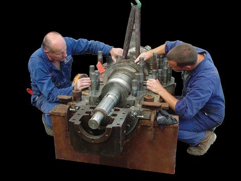
For all your Pump Hire and Repair needs you can’t go past Link Pumps, so call us now…. We perform, Anytime, Anywhere
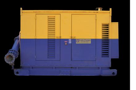
operation, as well as the characteristics of the fluid being pumped, such as solids accumulation, liquid temperature and viscosity—especially if the speed range is particularly wide.
The benefits of the VSD over time must be weighed against the initial costs of the unit. These may not be restricted to the cost of the unit itself, especially when retrofitting a VSD to an existing system. Existing components (such as drivers, motors and couplings) will need to be evaluated for their suitability for working at variable frequencies. In some cases they may need to be replaced.
A life cycle cost analysis should be conducted for control alternatives, taking into account the initial cost of the unit, costs of installation and commissioning, operation costs, maintenance costs, repair costs, energy costs, decommissioning costs and any other relevant costs to be incurred over the system’s life cycle.
The control philosophy by which the VSD will operate is also an important consideration. Often VSDs use
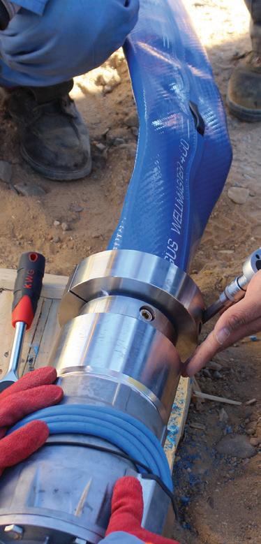
programmable logic controllers to achieve a specific objective in response to signals from condition monitoring devices.
These may include:
• Maintaining a constant pressure – signals from a pressure sensor to maintain a set system delivery pressure regardless of system flow demand.
• Maintaining a constant level – a level sensor allows the VSD to maintain a set level in a tank or sump regardless of flow variance.
• Maintaining a constant flow – a flow meter sends signals to the VSD to alter pump speed to maintain a set system flow.
Maintaining a set temperature – a temperature sensor is used to allow the VSD to maintain a set temperature by varying flow.
Among the most important additional considerations when choosing a control method for a pumping system are the user interface, the environmental conditions the equipment will be
exposed to and any relevant implications to safety.
The complexity and variety of inputs required and the different parameters of experience of operators may mean that a simpler or more expansive user interface will suit your application. The environmental conditions in the area where the VSD will be housed are also important to consider and can have implications on how it is enclosed and the safety of operation and maintenance activities. The VSD should comply with all relevant safety and environmental standards. Some VSDs also have additional safety functionalities that may be relevant to your application. As with any equipment, the quality of the brand, warranty and after sale support are also important factors in purchasing decisions.
In a wide range of applications, a wellselected and appropriately deployed VSD can provide substantial benefits to your pumping system. However, VSDs are not a ‘one size fits all’ solution and it is important to do the research first to determine the specific requirements of your application.

Wellmaster is the Industry Standard Flexible Rising Main for all types of ground water extraction and well-monitoring operations.

OVER 90,000 installations worldwide
Flexible Rising Main

Wellmaster Approvals:
Reg 31 UK
NSF 61 USA/Canada
DVGW W270 Germany
DM174 I taly
Institut d’Hygiene Switzerland
AFNOR France
AS 4020 Australia/NZ

Year after year, compressors are developed to handle higher speeds and capacities. At the same time, they can also handle gases at higher pressures and densities, so that the power input is ever increasing and designed into a smaller and higher speed package.

The hydraulic considerations needed to be taken into account when selecting the correct pump include: system

design, flow rate, system resistance and duty point.
Shock, vibration, energy dissipation and bearing loading should be kept at a minimum for the pump to have a long, problem-free operating life.
Of course, compromises exist due to economic factors; after all, there isn’t an ideal pump for every application.
Hence, the pressure on coupling manufacturers has also increased in order to provide a solution to transmit power from the driver to the pump/ compressor.
All this has to be done whilst compensating for a finite amount of misalignment; angular, radial and axial.
The household duty of the coupling does not stop there. Very often with applications involving motor and gear drives, there are high frequency torsional impulses produced by the driver. It is the job of the coupling to prevent the transmission of these torsional impulses to the compressor as the impellers are already highly stressed.
Along with any pump/compressor
system, the coupling should also have a long life with low maintenance requirements.
Since a coupling has some mass, it tends to lower the critical speed of the overall system. Therefore, it should be designed in such a way as to lower the critical speed by the lowest possible amount. It should be lightweight and of course, low in cost.
Windage and noise are two other factors that need to be accounted for. Older coupling designs produce windage and noise which often causes a nuisance because it sucks the oil from the bearings adjacent to it.
Coupling designs must combine maximum stiffness with the highest possible flexibility to make them ideal for fast-running drives whether it be gas and steam turbines, high speed pump drives, turbo compressors, boiler speed pumps and generators.
Whatever the application, Deanquip are your partners for high speed couplings.
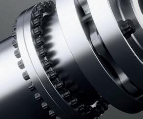


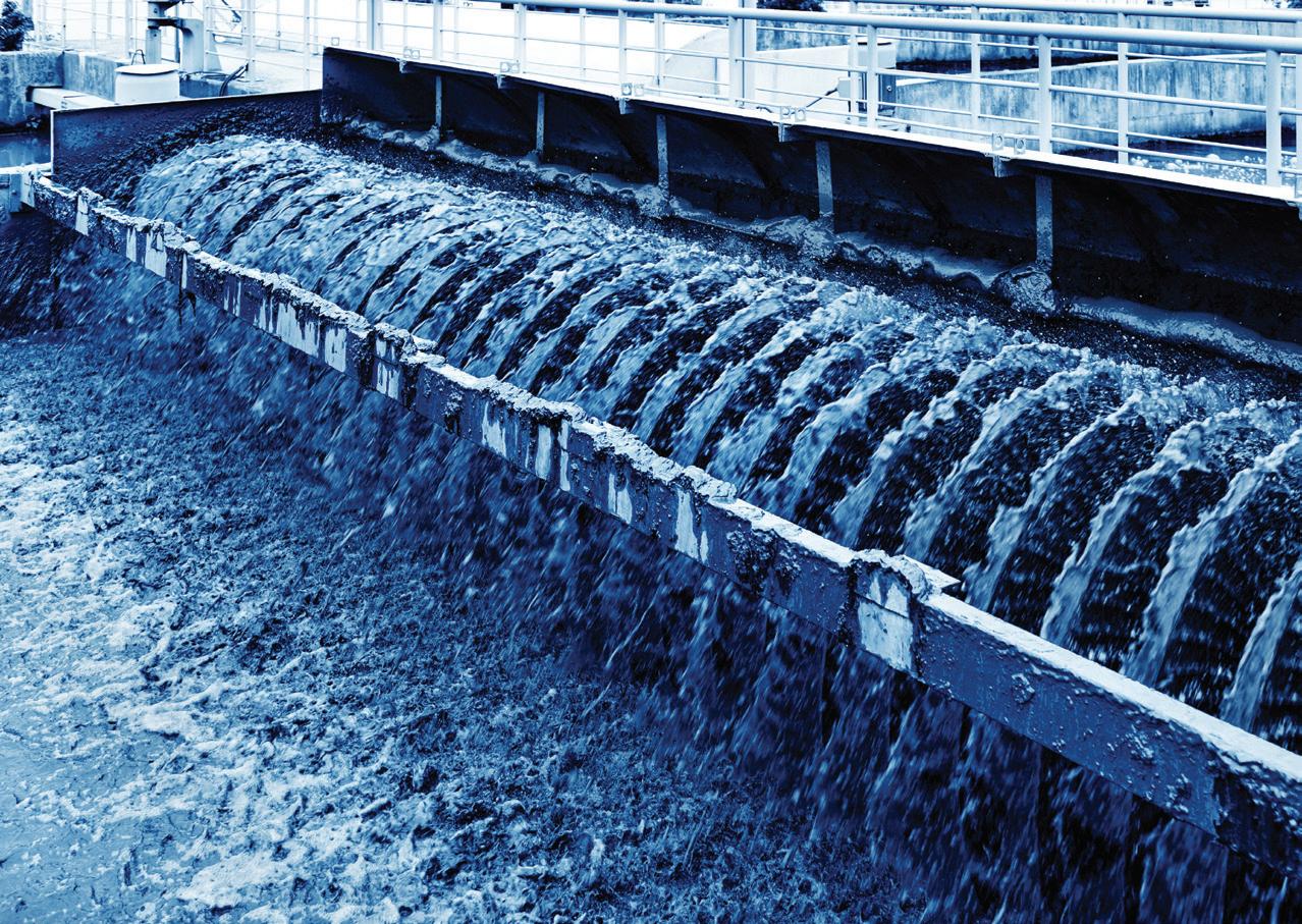
With a key focus on awarded tenders, industry news, project summaries as well as policies and regulations that are shaping the industry. This is an indispensable guide to what is really happening in the Australian water industry.

know who was awarded tenders
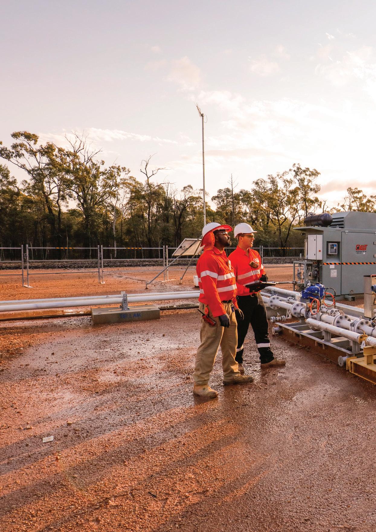
As the mega CSG-LNG projects in Queensland shift into their operational phases, Queensland Gas Company (QGC) is continuing the hunt for reserves, expanding its natural gas tenements in Queensland through Project Charlie.
With Australia’s LNG industry emerging from its construction boom, QGC’s new development, Project Charlie, aims to support Australia’s gas production through a $1.7 billion investment in infrastructure and wells, which will create up to 1,600 industry jobs.
Project Charlie is a two-year gas development project by QGC and its joint venture partners China National Offshore Oil Corporation and Tokyo Gas.
Gas developed from Project Charlie will be available to either meet domestic gas supply commitments, or production needs at the QCLNG Plant on Curtis Island.
Development will involve construction of the following:
• Installing a 240 million standard cubic feet of gas per day (mmscfd) Field Compression Station (FCS)
• Installing one 35km 900mm diameter HDPE water trunk line
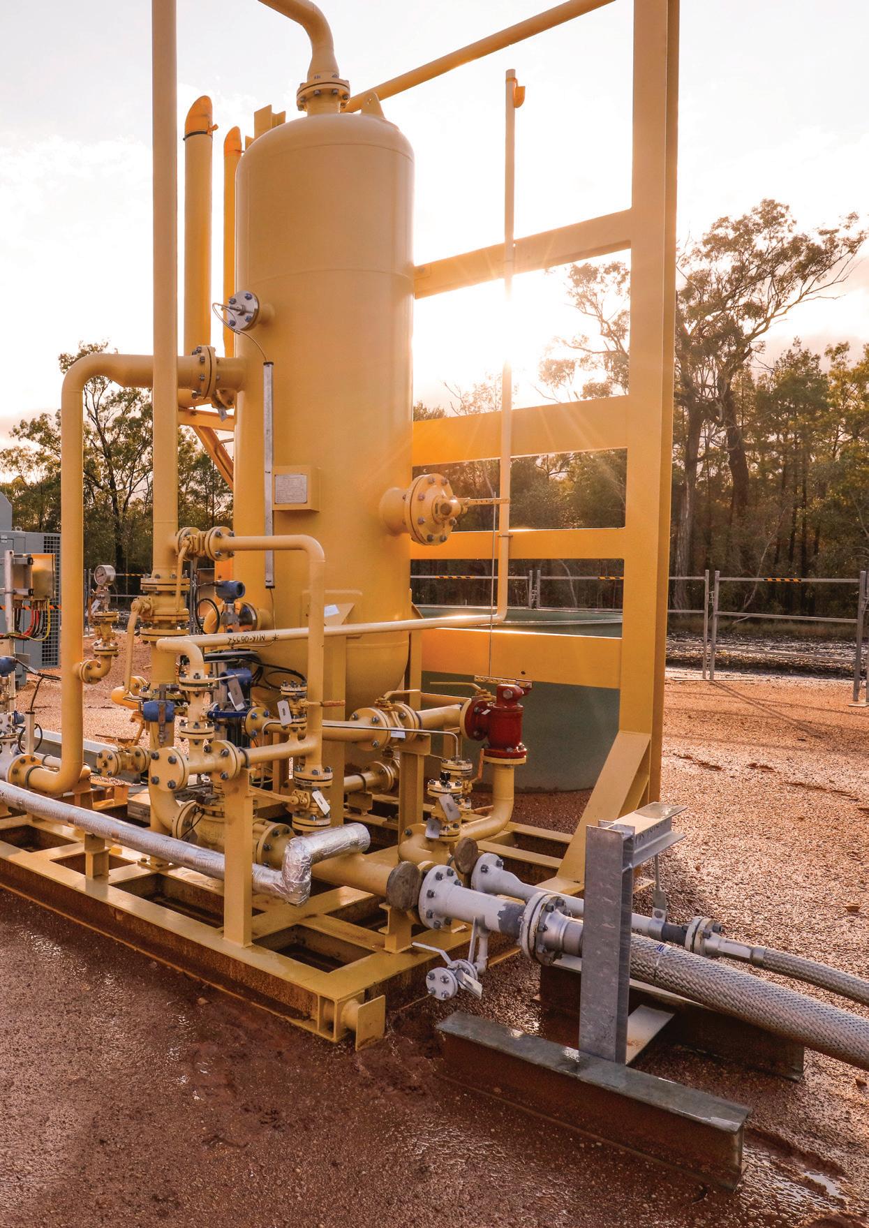
• Installing one 35km 900mm diameter CSG trunk line
• Installing two ponds
• Installing two pump stations
• Installing an automation package
• Installing power infrastructure (a 132kV overhead transmission line, a 132/33kV substation and 33kV distribution building, as well as brownfields upgrades)
• Installing general infrastructure such as access roads and accommodation
• Installing temporary infrastructure such as communications and offices
• Some minor procurement and logistics management.
Once constructed, the new infrastructure will feed into the existing gas processing facilities at Woleebee Creek, just south of where the Charlie Field Compressor Station will be established.
These works are part of a continuous investment by QGC in its Surat Basin gas assets, which supplies gas to domestic markets as well as the Queensland Curtis LNG (QCLNG) facility on Curtis Island, which exports to international markets.
Project Charlie aims to ensure a continuous gas supply to QCLNG for export as well as QGC’s domestic gas customers.
QGC Managing Director Tony Nunan said “Project Charlie builds on the back of all the infrastructure we’ve put in place in phase one of the QCLNG development, and allows us to step out with our next lot of wells and a compressor field station.”
QGC and its parent company, BG Group, appointed CPB Contractors (formerly Leighton Contractors) as the main contractor for the project, and they began construction in late 2015 after the project received environmental approvals from the Federal and Queensland governments.
The development of the new wells, pipelines and compressor station will not only support QCLNG, but the investment will also create over a thousand jobs over the two-year construction phase, as well as ongoing operating and maintenance work once construction is complete.
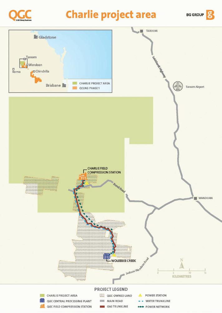
Mr Nunan said the development will help sustain Australia’s natural gas supply and support the gas and resource industry with new opportunities.
“The Charlie development will help to sustain the benefits of our investment in local communities and the state, including up to 1,600 construction jobs and business opportunities during the two-year project,” Mr Nunan said.
“This is a vote of confidence in the secure, long-term future of Queensland’s natural gas industry, which will employ Queenslanders for many years to come.”
Local suppliers within the Queensland gas industry are also likely to benefit from the new project, including specialist engineering, design and fabrication business, Red Industrial,
which currently delivers components to QGC assets in the region.
Project Charlie was named after the section of the block on which the largest part of the development will take place. This location and the area where the compressor station will be built, was chosen due to its land topography and its proximity to the existing and proposed infrastructure.
Once built, the Charlie Field Compressor Station (FCS) will compress gas supplied from the natural gas wells before being transported down a pipeline to the Woleebee Creek Central Processing Plant, to be further compressed.
The gas will then be transferred
along QGC’s gas collection header to the export pipeline, which connects to the QCLNG Facility. This compressor station is anticipated to have a project lifespan of 30 years, including the construction period.
A critical element of any CSG project is managing the water that is generated through the gas extraction process.
The water pipeline being built as part of the project will transfer water from the Charlie regional storage pond with a tie in to the Phillip Intermediate Storage Pond, and then onto the Woleebee Creek aggregation pond adjacent to the Woleebee Creek Water Treatment Plant, where one or more existing ponds are used to balance associated water flows.
The new pump station being built will pump water to the Woleebee Creek clarified raw water pond prior to treatment at the Woleebee Creek WTP.
QCLNG was the world’s first LNG project to use coal seam gas and it joined the export ranks, with its first
production in December 2014. Since then, the plant’s first train has exported 62 cargos of LNG to overseas markets.
Commercial operations from its second train began in November 2015, after QGC assumed control of train 2 from Bechtel Australia, which originally built the facility.
QGC now has full control of both LNG trains at QCLNG and is investing in developments such as Project Charlie, to help sustain gas production and supply to the plant.
QGC operations involve the production of natural gas in more than 2,000 wells within the Surat Basin and Southern Queensland. The gas produced is transported via a 540km pipeline to the Curtis plant for conversion to liquefied natural gas (LNG) and export to overseas markets. The Curtis LNG facility involved more than four years of development and construction work before it was operational.
By mid-2016, both trains at QCLNG are expected to reach a plateau in production, meaning they will be producing enough LNG for
approximately ten vessels per month, or the equivalent of exporting around eight million tonnes of LNG per year.
The QCLNG project is one of QGC’s major developments, and investment in more wells and advanced gas infrastructure aim to sustain the plants gas supply. Investment in more gas production facilities will also have an impact on domestic supply, as QGC supply gas to local markets for power generation.
Project Charlie’s two-year construction phase is predicted to provide a local boom for the industry in the Western Downs region and the development highlights that there is still current investment in Australian gas production and opportunities to support gas production for the future.
CPB Contractors began construction on Project Charlie in late 2015, and the development is expected to be completed in 2017.
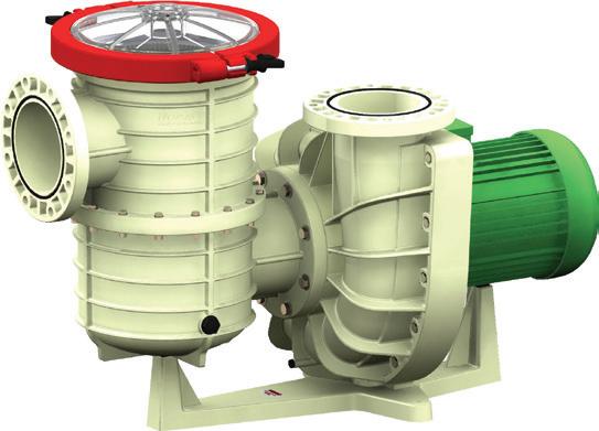
K-One Fluid Power supply hydraulic pumps, motors, filters and valves for mobile and industrial applications, and design bespoke hydraulic power units (HPUs) and components. K-One is the official distributor in Australia and New Zealand for Kawasaki, AMCA, TDZ and Argo Hytos and has supplied over 4,000 K3VL axial piston pumps to a Queensland coal seam gas industry manufacturer in the past eight years.
Kawasaki K3VL Piston Pumps, in combination with K3X Piston Motors, have been the preferred option for CSG HPUs and drive heads. As the HPUs are located in rural Australia, where the gas fields are isolated and hard to reach, it is difficult to respond quickly to emergency breakdowns. Regular servicing or repairs are not feasible, so pumps need to deliver consistent high performance without the need for frequent servicing. Kawasaki K3VL
pumps are specified with a higher flow rate and lower noise production than many competitor products.
In terms of quality and reliability, the K3VL pump and the K3X motor perform to the most exacting expectations. Operating 24/7 in remote arduous environments for over five years and 40,000 hours, the installations have not missed a beat. K-One is currently planning a proactive campaign to service these pumps with replacement or conditioned parts to ensure they will last another 40,000 hours in continuous service. This reconditioning to “as new” condition will be achieved at a significantly lower cost than replacing the pumps with brand new products.
More recently K-One have designed and introduced a direct mounted proportional control valve, along with an artificial load and bypass manifold. This was done with the cooperation of K-One’s proportional valve manufacturer
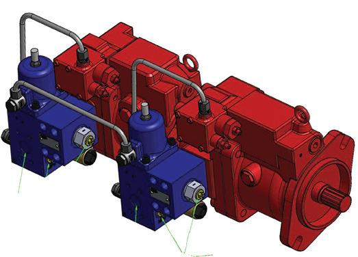

AMCA in the Netherlands, providing a packaged solution to the benefit both the manufacturer and the end user. K-One has improved on the original system design by reducing the number of in-line valves, reducing pressure drop through the pump-mounted proportional flow control valves and saving on overall running costs by as much as 25 per cent. The artificial load and bypass manifolds required also reduce the number of hoses and fittings, reducing leakage points and improving production procedures.
Other industries are not forgotten with the K3VL Pump as K-One provide tailor-made solutions utilising AMCA Proportional Control Valves and Argo Hytos Filters and monitoring equipment.
K-One are very excited about the future with new products coming on-line and look forward to working within both proven and the developing Australian industries.



Four dedicated professionals, together with a combined 65 years of pumping experience, founded Pioneer Pump Inc USA in 1998 to design and manufacture the most reliable and efficient pumps. They also developed a worldwide packaging and distribution infrastructure and network.
Located in Victoria, Pioneer Pump’s Australian facility is the central hub for supply into Southeast Asia and the pacific region. A 2,000m² factory/ warehouse provides an overall facility which houses a large inventory of pumps and spare parts carrying close to the full product range.
Our Australian team is comprised of lively and innovative individuals with strong prowess who are dedicated to fulfilling the vision we share. With over 140 years of experience in our selected fields there is no room for error or mistake when it comes to serving our customers.
The representative sales team for Pioneer Pump, led by Australian founder Steve Bosnar, have the communication skills and, along with their knowledge of our products, they have the capability to answer all questions and queries.
Our Australian site is home to engineers that have been expertly
trained to meet deadlines, restrictions and changes due to individual customer needs throughout the assembly line to ensure the product is quintessential and delivered on time.
Over the past 18 years, we have built up a portfolio of world class pumps that tend to various industries across the globe and a global company that exceeds all expectations.
For more information, please call (03) 9988 1650 or visit
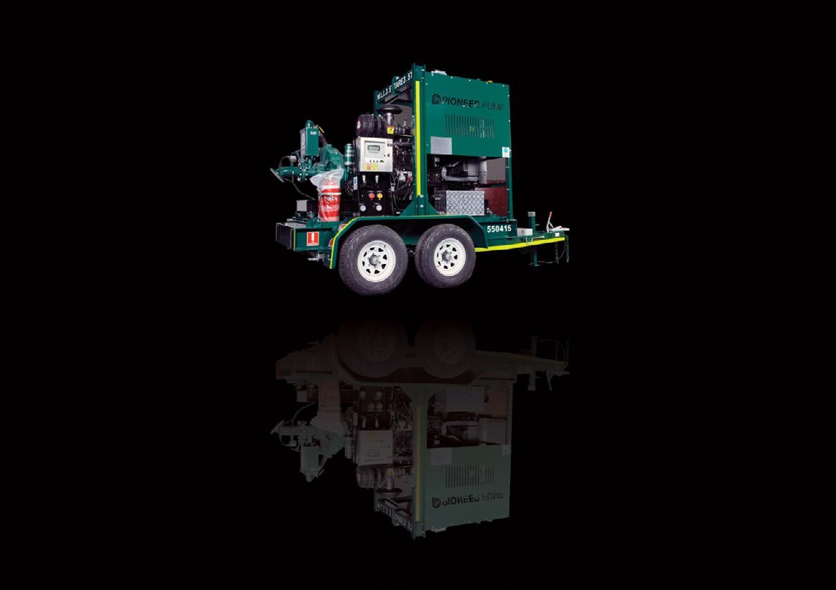


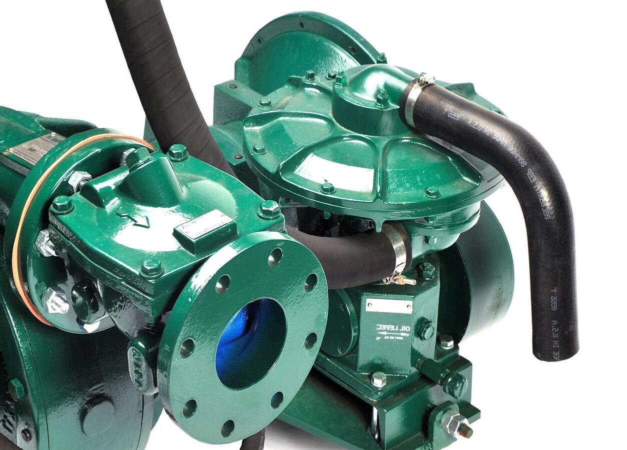

Australia’s next generation of submarines will be built at the Adelaide shipyard, in a partnership between the Federal Government and French naval shipbuilding company DCNS. The Future Submarines will be powered by pump jet propulsion, providing them with a tactical advantage over other similar submarines.

Identified in the 2009 Defence White Paper, the Federal Government’s Future Submarine program was established to deliver an affordable, regionally dominant, conventional submarine capability to Australia, sustainable into the foreseeable future.
Submarines are the most complex, sensitive and expensive Defence capability acquisition a government can make. They are of strategic importance to Australia, and a critical element in our maritime security planning, with our national security and economy dependent on secure sea lanes.
The Future Submarine program represents an investment in the order of $50 billion in Australia’s security, and will be defined by a capability design, construction and sustainment challenge of unprecedented scale and complexity, spanning decades.
Australia’s location and geographic characteristics mean that there are no off-the-shelf submarine options that
meet our unique submarine capability requirements. As a consequence, in February 2015 the Federal Government commenced a competitive evaluation process to select an international partner to design and build the next generation of submarines.
Three groups were invited to participate in a Competitive Evaluation Process (CEP) to select the manufacturer of the Future Submarines: DCNS of France, TKMS of Germany and the Government of Japan.
In April 2016, it was announced that DCNS had been selected as the preferred international partner for the design of the 12 Future Submarines.
This rigorous and independent CEP was led by the Head of the Future Submarine Program, Rear Admiral Greg Sammut AM CSC, and General Manager Submarines, Rear Admiral
Stephen Johnson USN (retired), who was previously in charge of the program to replace the Ohio Class ballistic missile submarines.
The process was overseen by an independent Expert Advisory Panel, chaired by former Secretary of the United States Navy, Professor Donald Winter. It was peer reviewed by Vice Admiral Paul Sullivan USN (retired) and Rear Admiral Thomas Eccles USN (retired).
The decision to work with DCNS was driven by their ability to best meet all of Australia’s unique capability requirements. These included superior sensor performance and stealth characteristics, as well as range and endurance similar to the existing Collins Class submarines. The Government’s considerations also included cost, schedule, program execution, throughlife support and Australian industry involvement.
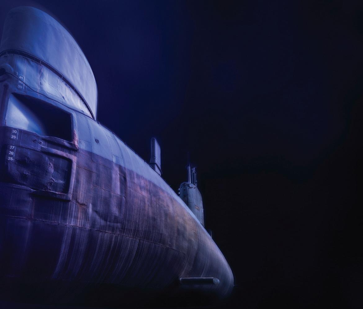
DCNS will provide Australia with a derivative of its Shortfin Barracuda class of submarine. The Barracuda class submarines have an extremely long range and endurance capability; superior sensor performance (particularly in the sonar suite); state-of-the-art stealth technology; and habitability for extended periods at sea, across both open oceans, and in high intensity operational scenarios. The Shortfin Barracuda is 97m in length and displaces 4,500 tonnes of water when it surfaces.
The Shortfin Barracuda is powered by pump jet propulsion, which means it can move more quietly than submarines with obsolete propeller technology. In a confrontation between two otherwise identical submarines, the one with pump jet propulsion always has the tactical advantage. Australia’s Future Submarines will use a pump-jet
propulsor that combines a rotor and stator within a duct, to significantly reduce the level of radiated noise and avoids cavitation. This technology replaces obsolete propeller technology used in older submarines.
The sonar suite performance will be the best available ever for a submarine this size. It is this coupling of excellent acoustic discretion, leading edge detection capabilities and pathways for technology development that will keep Australia ahead of any regional adversary now and in the future.
According to DCNS, “The Shortfin Barracuda Block 1A, designed by DCNS specifically for the Royal Australian Navy, will be the recipient of France’s most sensitive and protected submarine technology and will be the most lethal conventional submarine ever contemplated.
“The Shortfin Barracuda is a magnificent, inspiring submarine which will remain technologically superior until well into the 2060s.”
A requirement of the CEP was that the submarines be built in Adelaide, creating a sustainable Australian naval shipbuilding industry and provide the certainty that industry requires to invest in innovation and technology and grow its workforce.
DCNS has committed to building a new mega submarine construction facility in Adelaide which will rival any other in the world.
The $50 billion investment in the Future Submarines will directly sustain around 1,100 Australian jobs and a further 1,700 Australian jobs through the supply chain.

My pump career began in February 1974 when I joined the Thompsons Byron Jackson Division of Borg-Warner. Prior to this, I got a degree in Metallurgy while I was a trainee at the BHP steelworks in Newcastle. I then went overseas for eight years, spending two years in London and the last six in Montreal, Canada.
While in Canada I studied at McGill University, graduating with an MBA, and I met my wife and had two children before coming back to Australia. On my return, I approached a number of companies involved in manufacturing heavy engineered products, with Thompsons Byron Jackson offering me a career path to managerial levels. At this point I’d only worked in the steel industry so when I started I didn’t know which end of a pump sucked and which blew.
I was recruited, in part, because of my MBA but there was still a huge learning curve when I started in the industry. I spent two years in the sales division in Melbourne before moving to Castlemaine, and even though I didn’t know much about pumps, Thompsons had a very good application and engineering section who provided me with good technical support. I found pumps to be an interesting business, and liked the processes, products and skilled people.
The most memorable moment in my career would have to be getting the boss’s job. Right from the start, there was the view that I would eventually become general manager, as long as I didn’t stuff up. I always wanted the job and when it was finally handed to me it was the culmination of my career plan.
Bill O’Hehir was the general manager at Castlemaine before me and he guided me in many ways with a lot of down-toearth, homespun advice. He had great knowledge of people, business and management and was my mentor from

1983 until his retirement in 1990.
The greatest piece of advice he gave me was to understand the politics and learn to manage upwards. He also told me to not surround yourself with idiots and hire good people that will make your job easier. I took his advice and had some very talented and intelligent guys in my management team.
I spent my 32 year career working at Thompsons with 16 of those years as the general manager, before retiring in 2006, when I was 65.
I worked with many other interesting pump personalities over the years including Allan Jackson, who was the managing director of BTR Nylex, when Thompsons Kelly and Lewis was taken over by BTR Nylex in 1987. Under his leadership, Thompsons Kelly and Lewis was awarded privileges given to no other business unit in the BTR Nylex stable.
Other than Allan, Jim Quain at Flowserve and Les Boelckey at United were also good friends and advisers. My accountant, George Milford, was particularly skilled not just as an accountant but as a manager who understood the business, and sales manager Antony Grage was a very intelligent man.
Bob Moore was also an interesting character. He was no longer working when I knew him but he had previously worked with Bill O’Hehir and was close with Allan Jackson. Bob was the head of Kelly and Lewis for a while and Alan was the head of a company that owned Thompsons Kelly and Lewis, so there was a bit of a Kelly and Lewis mafia in play.
I’m a life member of Pump Industry Australia and I go to their dinner once a year, and I also have lunch with my old colleagues about once a month.
Times have changed
The biggest changes that have occurred in the pump industry are the rationalisation of business and the reduction in local manufacturing.
For example, Flowserve is the successor to Thompsons, Kelly and Lewis, Worthington, Ingersoll-Rand, and Giles & Gaskin. When I joined, we had 600 people, and Kelly and Lewis would have had the same number at Springvale. Before me, Kelly and Lewis took over Worthington, then we took over Ingersoll Rand, merging four major Australian players, and becoming Thompsons Kelly and Lewis. When I began, we would have had about 2,000 people and then when I finished we were down to 400, so that’s a huge change.
Since my retirement in 2006, there has also been major closures of foundries and a decrease in local manufacturing. Manufacturing is a tough game in Australia now because tariffs were removed. When I joined we had something like 25 per cent tariffs on imported parts, now it’s five per cent. The other thing is all our competitors are importing. Having merged the four big manufacturers in Australia into one, our main competitors were importers.
The decline of manufacturing and rise of importing has had a huge impact, as have the changes in markets. Some of our big customers were oil refineries but now most of them have closed in Australia.
But one of the most significant developments I witnessed during my working life was the rise of computer technology. While initially sceptical about computers, I am amazed at what they can do. I still remember the old tradesmen shaking their heads in disbelief at what a CNC machining centre could do. CAD drafting was also an eye-opener.
Pumps have been around a long time and aren’t changing very much, it’s the controls and condition monitoring that are changing. The pumps being made now don’t look too much different from the pumps of 70 years ago.
I think there will always be a need for pumps, but whether there will still be a need for big engineered pumps, I’m not so sure. Making big engineered pumps to order was our forte, but the need for that type of pumps has diminished. Across the industry, the processes
and products are interesting and you meet some great people too, including customers, but I don’t know if I would tell people to go into manufacturing. However, it was a good career for me as I live reasonably well, I enjoyed my work and I was rarely stressed.
Pumps
I’m not a fisherman, a golfer or a gardener, so I’m probably not that well suited to retirement.
I am, however, a bit of a rugby fanatic and two years ago I was awarded the lifetime volunteer of the year award
from the Australian Rugby Union. I also organise the local rugby club in Bendigo and have been treasurer for the last 40 odd years.
I also try to travel as much as I can and spend time with my three sons and seven grandchildren. I went to the rugby world cup last year and I stay in my apartment at Trinity Beach in Cairns every now and then. I look back at my time in the pump industry with fondness as it has provided me with a good living and great friends.
CALL 1300 789 466


Kelair Pumps are now stocking
galvanised baseplates and universal driveshafts
standard. Units are factory tested as a completed assembly
the requirements of AS2417 Grade 2, including a 90 minute full load test ensuring full compliance, reliability and peace of mind.
Available options include:
• AS2941-2013 compliant sets
• Annubar test line
• Engine jacket heater
• Horizontal jacking pumps
• Jacking pump control panels
• 150mm bypass
• Pressure relief valve
• Remote start/stop
• Stainless steel braided pipe connectors
• Crane truck delivery
The PIA’s Australian Pump Technical Handbook is a cornerstone text for the Australian pump industry and, in our opinion, a must have for anyone who deals with pumps on a regular basis. In this ongoing series, we feature abridged chapters from the classic book to showcase the various areas covered and to reacquaint readers with the technical aspects of pumps. In this issue, we explore how centrifugal pumps can be applied within pumping systems.
Centrifugal pumps are one of the most commonly used pump types and are utilised widely throughout various industries. This versatile category of pump can be employed in various configurations and comes in a large variety of types to suit different applications.
Often, multiple centrifugal pumps are operated in parallel or in a series in order to enhance system flexibility, provide greater pump redundancy or to provide the additional head or flow rate capacity needed to meet a system’s requirements.
When centrifugal pumps are connected in a series, the discharge of one unit leads to the suction of the next. In other words, two similar centrifugal pumps in a series operate much like a two-stage pump.
Each pump imparts energy to the liquid being pumped. Therefore, the total head generated at any quantity is the sum of the head of the individual pumps at that quantity.
When operating centrifugal pumps in a series, a number of factors must be considered. These include:
• Ensuring that the casing of the second (or higher stage) pump is rated for the higher pressure. For example, stronger material, ribbing or extra bolting may be required.
• Making sure the stuffing box of the second stage pump is designed for the high suction pressure. In some cases, a mechanical seal may be necessary.
• Ensuring that all pumps are filled with fluid during start-up and operation, and that the second pump is started after the first is running.
Two pumps are operating in parallel when they are connected to a common discharge and share the same suction conditions. The total head is the same across each pump, but the quantity (or flow rate) is additive.
Some factors to keep in mind are:
• Due to the increased friction with multiple pumps, two pumps operating in parallel will deliver less than twice the flow rates of an individual pump operating alone in the same system. The increase in quantity obtained by operating two pumps in parallel is determined by the shape of the system resistance curve. Therefore, if there is considerable friction in a system, two pumps in parallel may only deliver slightly more than one pump operating by itself.
• One pump operating alone will operate at a higher flow rate than if it were working in parallel with another pump. In other words, it will be operating further out the curve, possibly with greater power
requirements. Therefore, when a pump is designed for parallel duty, also ensure that the driver is adequately rated for solo operation.
A stable characteristic curve has maximum head at zero flow and a negative gradient as flow increases. An unstable characteristic curve is one where the maximum head occurs elsewhere than at shut off.
Although not preferred, it is possible to achieve satisfactory parallel operation of centrifugal pumps with unstable characteristics. However, the shut off head of the combined pumps must be greater than the head at which the first pump is operating by an amount greater or equal to the opening resistance of the closed non-return valve.
On the other hand, pumps that need to be throttled back to very low rates of delivery (e.g.. boiler feed pumps) must have stable characteristic curves and stable characteristics remain generally preferable for parallel operation.
Fundamental laws exist which can be used to predict changes in pump performance with variations in speed or impeller diameter. The mathematical relationships between flow rate, head, power and speed that enable the development of performance curves corresponding to particular speeds

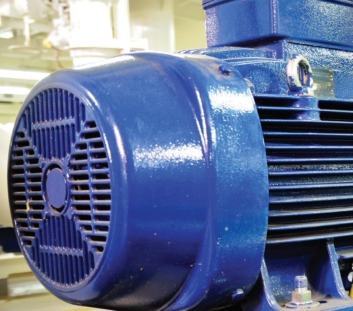
or impeller diameters from standard performance curves are known as affinity laws (full affinity law equations and examples are available in the Australian Pump Technical Handbook).
For variations in speed with a constant impeller diameter, the following rules apply:
• Pump flow rate varies directly with speed;
• Pump head varies with the square of the speed;
• Power absorbed varies with the cube of the speed.
In the affinity law equations, it is assumed that the pump efficiency remains constant. In practice, the
efficiency is generally slightly lower at lower speeds as friction and drag constitute a larger proportion of hydraulic power.
By reducing the impeller diameter, the head and flow rate characteristic of a centrifugal pump can be permanently reduced, without reducing speed.
The reduction in flow rate and head achieved depends on the type of impeller. This is because, apart from changes in peripheral velocity, there will also be changes in the length and overlap of the vanes, the width of the impeller at exit, and also in the discharge angle, in many cases.
It should be noted that the affinity relationships are less accurate for
impeller variation than for speed variation.
If the pump’s net positive suction head available (NPSHA) is less than the net positive suction head required (NPSHR) the pumped liquid will vapourise in the region of the impeller eye (where the local pressure is less than the vapour pressure of the liquid).
In extreme cases this can cause vapour lock, where fluid cannot enter the impeller.
However, more usually, the fluid progresses through the impeller to a region of higher pressure where the vapour cavities implode. This implosion can generate enough force to damage the impeller vane.
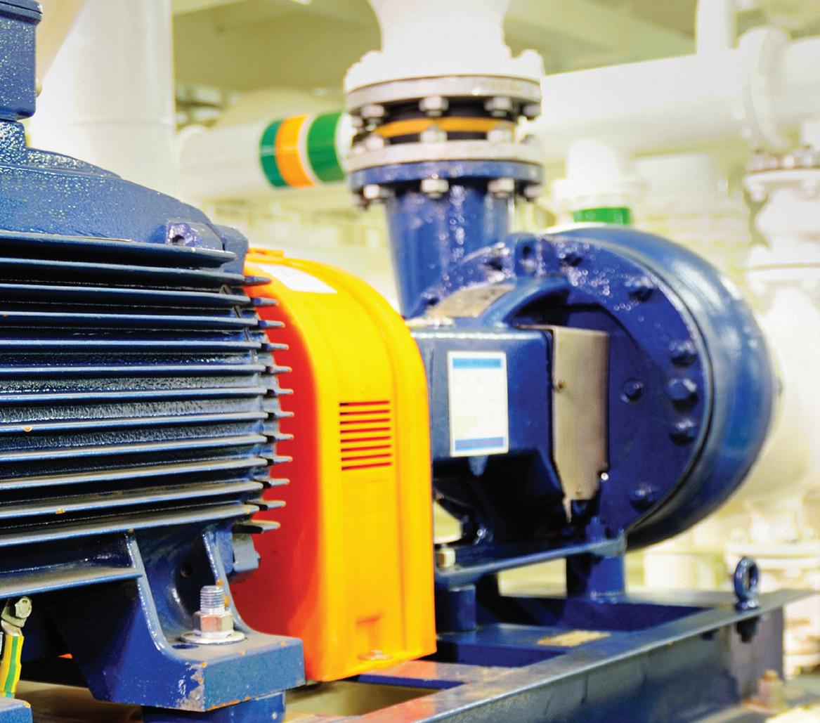
This is known as cavitation.
Cavitation can be caused by excessive suction lift, insufficient NPSHA or operating a pump at too high a speed. The effects of cavitation include:
• Pitting of material surfaces due to the hammering action of the imploding vapour cavities;
• Significant reduction in performance;
• Noise (usually like gravel going through the pump).
Severe cavitation usually results in excessive noise, vibration and damage to the pump, whereas mild cavitation may cause only a small reduction in pump efficiency and moderate wear of pump components.
Cavitation for rotodynamic pumps
generally occurs in the eye of the impeller. In reciprocating pumps, it usually occurs at the beginning of each stroke within the pump barrel or cylinder. In rotary pumps, cavitation will occur if by the end of the opening phase a rotating pocket is not filled with liquid.
In multistage pumps, cavitation normally only affects the first stage.
Although it is recommended to operate a centrifugal pump within its practical range, there are some circumstances where pumps can operate below the minimum practical flow (i.e. near or below minimum continuous flow, towards valve shut head).
If there is insufficient liquid passing through a pump, its temperature will
rise to the point where the liquid will boil. This has the potential to cause serious internal damage to the pump, including seal or bearing failure.
To set a minimum continuous flow for a centrifugal pump it is necessary to calculate the temperature increase at low flows to the point where enough liquid is flowing through the pump to remove enough heat to prevent the internal temperature for rising.
Further information and detailed diagrams, equations and schematics can be found in the Australian Pump Technical Handbook, available from the PIA website. In the next edition of Pump Industry, we explore the characteristics of positive displacement pumps.
In the last article we gave a quick introduction to piping systems and the parts that are in every piping system. Every piping system is made up of three elements: the pump elements, the process elements and the control elements. Each of these elements work together to meet the needs of the process system. If these elements work nicely together then the system will be trouble free, but if they don’t work well together chaos will ensue.
For the next series of articles, we will look at each of the system elements in detail; we’ll start out by looking at the pump elements.
As previously mentioned, the pump elements include the pump, a drive adding energy to the pump, the pump seals and other supporting equipment. In this article we will focus on the pump and drive, specifically rotodynamic pumps driven by electrical motors.
The pump element supplies all the fluid energy to the system required by the process and the control elements. The pump drive takes power from an electric motor in which the electrical energy from the plant power grid is converted to mechanical power at the motor shaft. The motor shaft is connected to the pump shaft where the mechanical power is
used the move the impeller.
In a centrifugal pump, the process fluid in the pump suction is pulled into the rotating impeller. The rotating impeller causes the fluid to accelerate, converting some of the impeller’s mechanical energy into kinetic energy. The accelerating fluid moves from the center and out to the tips; in looking at the cross sectional area between the impeller vanes you can see the cross sectional area increases and as such they convert some of the fluid’s kinetic energy into potential or pressure energy.
After making it to the tips of the impeller the fluid velocity
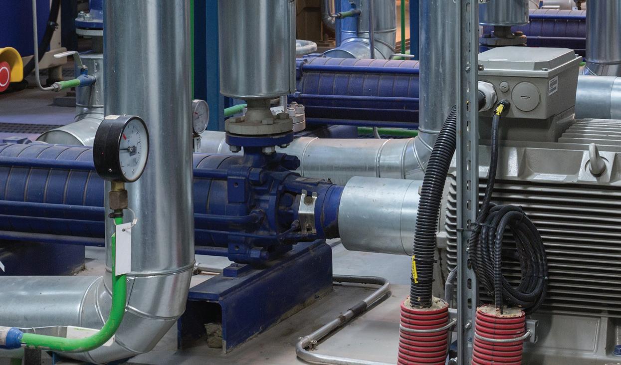
is at its highest. In the volute area of the pump more of the fluid’s kinetic energy is converted potential energy causing a further increase in the fluid pressure. As you can see, the pressure is created within the pump’s impeller and the volute with typically two thirds of the pressure being developed in the impeller and the rest coming from in the volute.
What is so nice about a centrifugal pump is that it always operates as described on a pump curve. The pump curve provides a graph showing the pump head and efficiency as a function of the flow rate through the pump. Figure 1 is an example of a typical pump curve; the data shown is for a 222mm diameter impeller taken at a rotational speed of 2950rpm.
The flow rate through the pump is entered on the x-axis, the head developed by the pump is shown on the left y-axis, and efficiency at which the pump converts the mechanical energy supplied by the pump shaft to the fluid energy is displayed on the right y-axis. Looking at this curve, with a flow rate through the pump of 100m3/hr, we can see the pump develops 61 metres of head and has an efficiency of 75 per cent.
What is so important about the pump curve is the pump will always operate on the pump curve. The pump curve can also provide a flow rate at a different value of head. Looking at the head axis on the pump we can see that at 50 metres of head the flow rate through the pump is 135m3/hr.
The pump head is not affected by the density of the process fluid. The pump curve is always tested with water at standard temperature and pressure as the test fluid. If the density of the process fluid is 900 kg/m3 the pump the head developed by the pump will still be as listed on the pump curve. Conversely if the process fluid has a density of 1,100kg/m3 the pump head will still follow the pump curve.

One final point, the pump’s performance is stated in fluid head but plant pressure gages read out in bars. As a result, to determine the pump head, you will need to convert from pressure units to metres of head.
This provides us with basics of the pump curve. In future articles we will see how the pump and process elements work together to determine the balance flow rate through the system. After that we will learn about how to adjust the flow of the system using control elements.
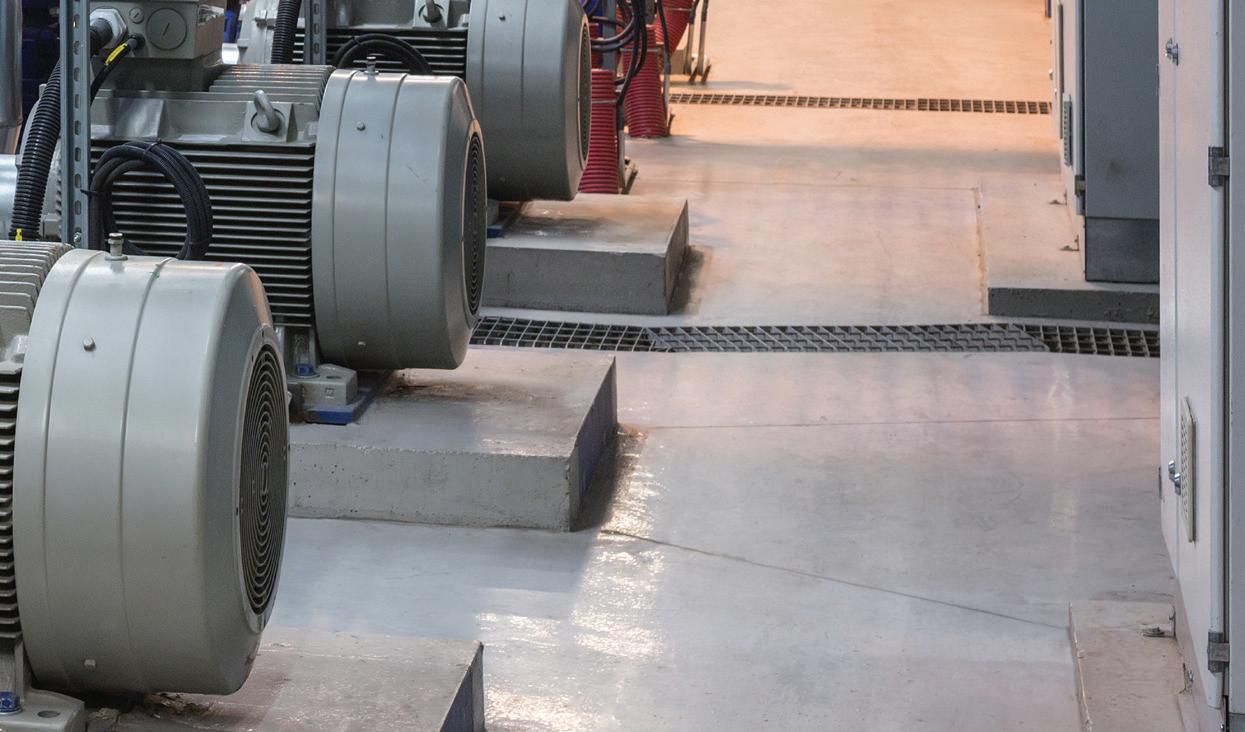
The international community increasingly recognises water as one of the major risks facing the world, with water ranked by the World Economic Forum as the top global risk over the coming decade. The growing attention to water challenges provides an opportunity to shape the direction of our common water future. Water professionals have a key role in delivering the wise water management of the future, and to turn the global water crisis into a once-in-a-generation opportunity to drive sustainable development at an unprecedented scale.
The water wise world satisfies the needs of human activities and ecosystems in an equitable and sustainable way. To get there, we need to dramatically reduce the number of people with no safe access to water and sanitation. We need to reduce the amount of untreated used water, and water wasted from dripping pipes and leaking waterways. We need to re-use water that has served its economic purpose and recycle it together with the materials and energy within it. We need to replenish rivers, lakes and groundwater reserves to create the resilience needed to absorb the shocks from floods and droughts.
The Sustainable Development Goals adopted by the United Nations in 2015 will be shaping water policies, practices and research agendas for years to come. Yet, many of us are just starting to grapple with how to translate these ambitious goals into our own work. The 2016 IWA World Water Congress & Exhibition, held in Brisbane, Australia, will emphasize the sustainable development agenda and explore the linkages to the day-to-day work and future ambitions of the water sector.
The demands on water professionals to provide innovative solutions continue to grow. Water professionals, and those
with a professional interest in water, need to stay current by updating and enhancing their skills, knowledge and know-how. The World Water Congress & Exhibition is a rallying point for water professionals grappling with the challenges of delivering sustainable water management now and in the future.
Bringing together science, technology, policy and practice, the congress is a unique opportunity to learn about the latest trends in leading practices, innovative technologies and pioneering science.
It provides a unique opportunity for professional development and networking, and showcases successful examples of delivering clean water to growing populations; cleaning up polluted river systems at scale; industrial water management; public–private partnerships for service delivery; new policies and regulations in emerging economies; and benchmarking of water and wastewater service providers.
Held in Australia, where the water challenges have led to the development of an industry that is innovative and focused on results, Brisbane is a premium destination for water professionals.
This expertise is in demand internationally and Australian organisations and companies providing water management services, technologies and solutions for the water industry are renowned for their innovation, efficiency and capability.
The challenges that face the water sector are shared by all, and will require us to work together with other sectors and a much wider range of stakeholders to deliver sustainable solutions. Only new insights in pioneering science, technological innovation and leading practices can shape the major transformation in water management that is now underway.
See you in Brisbane!


What are the factors that lead to head loss?
The resistance as a liquid flows through a pipe results in a loss of head, commonly called friction loss, and is measured in meters of liquid or head.
Overall head loss in a pipe is affected by a number of factors which include the viscosity of the fluid, the size of the internal pipe diameter, the internal roughness of the inner surface of the pipe, the change in elevation between the ends of the pipe, bends, kinks, and other sharp turns in hose or piping and the length of the pipe along which the fluid travels.
One of the accepted methods to calculate friction losses resulting from fluid motion in pipes is by using the Darcy–Weisbach equation. For a circular pipe:
Where:
hf = head loss (m)
f = friction factor
L = length of pipe work (m)
d = inner diameter of pipe work (m)
v = velocity of fluid (m/s)
g = acceleration due to gravity (m/s²)
• Motor or wall mountable
• Fully programmable on site
• Software specifically designed for pump operation, control and protection
• High level hardware design
• More flexibility and cost savings
• Energy savings up to 70%
• Simple mounting “clip and work”
• Multi-pump capability up to 8 pumps

Ph: 1300 4 BBENG

Deadline: 23 September 2016
ENERGY EFFICIENCY ISSUE
the 2017 Industry Capability
25 November 2016
& GAS ISSUE
TBA
TBA
ISSUE
