pumpindustry

Oil mist lubrication and plant-wide reliability
Pumps in
biopharma:
in search of a vaccine


Oil mist lubrication and plant-wide reliability
in search of a vaccine
Australia?
· INNOVATIVE BRUSHED TECHNOLOGY
· SELF-CLEANING (NO DIVERS)
· LO W OPERATING COSTS (NO AIR BURST)
· INCREASED PUMP EFFICIENCY
· WEDGE WIRE (DOWN TO 1MM SLOT SIZE)
· A USTRALIAN MADE-TO-ORDER (DESIGNED TO SUIT FLOW, CONFIGURATION AND ENVIRONMENT)



Pump Industry Australia Incorporated PO Box 55, Stuarts Point NSW 2441 Australia
Ph/Fax: (02) 6569 0160 pumpsaustralia@bigpond.com
PIA Executive Council 2020
John Inkster – President Brown Brothers Engineers
James Blannin – Vice President Stevco Pumps & Seals
Kevin Wilson – Treasurer/Secretary Executive Officer
Alan Rowan – Councillor Executive Officer – Publications and Training, Life Member
Ken Kugler
Executive Officer – Standards, Life Member
Louise Black – Councillor Envirotech Water Solutions
Geoff Harvey – Councillor Irrigation Australia Limited
Joel Neideck – Councillor TDA Pumps
Mike Bauer – Councillor DynaPumps
Steve Bosner – Councillor Pioneer Pumps
Hem Prakash – Councillor Davey Water Products
Anant Yuvarajah – Councillor ASC Water Tanks
Hello all and welcome to the Winter edition of Pump Industry magazine. An enormous amount has changed since the Autumn edition – changes we didn't expect, nor did we know just how they would’ve had such a profound impact on our lives and businesses. Sadly we’ve almost forgotten about the drought and bushfires as this pandemic has taken centre stage, although with the recent rains breaking the historic drought across the eastern states, the outlook for the agricultural sector has much improved for the winter months.
At the time of writing, Australia’s death toll was 103, equating to four per million people, which is one of the lowest worldwide – by comparison, in Spain the death toll is approximately 615 per million and in the UK it’s 553 per million; staggering statistics.
On 24 March, PIA sent a letter to the PM’s Office, the Federal Water Minister, and the Premiers and Chief Ministers of all states and territories seeking clarification and approval of all Members of PIA to be deemed essential businesses, enabling them to continue operating. We noted that in NSW a service comprising the supply of goods or services necessary for providing any service referred to in paragraphs (a)-(k) in the Essential Services Act 1988 No. 41 broadly applied to pump related businesses. The responses received indicated that our industry was not listed amongst those named on their Restricted List as being nonessential; this was communicated to you, so thankfully we were able to keep our businesses open whilst observing strict protocols for the health and safety of all employees and customers.
Being involved in the water industry I would suggest has been beneficial for most of us, unlike other industries that have seen their revenues flattened. The economic landscape has changed substantially and we know the impact will not be short lived as we enter into a period of uncertainty. It’s imperative that the national and state governments act collaboratively to enable the much needed economic revival. The private sector has been hit hard by this pandemic and many are already starting to feel the effects of a recession.
On the positive side, there have been other developments within PIA; we are now working more closely with Monkey Media publisher of Pump Industry Pump Industry is now the primary source of all PIA news. Previously, PIA has sent Members a regular newsletter detailing PIA activities, events and other information of interest. Earlier this year, Council decided to streamline communication channels and utilise the extensive subscriber base of Pump Industry and will now provide regular updates through its newsletter.
Whilst we have been unable to have face to face meetings, we have planned online activities; the first of these was a free Flow Technology Virtual Conference held on
12 June, 2–5pm where we heard from local and international experts about how to keep process industries and essential services flowing during COVID -19.
Council planned its first ever Pumps & Systems Training Course, which at the time of writing is to be held via a virtual training classroom held 23-25 June, comprising three and a half days in a virtual classroom followed by a one day practical. Upon completion, each participant will receive a Statement of Attainment, a Nationally Recognised Certificate.
Council has also elected to upgrade our website to make it more appealing to current and prospective Members. The website will include a Members listing, Bookstall, Newsletter, and Calendar of Events.
It is with sadness that we note the passing of Roger Withers on 15 April after a short illness. Roger was a stalwart of the industry and owner of Regent Pumps. Roger will be known by most in the pump industry and in yachting circles – he was an icon of the industry spanning several decades. Sad that he was denied the send-off so richly deserved from an industry he spent so much time being part of as only family were able to attend his funeral due to COVID-19 restrictions. In the words of his daughter, the pump industry is missing a titan.
Ken Kugler, our Standards Executive Officer, advises that PIA as a member of Standards Australia’s Pump Committee ME-030 provided feedback to the International Standards Organisation (ISO) regarding ISO 13709:2009 This standard, now over ten years old, is being considered for revision, retention or obsolescence. Being identical to the American Petroleum Institute’s API610 11th edition, it will be interesting to see whether they will remain so in the future – we would certainly expect this to be the case.
Additionally, the government’s discussion paper MEPS for Industrial Pumps is still in the final draft stage and a Regulatory Impact Statement is currently being prepared. Recently some PIA Members have been requested to provide further comments. The COVID-19 crisis has caused delays, so its final release date to industry may be some time off yet.
As you can see PIA is endeavouring to improve benefits to Members with the website upgrade, working more closely with Monkey Media, and providing online activities and training. If you have an idea that you think would benefit Members and the industry at large, please share it with us.
On behalf of the PIA Council and Elected Officers I wish you and your business every success and good fortune as we all endeavour to survive this COVID-19 crisis and return to some degree of “normality” hopefully in the not too distant future.
John Inkster President

The pump industry continues to play a crucial role during the COVID-19 crisis in maintaining essential services, keeping projects moving forward and in the search for a vaccine.

4,607


ABN: 36 426 734 954
204/23–25 Gipps St
Collingwood VIC 3066
P: (03) 9988 4950
F: (03) 8456 6720
monkeymedia.com.au info@monkeymedia.com.au pumpindustry.com.au magazine@pumpindustry.com.au
Editor: Lauren Cella
Assistant Editor: Eliza Booth
Journalist: Kim Ho
Business Development Manager: Rima Munafo
Design Manager: Alejandro Molano
Designer: Jacqueline Buckmaster
Publisher: Chris Bland
Managing Editor: Laura Harvey
ISSN: 2201-0270


The Victorian Government has invested $48.4 million for new water infrastructure projects and environmental works to modernise the state’s water systems.
The investment will fund projects that modernise irrigation, secure water supplies through recycling and stormwater use, assist with bushfire recovery, and benefit the environment across Victoria.
The funding includes $10.4 million funding for Phase 2 of the Macalister Irrigation District Modernisation project.
The Macalister Irrigation District already contributes up to $500 million to Victoria’s economy each year.
Ongoing investment will ensure the project will be completed, supporting farmers and creating local jobs.
The modernisation works improve productivity and efficiency for irrigators, save water by reducing leakage, and improve the health of the Gippsland Lakes by reducing nutrient runoff.

Electric

In addition, the package is supporting vital bushfire recovery efforts with $10.3 million invested in restoring waterway and catchment health, and replacing essential infrastructure such as water monitoring stations, emergency water supply points and flood warning gauges.
Native fish habitat and endangered native fish species are also getting a boost thanks to $17 million for environmental waterway works in Northern Victoria.
$10.7 million is also being invested in integrated water management projects to secure water supplies by better using storm and recycled water – from Gunbower to Pakenham to Sunshine and Westernport.
This new funding is part of the Victorian Government’s new $2.7 billion Building Works package, and brings its total contribution for the modernisation project to $46 million, with local irrigators and the Federal Government contributing the remainder of the funding.
The government’s Building Works package will deliver shovel-ready projects – big and small – to get thousands of people back to work across the state as Victoria continues to recover from the Coronavirus pandemic.
Victorian Minister for Water, Lisa Neville, said the funding would create jobs across Victoria by funding projects both in metropolitan Melbourne and in regional Victoria.
“By investing in water infrastructure, we are investing in a bright and healthy future for all Victorians no matter where they live – with increased water security and a healthy environment,” Ms Neville said.
“It’s been an unbelievably tough few months for fire affected communities – this work to restore waterway health and assets is an important part of our bushfire recovery efforts.”

Remote monitoring of weather and system operation
Intelligent adaptive control system to eliminate spray drift
No clogging in high TDS waters and suitable for any pH water Quiet
Enquiries: gjc@gjc.com.au
10 Peekarra Street, Regency Park, SA 5010
Phone: 08 8118 6450 www.gjc.com.au

AWorkSafe New Zealand report into a fatal accident caused by a pressure tank explosion on a farm in 2019 has found that more awareness and education needs to be implemented when working with a pressure tank.
The fatal incident occurred on a New Zealand farm in late 2019 when a worker was replacing a pressure control switch in a water pump shed.
The investigation found that at some point during the replacement, the base of the pump’s pressure tank failed causing an explosion in the pump shed. As a result the worker sustained fatal injuries.
Following the incident, an investigation report was conducted by WorkSafe New Zealand. After extensive enquiries, investigators concluded that the damage to the pump house and the fatal injuries to the victim had been caused by the failure of the base of the water pumps’ pressure tank.
Investigators said that the age of the pressure tank was not able to be accurately determined due to advanced corrosion, but following discussions with the landowner it was determined
that the tank had been in place for approximately 22 years.
The pressure tank was assessed after the incident, and was found to be in poor condition.
A visual assessment of the external surface of the tank showed surface pitting to the top and significant corrosion to the rear surface of the tank consistent with having been in a continuously damp environment for a period of time.

The tank was also fitted with a pressure filling valve at the top, used to pre-load the air pressure above the internal diaphragm and no other valves or
inspection plates were fitted to the tank.
As a result of the incident, WorkSafe New Zealand has requested a suite of testing be completed and has initiated technical test reporting to facilitate the creation of relevant Safety Alerts for release to affected industry groups including the agricultural, horticultural and industrial communities.
The Safety Alerts aim to provide information from health and safety authorities with details of recent incidents to alert relevant industries to hazards and unsafe practices.
WorkSafe New Zealand advised the Safety Alerts will be completed and released in weeks rather than months to ensure that the hazards and risks are recognised and mitigated where possible, and awareness is raised across the various industries that use pressure tanks.
The devastating accident and following report serves as a timely reminder for industries using pressure tanks to ensure that they are using best practices and following all safety guidelines for the health and safety of workers.

The EHEDG certified BCFH range of progressive cavity pumps handles thin to highly viscous products, including those containing soft solids with a low shear action and minimal pulsation which enables accurate flow control. BCFH pumps fulfill the stringent demands of cleanliness in the food, beverage, chemical, pharmaceutical and cosmetic industries.
EHEDG Type EL Class I and 3-A Sanitary Standards certified
Enhanced internal design ensures residue free cleaning with CIP/SIP
Equipment requires less cleaning time compared to other CIP solutions
Easy maintenance due to detachable rotor connection and split suction casing


asWater has commenced upgrade works on the Bryn Estyn Treatment Plant, with an aim to ensure future water security for the area.
TasWater Capital Delivery Office (CDO), Alliance Program Manager, Ian Penman, said the project is going ahead without delay, using all the measures necessary to stay safe during the current COVID-19 pandemic.
“The upgrade of the Bryn Estyn Water Treatment Plant is a crucial part of ensuring we can continue to give our customers safe and reliable water to drink for decades to come,” Mr Penman said.
“We have had water supply challenges in the past, including the need to slow down production to deal with the algae
residue in the warmer months, and below average rainfall which contributed to recent water restrictions.
“The plant upgrade plays an important role in ensuring we can increase water supply and storage, and improve water quality, especially in the hotter months when demand increases.”
This upgrade is the largest single infrastructure project undertaken in TasWater’s history, with an expected investment of up to $200 million over its duration.
“Importantly, at a time when many Tasmanians and local businesses are struggling, it will provide employment for many local contractors who will be involved in the construction,” Mr Penman said.
“The upgrade of this plant means we will have water security into the future, even if we continue to experience dry summers and the continued population growth expected in southern Tasmania.”
The project has been designed to enable future upgrades; additional modules can be added to accommodate expansion of the plant, allowing for future population and supply growth.
TasWater remains committed to safely implementing its capital works program during this pandemic, providing much needed stimulus to the state’s economy and employment market.
The upgrade is expected to be completed in 2023.


The Australian Gas Infrastructure Group (AGIG) is considering an initial investment of $200 million in the Golden Beach Gas Project in Victoria.
The investment will deliver greater gas energy security to the east coast gas market, enhance supply volumes and deliver Victoria a critical gas storage facility to underpin the state’s push to renewable energy.
The move is a partnership between AGIG and GB Energy Holdings Limited (GB Energy), the ultimate owner and developer of the Golden Beach gas field.
AGIG and GB Energy recently announced they have entered a non-binding but exclusive Transaction Process Deed which sets out the process for negotiating and executing documentation for AGIG’s proposal to fund, build and operate the midstream infrastructure for the Golden Beach Gas Project.
This would cover all the plant, property, equipment and activities required for the transmission and processing of gas to and from the field. This work has an estimated development cost of approximately $200 million.
Gas from the Golden Beach gas field could be delivered as early as 2022 to the Longford Gas Hub and its associated strategic pipeline infrastructure, approximately 20km away in East Gippsland.
The parties are also working towards AGIG’s involvement in the estimated $145 million development of the Golden Beach Gas Project’s upstream infrastructure. This covers all plant, property, equipment and activities related to drilling and producing gas from the Golden Beach gas field.
AGIG already operates one of Australia’s largest gas storage facilities, the Tubridgi gas storage plant in the onshore Pilbara region of Western Australia.
AGIG’s Chief Executive, Ben Wilson, said, “AGIG is proud to partner with GB Energy on this project.
“Our planned involvement in this key Victorian energy asset reflects AGIG’s focus on delivering world-class infrastructure across Australia.
“As renewable energy penetration increases, gas demand will become more variable as gas fulfils a crucial firming role. This increases the need for storage.
“AGIG’s experience in delivering WA its largest gas storage facility will be very helpful for the project. Golden Beach’s stored gas will help guarantee future gas supply to customers to meet the domestic market.
“After an extensive period of due diligence, the parties are highly confident of moving the proposals to full commercial outcomes.”
GB Energy’s CEO, Tim Baldwin, said, “AGIG brings a deep understanding of infrastructure projects as well as very recent experience in the delivery of gas storage.
“A long-term collaboration with AGIG will complement the GB Energy team and when coupled with the Origin Energy contracts announced in 2019, ideally positions the Golden Beach Gas Project for the future.
“The project will provide Victoria with new domestic gas supply in the short term. The overall investment in critical energy storage infrastructure will then provide a range of ongoing benefits to an evolving east coast market.
“We welcome AGIG’s interest in GB Energy alongside its focus on infrastructure, and see this as a platform for an ongoing successful partnership.”
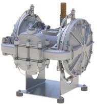
Engineered to deliver industry leading durability and performance, even for the most severe applications and environments.
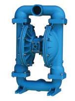
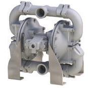
Energy efficient air operated diaphragm pumps with the capability to pump abrasive and viscous liquids make these pumps great for many industries :
- General industry
- Chemical
- Pharmaceutical
- Oil and gas
- Power
- Food and beverage
- Paints, inks, adhesives and ceramics
- Mining and mineral process
- Water and wastewater
We know the importance of choosing the right equipment to match your process. With our extensive range of pumps, first class customer service and ongoing comprehensive support, Kelair Pumps are second to none when it comes to your pumping requirements.

Preliminary works have begun on the $9 million replacement of a 65-yearold sewage pump station, with a new station with increased capacity.
The sewage pump station (previously known as SPS K, now SPS NC1) located on the corner of Sheridan and Lily streets in Cairns North, plays an important role in providing efficient sewer services for the City of Cairns.
This pump station is the largest in operation in the Cairns LGA and pumps more than 600L per second of raw sewage every day through the network, transferring it to the Northern Wastewater Treatment Plant where it is treated.
Given the age of the pump station, the growing population and the increasing density of the city, the pump station requires an upgrade in order to continue servicing the areas across the Cairns CBD and Edge Hill.
The $9 million project includes the decommissioning and demolition of the existing pump station (SPS K), and the construction of the new pump station (SPS NC1) located toward the east of the existing site.
The existing pump station is currently 65 years old and at the end of its useful life.
On completion of the project, the new sewage pump station will allow
increased capacity to cater for the growing demand within the catchment, accommodate future connections within the sewerage network, address odour issues, and continue to provide a reliable sewer network to the community.
Construction timeframe
Works are programmed in two stages being (i) the preliminary works and (ii) the construction works.
Preliminary works are currently underway on site which include location of underground services, surveying and site set out.
The construction phase of the program was expected to commence in mid-April 2020 and to be completed by late 2021.
The new sewage pump station (SPS NC1) includes equipment above and below ground level. Aboveground is

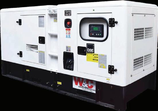
a painted single level masonry block building with pitched roof to house new switchboards for the pump station and a smaller second masonry block building to house Ergon equipment. It also includes reuse of the existing backup power generator in a noise suppression enclosure enabling the pump station to continue functioning in the event of a power outage.
An odour control unit will also be installed which will address odours currently being experienced.
Belowground is a new wet well, pipes and a chamber to house associated underground fittings and valves.
A new pressed point security fence in black will be installed around the new pump station building for safety purposes. The existing driveway will be upgraded and an additional driveway will be installed to create a u-shaped access to service the new pump station.


Melbourne utility City West Water has appointed a new Managing Director, following a national recruitment process.
Maree Lang, who has been acting in the Managing Director role since November 2019, will step up to the role permanently.
Ms Lang has worked with City West Water in senior leadership roles for three years.
In her most recent role as Acting Managing Director, Ms Lang has continued to lead the organisation to successfully deliver essential services to over one million Melbournians, industrial and commercial customers, and Melbourne’s hospitals, sporting and entertainment precincts.
Prior to this role, Ms Lang was General Manager of Infrastructure and Delivery at City West Water, delivering $165 million in infrastructure and shared assets this financial year, managing $1.9 billion of assets and an outsourced maintenance delivery function.
Previously, Ms Lang worked at Melbourne Water for four years, where she led the transformation of its services for urban growth and renewal, and worked in various management roles across customer solutions, sustainability and innovation.
Ms Lang has also held senior leadership consulting and executive roles working across sectors including manufacturing, resources, research, government and industry associations.
Ms Lang holds degrees in Chemical Engineering (Honours) and Commerce from Monash University and a Master of Business Administration (Prof) from Melbourne Business School.
She was also recognised for her achievements as one of Victoria’s Top 50 Public Sector Women for 2018 and more recently was selected to be a participant in the inaugural 2020 Executive Leadership Women in Water Program, sponsored by


the Victorian Minister for Water, Lisa Neville.
City West Water Chair, David Middleton, said Ms Lang was a passionate leader with a wealth of experience in operational leadership, stakeholder engagement and strategy, of which City West Water will continue to benefit.

“Ms Lang’s leadership approach includes a strong future orientation, a commitment to high performance and empowerment, a belief in adaptation and innovation and a determination to be an authentic and inclusive leader,” Mr Middleton said.
“As a member of the City West Water Executive team for the past three years, Ms Lang has led and sponsored critical culture, leadership, safety and business transformation programs to deliver on our strategic outcomes.
“Combined with her water sector experience and a diverse and commercially driven background, Ms Lang has demonstrated her ability to set direction and lead transformation and growth in complex and changing environments.”
On her appointment, Ms Lang said she was “thrilled” to be formally stepping into the Managing Director role.
“My time at City West Water has shown me our organisation is committed to the diverse communities we service across Melbourne’s CBD and rapidly growing western suburbs,” Ms Lang said.
“I look forward to working with the Board and Executive team as we innovate and adapt to new opportunities in delivering exceptional services for City West Water’s customers.”
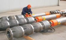
Layne Bowler vertical turbine and submersible pumps have a proven record under the most demanding and toughest of conditions.
VERTICAL TURBINE PUMPS
• Flows to 7,500 L/Sec
• Heads to 500 m
• Power to 1000+ kW
• Temperatures to 150°C
• Bowls Diameter up to 45 inch
Applications
• Irrigation
• Water supply
• Process water
• Geothermal
• Cooling towers
• Fire protection
• Marine
• Water treatment
• Dewatering
• Flows to 140 L/Sec
• Heads to 200 m
• Power to 110 kW
• Bowls Diameter in sizes 6”, 7”, 8” and 10”
Applications
• Irrigation
• Deep well water supply
• Inline booster
• Service water
• Dewatering

Brown Brothers Engineers have innovative solutions whatever your application. Contact us today about your requirements.
The COVID-19 pandemic has brought about a number of unprecedented changes, resulting in disruption to the way workplaces operate as well as delays in materials and equipment from overseas. For these reasons, it has become more important than ever for pump end users and engineers to keep pumps running smoothly and efficiently during this time to keep our lights on, water and sewerage services operating, and process industries running. With this in mind, Pump Industry magazine organised the Flow Technology Virtual Conference, bringing together local and international experts to share their knowledge on keeping services flowing through the crisis.
On 12 June, over 150 pump end users, reliability engineers, rotating equipment engineers and other industry professionals tuned in to explore the importance of maintenance, reliability and condition monitoring, and what they need to know, and can do, to maintain service and supply and reduce equipment downtime.
Despite the challenges of social distancing, and gathering and travel restrictions in place to varying extents across Australia, attendees – no matter their location – were able to watch the virtual conference live via Zoom, with many others accessing the recording to watch at their leisure at a later time. A lot of valuable information was exchanged and there was plenty of social interaction through the in-built Q&A function. The major benefit of this format being that people who may also normally be unable to travel for live events, were able to tune in and learn from some of the industry’s best.
The virtual conference kicked off with Pump Industry Australia (PIA) President, John Inkster, providing the welcome remarks. As the peak industry body for pumps and associated equipment companies in Australia, John was able to provide insight into how the industry as a whole has been coping and adapting to the COVID-19 crisis.
The local keynote speaker was Ron Astall, Sales & Contracts Manager at United Pumps Australia. Ron is well known in the Australian industry as a regular trainer and speaker at national and international technical seminars, and as a former President of the PIA and co-author of the PIA Pump Technical Handbook. With a long career in the industry with experience in engineering, contract management,
applications, sales, marketing and quality assurance, process and petrochemical industries, and the development and implementation of related QA and Contract Management Systems, Ron provided attendees with an interesting and engaging presentation about identifying persistently problematic pumps and what to monitor to prevent trouble before it happens.

Attendees then heard from Ray Beebe. With 28 years’ experience in power generation and over 25 years’ experience lecturing undergraduate students in vibration, rotodynamic machines, mechanical design, etc., and leading the Maintenance and Reliability Engineering postgraduate program at Monash University and the Federation University Gippsland campus, Ray’s informative presentation gave attendees practical knowledge condition monitoring to improve equipment reliability.
Despite the travel restrictions in place due to COVID-19, the benefit of the conference taking place online was that attendees could still hear and learn from an international expert. Heinz Bloch, Consulting Engineer at Process Machinery Consulting, provided a presentation from the US. He has worked as a mechanical engineer since 1962, and authored or co-written over
750 publications, among them 21 comprehensive books on a variety of topics, including practical machinery management, failure analysis, failure avoidance and optimised lubrication for industry. He gave practical advice on implementing reliability practices that attendees were able to take back to their workplace.
The final speaker for the day was Malcolm Robertson, Managing Director at Robertson Technologies. He is a trained physicist and electronics engineer, and has formed companies in South Africa, the UK and Australia. He has developed and manufactured innovative instrumentation to measure pump performance. With remote monitoring of pump performance now more important than ever, Malcolm’s experience in this area provided great insight into this topic and how engineers can utilitse technology to maintain assets without needing to travel to the site.
The Flow Technology Virtual Conference was well received by all who attended, and the team at Pump Industry magazine would like to thank all the speakers for sharing their knowledge and experience with everyone, as well as all the sponsors whose support allowed us to run it free of charge. We would also like to thank all the attendees who tuned in live or watched the recorded conference later.
Digital conferences have quickly become popular as a way to remain connected and learn while we have been unable to meet in person. Here at Pump Industry, we will look at hosting another virtual conference in the near future, so keep an eye on our website, www.pumpindustry.com.au, and our newsletter to find out more information when it is released.
If you missed the live conference, a free recording of the conference is available at https://www.pumpindustry.com.au/flow-technology-2020.


You want a trusted name when it comes to providing engineered power transmission products that improve productivity and efficiency. Rexnord provides superior products for your industrial applications world wide. We work closely with you to reduce maintenance costs, eliminate redundant inventories and prevent equipment downtime.

Rexnord® Falk® Steelflex® Grid Couplings — known for durability in critical applications, proven performance and versatile design. With replace-in-place design, Falk Steelflex Grid Couplings offer a low-maintenance solution for any application in the pump industry.
Rexnord Falk Lifelign® Gear Couplings — triple-crowned teeth are crowned on the root, tip and face to articulate freely and minimize wear caused by misalignment. By eliminating tip-loading while reducing backlash and radial clearances, Lifelign’s triple-crown teeth can help protect equipment from damaging loads.
Contact Rexnord today to see which coupling is right for your application. Tel 02 4677 6000

Pumps have played a crucial role throughout the COVID-19 pandemic helping to keep essential services running, and food and products available to people, but another important area where pumps will have a major impact is in the biopharmaceutical industry which is hard at work manufacturing a vaccine so society can return to normal. Here, we look at four commonly used pumps that are found in biopharmaceutical applications.
Pumps are used in biopharmaceutical processes to move fluids – such as buffer, media and water for injection –through tubing to the process equipment. Due to the need to maintain hygiene and sanitary standards, they must be able to prevent contamination and be able to be validated. To achieve this, they may use single-use components or be designed to be cleaned easily.
There are several types of positive displacement pumps commonly used in the biopharmaceutical industry including peristaltic, diaphragm, rotary lobe and piston pumps. Peristaltic pumps
The term “peristaltic pumps” refers to hose or tube pumps, and are commonly used in biopharmaceutics for applications such as reagent and product dosing, and blood transfer. Although there are specific differences between hoses and tubing, these terms are generally used interchangeably.
Peristaltic pumps are self-priming rotary positive displacement pumps, and have a hose that is located in the tubing bed between the rotor and housing. The rotor has a number of “rollers” or “shoes” attached to the external circumference.
During operation, the liquid is trapped between these shoes or rollers, and as these move across the hose, the hose is occluded, pushing the liquid along. The hose behind the shoe or roller recovers its shape, creating a vacuum and drawing more fluid in.
As the fluid is completely contained within the tube or hose and connectors, process validation is simplified.
For biopharmaceutical processes, while the hose or tubing can be treated as multi-use, where it is cleaned and sterilised between batches, it is typically treated as singleuse and disposed of after each process to prevent crosscontamination with following batches. As maintaining fluid path sterility is key in these processes, the hose or tube is manufactured from biocompatible materials that meet purity requirements.
The flow rate is determined by multiplying speed (rpm) by the volume of trapped liquid. The volume moved is consistent, even under a wide range of viscosities or densities. The flow rate is therefore directly proportional to the gearbox speed.
The size of the hose or tube is determined by fluid viscosity and the deliverable flow, with higher viscosity products requiring a large bore size tube, but a low running speed. In

downstream processing – including tangential flow filtration and high performance liquid chromatography – flow linearity with only trace pulsation and a wide pressure range is desired.
The key advantage of peristaltic pumps is the sealless design with no moving parts in the pumped fluid. Discharge pulsations are low, self-priming is good, the pump can handle high viscosities, and capacity accuracy is maintained for good process control. The pumps can also be run dry.
As they are low shear – unlike centrifugal, gear or other types of rotating pumps – cell suspensions will not be damaged when they are circulated or pumped, making them ideal for biopharmaceutics where product being pumped can be damaged by high fluid velocities or contact with mechanical parts. While hosing or tubing occlusion can still cause cell death, this can be mitigated by reducing pump speed and increasing hosing or tubing diameter.
The amount of shear allowed is dependent on the sensitivity to shear forces due to flow of the product being pumped. For example, peptides and small proteins are relatively insensitive, while mammalian cells and vaccines can be very sensitive.
Selecting the right sized pump is one way to ensure shear is kept to a minimum to maintain product integrity. Low shear is further achieved by lowering the pump’s speed and increasing the tubing bore size to reduce fluid velocity.
Hose or tubing life and material are critical for maintaining performance as a failure can cause the loss of an entire campaign, but these are also the biggest concerns for peristaltic pumps in biopharmaceutical applications as the main wearing part of the pump is the hose or tube. If properly and conservatively selected, the hose, and therefore the pump, will give long operating life between overhauls. Preventative maintenance is also key. But if care is not taken, hose life can be short.
Diaphragm pumps are a type of reciprocating positive displacement pumps and fall under the category of metering pumps. They are used for biopharmaceutical applications such as chromatography, buffer inline dilution, homogenisation, injection of fluids into extruders, coating operations, filling, caustic dilution, and aseptic transfer of proteins, cells, and other materials.

There are various types of diaphragm pump, including air-operated-double-diaphragm, mechanically actuated, hydraulically actuated, electromagnetic (solenoid), and electronic.
• Air-operated-double-diaphragm (AODD): These pumps are used in biopharmaceutics for transferring fluids from one place to another and for ultrafiltration or diafiltration. They consist of two pumping chambers that are alternately filled and discharged by the movement of flexible diaphragms. Compressed air is alternately fed to, and vented from, air chambers on the opposite sides of the diaphragms to create the pumping action. They are also self-priming, sealless and can be run dry. However, they do not have volumetric control
• Mechanically actuated: In these pumps, a reciprocating connecting rod or cam, located within an oil bath lubricated gearbox, displaces a diaphragm over a given length within the pumping chamber. Via the hydraulic opening and closing of the internal inlet and outlet check valve, this accurately displaces a continuous injection of the liquid to the process, the amount of which can be adjusted either manually or automatically. Typically, these pumps are driven by AC motors. These pumps are sealless, which can be very important when pumping hazardous or expensive fluids, and are capable of running dry
• Hydraulically actuated: This type of pump combines the benefits of the sealless construction of the mechanical diaphragm pump with higher pressure capabilities. The diaphragm is hydraulically coupled to the plunger so that the plunger displaces oil within a cavity, which in turn displaces the diaphragm. This design requires a positive flooded suction and normally features an inbuilt pressure release valve for pump protection
• Electromagnetic (solenoid): In this pump design, the diaphragm is displaced by energising/de-energising the restricted movement of a plunger within a solenoid coil. The plunger is mechanically linked to a diaphragm that displaces the liquid volume on a noncontinuous (on/off) principle. Capacity adjustment is achieved manually or by a range of direct automatic input signals
• Electronic: Based on the same principles as the mechanically actuated diaphragm pump, this design incorporates both manual and electronic control features similar to the electromagnetic diaphragm pump by varying the “off period” of time of a single phase AC motor Furthermore, diaphragm pumps can be multi-use or single-use. Multi-use pumps are still commonly used in the industry, and have housings made from stainless steel that can be reused after cleaning in place. Single-use pumps are ideal if there are frequent or fast product changeovers required.
They have chambers made from plastic and are designed to be used for a single process or batch before being replaced. The benefit of this is that they save time and money as cleaning and cleaning validation are not needed, and there is no risk of cross-contamination between batches.
Rotary lobe pumps are common in the biopharmaceutical industry due to their high sanitary qualities, high efficiency, reliability, and good clean-in-place (CIP) or sterilise-in-place (SIP) characteristics. They have large pumping chambers, and if wetted, they are self-priming. Furthermore, like peristaltic pumps, they are low shear, making them ideal for sensitive products.
When operating rotary lobe pumps, the fluid flows around the interior of the casing. The benefit of these pumps is that the lobes don’t make contact due to external timing gears being located in the gearbox, and since the bearings are out of the pumped liquid, pressure is limited by bearing location and shaft deflection.
A shaft seal is required for each shaft which are usually special short designs to minimise shaft length and overhang.
Rotary lobe pumps are manufactured with a variety of lobe operations including single, bi-wing, tri-lobe and multi-lobe.
Rotary lobe pumps designed for sanitary uses can be broken down depending on the service and specific sanitary requirements, including 3-A, EHEDG and USDA.
These pumps offer reversible flows and can operate dry for long periods of time. Flow is relatively independent of changes in process pressure so output is constant and continuous.
Since the lobes don’t make contact and clearances are not as close as in other positive displacement pumps, internal leakage is increased and volumetric efficiency decreased when pumping low viscosity liquids.
High-viscosity liquids require considerably reduced speeds to achieve satisfactory performance. Reductions of 25 per cent of rated speed and lower are common with high-viscosity liquids.
Piston pumps work by cycling through a suction phase and a pressure phase to move fluid. They are well-established and popular in all areas of biopharmaceutical processes, in particular liquid filling, due to their reliability and accuracy. However, compared to other pump types, there is greater concern of cross-contamination as they require regular maintenance and disassembly for cleaning and sterilising. Therefore, multiple piston sets need to be managed: one for each injectable drug being filled.
Due to these drawbacks, there has been a shift towards peristaltic pumps for these applications.
Long-time pump professional Roger Withers passed away from pancreatic cancer on 15 April 2020, aged 78.
A well-known figure in the Australian industry, Roger was passionate about pumps and the pump industry. He was the Owner of Regent Pumps and took great pride in the company as an Australian-owned and operated pump manufacturer since it opened in 1948.
In a social media tribute, Roger’s daughter, Rachel Withers, called him a strategic mastermind, recounting how he engineered his final goodbye by breaking out of hospital two weeks prior and going to a nicer hospital, allowing the family to say goodbye during a time when restrictions to hospital visitors was high.
As it was, he struggled on well past the two months they gave him, making work calls right up until his brain stopped working. I don’t think we’ll ever figure out how he managed to MacGyver his way out of hospital, but he did, and I’m so glad he came home to us,”

“He was playful, daring, iron-willed, generous (to a fault), tireless and definitely some kind of genius. ‘Balls like an elephant!’ someone yelled at the Christmas party when he declared he would fight and beat his cancer. Had it been the beatable kind, we all know he would have.

Rachel wrote.
“The calls I had to make today were hard, but they made it clearer to me than ever that my dad was one of a kind. Anyone who ever worked with him or raced with him was floored that he could actually be gone, and the word icon came up again and again. The pump industry is mourning a titan.
“Over the past few months, many people have told me that they consider him a father figure. I could not be prouder to have been able to share him with so many.”
Along with being a well-loved member of the pump community, he was a supporter of the Australian industry, with the Regent Pumps being a long-term member of the APMA/PIA.



For the first time, Pump Industry Australia (PIA) is offering Australian pump professionals a four -day nationally recognised, competency-based training course, with the inaugural course scheduled to have taken place in late June. The course will provide participants with the knowledge and hands-on skills needed to provide a professional service to those relying on the pump industry for advice, service and products.
In a statement, John Inkster, PIA President, said the new course provides companies with an opportunity to train their staff to a national certificate level in the selection and use of pumps and pump systems.
“A first for the PIA, we are bringing a new level of competency-based training to the industry. The course will benefit those who are looking to make a career in the pump industry,” Mr Inkster said.
“The units being offered are nationally-recognised competencies and will be of value to you and your staff now and in the future.”
The course is being run in cooperation with Irrigation Australia Limited (IAL), Australia’s peak industry body for the irrigation sector and a Registered Training Organisation, who will facilitate the course on behalf of PIA.
“Although the subject titles on offer refer to irrigation pumps and systems, the material being taught is applicable to all pump installations,” Mr Inkster said.
“If your business is in industrial or commercial pumping, the principles of pumping hydraulics included in this course are equally applicable to your business.”
The Pumps and Systems Training Course is a four-day program, with three days of in-class training and one day of practical activities.
Over the course of the four days, participants will complete three

competencies, and upon completion, qualifying participants will be awarded a Statement of Attainment for these.
The competencies to be delivered during the training course are:
AHCIRG340 Install irrigation pumps
This unit of competency describes the skills and knowledge required to install and commission pumps and systems.
It applies to individuals who take responsibility for their own work and for the quality of the work of others; and who must use discretion and judgement in the selection, allocation and use of available resources. All work is carried out to comply with workplace procedures.
AHCIRG435 Determine hydraulic parameters for an irrigation system
This unit of competency describes the skills and knowledge required to determine hydraulic parameters for a pump system.
It applies to individuals who analyse information and exercise judgement to complete a range of advanced skilled activities; demonstrate deep knowledge in a specific technical area; have accountability for the work of others; and analyse, design and communicate solutions to a range of complex problems. All work is carried out to comply with workplace procedures.
AHCIRG438 Select and manage pumping systems for irrigation
This unit of competency describes the skills and knowledge required to operate and maintain pumping systems.
This topic applies to individuals who will analyse information and exercise judgement to select or troubleshoot an existing pumpset or system.
Various pump types and situations will be analysed, and the attendee will have accountability for the whole process and analyse, design and communicate solutions to a range of complex problems. All work is carried out to comply with industry best practices.
Adapting to change
PIA and IAL have been quick to adapt to the social distancing restrictions put in place by the government over the past months to launch the course. The June course made use of online video platforms to move the in-class activities to online, and the practical session will be held at a later date at a venue in the participants’ capital city, following easing of government restrictions on gatherings.
Pending future easing of restrictions, future courses will be run in the in-class format.
For more information and to keep up to date with future course dates, visit pumps.asn.au

Ebara is known worldwide as one of the largest and most diverse manufacturers of custom, industrial and general purpose pumps. Since its beginnings in Japan over 100 years ago, the Ebara Corporation has been a major supplier of pumping equipment to Japanese industry, and over the last 50 years expanded to all industrial markets worldwide.
Ebara has factories and sales offices in six continents and has recently undertaken a major globalisation of its standard industrial product range. This includes the introduction of a new range of EN733 end suction pumps, and a redesigned and economical vertical multistage pump.
In Australia, the Ebara name has been renowned for its quality and reliability. The Ebara Pumps Australia standard product line has been sold and supported in Australia for over 30 years.
Ebara continues to supply world-leading pumps.
Two recent examples are shown below:
Ebara has supplied some of the world’s largest boiler feed pumps to supercritical power plants in China. These were the first single pumps capable of supplying boiler feed water to an entire 1,000MW power plant.

Discharge: 500mm (20") Power: 37,000 kW (37 MW)
Duty: 3,200t/hr @ 3,800m.hd.
Many Ebara custom pumps have also been installed in Australian and New Zealand power stations and in industry for over 40 years with trouble free operation.
The new products have been designed to global standards to suit the world market, and are manufactured at Ebara owned and managed factories in Europe and South East Asia. This is building on the 100 years of Japanese technology and engineering expertise obtained in the manufacturing of high-end custom pumps.

Ebara has recently manufactured its largest submersible pump in terms of length and motor power. This will be installed at Lake Mead to supply water to Las Vegas, US.
Diameter: 900mm Motor Power: 2,500kW
Duty: 79m3/min @ 132m.hd Length*: 130m
Length*: The pump is assembled with 24 x 5.2m column pipes
Ebara


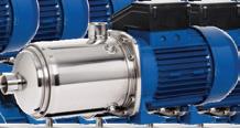


When it comes to choosing the right positive displacement pump for an application, efficient, reliable and trusted products are integral qualities to look for. Finding a manufacturer with established expertise and knowledge can make the process a lot easier, saving you time and money.
For Roto Pumps – a global manufacturer of positive displacement pumps – a strong foundation of experience; efficient, reliable and readily available stock; and costeffective solutions have seen it become a global leader in the pump industry.
In 2001, Roto Pumps established a local branch in Australia with warehouse, assembly and marketing infrastructure to provide positive displacement pumping solutions to various industries across the country.
The new Australian market presented its own challenges, with strong competitors, but Roto Pumps was not new; it had a rich legacy of over 50 years experience internationally, with a large number of screw pump installations in critical applications across the globe to draw from.
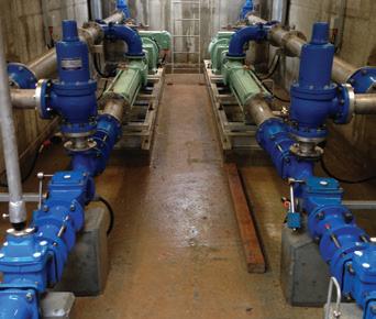
To gain a strong foothold in the Australian market, Roto Pumps focused on providing customised engineered pump packages, strong service support and ensuring ready availability with optimum stock levels of pumps and spares. Roto Pumps Australia also established an intensive network of distributors and channel partners.
Roto Pumps Australia’s capabilities:
A pioneer in manufacturing
Known for pioneering the manufacturing process of progressive cavity pumps in India in 1968, Roto Pumps has continued to grow into one of the most trusted global leaders in the field. Today, the company supplies pumps to more than 10,000 customers across 50 countries and have installed over 250,000 pumps globally.
Throughout it’s five decade journey, Roto Pumps has also established operations in the UK, South Africa, US, Germany and Malaysia thanks to its highly dedicated team and passion towards research and development of highly efficient positive displacement pumping solutions.
Now, with 18 years of experience in the Australian market, Roto Pumps has established itself as experts in application engineering i.e. understanding complex pumping requirements, handling critical media, and optimising pump lifecycle cost. It is also credited with supplying customised pumps in different materials like Hastelloy, Super Duplex, Tungsten Carbide Coatings, and Double Hard Chrome Plating etc.
In addition to pumps, its stators are world famous for their stringent quality.
• 18 years of strong presence in Australia’s robust supply chain network
• Strong sales and service support team in Australia
• Readily available pumps and parts stocks
• Cost-effective and customised engineered packages
Roto Pumps’ in-house captive elastomer manufacturing unit manufactures world-class quality stators conforming to international standards. To deliver quality stators, Roto Pumps procures raw material from certified vendors and has implemented strict process control and quality checks.
A leader of innovation
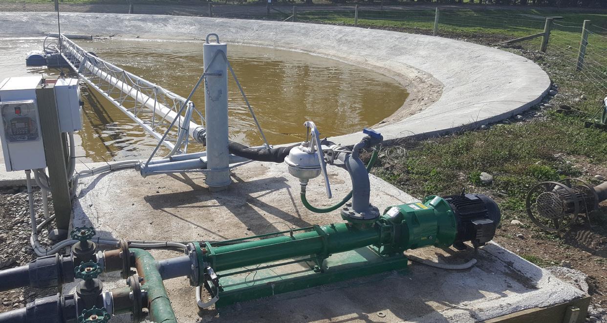
Roto Pumps is also a leader of innovation in pumping solutions. Some of its key innovations include: Roto KwikMaintenance in Place Pumps for quick maintenance of Roto Progressive Cavity Pumps without removing pipelines; the Tirrana Agriculture Progressive Cavity Pump range for agriculture and light industrial duties; and the upgraded Biomix and Biomass Progressive Cavity Pumps.
Roto Pumps believes in customer satisfaction and has a team of experienced application and sales engineers in Australia who completely take care of every customers’ concern right from receiving the inquiry to providing prompt after-sales support.


2,50,000
Waterhammer – which is a pressure surge within a piping system – can cause significant damage to any system not designed to accommodate such stresses, including burst pipes, damaged valves and more. Having a clear understanding of what is causing the phenomenon in a particular installation is key to identifying the right solution.
Waterhammer occurs when a fluid in motion is forced to stop or change direction suddenly. This often occurs when a valve closes suddenly at the end of a pipeline system, and a pressure wave grows in the pipe.
Because of this, pump starts and stops can cause waterhammer, as a rapid change in flow and system pressure can cause the sudden closure of check valves, while changes in the direction of flow can induce water column separation.
Pressure tanks, surge chambers and similar accumulators can all mitigate the effects of waterhammer, but prevention is often a better strategy.
Valve closure time significantly impacts the likelihood of damaging water hammer occurring, as the more slowly the valve is closed, the less significant the increase in pressure will be, thus reducing the incidence and intensity of waterhammer. Controlled valve closure can be achieved manually or by use of motorised valves.
Soft starters and variable speed drives (VSDs) can be used to control the speed of the pump during starting and stopping. This allows for a more gradual change in pump speed to prevent water column separation, flow reversal and sudden check valve closure.
Soft starters and VSDs can provide a range of advanced motor and system protection functions as well as monitoring and control options.
The effectiveness of electronic speed control in the reduction of waterhammer is determined not only by the type of technology within the soft starter or VSD, but also by the pump and system curves.
With a ‘steep curve’ pump, a large change in pressure produces a small change in flow. Conversely, with a ‘flat curve’ pump a small change in pressure will result in a large change in flow.
To help abate waterhammer in a system, a steep curve pump should be used wherever possible. The relationship between pressure and flow rate for such pumps makes precise control of the flow rate via control of pump speed much easier.
Soft starters run the system at full speed during operation, controlling the speed during pump starting and stopping only. Once the system reaches full speed, the soft starter is typically bypassed and operates with very high efficiency, thus reducing running costs. Soft starters also come at a lower cost than VSDs and do not necessitate the use of costly filters – they should be the preferred method of electronic speed control for the mitigation of water hammer.
The most advanced soft start (and stop) mode is direct acceleration and deceleration control, which is ideal for the elimination of waterhammer because it enables selection between a variety of starting and stopping profiles, depending upon the unique characteristics of the pumping system. Furthermore, the ability to select and adjust a variety of control strategies makes it simple to tailor operation for optimal results no matter what the system characteristics.
For more information about how to mitigate and prevent the effect of water hammer, visit ipdgroup.com.au.

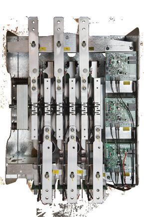
AuCom’s EMX4i now available in the full range of current ratings
And now introducing 1000V soft starters to the EMX4i range
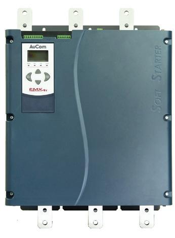

• XLR-8 control to prevent water hammer
• Emergency run mode
• Real time metering & monitoring
• Automated pump clean function
• Extended motor protection functionality
• Clock & calendar scheduling



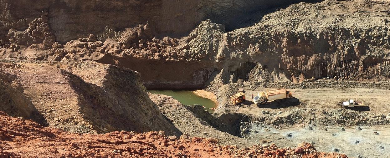
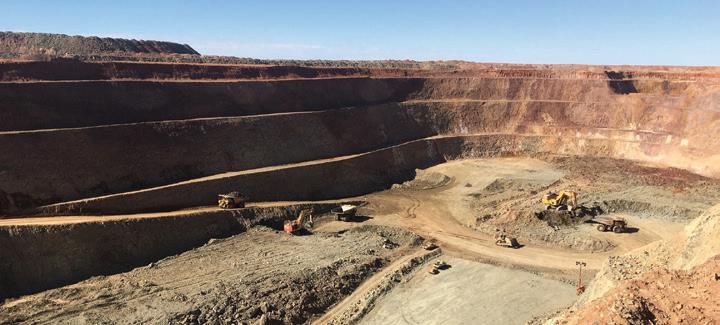
Deep in the centre of Western Australia lies one of the state’s largest single site undeveloped gold projects, the Wiluna mine. Making up part of the larger Wiluna Mining Operation, the Wiluna mine holds great potential for expansion, and Wiluna Mining (formally Blackham Resources), the company responsible for the development of the mine, has big plans for the project. A major expansion of the mine – including dewatering works, and the construction of a tailings storage facility and sulphide flotation plant – is currently underway with the hopes of increasing production to 100,000-120,000 ounces a year of gold concentrate, in addition to the current 70,000 ounces per year of gold dore produced from free milling ore for an annual total of 190,000 ounces of gold, giving Wiluna the potential to become one of Australia’s major gold producers.

The Wiluna Mining Operation
The Wiluna mine is located approximately 750km north-east of Perth. The mine has been active and closed several times over its life, with the first iteration operating from the late 1800s to the early 1900s, and the second iteration from the 1930s to the late 1940s. The mine then remained closed until 1984 when it opened again. It remained active until 2007 when it was put into care and maintenance before reopening from late 2008 to mid-2013 when its owner at the time, APEX Minerals, went into
receivership. Wiluna Mining purchased the mine in early 2014 and it has remained operational since.
The Wiluna Gold Mine has produced over four million ounces of gold from 20 open pits and three underground mines, making it a strong asset for Wiluna Mining. Currently, most of the oxide ores have been sourced from the Matilda and Lakeway mining centres; however, with the new expansion, ores will be increasingly sourced from the Wiluna and the Williamson open pit at Lakeway, which has the potential to significantly increase Wiluna Mining’s resources.
“The Wiluna Mining complex is, in my opinion, the largest single site undeveloped gold project in Western Australia,” Blackham Resources Executive Chairman, Milan Jerkovic, said.
“We have not even explored the underground sulphides below 500m which compared with peers like Jundee and Gwalia, is very shallow.
“There is real potential to significantly increase our resource/ reserves at Wiluna and we have many other sulphide targets, including Regent, that have significant potential.”
By Eliza Booth, Assistant Editor, Pump Industry
Stage 1 of the expansion is expected to produce 750,000 tonnes per year and Stage 2 is expected to double production to a minimum of 1.5Mtpa, pending the release of a feasibility study.
Stage 1 of the expansion project is already underway, with works moving ahead despite the COVID-19 crisis putting pressure on many industries.
Mr Jerkovic said that the resource to reserve conversion drilling has already commenced, as has the construction of the tailing’s storage facility, which currently has four walls but no pumps yet. In addition, the Rod Mill refurbishment has been completed and successfully commissioned.
The dewatering of the East-West pits and underground mine is also well underway and is currently utilising five pumps with a combined capability of pumping around 260L/s of water. These pumps include hired diesel-driven skidmounted centrifugal pumps and one multi-stage pump that is run down a vent shaft.
Since dewatering started last year, 3GL of water has already been removed, with another 1GL to go.
However, other Stage 1 works have been held up including the construction of the concentrator for the sulphide floatation plant, with the pandemic impeding construction. Mr Jerkovic said that the timing on the construction of the concentrator will now need to be assessed according to how quickly Wiluna Mining can mobilise construction crews and equipment when the COVID-19 crisis concludes.
In the meantime, standard Warman pumps and dosing pumps have been procured for the sulphide flotation plant, and the Ball Mill Motor has been replaced after reaching the end of its lifecycle after 20 years.
Following the completion of stage one of the projects, Wiluna Mining will progress to Stage 2 which is estimated to double production of Stage 1 to 1.5Mtpa, equating to circa 220kozpa250kozpa of gold concentrate.
In order to undertake the expansion of the Wiluna mine, Wiluna Mining needed to raise $52 million equity, not a small feat in the current economic climate. However, Wiluna Mining was able to achieve this, with Mr Jerkovic
saying it was a terrific achievement, especially in the worst two months the market has seen since 1987.
“We are fortunate to have a greatly supportive major shareholder in Wilhelm Zours of Delphi who has backed us to the hilt in the last eight months. Mr Zours is a very smart and canny investor and has done his homework, been to site, spoken to our management team, and has decided to back the team and assets at Wiluna Mining when very few people would,” Mr Jerkovic said.
“There is, in some circles, still this view of Wiluna that it is a dud and that all of us at Wiluna Mining have no idea what we are doing.”
However, Mr Jerkovic said that those in the industry who understand the company’s strategy will undoubtedly see the potential of Wiluna Mining and the Wiluna Mining Complex.
“I believe the really smart people in the industry who understand our strategy and see the potential of Wiluna with the right strategy, have done their own due diligence, visited the site and spoken to the Wiluna Mining management team, and seen unlimited potential in the company; and that gives us great confidence going forward that we are on the right track to building something really substantial here. The naysayers will miss the boat here as they usually do,” Mr Jerkovic said.
As COVID-19 has swept across the world, many industries have felt the impact. For Wiluna Mining, the safety of its staff and local communities remain a top priority throughout the unfolding situation.

“Safety of our people is always a core objective of the company and obviously given the COVID-19 crisis, we must be even more diligent to safeguard all people, including the people of the remote community of Wiluna,” Mr Jerkovic said.
“Maintaining our operations and output is also a core objective for the next 3-6 months whilst we see out this difficult time.”
Mr Jerkovic said the five core objectives of the company from a strategic point of view are the repair of the balance sheet, increase immediate operational cash flow, transition to include gold concentrate production, expand gold production, and undertake exploration and feasibility to fully develop a +250ozpa, long-life gold operation.
“Strategies 2-5 are now our focus. These strategies were established ten months ago when I changed out the old management and set a new direction for the company,” Mr Jerkovic said.
“I set a 24-month timetable for this transformation and we are ten months into it, and so far, we are on track.”
With the aim of becoming a major Australian mining company, Mr Jerkovic said that Wiluna Mining wants to be a highly profitable, professional, efficient and safe organisation for people to work and invest in. The company is also aiming to be an industry leader in all environmental, social and governance related ventures.
Looking to the future, Mr Jerkovic said that the major goal is to build Wiluna Mining into a major mining company with the Wiluna Mining Complex providing the base of its operations.
“My expertise is building substantial, multi-billion-dollar mining companies. We did it at Straits Resources. Wiluna provides the scale to be able to do that again,” Mr Jerkovic said.
“The major shareholders who have recently come on board want us to do that again, build another significant mining company using Wiluna as the key building block.”
However, Mr Jerkovic notes that Wiluna Mining is not looking at other refractory ore opportunities in Western Australia and in other regions for the time being, instead concentrating on developing the potential of the Wiluna Mining Complex before spreading its wings too far.
“There are three main gold systems in the northern goldfields. We control the central belt with the Wiluna Mining complex. To the east of us is Northern Star with Jundee and Bronzewing. To our west is Peter Cook’s Westgold.
“There are several smaller, stranded deposits surrounding Wiluna who are looking for processing solutions and are probably not of the scale to do it on their own, both free milling and sulphides deposits, and we are talking to several of them now about doing deals similar to the one we did recently with GW Resources to provide a treatment solution for them.”
AVAILABLE IN PRESSURES FROM 200 BAR TO 3000 BAR


In April, Galena Mining completed construction of the box-cut for the Abra Base Metals Project, a new lead-silver mine in the Gascoyne region of Western Australia. With site preparations and surface infrastructure construction already complete, the mine is expected to be operational by 2022. Here, we take a look at the mine’s progress so far, and the facilities required for its successful operation.
Discovered in 1981, the Abra lead-silver deposit represents one of the largest undeveloped lead deposits in the world. Abra lies within a granted mining lease, with Galena owning 86.16 per cent of the project. Galena’s vision is to develop Abra into a high-grade, high margin operation by 2022.
The Abra site is approximately 110km from Sandfire Resources’ DeGrussa copper mine, between the towns of Newman and Meekatharra.
The mine will employ pumps in dewatering, dust suppression, earthworks, securing a potable water supply and a wastewater treatment facility for the permanent camp, and in a process plant at the mine will produce a lead-concentrate product that may be transported to the Port of Geraldton.
Feasibility studies, securing investment and surface works
The path to this point has been long, but filled with promise. Galena completed its pre-feasibility study for the project in September 2018, for development of a mine and processing facility with a 14-year life producing a lead-silver concentrate containing approximately 91kt of lead and 760koz of silver per year after ramp up.
Based on an initial capital expenditure estimate of $154 million, the pre-feasibility study modelled Abra’s pre-tax net value at $528 million, with an internal rate of return of 50 per cent.
Progress on the project leapt forward in March 2019, when Kingfisher Capital announced it would invest $10 million into the company, placing the sum in two $5 million tranches at $0.40 per share. Galena then used the proceeds of this investment to accelerate works at Abra.
By July 2019, Galena completed its feasibility study of the project – and the results were promising, pointing to improvements in most key metrics. According to the study, the mine would yield a 16-year mine life, rather than 14. Whilst the estimated capital expenditure increased to $170 million, the estimated pre-tax net value of the mine also grew to $553 million – five per cent higher than the pre-feasibility study’s prediction.
Galena announced in October 2019 that construction works had begun on the approximately $15 million site surface infrastructure program, readying the site prior to construction of the processing plant and development of the mine itself.
Activities carried out as part of this program included:
Site clearing and roadworks
Initial works focused on topsoil clearing and storage, ground preparation at the permanent camp site and various site and access roadworks.
Water supply and wastewater treatment facilities
Galena commenced an initial project development drilling
program in March 2019. The drilling included the construction of three water bores, with test pumping completed and Rockwater preparing a hydrogeology report.
These new works involved equipping the water production bores with pumps and constructing pipelines, together with construction and connection of wastewater treatment facilities.
Establishing the permanent camp
Finally, the initial 80-person accommodation units of the permanent camp were deployed to Abra and assembled on-site, along with the final camp sized kitchen and messing facilities. On-site civil works and connection to services was also completed.
Galena’s Managing Director, Alex Molyneux, said the project was advancing more swiftly than initially anticipated.
“The construction works now commenced at Abra are significant and most of them form part of what might go into a final EPC [engineering procurement and construction] package, so we’re genuinely getting a ‘jump’ on things to fasttrack the overall timetable to production,” Mr Molyneux said.
Employing pumps in the flotation process plant
Primary refined lead is sourced from mines as a concentrate, which then goes through smelting and refining.
In February 2020, Galena’s subsidiary, Abra Mining, announced it had awarded GR Engineering Services (GRES) a $74 million conditional engineering, procurement and construction contract for the supply of a 1.2 million tonne per annum lead process plant, along with ancillary infrastructure.
Abra will use a lead sulphide flotation process plant to refine the lead concentrate.
GRES designed a process flowsheet that would produce a single high-value, high-grade lead-silver concentrate at maximum recovery. The process for the creation of lead/silver concentrate involves the following steps:
• Three stages of crushing with fine ore bin storage and emergency stockpile with feeder
• Single stage ball mill with a flash flotation cell treating cyclone underflow
• Flotation and concentrate regrind to produce the initial lead/ silver concentrate
• Concentrate dewatering utilising a thickener and a filter to make the concentrate transportable
• Tailings thickening and storage in a designated facility
Early grade recovery modelling of flotation data suggests that the process plant will recover between 93 and 94.7 per cent of the lead. The concentrate is expected to contain 73 to 75 per cent lead and approximately 200g/t of silver.
The processed concentrate will then be trucked via public roads to the Port of Geraldton.

Abra’s estimated net raw water requirement is approximately 23.4L/s, which is expected to be supplied by aquifers within 7km of the proposed processing plant.
Galena anticipates site water needs will change as the project transitions from construction, into ramp up to a peak, and finally reducing to a steadystate.
During the approximately 15 month construction phase, the main water requirements will be potable supply to the village, mining, earthworks, dust suppression and concreting. Here, water demand is expected to be approximately half that required at steady-state production (that is, around 11L/s).
The project water requirement is projected to peak at 28.4L/s during operational ramp up, scheduled in 2022. At this time, there is initially expected to be a reduced return water from the tailings storage facility and nil mine dewatering.
Galena plans to develop additional sources of water to increase the capacity of the current production bores – as well
as to provide long-term redundancy for the three current production bores during the steady-state period.
Further drilling to increase confidence
Following its feasibility study, Galena has conducted further infill drilling and commissioned an independent, updated JORC Code-compliant Mineral Resource estimate to increase confidence in the early years of the mine plan.
The company’s 2019 Project Development Drilling Program, consisting of 43 drill holes for a total of 18,255 cumulative metres of diamond core drilling, yielded positive results. The estimate showed an approximately eight per cent increase in contained lead and a ten per cent increase in contained silver versus its previous estimate in December 2018.
The new drilling also defined additional high-grade lead-silver mineralisation in the north western sector of Abra’s Apron Zone that has potential to enhance early project cash flows for the company.
Following completion of surface works and preparation of the site, Galena has completed the box-cut for

the mine. The established box-cut runs approximately 190m long (north-south) to a depth of 25m and an average width of approximately 45m (east-west).
The southern wall, which is the base of the box-cut, will house the location of the future main portal for the Abra underground mine decline.
Mr Molyneux said completion of this box-cut alongside the surface works would reduce the risk of timing, access and synchronisation issues as the mine enters full construction phase.
“Abra construction is now nine per cent complete and the site is de-risked for full construction. Progress on debt financing has been slowed down by COVID-19 but we’re in robust financial shape and have been careful not to commit beyond our means,” he said.
Galena’s vision for Abra is to create a high-grade, high margin mining operation within two years.
Pending any delays to the project’s development, 2020 will see further construction, underground development and commissioning. Production ramp up is set to commence in 2021, with 2022 being the first full year of steady state commercial production.


Waterjet cutting is a process of precision cutting that utilises high pressure water.
We can process a wide array of materials. Heavy gauge plate, thin sheet stock and composite materials (i.e. carbon fibre, phenolics etc.). It is not uncommon for 6+ inch aluminium and titanium to be cut on waterjets to near final shapes. Edge quality of the parts can vary depending on customer requirements.
We can process anything from a very rough cut for hog-outs, to a very fine edge for precision, finished parts:
Cut up to 6 m x 3 m (20 ft x 10 ft)
Thickness up to 254 mm (10 in)
Improved yield and less waste material
Supplied close to net shape reducing customer machine time
Shorter lead times
Zero heat effected zone
Processing of customer supplied materials


The Southern Forests region around Manjimup and Pemberton is one of Western Australia’s most significant horticultural regions, however climate change is expected to limit water availability in future years under current water management practices. Therefore, to support the sustainability and expansion of the region, the Southern Forests Irrigation Scheme (SFIS) will provide a new, innovative way to secure reliable, good quality water supply all year round by improving water storage and distribution through a new dam, pipeline and pumping infrastructure. Pump Industry magazine sat down with Jeremy Bower, Chief Executive Officer of the SF Irrigation Co-operative, to find out more about the design of the project.

The Manjimup-Pemberton area of Western Australia is one of the state’s prime food hubs and the largest economic contributor from irrigated agriculture. However, it is predicted that this area will be one of the hardest hit by climate change, with models predicting rainfall could decline up to 20-25 per cent in coming decades – with reduced rainfall already being experienced. The effects of this have been further exacerbated with the closure of a number of sub-catchments due to full water allocation in the region since 2012 by the Department of Water.
Currently, farmers self-supply their water in on-stream and on-property dams to capture and store water for irrigation during summer. However, rainfall and inflow to dams is highly variable in some areas with poor water quality sometimes occurring at the end of the irrigation season. Furthermore, the inability to capture water without an adequate dam site in various locations has constrained the growth of the irrigation industry in the region. This current system of water capture also lacks the infrastructure to share this precious resource and put it to its most productive use.
In order to drought-proof the region’s horticultural water supply and to expand the potential as a supplier of quality fruit and vegetable to domestic and international markets, the SFIS is being developed by the SF Irrigation Cooperative Limited (SFIC) in partnership with the State Government.
The SFIS was originally proposed under the previous State Government’s Water for Food program and offers the opportunity to supply water in a model that fits with the National Water Initiative and to stimulate economic investment.
Oversight of the scheme moved to the Department of Primary Industries and Regional Development (DPIRD) under the current Labor Government, and then in June 2017 the SFIC was established to lead the project development and will own and operate it once completed.
The scheme received funding from the State Government, from the Federal Government’s National Water Infrastructure Development Fund, and from local growers via the first round of water sales.
Designing the SFIS: taking inspiration from Tasmania
The most common method for water management in agricultural regions in Western Australia is the use of on-stream or gully dams for farms, but the State Government wanted a more sustainable method that would protect the region’s agricultural industry, as well as the environment. In 2015-16, various options were assessed including building bigger dams in some of the subcatchments and approaching farmers to sell their excess water to those dams. However, these options proved to be unviable.
Jeremy Bower, Chief Executive Officer of the SFIC, said this led to the WA Government taking inspiration from a solution in Tasmania.
“Tasmania has now built 15 irrigation schemes where a major water source, such as a river, has been linked to a pipe network to deliver water to farms in certain districts. These schemes have been very successful in terms of increasing productivity and being sustainable. Tasmanian Irrigation assisted the WA State Government in assessing the potential for a scheme in the Southern Forests region including completing a business case that clearly demonstrated that the region could support a similar scheme and would bring significant economic benefit to the south-west,” Mr Bower said.
“Over the past three years, there’s been extensive environmental surveys, catchment modelling and monitoring, and environmental flow studies to ensure first and foremost that the environment is not adversely affected by the scheme now and into the future.”
The SFIS takes into account the unique requirements and environment of the region, with a reservoir to be constructed approximately 3km away from the river source. Studies were completed for the location of the reservoir and pipe network, and expressions of interest for water purchase were sent to the local farming community to ascertain the water demand and the likely scale of the scheme.
Originally, the demand was over 11 gigalitres (GL) of water, however this was subsequently reduced to 9.3GL by the Department of Water to reduce cost. Following this, reliability studies were done to ensure the capability of the scheme to be sustainable over dry periods.
“The end result was a 15GL dam and approximately 250km of pipeline to over 90 farms thus far. We have approximately 1.7GL of water available for
future sale, which if sold, would create a scheme that delivers water to over 100 farms in the district,” Mr Bower said.
Mr Bower said there have been some concerns around water trading but that the rules and system being implemented for the SFIS does not permit water investors' or speculators' involvement.
“You must be a member of the SFIC to participate in this scheme and to become a member you must be a landholder (lessee) and/or own a farm in the scheme district, with appropriate plans for agricultural use,” Mr Bower said.
“It’s taken time for certain stakeholders to understand, but being able to pipe water between properties is actually one of the most sustainable parts of a water scheme. If farmer A doesn’t require all his water allocation for his business for one year or even over a certain number of years, instead of that water sitting in an on-stream dam, or being lost out of the system, he could reduce costs and sell the water to a neighbour for agricultural use. This method ensures water is always put to its highest productive use and not wasted.
“It's not about making money trading water, it’s recognising that water is becoming an increasingly scarce resource and we need to get smarter about how we manage it. It's about providing the most efficient system to ensure the provision of good quality, reliable water for a really important Western Australian food producing region.”
The proposed water supply system for the SFIS has been modified based on feedback from community and key stakeholders by changing the design to minimise direct impact on the river and its riparian vegetation. For example, the headworks have been re-designed to use submersible pumps adjacent to a deep pool created by a natural rock bar instead of constructing a man-made
weir across the river, which would have created a large inundation area flooding vegetation. In addition, the pump stations have been separated to reduce the footprint at the river by around 80 per cent.
The harvest pump site at the river will utilise a set of five to seven submersible pumps housed within a discrete concrete wet-well capable of pumping up to 200ML per day. These pumps will be connected to a 3ML balance tank at a boost pump station located approximately 100m from the river in a sound-proof shed. The water will then be pumped via a set of seven to nine variable speed drive end suction pumps through a 3km pipeline to the 15GL reservoir in the Record Brook gully.
At the dam, a distribution pump set containing eight horizontal variable speed drive pumps will be installed, which will move water to header tanks located at the highest points through separate northern and southern delivery lines. The water will then be gravity fed through an approximately 250km pipeline network to the SFIC farmers.
Mr Bower said the proposed system requires significant pumping infrastructure as the scheme will only abstract water from the river during large flows predominantly through the winter months and only when the minimum flow threshold (set by the Department of Water and Environmental Regulation (DWER)) has been exceeded. It is important that these rates of extraction can be achieved to ensure that water is only extracted within permitted river flow criteria so that environmental flow is not impacted.
“Submersible pumps have been utilised in Tasmanian schemes and have clearly demonstrated their low environmental impact and their water harvest capability when high river flow rates occur during narrow seasonal windows,” Mr Bower said.
“This new design, with the submersibles and using a natural rock
bar to provide adequate suction depth really reduces our footprint, as well as noise and visual impact.”
The SFIC has worked closely with river ecologists from DWER, as well as independent scientists and expert panels to ensure the minimum flow restrictions before pumping are correct and to ensure the river ecosystem is maintained.
In order to adhere to the strict pumping controls and to accurately measure and record stream flow for pump station control, the SFIS is investigating options for state-of-theart monitoring equipment.
Mr Bower said the investigation is in the early stages, but the chosen equipment will have the level of accuracy required by DWER and is a condition of the water abstraction licence.
“We'll be guided by DWER on what is needed and where it is required. DWER have monitoring stations that may be utilised.
“There is technology available that can provide a high level of accuracy and we will decide this through the detailed design process.”
Working with farmers has been important throughout the design process, with the design and pipe network ultimately controlled by their requirements and their knowledge of the region.
“We are currently working with local landholders along the proposed construction corridor to finalise the alignment for the infrastructure. Farmers’ local knowledge has been utilised to complete the design. Knowing where there's a high point or a low point or a wet spot or something that is better to avoid is invaluable,” Mr Bower said.
Before the COVID-19 restrictions, the SFIC team was visiting landholders to ground-truth the alignment of the pipeline with farmers. However,

consultations are now online until inperson visits recommence, but despite this change, Mr Bower said the new process is working well.
“We've got alignment maps drawn up and we’re sending those by email. Farmers are marking them up and we'll ground-truth them when restrictions are lifted,” Mr Bower said.
Along with community consultations, other preliminary work is being done including completing preliminary design of the dam and second stage geotechnical work. Earlier this year, DPIRD tendered and awarded a contract to complete these works.
Mr Bower said the SFIC planned to have these field investigations completed before the start of winter, but COVID-19 impacts on intrastate travel has impacted the schedule. However, if these field and design tasks can be completed in the expected time frame, the SFIC is anticipating releasing tender documents early in the first quarter of 2021.
Mr Bower said two main tenders are expected to be advertised, with the project being run as design and construct contracts.
“We're providing preliminary designs to reduce tender costs to enable more Tier 2 and 3 contractors to get involved. Once the contracts are awarded, we'll need to see a completed design which complies with best practice,” Mr Bower said.
The project works will be split into two D&C contracts, with the dam works separate to the pumps and pipelines. The SFIC is currently looking at the various tender requirements, including the desired performance and duty cycles, but this process is subject to approvals and environmental reviews confirming sustainability of the scheme.
Mr Bower said ideally the SFIC will engage local suppliers and contractors, or those based in Western Australia. However, the two head contractors will need Federal Safety Accreditation, so
key suppliers will need to engage with those tendering for the work and to be part of the bid teams.
The names of companies tendering for the work will be posted on the SFIC website so suppliers and subcontractors know who to approach. Ultimately, the contracts will be awarded to companies that can demonstrate they can complete works that will deliver the water and operate the scheme most efficiently. Once the head contractors are selected, notification will be posted on the website.
For more information about the Southern Forests Irrigation Scheme and to keep up to date with the project, visit sfirrigationcooperative.com.au


Check valves are a key component of a water pumping system to achieve optimum performance and reliability, and ensure the pump’s lifecycle is not compromised by helping to maintain pressure when it is shut off, and to prevent damage from backspin, upthrust and waterhammer. Here, we look at the role of check valves, recommendations for their use with submersible pumps, the best style to use, and how they help prevent damage.
The role of check valves and recommendations for submersible systems
Check valves are required so that water is only able to flow in one direction, in order to prevent the water in the column above the pump and in the pressure tank from draining back into the well when the pump shuts off. This makes them an important part of a submersible pump installation, and it is recommended that there should always be at least one check valve.
Many submersible pumps come with a built-in check valve, however if this is not the case, a line check valve should be installed in the discharge line within 25 feet of the pump and below the draw down level of the water supply. For deep well applications, additional check valves may be needed and the pump manufacturer should be consulted to ensure the correct number of check valves are used and are properly installed. Check valves should be properly sized to the pump’s flow and pressure conditions, and no more than the recommended number of check valves should be used.
Which check valve should be used?
Only positive sealing check valves such as spring loaded, stem or cage poppet styles should be used with submersible pumps and motors, as they are designed to quickly close when water flow stops and starts to move in the reverse direction.
Swing type check valves are not acceptable and should not be used with submersible pumps and motors as they have a slower reaction time, which can cause a sudden change in water velocity, leading to waterhammer.
Preventing damage
Properly located and operating check valves will hold water pressure in the system when the pump stops and ensure smooth and trouble-free operation of the system, preventing backspin, upthrust and waterhammer, all of which can cause damage and compromise the lifecycle of the pump.
If a submersible system has no check valve or a failed check valve, the water in the drop pipe and the water in the system can flow down the discharge pipe when the motor stops. This can cause the pump to rotate in a reverse direction causing backspin. If the motor is started while it is in this state, an excessive amount of force is placed across the pump-motor assembly, potentially causing impeller damage, motor or pump shaft breakage and excessive bearing wear.
With no check valve, a leaking check valve or drilled check valve, the pump unit will start under a zero head condition, causing an uplifting or upthrust on the impeller-shaft assembly in the pump. This upward movement carries across the pump-motor coupling, creating an upthrust condition in the motor. If upthrust conditions are repeated, premature failure of both the pump and the motor can result.
Waterhammer
If the lowest check valve is more than 30 feet above the standing (lowest static) water level, or a lower placed check valve leaks and the above check valve holds, a vacuum is created in the discharge piping. Upon starting the pump after the vacuum is created, water moving at a very high velocity will fill the void and strike the closed check valve and the stationary water in the pipe above it. This causes hydraulic shock which can split pipes, break joints and damage the pump and/ or motor. This occurrence is called waterhammer, and when it happens, it can often be heard or felt. If a submersible system does experience waterhammer, it should be shut down and the pump installer contacted to correct the problem.
Having easy access to the manufacturer is imperative when it comes to installing and troubleshooting problems with check valves, as they will be able to provide the best advice and solution for your application.
However, this can be difficult as international brands may not have a base in Australia, so there may not be anyone who can come out to check on the pump in person, and any questions will need to be dealt with online or via phone which can take additional time, especially if they are located in a vastly different timezone.
There may also be problems with Australian manufacturers, depending on where their offices are located, where clients are located, and if they have regional technical teams.
Franklin Electric has a team of highly experienced technical service managers, across both metro and regional locations, so someone can come out to assess the system in person and troubleshoot on site if required.
The team is also available to provide advice on the use of check valves in its submersible pump and motor systems to ensure it is correct for the application and will have troublefree operation.

Franklin Electric has over 75 years of experience providing industry-leading technical service to the irrigation industry, providing support and advice to keep you pumping in even the most rural areas.

Equipment reliability at a major oil refinery in Western Australia ranks very high among the prominent users of plant-wide oil mist. Worldwide, there are now an estimated 160,000 process pumps and 50,000 electric motors that are lubricated with oil mist as of 2019. Well over 3,000 plant-wide oil mist systems are presently operating in close to 100 countries around the world; these range from the wind-blown Caribbean to the dry heat of Saudi Arabia, from humid Singapore and semi-tropical Venezuela to the wintery cold of Northwestern Canada.
A plant-wide system is schematically shown in Figure 1.
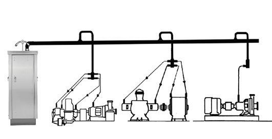
As early as 1965, oil mist lubrication proved by far the most successful lube application method on two 1,250hp vertical electric motors at a large refinery1. A recent book2 includes highly informative updates on this mature technology. Oil mist has been used by a bearing manufacturer since 1937 and by a textile machinery maker since the mid-1950s. By the early 1960s, oil mist had found its way into the process industries.
Why oil mist is mature technology
This gets back to an important point: oil mist lubrication should always be mentioned together with the additionally relevant topic of interest, oil mist preservation3. As is well known, oil mist fully preserves standby equipment and eliminates the mistakes often made with grease lubrication. The resulting reliability increase deserves to be reflected in the cost justification, as should failure avoidance and the ensuing reduction in pump related fires.
After oil and air are brought together at or near an ideal mixing temperature of 38°C (about 100°F) at a pressure of ~20 inches (~500mm) of H2O, the oil mist moves from this higher pressure to the much lower pressure (5-10mm of H2O) that
typically exists in a bearing housing. Once generated, oil mist will move in an unheated, uninsulated header and it will do so whether the external environment is at minus 45°C in Canada or plus 45°C somewhere in North Africa or the Middle East. Visualise oil mist to travel and behave like cigarette smoke. Today, every experienced user plant applies oil mist to both its pump and electric motor bearings4. Numerous papers and articles have documented oil mist preservation; an outdoor storage yard is shown in Figure 2. Finally, converting from grease to oil mist lubrication can be done with equipment running and is especially straightforward with electric motors5

A full 20 years ago, the CEO and majority shareholder of a prominent lubrication provider reported that plant-wide oil mist lubrication had been applied in over 100 refineries and chemical plants in dozens of different countries.
1 Miannay, Charles R, ‘Improve Bearing Life’, Hydrocarbon Processing, May 1974
2Bloch, Heinz P, F.K. Geitner, and D.C. Ehlert, ‘Optimized Equipment Lubrication, Oil Mist Technology, and Storage Preservation’, (Dec 2019), Reliabilityweb, Ft. Myers, FL
3 ibid
4 Bloch, Heinz P, ‘Dry Sump Oil Mist Lubrication for Electric Motors’, Hydrocarbon Processing, March 1977
5 Bloch, Heinz P, Improving Machinery Reliability, 3rd Ed. 1998, Gulf Publishing Company, Houston, TX
Although we are still not permitted to publish the names and locations of plants that supplied relevant data, we can share the benefits calculated by some of these oil mist users. It should be noted that these data include numbers one can use in calculating cost justification and payback. Moreover, satisfied users included major multinational companies, as well as small facilities. The investment made by these plants generated attractive returns and short payback periods based on improved equipment reliability and reduced maintenance cost.
The known areas of improvement with pure oil mist lubrication include:
1. Reduced pump and electric motor bearing failures:
• 80 to 90 per cent reduction in pump bearing failures is typical
• Electric motor bearing failures are often lowered by over 90 per cent
• Competent oil mist suppliers can provide data on:
a. Bearing failures at a major refinery in Thailand
b. A California refinery sharing its electric motor failure history
c. Bearing failure histories at a major olefins plant
2. Reduced number of mechanical seal failure events
• Reduction of seal failures is in the range of 30 to 50 per cent
• One user reported that the average mechanical seal life doubled to eight years
• Examples included:
a. Bearing and seal experience of an oil mist user in California
b. Seal life comparison from an offshore facility
3. Reduced failures rates of specialty equipment:
• Oil mist application has shown excellent results in a variety of other equipment applications
• Rotary lobe blowers, chemical mixers and cooling tower fan gearboxes are examples of more specialised applications with big payouts
• Examples include:
a. Polymer processing equipment failure history
b. Applicable experience with rotary blowers
c. Highly favorable refinery cooling tower gearbox history
4. Results expressed as mean time between repairs/failures (MTBR/MTBF), significant improvement for pumps, drivers and other equipment:
• One user reports improvement from three years before oil mist to nine years after oil mist
• Another user went from four years before oil mist to almost eight years after oil mist was introduced
• Detailed examples are available for:
a. A refinery in a Pacific Rim country that published seal life comparisons and highlighted how bearing issues lead to seal failures
b. Highly favorable pump MTBR experience
c. Similar favorable small steam turbine MTBR experience
5. Disclosure of pump maintenance costs, showing significant reductions. Percentages are given; for example:
• One user reports a 40 per cent reduction in all work orders for pump maintenance
• Others reported pump repair costs reduced by 60 to 80 per cent. These included:
a. An asphalt plant in the United States
b. Experiences at several refineries
c. Dollar cost reduction numbers provided by one refinery
6. Operations manpower to carry out lubrication tasks was reduced. Examples include:
• A user reporting a 47 per cent reduction in hours needed to complete lubrication related tasks
• User feedback from a Pacific Rim country supported the data
7. Lubricant consumption was reduced:
• A 40 per cent typical reduction due to more efficient application of lubricant
• One user reduced consumption by 70 per cent by applying recommended oil recovery steps
• A comparison of oil usage in several affiliated Pacific refineries is available
8. Reduced energy consumption is a fact:
a. At a minimum, a one to two per cent lower energy use was demonstrated in several controlled tests. Some tests by a major bearing manufacturer demonstrated a three and six tenths per cent efficiency gain
b. A South American energy consumption study has been published
9. Eliminated lost production incidents:
a. A specialty polymer producer estimated a seven to eight per cent run time improvement
b. A refiner eliminated costs from lost production incidents on a crude oil unit
The overall economic results from five refining applications have been published. The results are:
A. Western United States Refinery:
a. Applied oil mist to crude unit, fluid catalytic cracking unit (FCCUs) and steam boiler area in 1999
b. Experienced sharp reduction in pump maintenance costs
c. Eliminated lost production incidents on crude unit
d. Discounted cash flow (DCF) returns exceed 200 per cent
e. Payback achieved in less than one year
B. United States Southern Great Plains State Asphalt Plant:
a. One system serving entire plant was installed in 1997
b. Pump repair costs dropped 72 per cent
c. DCF return of 150 per cent
d. Payback in less than one year
C. Overseas Refinery:
a. Installed systems throughout one plant in mid-1990s
b. Compared performance with sister plant without oil mist
c. Results include doubling of MTBR for pumps and seals, cutting operating manpower in half, and reducing lubricant consumption
d. Estimated DCF return for converting the other refinery to oil mist is 54 per cent
e. Estimated payback is only 1.9 years
D. Mid-Coast Refinery:
a. Two systems installed in 1996 in crude processing units
b. Pump bearing repair costs dropped 88 per cent
c. DCF return of 70 per cent based only on lower repair costs
d. Payback was achieved in 1.5 years
E. Southern United States Refinery:
a. Three systems installed in 1989
b. Pump repair costs reduced by 65 to 70 per cent
c. DCF returns of 75 per cent achieved, based only on pump repair savings
d. Payback in 1.5 years
Similarly, the overall economic results for three petrochemical applications were made available in 1998. They showed the following results:
A. Specialty Polymer Plant in a US Western State:
a. Failure rate on rotating equipment was about every six months before oil mist

b. Failure rate dropped 98 percent after mist applied
c. Plant availability to manufacture polymer increased five to seven per cent
d. DCF return without including increased production exceeded 400 per cent
e. Payback was achieved in less than six months
B. Commodity Polymer Plant in US Mid-South Region:
a. High rate of rotary lobe blower failures prompted oil mist investment
b. Blower maintenance costs reduced by 90 per cent within two years
c. Resulting DCF return of 45 per cent and a payback period of two years
C. Central US Gulf Coast Olefins Plant:
a. Compared pump failures between a plant built in early 1980s with oil mist versus one built ten years earlier using conventional lubrication
b. Pump bearing failures were 90 per cent lower in oil mist lubricated plant
c. DCF return based only on lower bearing failures is 75 per cent
d. Incremental cost of oil mist implementation yielded payback in 1.5 years
In early 2005, a Saudi Arabian refinery reported accurate tracking of 1,400 process pumps lubricated by pure oil mist. In the previous year, there were no bearing failures in these pumps. The results coincided with those of other companies in the two decades before 2005: oil mist is a safe, environmentally friendly and technically sound lubrication method. Its reliability is unsurpassed and the resulting maintenance cost reductions and downtime avoidance savings have, for decades, been enjoyed by best in class performers in the United States and overseas.
Two separate updates on oil mist technology, occurring between November 2018 and March 2019 are worth mentioning. The first one came from a well-respected reliability engineer who was mystified when a new project did not include oil mist lubrication for a new process unit at his plant location. The unit was expected to be highly reliable and had been approved by the corporation’s board of directors based on several claims, among them, the claim of having been designed to minimise maintenance. The senior reliability professional at the plant receiving the project wrote:
“The issue of optimised lubrication comes up whenever our world scale oil refinery engages in plans for expanding throughput in process units or becomes the licensor for some of its process technologies. As a matter of custom and experience, the choice of properly designed and installed oil mist is not an issue with this refinery. The latest unit commissioned at our refinery, circa 2001, has had all its pumps running on oil mist for 14 years and has not had a pump out for bearing maintenance. This is, so far, an infinite MTBR (mean time between repairs). The process is relatively clean gasoline products and our pumps were properly sized for the various services. Sister units using oil mist have had a similarly long MTBR. Operations teams and reliability groups believe in the results achieved with oil mist, along with proper sizing and proper installation of process pumps. The statistical evidence is very supportive of the choices made since the early 1970s when oil mist was first tried in this facility.
“Regrettably, we still run into disagreement with an obviously contrarian corporate philosophy. We know that this disagreement originates with a perpetually unconvinced or probably not convincible subject matter expert (SME) far from our shores. This SME simply does not see the benefits of oil

mist that we have experienced and have understood for years. Our refinery is completely sold on oil mist and firmly advocates its use.”
Another update reads as follows:
“Our pump MTBR right now is somewhere between 114 and 120 months, depending on a lot of things, but we consider these numbers close enough. In any event, we still have not had a lubrication-related bearing failure since 1999 that's worth mentioning. Note that as of 2018 we have ACHE (air-cooled heat exchanger) fan bearings that have not been touched since the fans were installed in 2004. Moreover, the same impeccable results were obtained with the pillow block bearings on the FD (forced draft) and ID (induced draft) fans at our refinery, which, as you know, is the largest on this continent.”

The above reflects solid professionalism. Indeed, most reliability professionals are motivated and determined to 'speak truth to power', as the saying goes. These fact-oriented professionals continue to bring solid information to their project leaders and managers as they strive towards becoming best in class. The SME mentioned above is an outlier and his motivations are unknown.
According to primary providers of plant-wide oil mist systems, only three shutdown incidents are known to have occurred on oil mist systems since 1982. An estimated 3,400 plant-wide systems have been in successful service since that time.
7
6
The first recorded systems interruption involving a modern plant-wide oil mist system occurred at a US Gulf Coast facility around 1982. At that time, a thorough analysis traced the failure to pipe shavings in the five-gallon capacity misting chamber reservoir. Ferrous debris became attached to a magnetic level switch, preventing it from activating a solenoid. Uninhibited solenoid movement would have allowed lubricant from a bulk oil holding tank to replenish the much smaller chamber reservoir. When the small reservoir was depleted, none of the connected equipment received oil mist. The bearings ran dry but did so without incident or bearing failure.
As an aside, the question on how long one can run standard bearings without lubrication was answered in the early to mid-1960s. It was then known that bearings coated with oil in horizontally installed shaft systems can operate for about eight hours after discontinuing oil mist flow.
Test results were reported and explained by Dow Chemical’s Allen Clapp, and Fred Wilcox6. Their test-based findings were again corroborated in full-fledged academic research conducted by Abdus Shamim in pursuit of a doctorate at Texas A&M University7
The observations by Clapp and Wilcox indicated that a small pool of oil will collect in the five to seven o’clock segment of the contoured raceway in a bearing’s outer ring. Oil mist lubricated pumps can safely stay in service for approximately eight hours before this small pool of oil is depleted. Given that there is ample supervisory instrumentation to indicate deviations, no modern oil mist system has ever encountered unavailability in excess of eight hours.
The second unavailability event developed at an oil refinery in Enid, Oklahoma, where a single oil mist console was serving two adjacent process units. When the process unit where the oil mist generator (OMG) was located had to be shut down in preparation for scheduled maintenance and repair downtime, the OMG valve was inadvertently shut. A day or so later, the adjoining process unit experienced a pump failure. It was immediately realised that there had been no oil mist supplied for at least 24 hours. The oil mist supply was then quickly restored, and no other bearing failures were experienced on any of the connected pumps. The cause of the failure was clearly human error; it could have been averted with a simple advisory note posted at the appropriate switch or valve.
A third incident report relates to a Texas Gulf Coast oil refinery where the owner-purchaser had opted not to include an automatic fill option on the OMG console. A manual reservoir refill line connected a bulk storage tank to the small, 10L oil reservoir located inside the main oil mist console.
An operator decided to crack open the needle valve in the refill line, expecting it to slowly maintain the oil level in the small reservoir.
After a while, the entire piping distribution system had filled with liquid oil and the liquid oil had, in fact, displaced the atomised oil mist. About 12 pump bearing housings and their respective motor driver bearings were affected. A lot of oil was wasted, but there were no equipment failures in this incident.
It’s very difficult to remove the human element from a plant. All the checklists, procedures, signal lights, bells, whistles, tablets and laptops are of no benefit if a person decides not to pay attention. But here is the good news: modern oil mist systems are provided with suitable supervisory instrumentation. As a result, there are no known reports of any system being disrupted for more than two hours in the years from 2000 to 2018.
In 1998, overall reliability and availability were calculated by various observers as 99.99962 per cent (lowest) and are currently thought to have reached 99.999997 per cent (highest). The various availabilities recorded and reported for plant-wide oil mist systems have never been approached by any other lubrication method.
Considering the aforementioned three incidents, one has to wonder what else could cause an oil mist unit or system to shut down. Well, running a forklift into the two-inch oil mist header would shut the system down. It’s a rather remote possibility, since such an incident has never been reported on any of the estimated 3,400 plant-wide oil mist systems now in service all over the world. But, if it did happen, it would take less than eight hours to repair a header. Weld repairs could be done on the damaged header and filling the header with nitrogen would not be required while doing the repair.
Since very little can shut down an oil mist system, the most profitable and reliable plants have found that installing backup systems is not cost justified. Nevertheless, some plants have occasionally asked oil mist suppliers to propose and provide 100 per cent redundancy. In those facilities, a backup or auxiliary oil mist system can be placed in operation on a moment’s notice. Complete switchover from the main unit to a full backup takes 30 to 60 seconds. The switchover procedure calls for a one-quarter turn of the handle of a ball valve. A two or three sentence procedure sheet is posted on the inside of the oil mist cabinet door. The sheet explains what to do in the highly unlikely event of such switchovers ever becoming necessary.
Heinz P. Bloch resides in Montgomery, Texas. His professional career commenced in 1962 and included long-term assignments as Exxon Chemical’s Regional Machinery Specialist for the United States. He has authored or co-written over 750 publications, among them 21 comprehensive books on practical machinery management, failure analysis, failure avoidance, compressors, steam turbines, pumps, oil mist lubrication and optimised lubrication for industry. Mr Bloch holds B.S. and M.S. degrees (cum laude) in Mechanical Engineering from the Newark College of Engineering and is a member of the college’s “NCE 100’s Anniversary Top 10.” He is an ASME Life Fellow and was awarded life-time registration as a Professional Engineer in New Jersey.


Since 2018, Santos has been undertaking an Australian-first project in the Cooper Basin in South Australia and Queensland to assess the viability of converting crude oil beam pumps to solar and battery power in an effort to reduce its greenhouse gas emissions from oil and gas production. Following a successful pilot, the company has started rolling out the technology with the aim to install it at over 200 sites.
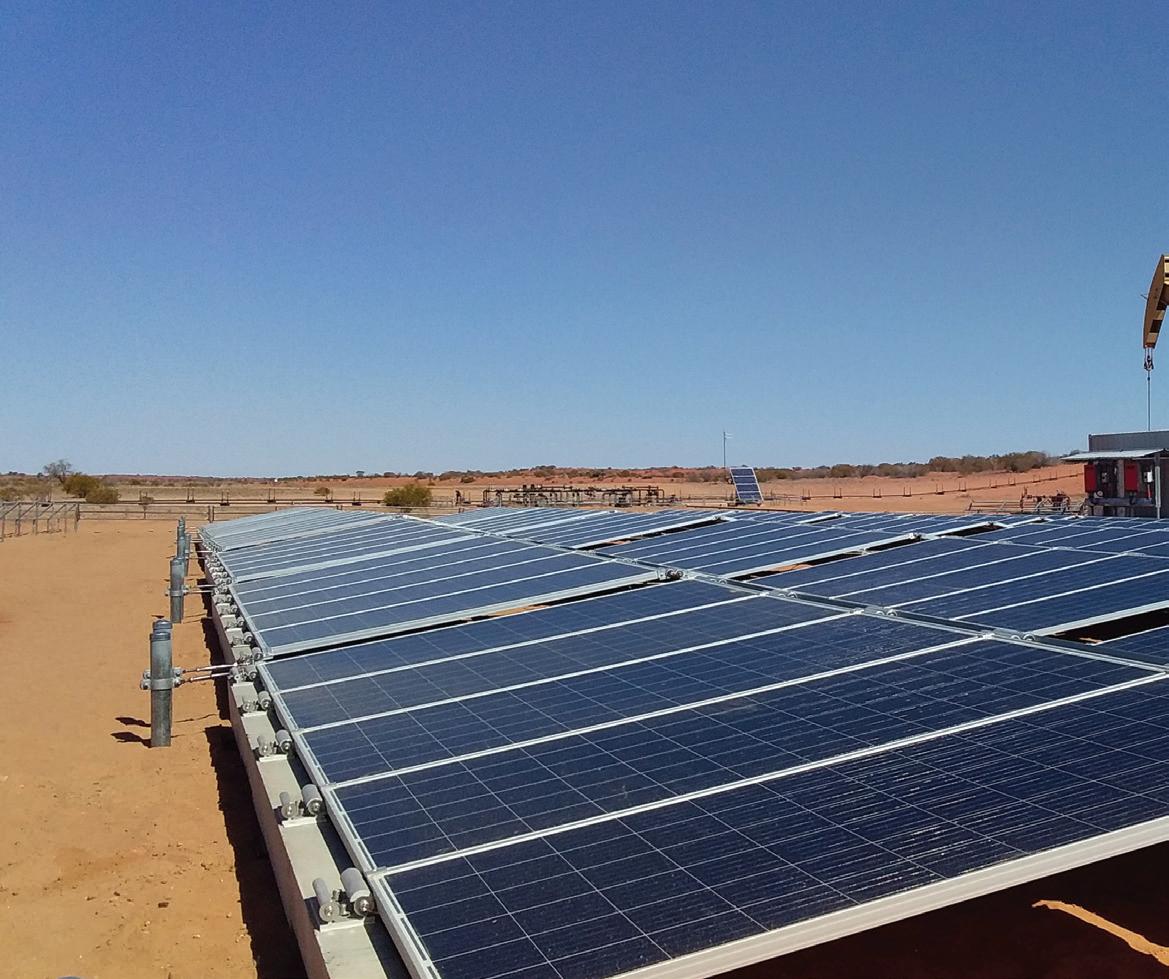


Santos has established a dedicated Energy Solutions team to drive energy efficiency and emissions reductions across the business, with this project one of the initiatives that aims to support the company’s target to reduce its emissions across the Cooper Basin and Queensland by five per cent by 2025. There are over 200 existing beam pumps across the Cooper Basin that could be converted and Santos aims to use solar power as the standard energy source for new onshore oil wells. By converting the beam pumps from crude oil to 100 per cent renewable power, it is expected to deliver environmental and commercial benefits by increasing system uptime and production, removing reliance on oil-fired generators which are not always reliable, reducing fuel usage, and reducing operational costs associated with maintenance and trucking of fuel.
The project will cost just over $16 million and received a grant of just over $4 million from the Australian Renewable Energy Agency’s Advancing Renewables Program, which supports a broad range of development, demonstration and pre-commercial deployment projects with the potential to provide affordable and reliable renewable energy in Australia.
The system uses high-efficiency ground-mounted solar panel arrays that are deployed on existing well pads. The DC electricity these arrays generate is then converted to AC via an inverter to drive the beam pump, with any excess power used to charge the batteries via an AC/DC inverter. When the beam pump load exceeds the PV generation, such as at night, the batteries discharge the stored energy via the inverters to power the pump.
A control system manages the charging/discharging of the batteries using remote monitoring and control that is carried out over Santos’ private LTE network.
Santos Managing Director and Chief Executive Officer, Kevin Gallagher, said, “This is a great example of renewable energy and battery storage working together to solve the problem of intermittency with solar and wind.”

There are a number of factors that need to be considered when designing and installing the system on any individual site.
As beam pumps have a cyclic load that varies with both the up and down stroke, as well as the speed of the pump – which is automatically optimised by variable speed drives to maximise oil production, and may vary with the life of the well – a key design consideration is the sizing of the units to meet the load demand.
Other considerations include the layout of the arrays onsite to allow for ongoing access to the well head for both daily operations and maintenance such as workover rigs to repair downhole pumps.
Santos plans to commercialise this technology through supply chain and execution synergies that come with scale.
From trial to rollout
A pilot has been running at Limestone Creek in South Australia since August 2018, using solar PV and batteries to power the beam pump that brings oil to the surface from deep underground reservoirs.
Mr Gallagher said the pilot had proven that solar PV and batteries can maintain reliability and availability in the harsh, off-grid environment of the Cooper Basin.
“This nation-leading project is good for the environment, it’s good for reducing fuel consumption and it is good for the bottom line,” Mr Gallagher said.
“This was Australia’s first oil well running on solar and battery, and following the success of the pilot, Santos has converted 23 more wells to solar in 2019, with a further 34 conversions planned this year.”
However, Mr Gallagher said that the project had not been without its challenges, but the company was learning how to overcome these.
“The remote nature of the project provides many logistical challenges including the delivery of goods to site and site installations,” Mr Gallagher said.
“With more than 20 solar beam pumps now installed, we are learning all the time and we are looking forward to the next 34 being installed throughout the course of this year.”
The COVID-19 pandemic has also presented challenges for the project.
“Just like all aspects of the Santos business, we have put in place robust protection measures so that we can keep production going safely during the COVID-19 restrictions,” Mr Gallagher said.
“That means our installation timelines remain on track despite all of the challenges COVID-19 has presented.”
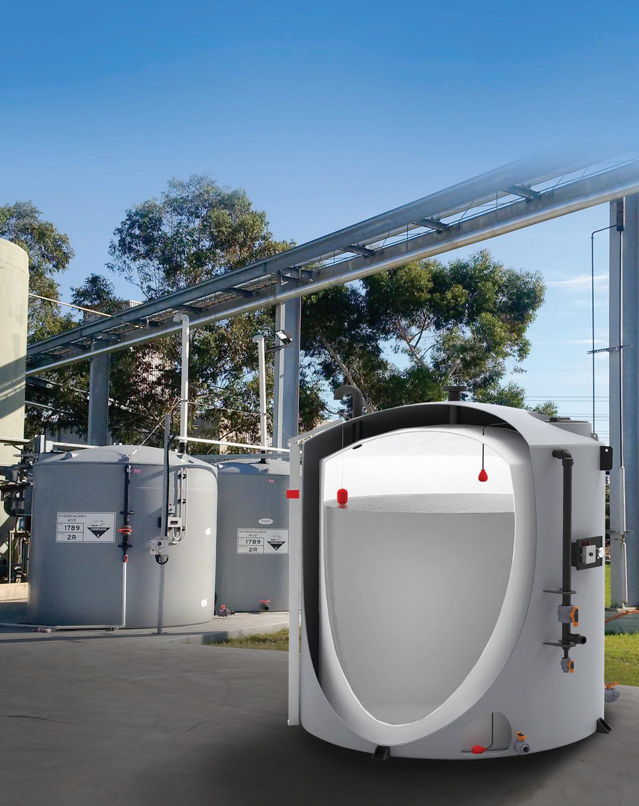

Pumps, pipelines and fittings can get seriously damaged if pressure or flow are out of control and occurrences are not tracked early.
The Pump Genius is a customisable feature in WEG drives that enables your standard VSD to become dedicated for pumping systems. It ensures accurate pressure/flow control throughout the processing cycle, starting with raw water and its usage, through to wastewater treatment.
With an easy-to-use programming wizard, Pump Genius helps you to minimise downtime and maximise energy savings. All you need to do is to select one of the three options that best fits your application.
simplex
The Simplex software adds ideal features to the VSD for single pump control.
• Pipe Charging Mode
• Sleep & Wake-Up Modes
• Dry Pump Protection
• Broken Pipe or Leakage Detection
• Pump Cavitation Monitoring
multipump
Multipump is the best choice when a pumping system needs to be integrated with a cost-effective solution. It enables one single VSD to control up to five pumps via DOL, soft starter or other starting methods.

multiplex
Multiplex software is the most complete solution to accurately control flow and pressure with high reliability. The VSDs control, monitor and manage the entire system on their own. There is no need for additional PLC, HMI or any external devices thus installation costs can be optimised.
WEG has launched Pump Genius process control software which enables engineers to optimise their pumping systems, so they run more efficiently. The software is designed to reduce pumping system operation and maintenance costs while increasing process accuracy and protection.
The software works with WEG’s popular CFW11 drive to control system processes easily, providing multiple pump control and protection, as well as system monitoring. Pump Genius can be applied to any system that requires constant flow or pressure, and can manage and monitor up to six pumps in a coordinated system.
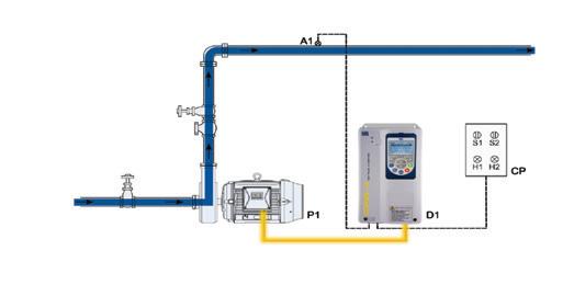



Essentially developed for pumping systems, Pump Genius is a customizable function of the WEG drives, which makes the frequency inverter suitable for this type of application, ensuring precise control of pressure and flow throughout the entire processing cycle. With an easy-to-use programming assistant, Pump Genius helps to minimize maintenance time and maximize energy savings. From water abstraction to waste treatment, Pump Genius is the customizable WEG solution for maximum efficiency.

Shoalhaven Water (SW) is now concluding a three-year multi-generational leap in its remote telemetry systems. SW had identified the need to improve a number of areas within its current organisation-wide Supervisory Control and Data Acquisition (SCADA) system including the data analytics capability to provide better intelligence for its business. The gaps in the capabilities and features of the current SCADA system stem from the following main issues: by the very nature of the older technologies, there are limitations in the features of the existing analogue radio system and legacy telemetry units to support more sophisticated data diagnostics, and time and date information required to facilitate data analysis. With minimal ongoing annual capital works funding on SCADA enhancements the current system has fallen significantly behind state of the art. Hence, the objectives of this project are to address the gaps in the capabilities and features of the current SCADA system as described above through the following upgrade works: enhancements to the current ClearSCADA applications software configuration, upgrade of the data communications network from analogue to digital, and implementation of new digital RTUs at all remote sites. This article details the steps taken to achieve cutover of such a significant portion of remote sites in the first year of a major capital works project; the experiences learned along the way; as well as presenting some state-of-the-art SCADA displays, reporting and IoT systems integration.

Introduction
Shoalhaven Water (SW) is a large regional utility on the New South Wales south coast. Tied to Shoalhaven City Council, the approximate 5,000km2 coverage area consists of many satellite wastewater schemes as well as delivery of potable water from two large water treatment plants (WTPs) in both the north and south.
The water system consists of five dams, four WTPs, and numerous water reservoirs, water pumping stations (WPS), valves and other dosing systems – treating and distributing approximately 45ML of potable water per day.
The wastewater system consists of 13 wastewater treatment plants (WWTPs), 220 sewer pumping stations (SPSs), numerous valves and other dosing systems to collect and treat approximately 18ML of wastewater per day.
All of these assets are monitored through SW’s SCADA system and have been for some time. With the recent wave of Internet of Things (IoT), the 1,100 low pressure pumping units (LPPUs) within the wastewater network are progressively being retrofitted with low-cost sensors for inclusion onto the existing SCADA system for exception reporting and alarming.
Historically, SW has operated on a Radtel-based SCADA system with a mix of 3000/5000/8000-series RTUs communicating over an analogue radio network. With these RTUs now unsupported and well past their end-of-life, a major push for a digital telemetry and SCADA upgrade was initiated in 2015. Through extensive expressions of interest (EOI) and request for tender (RFT) processes, three tender packages were awarded late in 2017, with the major rollout commencing in January 2018.
In the first year of the upgrade project, over 60 per cent of sites were cutover to the new digital telemetry system, and now 2.5 years into the three year project, 98 per cent of the
approximately 350 remote sites have been upgraded with the remainder scheduled for upgrade in the coming months. This has been supplemented by state-of-the-art ClearSCADA software and reporting enhancements; significantly improving day to day operations for field staff, emergency response, as well as management decision-making and forecasting system-wide.
This exceptional rollout pace has been thanks to a committed project team; consisting of both internal SW staff, and partnerships with key external contractors; SAFEgroup Automation and Downer EDI, for both hardware supply and installations, as well as SCADA system integration.
A 20+ year old telemetry system has its drawbacks, although for SW and many other water utilities, in its day, the RadtelSCADA telemetry systems very well served their purpose.
However, over the years and turnover of staff in both management and field, and SCADA services and water/ wastewater operations as a whole, what started as standards slowly, over time, became not-so.
For SW specifically, the siloed schemes allowed staff to request their own means of displays, reporting methods and alarming protocols. To the point where maintenance between the 13 databases ceased. Subsequently when staff from opposing schemes were scheduled for on-call duties, responses to problem situations would vary from site to site, scheme to scheme.
The last telemetry upgrade project in 2012 conducted extensive consultation with mainly field staff, where the majority wanted “the same look and feel” of the existing system. As such, this upgrade was purely a conversion from
By Adam Drenoyanis, Unit Manager – Digital Control Systems, Shoalhaven Water
RadtelSCADA to ClearSCADA, reproducing the same screens without any rejuvenating of SCADA mimics or reporting functionality. Significant money was spent for no real improvements.

This current upgrade has been driven from management, after external consultants provided a 30-year asset assessment and upgrade forward plan based on the data extracted from the SCADA system above. Due to the inaccuracy of these records, most sites had over one million data points, when even filtered down to a usable 100 thousand points have proven to be a significant overshoot. This has led to inaccuracies in asset life and system capacity predictions, where some major capital works projects could have been delayed for extended periods and thus decreasing costs.
Where to from here?
An EOI process was advertised in 2015, whereby the SW SCADA team went out to the industry to ask questions and test the market. This became quite a long internal review process, though it enabled SW to trial a number of digital telemetry solutions throughout. A comparison between a polled RTU analogue point (red) and the same analogue as a buffered SCADApack 334E point (blue) in Figure 2 shows a distinct difference in data integrity.
Learning a lot along the way, SW was able to clearly define where it wanted to go for the future. Then, in 2017, some two years after the EOI was advertised, SW was ready to advertise RFTs. Clear decisions were made on the arrangement of these tenders, splitting the project into three separate tender packages:
• Package 1: SCADA software enhancements/System integration (SAFEGroup Automation)
• Package 2: Supply of Hardware (SAFEgroup Automation)
• Package 3: Installation of Hardware (Downer EDI)
This arrangement allowed SW to
be risk averse, and award successful tenderers best-fit to each of the package’s defined scope.
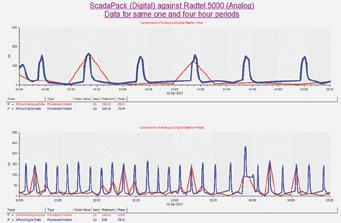
Working closely with SAFEgroup Automation system integrators (SIs), a clear plan was defined for a quick delivery of remote sites in both telemetry hardware and SCADA software enhancements. Beginning with the wastewater section first, the integral part of this was to develop a new standard SPS code and mimic, covering as many remote sites with a single template as possible.
With the above, and some other valuable tools developed by SAFEgroup Automation, configuring new telemetry hardware in preparation for installations was significantly streamlined. And, with a steady stream of fully-built RTU panels being ordered, delivered and installed, SW had successfully cutover 210 SPSs, four WWTPs, 228 LPPUs and a number of water assets in the first year of the three-year project, well over 60 per cent of telemetry sites.
The new telemetry station pages offer significantly more information on a single display, eliminating the previous requirement to jump from page to page just to trace back history, reports and events. Compared to that shown in Figure 1, the move to more abnormal situation management (ASM)-inspired standard displays, as shown in Figure 3 below, has improved staff response to critical events and allows clear alerts to any states out of the ordinary.

More focused on the scheme-based overviews, the upgrade to ClearSCADA 2017 software has enabled the inclusion of map-based geographic displays. This, in turn, provides the ability to overlay web-based map service layers such as internal GIS layers and Bureau of Meteorology data feeds. This functionality has allowed vastly improved management of emergency response. These are shown in figures 4 and 5 below respectively.
Furthermore, utilising fixed radar level sensors in SPS, and continued improvements in SCADA data collection and prediction has allowed for the plotting of standard, expected diurnal inflows at critical wastewater sites (Figure 6). This gives the ability to alarm in real time lower than (or greater than) expected flows at specific time-slices of a day, allowing early identification of potential problems upstream from the corresponding SPS site.


One of SAFEgroup Automation’s latest ClearSCADA features is a Microsoft Teams integration (Figure 7), which, in the current pandemic has been heavily


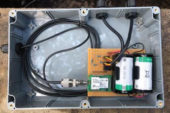

utilised to send daily data updates to management staff which do not require usual SCADA access from home.
SW began its IoT journey early in 2017, with a number of undergraduate engineers coming through since then focusing their university theses on IoT applications within the water/ wastewater networks. Over this time a significant network has been rolled out throughout the region (Figure 8). Not only servicing other parts of council for smart cities-type applications, SW has many devices in development for applications, including monitoring of gravity sewer manholes; digital and analog level indications; pressure reducing valves (PRVs) (Figures 9 and 10) and an Implementation of an IoT Based Radar Sensor Network for Wastewater Management1 paper.
This paper offers a complete review of wastewater monitoring networks and was one of the first to offer robust testing of Long Range Wide Area Network (LoRaWAN) network capabilities in Australia. The paper also provides a comprehensive summary of the LoRa protocol and all its functions.
It was found that a LPWAN, utilising the LoRaWAN protocol and deployed appropriately within a geographic area, can attain maximum transmission distances of 20km within an urban environment and up to 35km line of sight.
Additionally a second IoT network has been configured and deployed in the Kangaroo Valley and Lake Tabourie townships, with sensors developed in partnership with Ventia/Vianet to monitor the low-pressure sewer system (LPSS) pump network tied to each residence.
A low-cost retrofit solution was designed to supervise the previously unmonitored eOne LPSS (Figures 11 and 12). Response to issues with these systems has been historically reactive, rather than proactive, reliant on notification of the resident to the local visible and audible alarm. With the IoT devices in place it has permitted SW to transition to more of an ‘invisible’ utility – monitoring each LPSS pump alarms, runs, starts, runtimes and power consumption, allowing proactive attention to problem sites prior to residents becoming aware.
Large-scale deployment is complete, with over 700 of these devices installed
and a further 400 scheduled for the townships of Bendalong and Lake Conjola. The data collected from these devices has provided an excellent comparison between live 'standard' gravity sewer and low-pressure sewer systems.


This article has detailed the current SCADA upgrade currently nearing conclusion by Shoalhaven Water. From the historic system outlined above, to the improved system being delivered, the benefits are clear. These are not only from visual software enhancements, but also in the way data is collected from sites. The move from legacy analogbased protocols to DNP3 has enabled a vastly greater trust in the data produced by SW’s SCADA system.
Leading on from this and into ‘Industry 4.0’, SW now has the opportunity to create IoT-capable devices that offer freedom from the reliance on mobile network providers, whilst avoiding congestion on the existing SCADA telemetry backbone. This has allowed better-quality asset life forecasting as well as predictive alarming based on operationally historic trends.
SW would like to thank all who are currently involved in this upgrade project: both internal operations staff and key stakeholders who have provided support and guidance to allow this project to endure, as well as the external contractors from SAFEgroup Automation and Downer EDI who have kept up with a rapid rollout pace, allowing SW to remain ahead of schedule and under budget.

In this Queensland Farmers Federation case study, an Energy Savers audit for a pawpaw farm near Mareeba has proposed the site’s diesel irrigation pump be converted to solar, with an expected 100 per cent energy saving and an approximate five year payback period.
The farm, near Mareeba, grows pawpaw which is packed for the national market. Cattle are a secondary focus. Irrigation is mostly by drippers to the pawpaw trees, but there are plans to move to sprinklers in the future. Irrigation continues throughout the dry season for up to eight months per year depending on rainfall.
The farm operates a single diesel pump for irrigation, but future expansion is anticipated with a second pump site under development. These pump systems have been the focus of an energy efficiency audit.
Current energy demand
The site energy consumption consists of:
• One 36hp centrifugal pump that is belt-driven by a diesel engine used to draw water from the Tinaroo irrigation scheme
• Estimated future energy requirements for a new paddock and pump installation were estimated for auditing purposes
Action
An audit of site energy consumption evaluated a number of options, including:
• Diesel pump replacement
• Electric pump installation (requiring grid connection)
• Solar photovoltaic (PV) pump installation
Results
Each pump location (existing irrigation system and new planned irrigation system) was evaluated separately to identify the optimal solution and associated lifecycle costs.
The baseline case for both pump locations for evaluation purposes was an electric pump installation with grid connection. At the existing pump site, a new diesel powered
pump was also assessed for lifecycle comparison purposes due to the existing units remaining serviceable life.
At the existing pump location the recommendation is to install a solar powered 19kW electric pump with a 20kW solar array over an area of 150m². The estimated payback occurs around year five, with an electric grid-connected pump only marginally better than the replacement diesel pump over the 15 year lifecycle due to estimated network connection cost. Also, upgrading to a solar powered pump eliminates diesel consumption of 8,900 litres and the labour costs associated with ongoing refuelling and maintenance.
Similarly the new pump site recommendation is a solar powered 9.5kW electric pump with a 10kW solar array over an area of 75m² with the return on investment being immediate due to the estimated network connection cost of the electric pump similar to the solar PV arrangement.
Analysis of the energy consumption per ML of water pumped demonstrates energy used in a diesel pump is significantly higher than the energy consumption for an electric pump. This is because the typical efficiency of a diesel pump is in the order of 30 to 40 per cent, whereas electric centrifugal pumps have a typical efficiency of 70 to 80 per cent. For this farm the MJ/ML/m head reduced from 36 to 12 when adopting an electric pump over the diesel installation.
The owner has expressed interest in implementing the audit report recommendations, with timing to be confirmed.

This case study was originally published by Queensland Farmers Federation. To view more irrigation and energy saving case studies, visit www.qff.org.au/energysavers.
Pump cavitation is an insidious thing. A cavitating pump does not operate on its pump curve, it will not pass the desired flow rate, and is continually in the process of destroying itself. During my Piping System Fundamentals classes I always pose the question, “How do you know if a pump is cavitating?”. The typical response is “It sounds like it’s pumping gravel”.

YOU’LL BE SORRY IF YOUR PUMPS ARE CAVITATING ALWAYS LOOKINGBy Ray Hardee, P. E., Engineered Software

This is one way to determine if it’s cavitating, but by the time you hear it, the impeller is well on its way to the scrap heap. With all the pump damage cavitation causes, you would think there should be a better way. There is no such thing as a cavitation meter; the only way to tell is to calculate the Net Positive Suction Head available (NPSHa) at the pump suction. Once this is done, you need to compare it to the pump’s NPSH required (NPSHr) value supplied by the pump manufacturer. If the NPSHa at the pump suction is greater than the manufacturer's NPSHr for the flow rate, the pump is not cavitating.
If the NPSHa at the pump suction is equal to or less than the pump’s NPSHr value, the local pressure at the pump suction is lower than the fluid’s vapour pressure. When this occurs, some of the liquid at the pump suction turns to vapour forming small bubbles in the flow stream. The vapour bubbles in the flow stream take up more space than the process liquid; this causes the pump performance to change while it’s cavitating.
Following the flow of the liquid vapour mixture through the pump, as it passes into the eye of the rotating impeller the fluid pressure starts to increase. When the local pressure within the impeller increases above the fluids vapour pressure, the bubbles return to liquid. The small vapour bubbles violently collapse on the pump impeller, causing a loss of some of the impeller material. Over time the worn impeller will permanently affect the pump’s ability to operate on its curve.
As previously mentioned, when a pump is cavitating it is not operating on its pump curve. That difference in the pump curve is how the manufacturers determine the pump's NPSHr value. During the test, the pump is operated while the suction pressure is reduced. When the observed pump head drops by three per cent, the test standards define that as cavitation. The manufacturer then calculates the NPSH at the pump suction and lists that as the NPSHr value. If you look at the pump standards, the pump is already cavitating when the suction pressure is at the NPSHr value.
The only way to know if a pump is cavitating is to do the math. NPSH available is described in Formula 1. Figure 1 shows the location of each item in a system.
Equation 1
P = pressure
cf = unit conversion factor
ρ = fluid density
Z = elevation
h = head loss in suction pipe
Formula 1
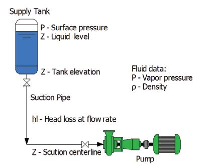
The NPSHa equation is made of three parts, the pressure, elevation, and losses in the pump suction pipeline. The first part deals with pressure consisting of the tank pressure plus the local atmospheric pressure minus the vapour pressure of the fluid. The pressure value is converted to head by dividing the conversion factor by the process fluid density.
The second part is based upon elevations, specifically the elevation of the tank, plus the liquid level in the tank, then subtracting the elevation of the pump suction nozzle. The third element is the head loss in the suction pipeline.
The second step is to go to the manufacturer’s supplied pump curve to determine its NPSHr for the flow rate.
Since the pump is cavitating when the NPSHa equals the NPSHr, it is good practice to include an NPSH margin ratio. A variety of standards are available to provide guidance based upon the pumping application.
The final step is to determine if the NPSHa is greater than the NPSHr multiplied by the NPSH margin ratio. If that’s the case the pump is not cavitating.
Note when looking at the NPSHa expression a variation in the suction tank level, pressure, or fluid density affects the pressure and elevation parts of the equation. The flow rate through the suction pipeline affects the head loss value as well.
I can hear you now
You’re probably saying, “I have a plant to run, I don’t have time to do all this”. The good news is that most piping systems typically don’t experience pump cavitation. That way you limit your search to pumping applications with low suction pressure, or pumping fluids with high vapour pressure, or with high flow rates.
When you’re looking for trouble you can develop a spreadsheet to help in performing the necessary calculations. More than likely, the most difficult task is to find the manufacturer’s supplied pump curve to determine the pump’s NPSHr value.
So the next time you think a pump is having a pump problem, you should perform your NPSH test. It’s a great way to look for trouble.
Ray T Hardee, PE, is the Chief Engineer and a principal founder of Engineered Software Inc., creators of PIPE-FLO® and PUMP-FLO® software. The PIPE-FLO product line helps some of the largest companies across a variety of industries find hidden profit in the design and operation of their fluid piping systems through simulation software, modelling services, and training opportunities. Hardee is a member of the Hydraulics Institute, ASME Energy Assessment for Pumping Systems standards committee and ISO Pumping System Energy Assessment committee. Ray’s publications include Piping System Fundamentals and contributions to HI’s Pump Life Cycle Cost and Optimizing Piping Systems. He can be reached at SimGuyRay@eng-software.com.


The key to successful, hassle free sump pumping is to eliminate priming issues.
Which is exactly how our ‘V’ Series Vertical shaft column pump works. Unlike a surface mounted unit, the ‘V’ Series is always primed as it’s submerged in the liquid, avoiding the need and expense of a suction line or foot valve and the NPSH restrictions associated with surface mounted pumps.
Its space saving design minimizes or eliminates floor space required for installation with the motor out of the liquid for easy maintenance and monitoring.
With the ability to pump water, suspended solids or semi viscous products and be used in high temperature applications and explosive atmospheres, the ‘V’ Series is also very versatile.
Save time, money and space up top, with an ASM ‘V’ Series pump down below. For more information contact ASM Pumps on (03) 9793 7577 or visit asmpumps.com.au

My original profession straight out of school was a Fitting and Turning Apprenticeship at David Mitchell Limited in Lilydale. I worked there for four years before floating between a few other jobs, mainly in the quarrying and mining sector. I started working afternoon shifts for Nubrik in Scoresby as a Maintenance Fitter. That was when the GST was first introduced, and they went from selling 1.9 million bricks a week down to about 80,000 bricks a week. As a result, there were voluntary redundancies of which I took one.
That’s when I got into the pump industry as a Service Fitter for Pump Engineers in Victoria. I moved into internal sales for a little while, then external sales before I moved on to a company called ATMR, which mainly focuses on the wastewater industry. They soon closed down in Victoria resulting in another redundancy for me.
Following that, I did a short stint as a subcontractor mainly working for Roger Withers at Regent Pumps. He was fantastic; he’d heard that I’d lost my job and he jumped on the phone pretty much straight away when he found out. He
was very clear that he wasn’t offering me a job, but he was happy for me to come into Regent Pumps and do a few things. So I did everything from production line to internal sales, and site work. Following him around the plant, watching Roger do what he did. He was fantastic, and helped me out over that period of time.
My next role was as the State Manager at Brown Brothers Engineers. I was there for five years. Within that role I also spent a little bit of time down in their Kelair branch, managing the sales team.
From there, I did a short stint at Franklin Electric, and then started at


David Lawrence has been working in the pump industry for almost 20 years. Since he entered the industry as a Service Fitter, he has worked for some of the biggest names in the Australian pump manufacturing industry and is currently a Sales Manager at Grundfos. Here, David talks about his career and the people he’s had a chance to learn from, the future of the industry and the challenges it holds, and working in the age of Coronavirus.
little gory, to an ice cream plant, which is clean, refrigerated and quite nice. So it’s always offered quite a diverse experience.
Sometimes you get to see things before they actually come out into the marketplace, with some experimental projects. The industry always seems to be at the forefront of a lot of technologies, from solar through to energy recovery and water treatment. There’s always something different happening, which keeps you interested and experiencing new things.
learning from others
The most memorable part of my career has been the people within the industry that I’ve managed to meet; some are great colleagues and some are now lifelong friends.
I like to think that everyone that you come in contact with is an opportunity for learning and for growth. I’ve found that most people that I’ve come across have helped me grow as a person, so I don’t necessarily look at it as any individual person who has been a mentor, everybody that I’ve come in contact over my career has taught me something.
I’ve been lucky across all of the companies that I’ve been to, there’s been some really good people within those businesses that have helped me along the way.
In my current role, Jamie Oliver, who was my segment manager when I first started and then Kevin Stiles, my current manager, Sam Ryder, and my Area Managing Director, Rick Holland, have all really been a great help. I’ve learnt a lot from them and they’ve all played pretty big roles in my recent career.
I think of the industry at the moment as being a little bit like the automotive industry of the ‘70s and ‘80s, where electronics and control is really starting to take over and dominate because we’re looking for efficiency, power savings and digitisation. People want to know what’s happening within their pumps, they want apps, they want visibility.
When you now go out to site to deal with a pump, you’re plugging laptops and connecting apps to the pump to diagnose what’s happening. Similar to the mechanic of the ‘70s and ‘80s when it went from carburettors and points and distributors to ECUs and fuel injection and
Grundfos where I’ve now been coming on six years. I’m currently the Victorian and Tasmanian Sales Manager for Grundfos Pumps, working on strategic plans for the business, mentoring and leading the sales team.
An industry with a lot to offer
The pump industry is a good industry to be in; it gives you a vast range of experiences.
Early in my career when I first started fixing pumps you got to see a lot of things that you probably wouldn’t normally, you’d be in an abattoir at some point, which is a bit smelly, hot and a


turbo charging. So our industry is really accelerating from that point.
Variable speed drives have been around for a long time, but now permanent magnet motors are starting to come into the mix. People are wanting to connect up to building management systems and they’re wanting to know what’s happening in their pumps in real time. They want to know when it’s going to fail and what’s the service interval. It’s certainly becoming more of a digital landscape than it is a mechanical landscape.
Some of the biggest challenges for us working in the industry is keeping up with this evolving technology. The skill set we need is changing so much. Traditionally you would be a mechanical engineer, or a fitter and turner like myself, but nowadays with the way things are heading more towards drives and controls, and internet platforms, we’re starting to see the need to understand more of the control side of things, similar to electrical engineers or electricians.
The industry is shifting away from being mechanical-based to becoming more of an electronic/electrical-based industry. So us as an industry, we need to be evolving too, and learning a lot of new skills to keep up with that.
Another challenge is the world is becoming more open and the buying habits of people are starting to change as well. From a selling point of view, you need to be evolving and the days of the account manager or sales rep with a briefcase driving around and visiting everyone is very different now. They don’t have as much spare time, so you’ve got to be very direct and efficient with the way you’re dealing with people. The way I was taught, and the way I used to sell back in my 20s compared to now, it has to be very different.
Information is a lot more available, so the client is not relying on your technical ability quite as much anymore. They can do the research online and find out what they think they need to know before you’ve even set foot in their business.
At this point in time it’s been a very reactive response to the circumstances, they’ve changed so rapidly and so frequently that it’s been very hard to keep up.
We’re very fortunate, being a big corporate business, that most of our systems and processes were online so we were able to transition from going into the office for work, to having to pack everything up and work from our homes in a very short timeframe.
From a supply chain, production, sales type perspective, we weren’t really impacted all that much. In fact, it’s almost business as usual for us. Just a little unusual that we’re all sitting at home, rather than being out and about.
The biggest adaptation has been the social interaction of staff, and the issues that come around from not having that social contact with each other. As a business, we’ve implemented a lot of virtual contact with each other – virtual coffee breaks, lunches, Friday drinks –to keep all of the staff engaged and in contact with each other. That seems to be working quite well.
We’re also making sure that we’re having phone calls with each other, we’re encouraging the teams to keep business as usual, and trying to keep in contact as much as we can.
Use the people around you. It’s a great industry, and it’s full of a lot of interesting characters and very knowledgeable people.
If you’re wanting to have a long career within the industry, you need to use the experience of the people that have been in it for a long time. It’s important to learn the fundamentals as well. I was very fortunate in my early years to work with two gentlemen by the name of Bill Williams and Bill Smith when I was at Pump Engineers. Their knowledge of the fundamentals of what we do as an industry was invaluable.
I think knowledge of some of the fundamentals is disappearing. For
example, affinity law viscosity corrections are now done by selection programs. I think the knowledge of how that’s calculated, why that’s calculated, and what the effects are of having to do those calculations has been lost a little bit.
I think that understanding the back end of what needs to be thought about when selecting a pump will really help you because it's so important to what we do.
Outside of thinking about pumps and pump related stuff, I’m obsessed with motorcycles. Every other moment from a hobby point of view revolves around motorcycles. I like to ride them – mainly Enduro style off-road motorcycling – and restore them. I’ve currently got a 1983 Yamaha RZ 250 road bike that I’m in the process of doing up.
My family is another really big part of my life. My wife, Monique, and my 14-year-old son, William. If I’m not playing with motorcycles or playing with pumps, I’m normally spending time with my family and going out for dinner, or going out for walks.
I love the outdoors, and we do a lot of that as a family; camping, bush walking, coffee, cake and food.


The pump industry relies on expertise from a large and varied range of specialists, from experts in particular pump types to those with an intimate understanding of pump reliability, and from researchers who delve into the particulars of pump curves to experts in pump efficiency. To draw upon the wealth of expert knowledge the Australian pump industry has to offer, Pump Industry has established a panel of experts to answer all your pumping questions.
This edition of Ask an Expert will look at the use of progressive cavity pumps in oil and gas applications, as well as special designs to comply with API standards.
Q: What makes progressive cavity pumps suitable for oil and gas applications and where are they most often utilised?
A: Progressive cavity (PC) pumps are positive displacement pumps that handle fluids gently and with minimal shear or turbulence. They convey abrasive fluids with the highest viscosity and solids content, even with large particles. They can generate high pressure (48 bar and more) and are suitable for high vapor pressure (low NPSH) and multiphase fluids.
In the oil and gas industry, PC pumps are often used to convey sludge or oily water, or in situations where light hydrocarbons raise the vapour pressure to a level where other pump types would cavitate. A forte of PC pumps is their vertical semisubmersed installation on a drum; open/closed drain drums or flare knock-out drums are a frequent application.
PC manufacturers offer a wide range of pumps for this industry from dosing and open hopper pumps to semi-submersible pumps or package solutions that allow for automatic control.

A semi-submersible pump that can be installed on a drum.
Q: How do these pumps meet the stringent requirements of American Petroleum Institute (API) 676 standards?
A: Historically PC pumps were primarily utilised in wastewater treatment plants; design and production were often optimised for this market. In comparison, the requirements of petrochemical applications are more demanding and are based on American standards.
Manufacturers regularly need to customise and upgrade their pumps for use in oil and gas, which dramatically increases costs and lead time. The most customisation is required for the casing design and shaft seals. Among other criteria, the casing design needs to have fully ASME compliant flanges, higher nozzle loads, flanged casing drain and a design pressure able to achieve higher containment pressure. Shaft seals also need to be engineered to meet API 682 requirements.
To provide project engineers with smooth sailing and purchasers with favourable prices and lead time, some PC manufacturers have designed and produced API 676

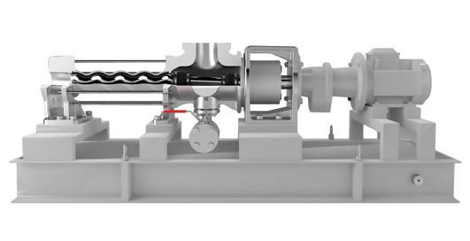
conforming pumps. They fulfill the casing and shaft seal requirements while being built with materials suitable for highly corrosive and harsh environments. PC manufactures use their many years of experience to create and produce solutions that help customers save time and money.
Peter Vila, Managing Director of SEEPEX Australia, is a progressive cavity pump expert. He has been involved with pumps for over 40 years. Peter spent the first five years repairing pumps and the following 35 years in technical sales, 20 of which have been with SEEPEX progressive cavity pumps.
For more information on progressive cavity pumps, please contact SEEPEX Australia on (02) 4355 4500 or at info.au@seepex.com


The PIA’s Australian Pump Technical Handbook is a cornerstone text for the Australian pump industry and, in our opinion, a must have for anyone who deals with pumps on a regular basis. In this ongoing series, we feature abridged chapters from the classic book to showcase the various areas covered and to reacquaint readers with the technical aspects of pumps. In this issue, we continue looking at energy efficiency in pumping systems, focusing on pump-system match.
One of the most important factors in achieving maximum overall system efficiency is ensuring pump capacity is matched to the system demand at any point in time so that the pump is operating at or close to its best efficiency point (BEP). This is particularly important for roto dynamic pumps, where the pump operating point will be determined by the intersection of the pump curve with the system curve.
In a simple system, where the design flow is constant, the system head varies
only a little due to minor changes in the static conditions. Here, pump selection is straightforward and the operating point should be easy to determine. By matching this operating point to fall close to the pump’s BEP, the lowest possible losses within the pump itself can be achieved. The only question might be whether or not the right pump for the job has been selected.
However, reference to the relationship between specific speed and pump efficiency may be able to find out the answer to this.
It is known that there are a number of operational advantages to selecting a pump that operates at or close to BEP, including:
• Low radial loads on the shaft
• Lowest losses within the pump due to hydraulic and mechanical losses
• Low vibration
• Low internal heat generation
These advantages all have a positive effect on the service life of the pump, particularly for bearing life, seal life, seal ring wear rates and clearances over time.
It is also important to understand the negative effects of operating away from pump BEP over time, including:
• Pumps operating at low flow conditions can display serious problems such as recirculation, vibration, overheating and potential component damage or failure
• Pumps operating on over-discharge can result in mechanical problems, and will require much greater Net Positive Suction Head required (NPSHR) to prevent cavitation
The question of whether or not the right pump has been selected is much harder to answer when the application requires the pump system to deal with a variety of demand conditions. In this situation, it is important for the user to understand the range of operating conditions that the pumping equipment must accommodate.
Changes in flow conditions can be accommodated by:
• Adjusting a control valve
• Changing the size of the pump in circuit
• Operating pumps in series or parallel
• Changing the speed of operation of the pump
• Combining a number of these options
It is important for the pump supplier to be provided with an accurate profile of the individual sets of operating conditions that the user needs to accommodate, so that the optimum combination can be determined. Having close cooperation between the end user and the pump supplier can play a significant role in achieving a ‘win-win’ outcome.
The pumping system can be adjusted to accommodate the conditions in the following conditions and ways:
• Routine low flow duties – these are often best achieved by using a small ‘jockey’ pump
• Flow demand has peaks and troughs – often best achieved by parallel pumps in circuit
• Flow demand has high variability – often best achieved by variable speed drives
The advantage of varying the speed of the pump to save power can be explained by the pump affinity laws –formulae that predict the impact of a change in rotational speed or impeller diameter on the head and flow produced by a pump and power demanded by a pump.
The formulae are as follows (for variation of speed with constant impeller diameter):
• Pump flow rate (Q) varies directly with the speed of (N) ie Q1/Q2 = N1/N2
• Pump head (H) varies with the square of the speed (N) ie H1/H2 =(N1/N2)²
• Power absorbed (P) varies with the cube of the speed (N) ie P1/P2 = (N1/N2)³
While these formulae assume that efficiency remains constant, in practice, efficiency is slightly lower at reduced speeds as friction and drag constitute a large proportion of hydraulic power.
From the discussion of piping system losses in part three of these articles, friction losses in a pumping system are proportional to the square of the fluid velocity decrease as flow decreases.
Therefore, at reduced flow rates, the pump will see a lower system head. A reduction in pump speed will provide the opportunity to match pump output to system parameters without throttling, which means a consequent loss of energy in the overall system is avoided. Application of this principle has resulted in the rapid uptake of variable frequency drives in pumping systems. If correctly controlled, the pump speed can be accurately matched to the flow demand, and the pump operates at or close to BEP. The effectiveness of this will depend on the control system design, which is often handled by a PLC controller to optimise the flexibility of the pumping equipment to match the various duties that need to be accommodated.
Further information and detailed diagrams, equations and schematics can be found in the Australian Pump Technical Handbook, available from the PIA website. In the next edition of Pump Industry, we continue to explore energy efficiency in pumping systems, looking at drivers and controls.

Specialising in custom design, manufacture, repair and service of centrifugal pumps for over 30 years
• Complete range of API 610 (ISO13709)
• Hydraulic and mechanical design
• Custom engineering, retro-fit, redesign
• Performance testing
• Service and repair
www.unitedpumps.com.au T: +61 3 9464 9500 31 Western Avenue, Sunshine Victoria 3020, Australia
E: unitedpumps@unitedpumps.com.au

Metering pumps are a positive displacement chemical dosing device with the ability to vary capacity manually or automatically as process conditions require. It features a high level of repetitive accuracy and is capable of pumping a wide range of chemicals including acids, bases, corrosive or viscous liquids, and slurries.
The pumping action is developed by a reciprocating piston, plunger or diaphragm which is either in direct contact with the process fluid or is shielded from the fluid by a diaphragm. Diaphragms may be activated by direct mechanical link or by hydraulic fluid.
Metering pumps are generally used in applications where one or more of the following conditions exist:
• Low flow rates are required
• High system pressure exists
• High accuracy feed rate is demanded
• Dosing is controlled by computer, microprocessor, DCS, PLC, or flow proportioning
• Corrosive, hazardous, or high temperature fluids are handled
• Viscous fluids or slurries need to be pumped METERING PUMP CHARACTERISTICS
1. The pumping action is developed by the reciprocating action. This reciprocating motion develops a flow sine wave. Actual flow rate is determined by the formula below in Figure 1.

2. Unlike centrifugal pumps, flow rate is not greatly affected by changes in discharge pressure (Figure 2).
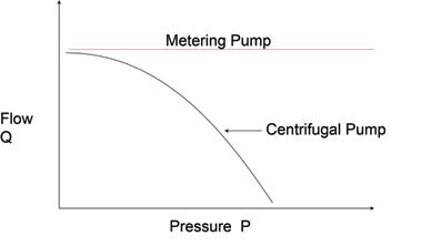
3. The metering pump flow vs stroke characteristic curve is linear (Figure 3). It is not however, necessarily proportional in that 50 per cent stroke setting may not equal 50 per cent flow. This is due to the fact that the calibration line may not pass through 0 on both axes simultaneously. By measuring flow at two stroke settings, plotting both points and drawing a straight line through them, other flow rates vs stroke can be accurately predicted.
The steady state accuracy of a correctly installed industrial grade metering pump is generally +/- 1.0 per cent or better. Although a metering pump can generally be adjusted to pump at any flow rate between 0 and its maximum capacity, its accuracy is measured over a range determined by the pump's turndown ratio. Most metering pumps have a turndown ratio of 10:1 which simply means that the pump is within its accuracy rating anywhere between ten per cent and 100 per cent of capacity. Some newer designs of metering pumps feature higher accuracy, and a greater turndown ratio of 100:1. Therefore, this design will accurately dose anywhere between one per cent and 100 per cent of capacity.

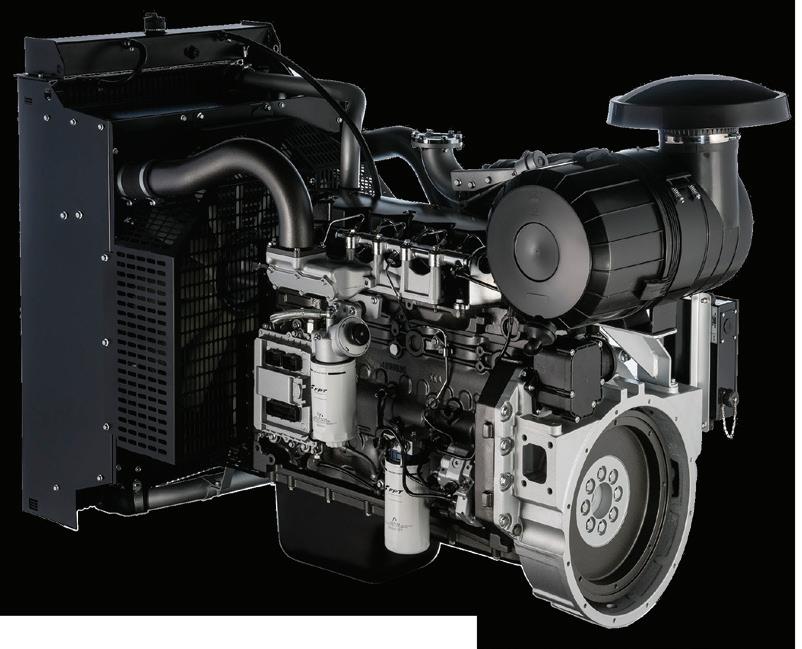


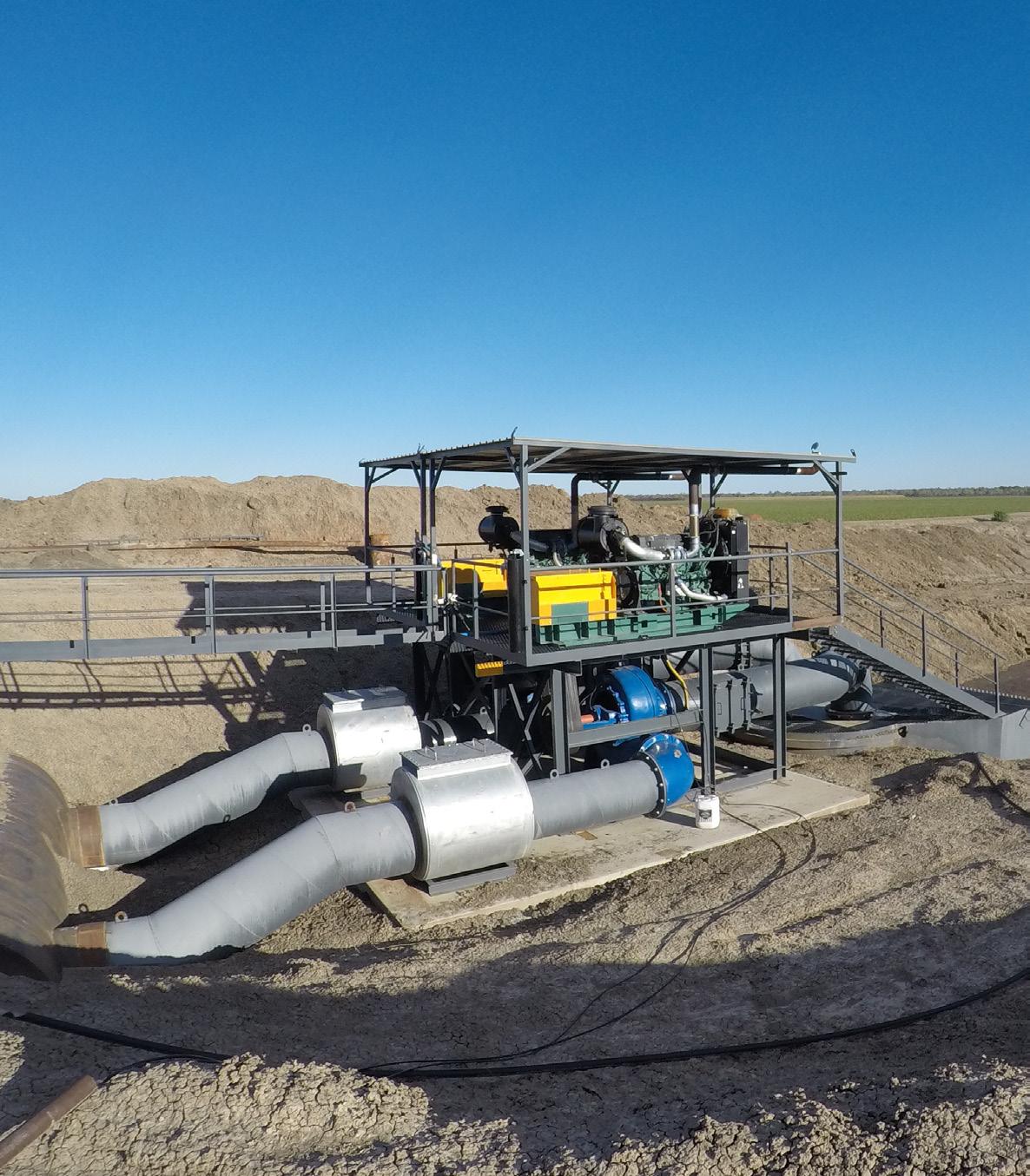

Volvo Penta. Robust, fuel efficient industrial diesel engines that keep running even in the toughest conditions. Easy to install, operate and maintain. A powerful partnership you can trust all the way from the drawing board throughout the operational life of your engine. Competitively priced complete power-pack units ready for delivery Australia wide with a local support team on hand 24/7. To find your nearest dealer visit www.volvopenta.com
