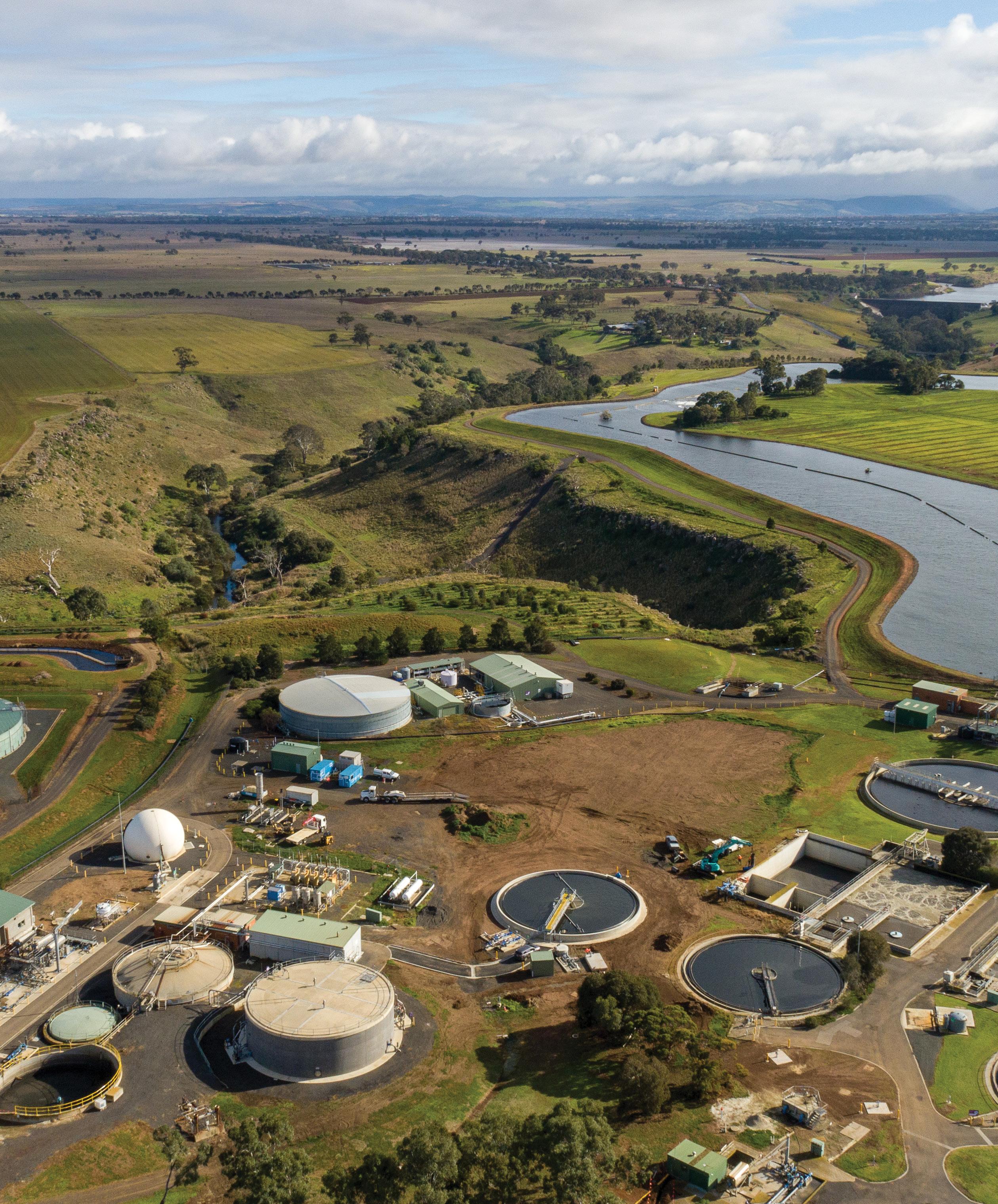

THE HIGH CAPACITY PUMP STATIONS powering
the WIN irrigation network
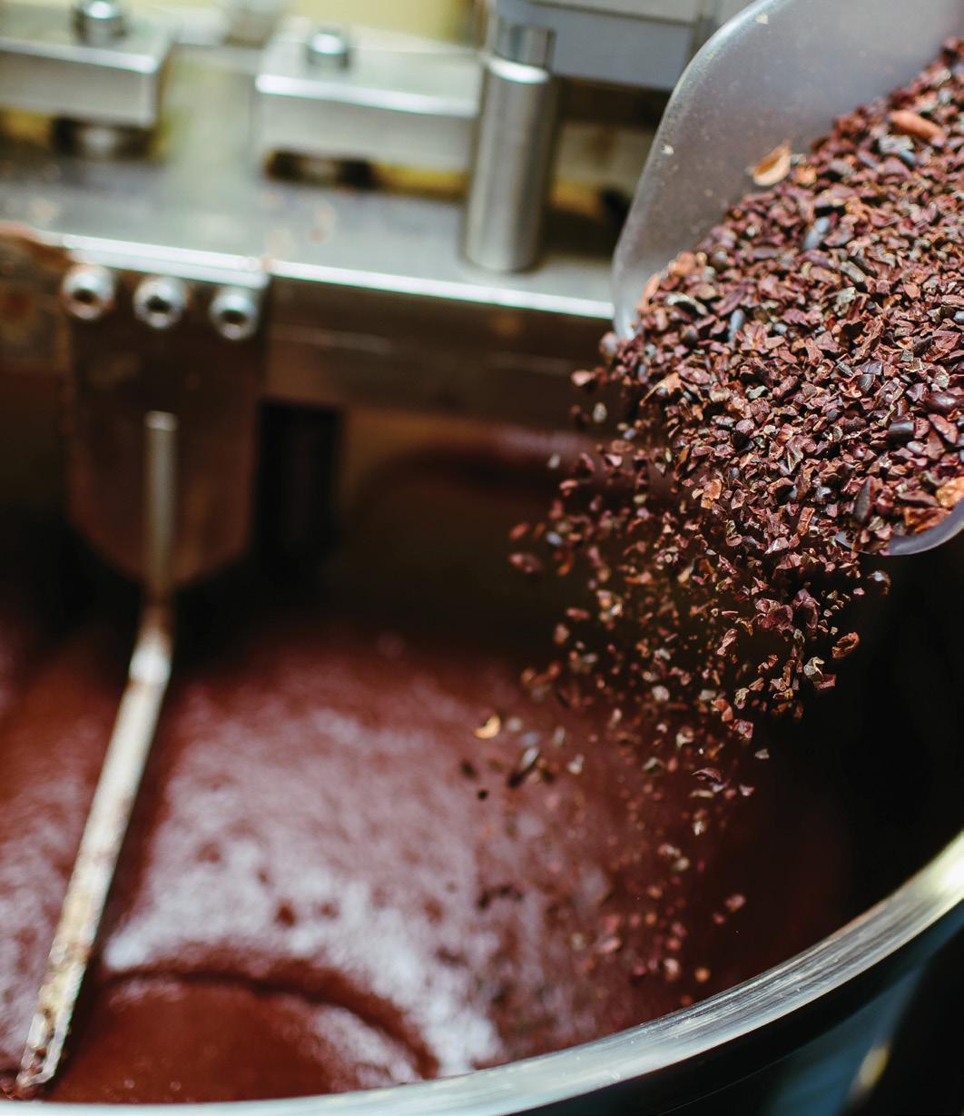
The bittersweet balance of CHOCOLATE PUMPS
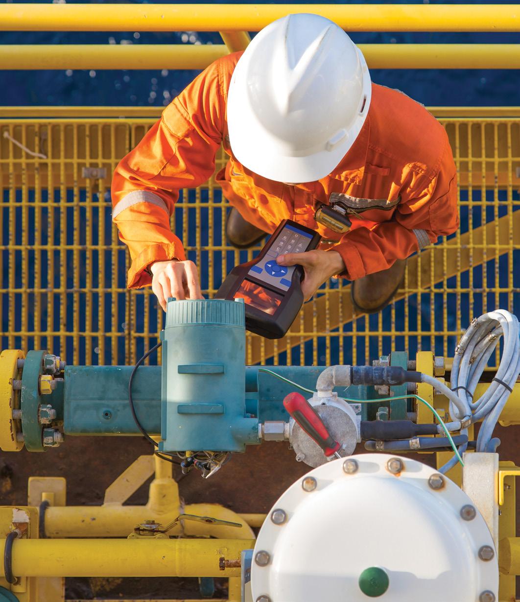
Considerations when selecting a flow meter

Bonfiglioli final drive, gearbox, geared motor or motion and control solutions are recognized in the market by worldwide leading players in the pump industry.
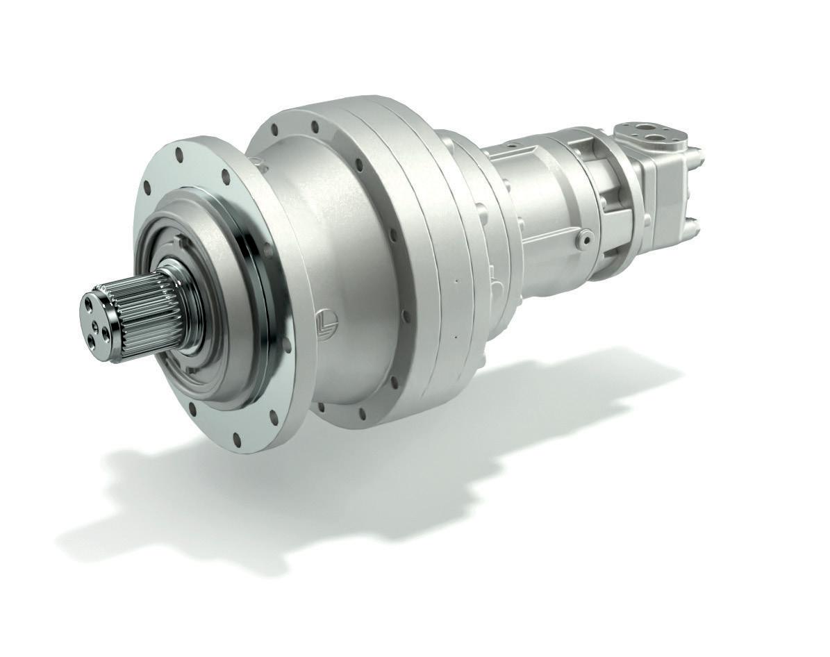
300M Series Planetary gearbox and geared motor
Benefits
• One-stop-shop for a complete drive solution
• High flexibility in layout and mounting positions
• High resistance in harsh conditions
• High torque density
• Wide range of working temperature working conditions
Features
• 20 gearbox sizes
• Nominal torque up to 1,300,000 Nm
• Modular design
• Increased bearing load capability
• Flange gearbox mounting
www.bonfiglioli.com/australia/en
A POWERFUL PARTNERSHIP

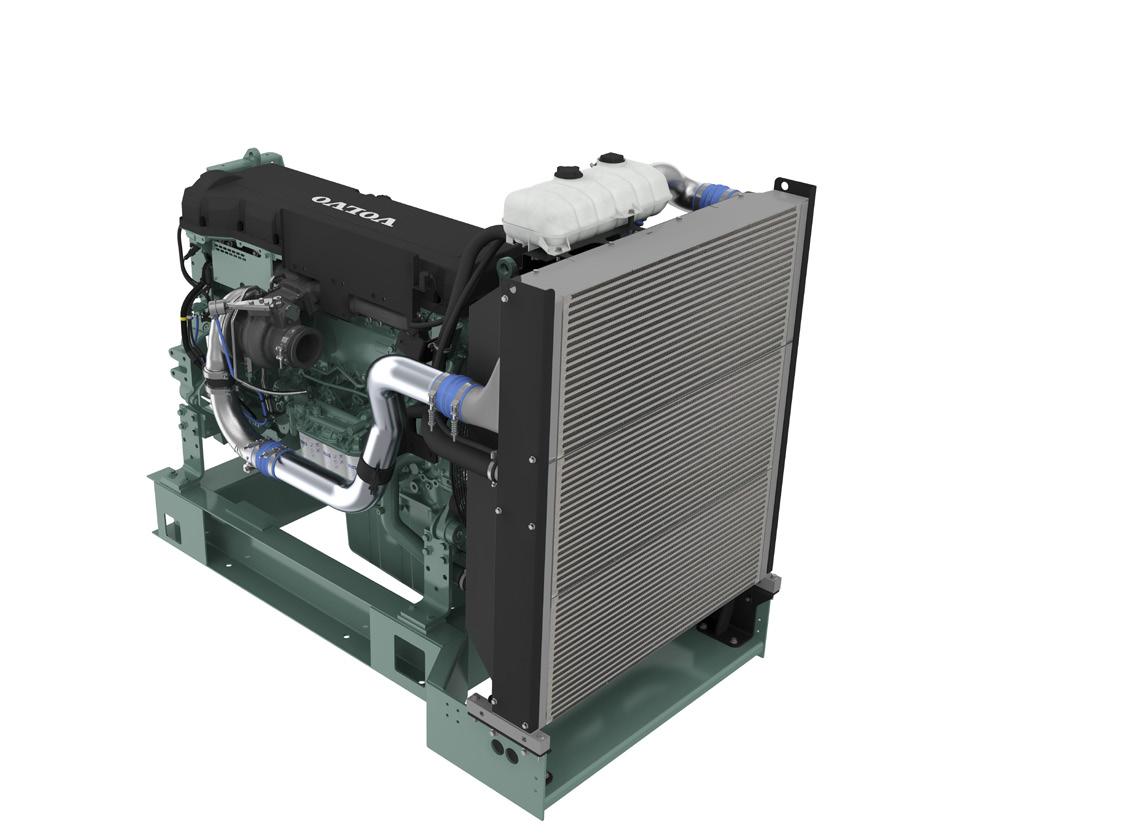
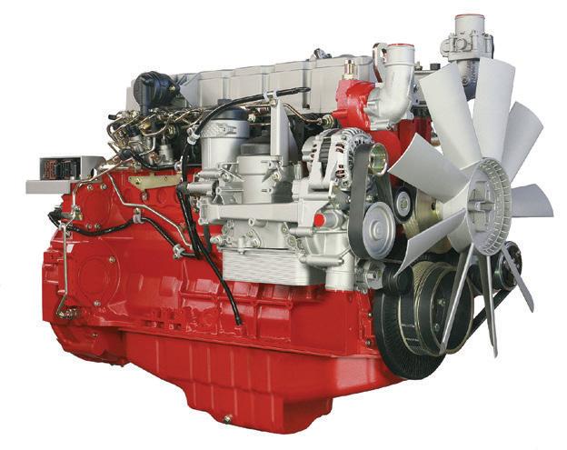
Volvo Penta. Robust, fuel efficient industrial diesel engines that keep running even in the toughest conditions. Easy to install, operate and maintain. A powerful partnership you can trust all the way from the drawing board throughout the operational life of your engine. Competitively priced complete power-pack units ready for delivery Australia wide with a local support team on hand 24/7. To find your nearest dealer visit www.volvopenta.com


President's Welcome
Hello all and welcome to the Winter Edition of Pump Industry Magazine. With the recent cold snap it certainly feels like winter has arrived with a vengeance, and plenty of snow to match. I understand here in Queensland it is the coldest start to winter since 1904 and similar statistics apply in other states.
Other face-to-face meetings are in the pipeline, with WEG Australia expressing interest to host an event.
Pump Industry Australia Incorporated
C/-340, Stuarts Point Road
Yarrahapinni NSW 2441 Australia
Ph/Fax: (02) 6569 0160 pumpsaustralia@bigpond.com www.pumps.org.au PIA Executive Council 2022
John Inkster – President Brown Brothers Engineers
James Blannin – Vice President Stevco Pumps & Seals
Kevin Wilson – Treasurer/Secretary Executive Officer
Alan Rowan – Councillor Executive Officer – Publications and Training, Life Member
Ken Kugler Executive Officer – Standards, Life Member
Michael Woolley – Councillor Tsurumi Australia
Geoff Harvey – Councillor Irrigation Australia Limited
Billie Tan – Councillor Regent Pumps
Steve Bosner – Councillor Pioneer Pumps
Joel Neideck – Councillor TDA Pumps
Mat Arnett – Councillor Ebara Pumps Australia
Jamie Oliver – Councillor Grundfos Pumps
Since our last edition we have seen a new Labor Government, which will have broad implications for business, particularly in the case of industrial relations, climate policy, and skills and training. On election night, the incoming Prime Minister said that his government would “work in the common interest with business and unions to drive productivity to lift wages and profits”. The IR agenda will be challenging with some policies already set in stone, like the abolition of the Building and Construction Commission (BCC).
On climate, Labor has said it will stay with the Paris target of reducing emissions to 43 per cent lower than 2005 levels by 2030.
But the honeymoon period, if there ever was one, was brought to an abrupt halt as the RBA turned up the heat with an aggressive 0.5 percentage point hike in June, taking the cash rate to 0.85 per cent with the warning there are more large interest rate hikes on the way. A bundle of fun for the new Treasurer as he grapples with higher prices for electricity and gas, and with inflation being much higher than expected now. Speaking with my colleagues in Europe, they expect a recession to occur, which would make it difficult for Australia not to follow.
At our last Council meeting we were able to report that we saw a late surge in registrations for the Seminar on “Pump Performance Monitoring” presented by Malcolm Robertson, making it very successful. We are currently looking at holding a seminar on Flow Meters, and an approach has been made to various manufacturers/suppliers on this topic where I am sure we will find some companies willing to participate.
But it seems this whole COVID thing is not going away any time soon; did you know that Australia’s COVID death toll in 2022 is more than double that of the previous two years. Federal health data shows 4,547 people have died of COVID-19 this year to date compared with 2,239 over 2020 and 2021 – a result of the high transmission of COVID in recent months, perhaps because of the relaxation of policies on face masks and social distancing sending a message to the general public that the pandemic is over.
Following the call received in March from a Senior Adviser in the Plumbing Drainage and Special Projects Division in the Department of Energy and Public Works regarding our request to the Service Trades Council (STC) to have suitably qualified PIA members undertake repairs and service of pumps as part of a plumbing or drainage system, there has been no further contact. The last meeting of the STC was set for late March so I cannot shed any further light on the subject, but I will follow up as I will with finding a spokesperson to conduct a Seminar on the Regulatory Compliance Mark (RCM). Ken Kugler, our Standards Officer, advises there is to be a review of AS2941; PIA will work in conjunction with Fire Protection Australia for this review. Also, Standards Australia is conducting a review of ISO2858-1975, ISO9905-1994 and ISO9908-1993. Ken has issued a request for industry input; this request is posted on the Home Page of the PIA website and is also being promoted in the Pump Industry newsletter published by Monkey Media. Responses are required by 31 July 2022.
As always, I wish you all a COVID-safe, flu-safe and prosperous year.
John Inkster - President
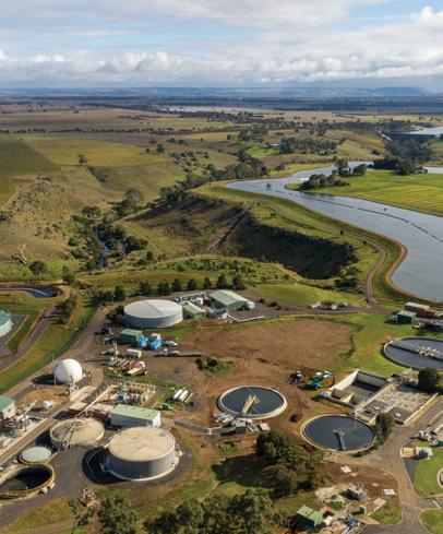
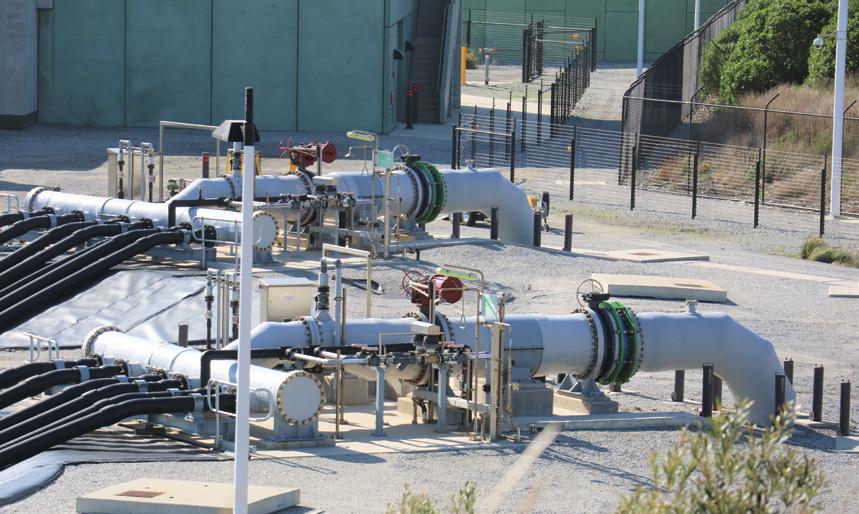
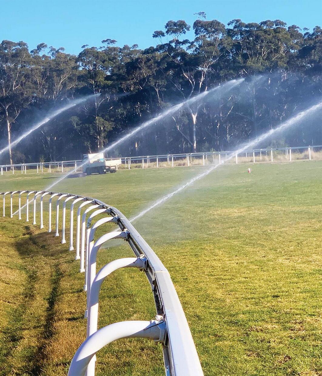
Cover image shows Greater Western Water's Western Irrigation Network (WIN), which includes three high capacity pump stations to deliver recycled water to farms in the Parwan-Balliang District.
Published by Monkey Media Enterprises
ABN: 36 426 734 954
C/- The Commons, 36-38 Gipps St, Collingwood VIC 3066
P: (03) 9988 4950
F: (03) 8456 6720 monkeymedia.com.au info@monkeymedia.com.au pumpindustry.com.au magazine@pumpindustry.com.au
Editor: Lauren Cella
Journalists: Lauren DeLorenzo
Business Development Managers: Rima Munafo, Jacob Trad
Design Manager: Alejandro Molano
Designers: Luke Martin, Danielle Harris, Jacqueline Buckmaster
Marketing Manager: Radhika Sud
Marketing Associate: Andie James
Digital Marketing Assistants: James Holgate, Jackson Barnes
Publisher: Chris Bland
Managing Editor: Laura Harvey

PIA MEMBER NEWS

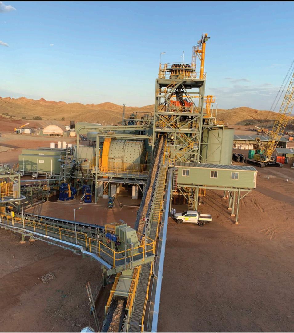
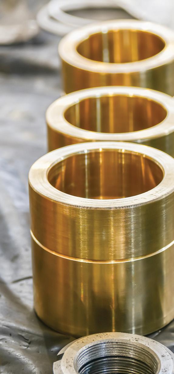
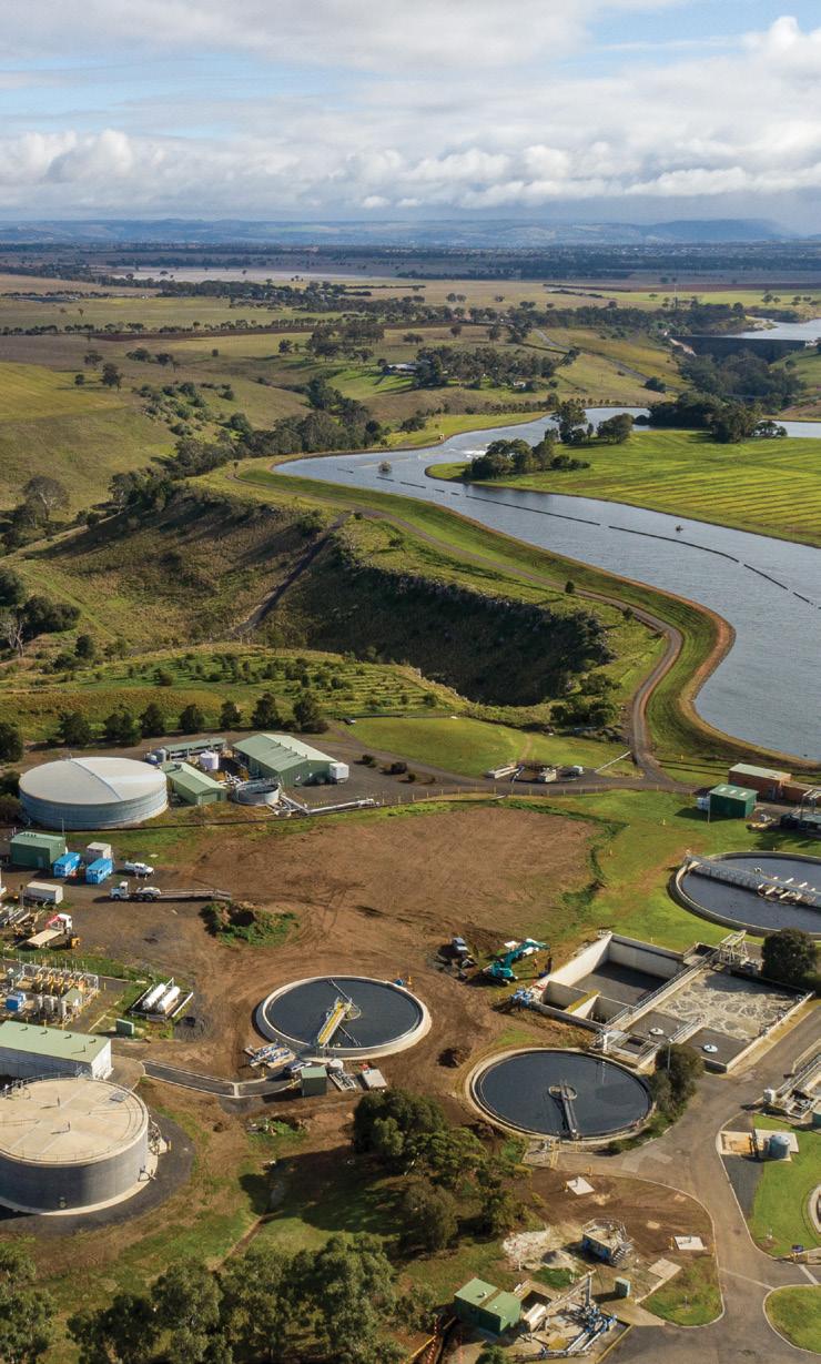
WATER AND WASTEWATER SOLUTIONS COMPANY ACQUIRES VIC SEALS AND PUMP BUSINESS
An Australian-Singaporean water and wastewater treatment solutions company has acquired a seals and pump business in Victoria, expanding the range of products and services available.
Stevco Seals & Pumps Victoria has been acquired by De.mem, and all business operations will continue under the new company name, De.mem-Stevco.
Steve Russell and James Blannin, of Stevco, will retain their executive director roles and join the De.mem senior management team.
With the transaction, David Rae, the existing regional manager of De.mem group for Victoria and South Australia, is becoming a director of the entity.
De.mem Limited is an Australian headquartered, ASXlisted decentralised water and wastewater treatment business. De.mem serves a long-term client base from the mining, food and beverage, agricultural, municipal, and heavy industrial segments.
Through workshops in Melbourne, Brisbane, Perth and Launceston, De.mem has the ability to serve its clients nationwide.
The company employs a total of 58 staff in Australia plus another 22 overseas. International locations are in Singapore and Velbert, Germany.
It is commercialising an array of innovative proprietary technologies from its research and development partner, Nanyang Technological University (NTU) in Singapore, a world leader in membrane and water research.
Technologies uniquely offered by De.mem include a revolutionary low-pressure hollow fibre nanofiltration membrane that uses less electricity and is cheaper to operate than conventional systems, as well as a new Forward Osmosis membrane deployed in dewatering applications or the concentration of liquids.
Besides the supply of pumps and related services, the group offers a wide range of advanced products, services and solutions for industrial water and wastewater treatment applications:
• Water and wastewater treatment equipment including:
» Membrane based water treatment plants
» Industrial wastewater treatment plants customised to the specific requirements of a client
» Sewage treatment plants
» Chemical dosing systems
• The operations and maintenance of all of the above, with the scope of services tailored according to the requirements of the customer
• Specialty chemicals for water treatment and industrial processes, such as:
» Scale and corrosion inhibitors
» Cooling tower water treatment chemicals
» Process additives such as defoamers, dewatering aids, cleaning aids, and emulsifiers
» Bespoke chemicals to customer requirement
• All common water and wastewater treatment components and consumables, including Ultrafiltration membranes manufactured at De.mem’s factory in Singapore.
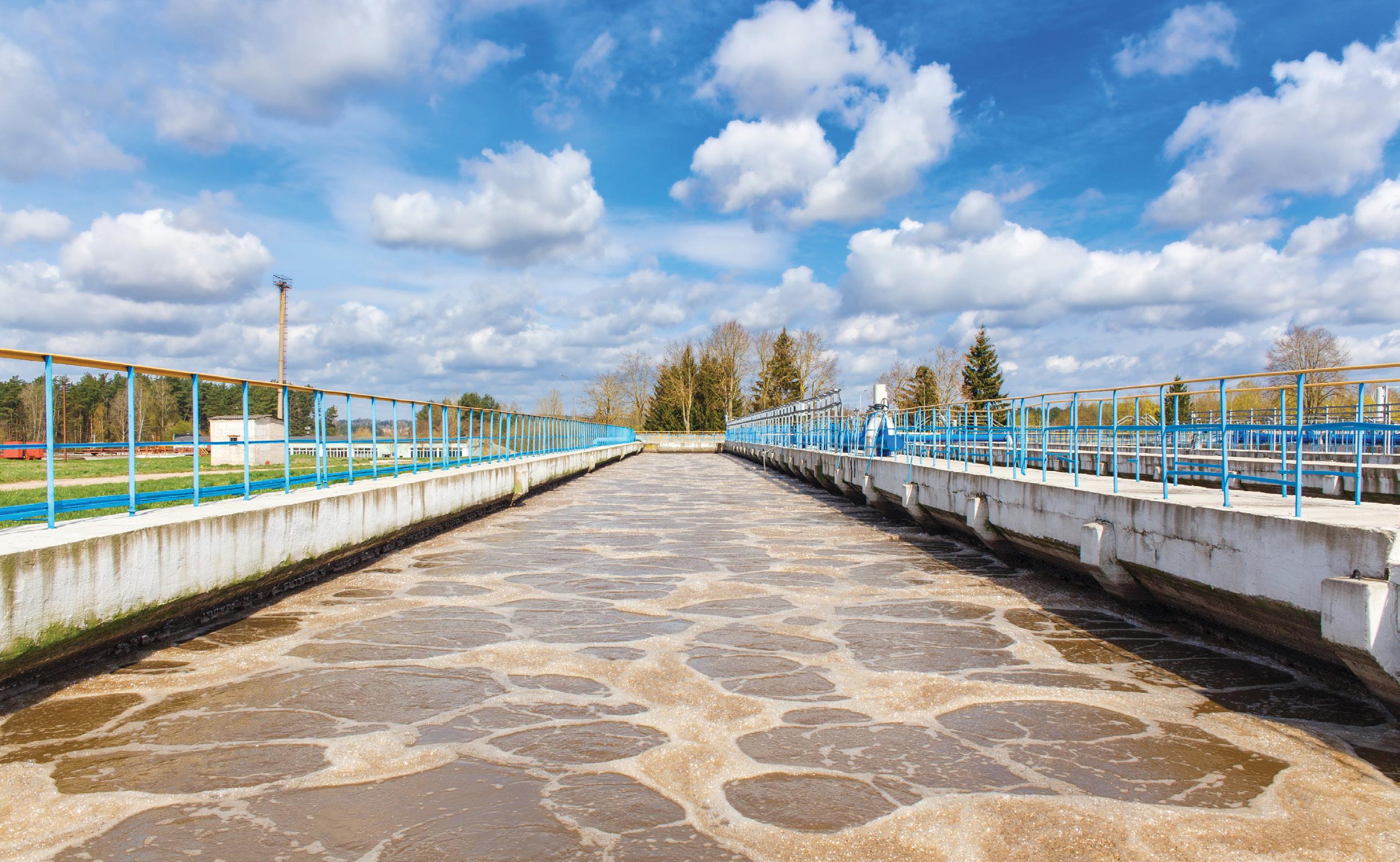
De.mem’s products meet highest quality standards. The company’s equipment is assembled and its specialty chemicals offering blended at the relevant facilities in Brisbane and Perth, Australia.
With the extended product offering and capability range as described above, De.mem-Stevco will continue operations out of its workshop in Epping, Victoria, backed up with support from De.mem’s national and international locations.
$24.8M FOR RECYCLED WATER pipeline in Melbourne’s South East
The Victorian Government has announced $24.8 million in funding for the Dingley Recycled Water Scheme, which will include a new 42km pipeline to deliver recycled water to Melbourne’s South East.
The pipeline will deliver 1,800ML of recycled water to 46 sites, including parks, golf courses, sports ovals, laundromats, market gardens and nurseries in the Kingston, Monash and Bayside communities of Melbourne.
This funding is part of a $56.6 million investment announced in the Victorian Budget 2022/23 to support the delivery of the Central and Gippsland Regional Sustainable Water Strategy.
The strategy sets out the State Government’s long-term plan to improve water security, liveability, and waterway health for the next 50 years.
The Dingley Recycled Water Scheme will cost a total of $72 million, partly funded by South East Water.
Victorian Minister for Water, Lisa Neville, said using more recycled water responds to the needs of the growing population sustainably by delivering green public spaces all year round without impacting the drinking water supply.
“Those who remember the Millenium drought in the 2000s will know the impact on businesses, parks and sporting fields and communities – this initiative will provide a rainfall independent water supply,” Ms Neville said.
The construction stage will generate around 38 fulltime jobs.
Once complete, the project will support international golf tourism which generates 240 jobs, and provide a climate resilient source of water for connected local businesses in the event of drought.
The project is set to generate $92 million for the local economy.
Member for Keysborough, Martin Pakula, said, “Victoria boasts some of the best golf courses in the world and this project will help keep our courses greener and attract more golfers to play in Melbourne’s South East.”

Investing in recycled water infrastructure supports Victoria’s response to climate change impacts.
It allows parkland and golf courses to remain green during dry spells, open up new horticulture business opportunities and tourism, and provide the community with high-quality public open space all year round.
South East Water Acting Managing Director, Charlie Littlefair, said, “Recycled water projects help build resilience into our water systems, strengthening our entire water supply network and helping more of our customers and the community to harness the benefits of a rain independent source of high-quality water.”
The new pipeline will help diversify Victoria’s water sources and meet future water demands of the area’s growing population without impacting on the drinking water supply.
Recycled water is expected to become available by 2025.
At Brown Brothers Engineers we have the most comprehensive range of quality pumps and innovative pumping solutions. We are the distributor for some of the world’s leading brands including:
WELCOME TO THE BIG END OF TOWN.
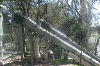
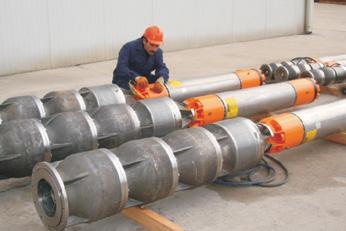
VERTICAL TURBINE PUMPS
Layne Bowler vertical turbine pumps have a proven record under the most demanding and toughest of conditions.

• Flows to 2,300 L/Sec
• Heads to 350 m
• Power to 1000+ kW
• Temperatures to 150°C
• Bowls Diameter up to 45 inch
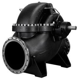
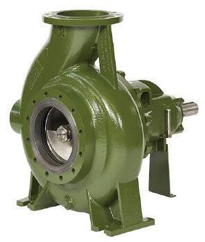
When high head and high flows are required look no further than this quality Italian made range.
• Flows to 5000m³/h

MORE EFFICIENT PUMPS HELP YALATA’S DESAL PLANT’S SUSTAINABLE SUCCESS
Three months after starting water production, Yalata’s new state-of-the-art desalination plant had consistently reduced its power consumption by around 400 per cent compared to its predecessor, partly due to more efficient pumps.
A combination of more efficient pumps, economies of scale and scheduling production for times of peak solar radiance, saw energy consumption fall from an average of 10,000kW hours per quarter prior to the upgrade to just over 2,000kW hours.
Located in South Australia’s Far West Coast, the new facility delivered more than five million litres of water to local residents and businesses in the Indigenous community during its first three months of operation.
SA Water’s Senior Manager of Water Expertise and Research, Dr Daniel Hoefel, said the Yalata plant’s solar generation capacity has made it largely energy self-sufficient.
“Through clever design and construction, we’ve increased the plant’s capacity to secure a reliable water supply for our customers, while also reducing our environmental footprint,” Dr Hoefel said.
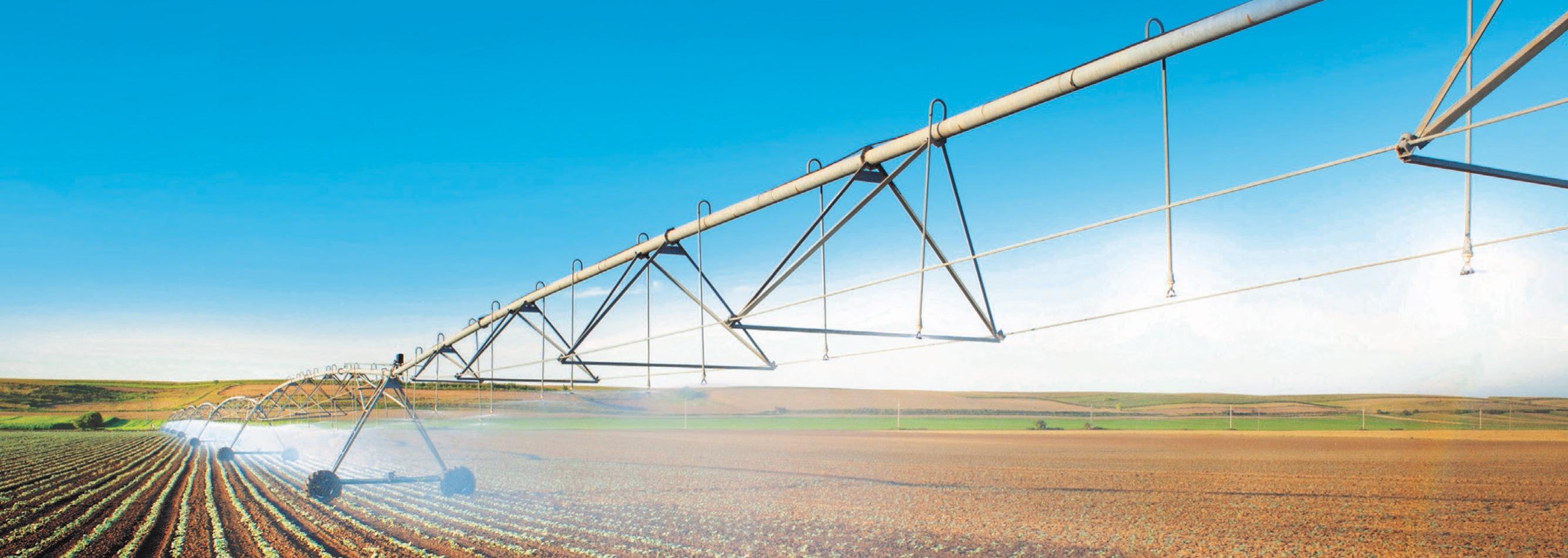
“Our new plant – which is capable of producing 180,000L of water per day – is predominantly powered by a 40kW solar
array with backup storage, and with increased throughput we’re able to produce enough water while the sun is shining to meet customer demand during the day and store water for supply overnight,” Dr Hoefel said.
In its first quarter of operation, the new desalination facility used a fraction of the energy required to power the old plant.
“The old plant’s energy consumption got as high as 22,000kW hours per quarter last year, so it’s fantastic to see the new plant harnessing more clean energy to reduce greenhouse gas emissions and operational costs,” Dr Hoefel said.
“With our extensive water and wastewater operations across South Australia making us one of the state’s largest electricity consumers, we want to set an example as proactive environmental leaders by investing in sustainable infrastructure projects to help combat our changing climate.
“Importantly, upgrading our plant in Yalata ensures safe, clean drinking water into the future to support the health and wellbeing of the local Indigenous community.”
Yalata’s new desalination plant utilises reverse osmosis technology to remove the naturally-occurring impurities like high levels of salinity, common within inland groundwater sources.

New well and valve configuration for Wallerawang SPS
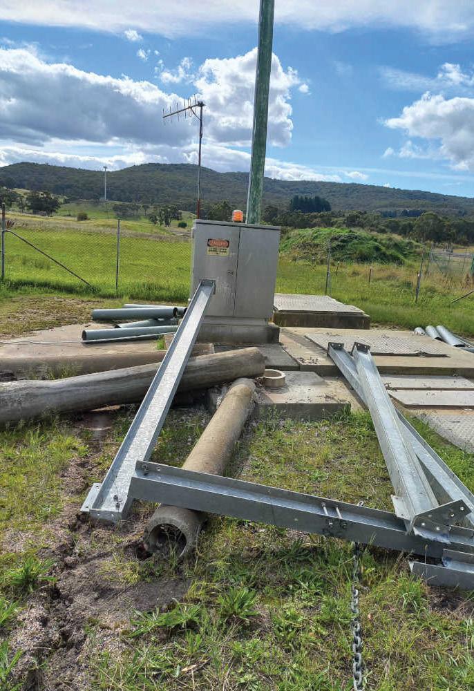
Lithgow City Council has announced a project to upgrade the Wallerawang sewerage pumping station, including a new well for emergency storage and new valve configuration.
Wallerawang’s sewerage infrastructure is currently undergoing important renewal works to cope with additional flows from new development in Wallerawang.
The upgrade will deliver more efficient equipment which will reduce the running costs of the plant and provide greater storage volumes in the case of emergencies and shutdowns. This is better for the environment, as well as being more cost-effective.
A new, larger well was being constructed with increased emergency storage, and a new valve configuration which will improve operations and ensure the plant is operating to modern standards.
Lithgow City Council said it is focused on this issue because good sewerage infrastructure not only supports the daily lives of people and a city’s operation and growth, it also safeguards the environment.
The project was expected to be completed by the end of June 2022 and delivered under budget.








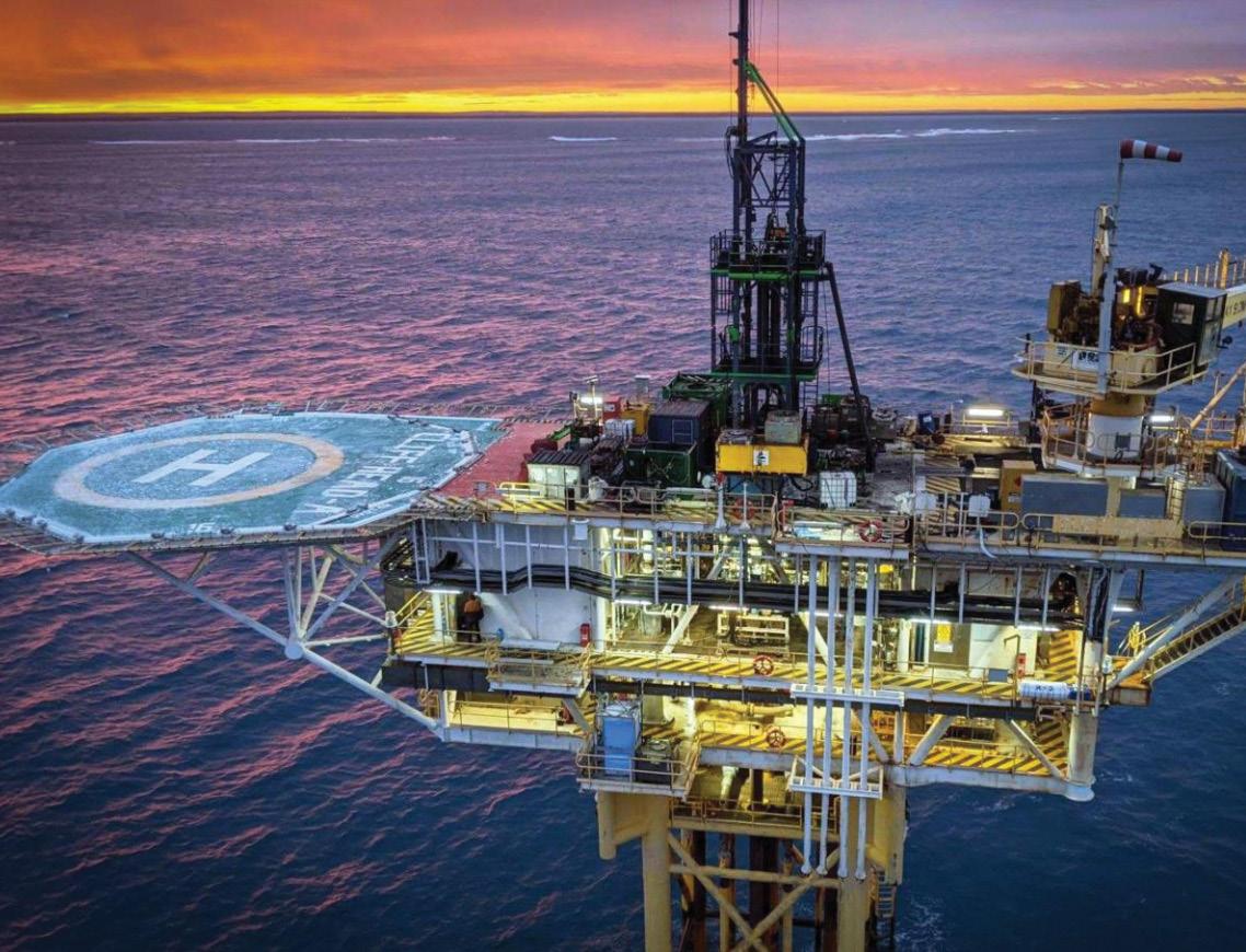
CLIFF HEAD JOINT VENTURE TO REPLACE FAULTY ESP
The Cliff Head Joint Venture (CHJV) will undertake a phased campaign to recover a failed electrical submersible pump (ESP) and replace it with a new ESP.
The CH-10 well was shut in September 2021 due to a downhole electrical fault. This well had produced reliably for nearly 12 years with the same ESP and this performance significantly exceeds the field average of four years.
Activities will now begin on the CH-10 Workover to replace the failed ESP and increase hydrocarbon production from this well. Over the coming months, the CHJV (made up of Triangle Energy and Pilot Energy) will undertake a phased campaign to recover the failed ESP and replace it with a new ESP.
In addition, a deeper water producing reservoir will be isolated, with the aim to increase oil production. The phased approach to this workover optimises the utilisation of the Hydraulic Workover Unit and budget spend in alignment with long lead item delivery schedules.
The CHJV expects the successful workover will produce an additional circa 130 barrels of oil per day (bopd) from CH-10 and see field production return to above 800 bopd.
Further updates will be provided as the workover progresses.
Triangle Managing Director, Conrad Todd, said, “I am pleased to report to shareholders that the Cliff Head Joint Venture has commenced the CH-10 well workover.
“This will allow the CHJV to restore the production lost due to failure of the downhole pump and furthermore to increase production by shutting of water from a deeper reservoir.”
ENGINEERED INDUSTRIAL PUMPING SOLUTIONS

CONSTRUCTION BEGINS ON $95M PIPELINE FOR SOUTH EAST QUEENSLAND
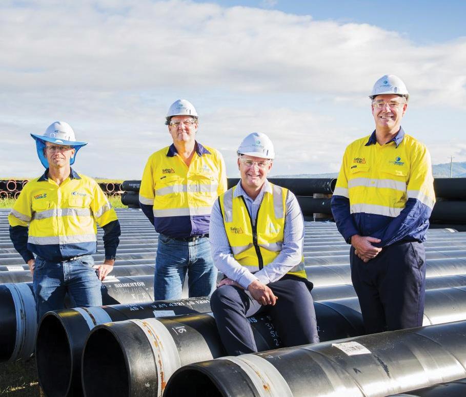
Construction has begun on a $95 million pipeline to connect two reservoirs to the South East Queensland Water Grid, with a new pump station also planned for construction at the new Wyaralong Water Treatment Plant at the same time as the pipeline.
The South West Pipeline is the second stage of the Beaudesert Water Supply Upgrade, a long-term water supply solution for the Scenic Rim.
The 27km pipeline will connect two recently-built reservoirs at the existing Beaudesert Water Treatment Plant to the SEQ Water Grid.
The design and construction tender for the pipeline was awarded to Comdain Infrastructure, a national leader in delivering critical gas and water services.
Queensland Minister for Water, Glenn Butcher, said the pipeline that was being built would connect Beaudesert to the SEQ Water Grid to support population growth and economic development in the area.
“The Scenic Rim is experiencing a period of significant growth, with more than 67,000 people expected to call this community home by 2041,” Mr Butcher said.
“The area has also become a regional hub for large-scale freight and transport operations, thanks to the Bromelton State Development Area.
“Connecting Beaudesert to the SEQ Water Grid will shore up local water security for years to come, giving confidence to households and businesses that they can continue to grow and prosper in this wonderful part of the South East.”
Seqwater Chief Executive Officer, Neil Brennan, said the pipeline will be the biggest addition to the SEQ Water Grid since completion of the Northern Pipeline Interconnector in 2012 to connect water supplies between Brisbane and the Sunshine Coast.
“Connecting Beaudesert to the SEQ Water Grid will ensure a reliable long-term water supply for the Scenic Rim by making it easier to move water into the region when needed,” Mr Brennan said.
“The way the SEQ Water Grid connects drinking water supplies across our region is a unique system in Australia.
“It provides us with more options to manage water supply challenges arising from sporadic rainfall, drought, climate change and population growth.
“We are continuing to invest in water infrastructure projects to ensure our region has a secure and adaptable water supply, now and for future generations.”
The project team has now commenced laying pipeline in a staged approach along the alignment, with work to be completed in late 2022.
Specialising in custom design, manufacture, repair and service of centrifugal pumps for over 30 years
• Complete range of API 610 (ISO13709)
• Hydraulic and mechanical design
• Custom engineering, retro-fit, redesign
• Performance testing
• Service and repair
UNITED PUMPS
www.unitedpumps.com.au
T: +61 3 9464 9500
31 Western Avenue, Sunshine Victoria 3020, Australia
E: unitedpumps@unitedpumps.com.au


Approvals granted for Woodside’s Scarborough joint venture
Woodside has received initial state and federal approvals for its Scarborough joint venture off Western Australia, which involves a floating production unit and gas pipeline.
Approval was granted for the project’s field development plan, with the first liquified natural gas exports from the project targeted for 2026.
The project field is approximately 375km away from the Western
Australian coast, and is estimated to contain 11.1 trillion cubic feet of dry gas.
Queensland Minister for Resources and Water, Keith Pitt, has welcomed the announcement as an important step forward for the project.
“The approval for a pipeline licence through state and Commonwealth waters, along with the Scarborough Field Development Plan, are significant for the US$12 billion project, which will provide a huge jobs and economic boost
for Western Australia and the nation,” Mr Pitt said.
“Apart from unlocking enormous gas reserves, it’s estimated the project will have a peak construction workforce of over 3,000 and 600 jobs once it’s operational, including around 230 in the Pilbara.
“Given the current uncertainty around the world, and an energy crisis throughout Europe, it’s projects like this that build Australia’s capacity to ensure long-term energy and national security.”

Irrigation Water Systems
featuring HYDROVAR® or a custom control system.
Create a variable speed booster station to your technical specifications.
– Maintain constant pressure – Optimized pumping efficiencies
– Longer lifetime and reduced lifecycle costs
Lowara’s extensive pump range together with our large selection of custom control options, offers a complete line of booster systems ideally suited for the diverse requirements of irrigation applications.
Contact us to find your solution.

CONSTRUCTION OF KIDSTON PUMPED STORAGE HYDRO PROJECT HITS NEW MILESTONE
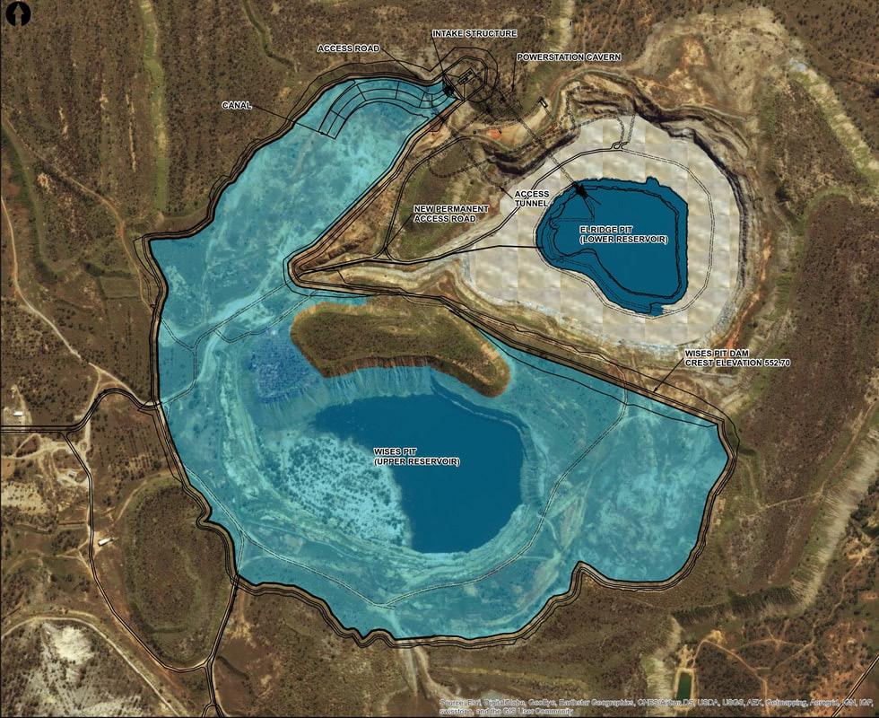
The latest milestone for the $777 Kidston Pumped Hydro project saw the first workers begin construction on Wises Dam, which will be able to deliver up to 4.5GL of water to spin the project’s turbines.
Queensland Minister for Energy, Renewables and Hydrogen, Mick de Brenni, said 120 workers had begun building Wises Dam in April.
The dam is a critical element of the Genex Kidston Pumped Storage Hydro Project – a world-first integrated solar and pumped-hydro storage project.
Mr de Brenni said the project was delivering jobs ahead of power with 120 workers on site, a further 100 workers mobilising before June, reaching a peak of 430 persons on site by the middle of 2023.
The Kidston Pumped Storage Hydro Project and its associated transmission infrastructure is expected to be completed and fed into the National Electricity Market by early 2025.
It is one year into the project delivery phase, and the construction of the dam marks a significant milestone as it is the largest piece of the surface construction work. The site establishment is complete and construction activities
remain on track to commence generation before the end of 2024.
Genex and its partners are converting the former Kidston Gold Mine into a clean energy hub which will combine wind, solar and pumped hydro storage and make a major contribution toward the Queensland Government’s target to achieve 50 per cent renewable energy by 2030.
Mr de Brenni said the project will deliver cleaner, renewable energy, which means lower emissions and cheaper power for Queensland households, businesses and industry.
“The Queensland Government committed $147 million towards
essential transmission infrastructure built by publicly-owned Powerlink to link Kidston to the east coast energy grid.
“Wises Dam, the project’s upper reservoir, will be able to deliver up to 4.5GL of water to spin the project’s 2x125MW turbines for up to eight hours,” Mr de Brenni said.
Resources Minister and member for Townsville, Scott Stewart, said Wises Dam construction sets a global example for effective transformation of legacy mining sites.
“This project will not only power homes and jobs, it will also help pave the way for more mining rehabilitation success stories across Queensland, as we work to breathe new life into old sites,” Mr Stewart said.
Genex Power Chief Executive Officer, James Harding, said the project is the company’s flagship project and the first of its kind to be developed in Australia in more than 40 years.
“This is essentially a giant water battery which will provide 250MW of electricity generation for up to eight hours, sufficient to satisfy Townsville’s peak power demand.”



$4.5M sewer upgrade for historical VIC town

Anew $4.5 million sewer upgrade project is underway in Beechworth, Victoria, including a 4km-long sewer transfer pipe and a new pump station to address sewage overflows to the Beechworth Historic Park.
North East Water is in the process of installing the sewer transfer pipe and the new pump station.
Executive Planning and Infrastructure, Rebecca Jhonston, said construction work is now around the halfway point.
“Our contractor has just finished a difficult one kilometre horizontal ‘long bore’ from the sewage treatment plant at Woolshed, under the Historic Park and through to Old Chiltern Road in Beechworth,” Ms Jhonston said.
“This was a monumental task which required drilling through some extremely hard granite.
“They have also just pulled a continuous segment of pipe back through the horizontal bore, with the pipe having to be welded together in large sections above ground before being pulled through.
“This piece of work is a great environmental outcome for the Historic Park as construction was only necessary at each end of the bore.”
Ms Jhonston added, “The community will now see activity in the busier areas of town, with pipe work to soon begin along Last Street and Sydney Road.
“There will be traffic management in place along the route involving partial road closures and speed restrictions.
“We are aiming to have this project completed by the end of the year, dependant on the weather.
“I would like to thank the community for their patience as we work to deliver this critical piece of infrastructure.”
Initial planning work has also commenced to upgrade the town’s sewage treatment plant which will be necessary to take extra flow from the new transfer main, as well as accommodate future population growth.
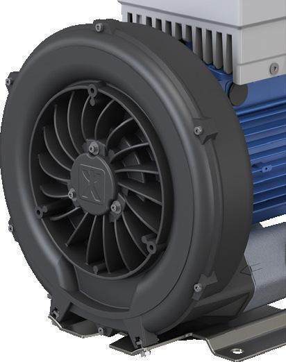
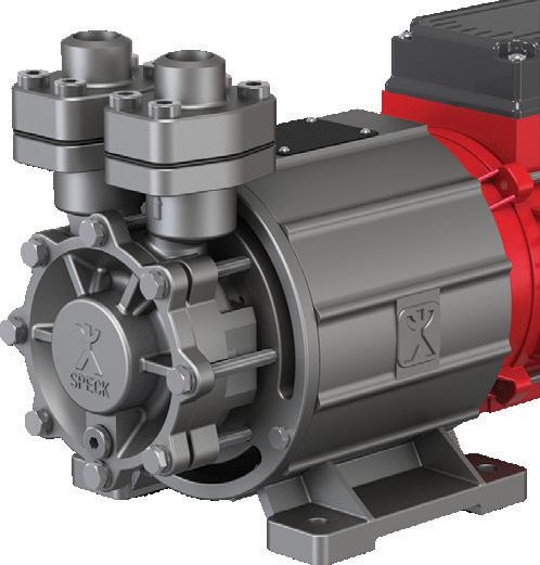
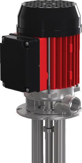
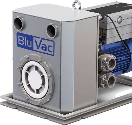
MORE THAN 100 YEARS’ EXPERIENCE OF MANUFACTURING PUMPS
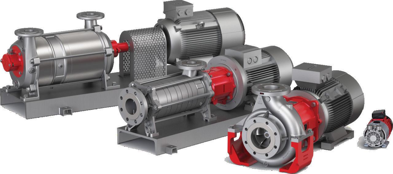
Our specialised products are principally used in medical technology, the chemical and pharmaceutical industries, cooling and tempering appliances and in the plastics industry. Speck is very export-oriented and employs over 575 staff members worldwide.
Products from Speck are characterised by a wide range of available variants which is specially tailored to the customer’s needs. Our staff in the Technical Department are constantly working on new solutions and further developments to our existing products that help our customers move forward – day in, day out.
Industrial Segments
WEG launches W12, a light and versatile motor for industrial applications
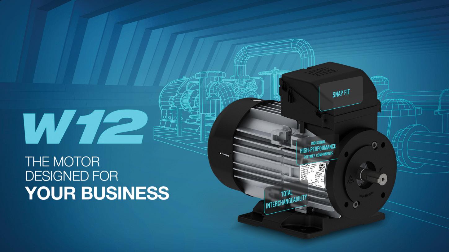
The new W12 electric motor from WEG is designed for use in higher performance industrial applications whilst offering versatility and efficiency.
Featuring high-strength industrial polymer flanges, feet, cover and junction box, and an unmachined aluminium housing, the motor has the lowest weight for robust applications, such as pumps and gearboxes.
The aluminium frame of the WEG W12 motor is designed to optimise the heat exchange and provide mechanical strength to meet the most critical applications. The frame also has guides to ensure the accuracy and rigidity of the assembly after mounting the feet or flanges.
Being an extremely versatile piece of equipment, its interchangeable feet meet all the relevant IEC standards. Currently available in frames 56, 63 and 71 housings, the W12 motor also allows the option of using the connection box on the side or at the top, all in the same product. The variations are made by the quick fit system of the feet in the frames (snap fit), dimensioned not to use fixing screws, and also in the flange options C-90, C-105 and FF115 in polymer, and C-80 in aluminium, incorporated in the motor frame.
The W12 motor is totally enclosed and fan cooled, incorporating a click-on fan cover which guarantees high
mechanical rigidity and high impact absorption capacity. These components comply with the IK08 impact index, according to EN 62262, which guarantees use in more severe applications.
This motor features an IP55 degree of protection (waterproof and dustproof), which allows use in the most diverse environments. W12 motors have a drainage system to prevent accumulation of condensed water and the entry of unwanted substances into the motor, preventing corrosion or damage to internal components. This makes it the perfect solution for pump applications. In addition, the W12 has versions in 2, 4 and 6 poles, from 0.09 up to 0.55kW, threephase or single-phase power and IE3 performance index.
With the evolving W12 range, WEG will be releasing frames 80 to 100 (up to 3kW) later this year, incorporating all the same benefits as this newly released motor designed specifically for industrial applications.
A notable entry in the manufacture of high efficiency motors, innovative solutions and in the technological development of the industry, the W12 is yet another versatile and efficient solution with the guarantee and reliability that comes standard with a WEG product.
W12, the motor designed for your business.

ICONIC SWIMMING POOL chooses Ebara GSD pumps for filtration pump upgrade
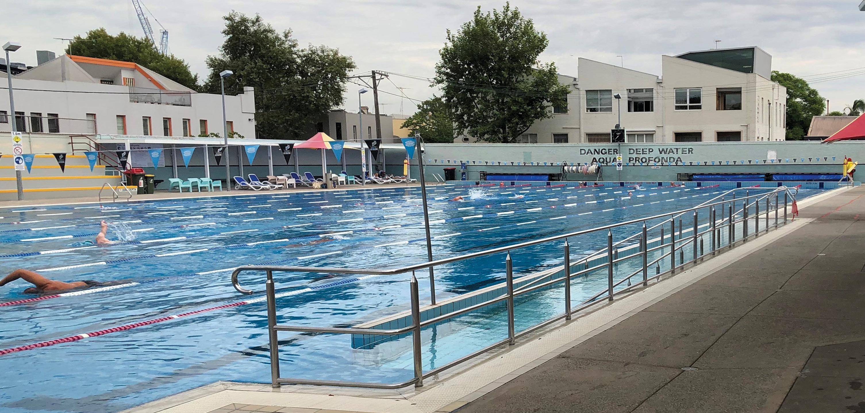
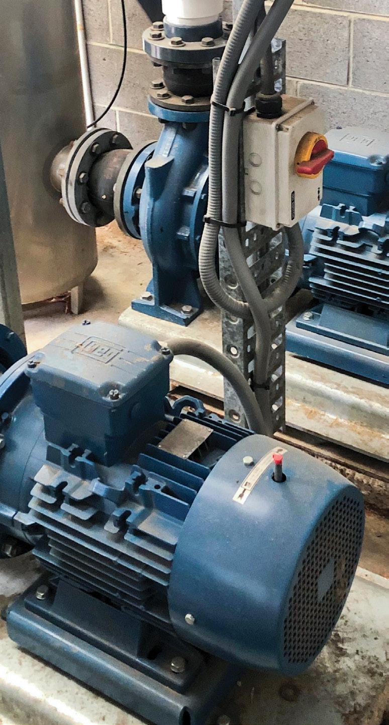
The iconic Fitzroy swimming pool, operated by the Yarra City Council and Yarra Leisure, has recently installed three new Ebara GSD 100-250/11kW close coupled EN733 motor pumps as part of its filtration pump upgrade.
The Ebara GSD motor pump was chosen by mechanical services contractor, Mechanical Plumbing Services (MPS), due to its quality, proven hydraulic design and competitive pricing. The GS/GSD pumps come as standard with a high-quality electro deposition corrosion-resistant coating to the ferrous static components, both internal and external, making them ideally suited to harsh swimming pool environments.
The GS/GSD range is the Ebara Corporation (Japan) new global range of EN733 water pumps and utilises the most advanced hydraulic computer software available. Ebara Engineers in Japan have been able to improve and increase the pump efficiencies of the new GS/GSD range above most other available pumps of similar design and standard on the global market. The majority of the GS/GSD pump range are MEI>0.7 efficiency index with the balance MEI>0.6, an indication of the high-quality design and manufacture by Ebara.
The Ebara GSD range of close coupled motor pumps and the GS range of bare shaft EN733 end suction pumps are both manufactured in component form at Ebara Corporation (Japan)-owned and managed factories in South East Asia.
After being assembled from these components by skilled tradesmen at the Ebara Pumps Australia facility in Melbourne, the pumps are then hydrostatically tested and inspected to our Japanese parent’s strict QA policies and procedures.
The Ebara GS/GSD range of EN733 pumps are a true 16 bar working pressure with a high grade SiC/Carbon/EPDM Burgmann mechanical seal fitted as standard. Galvanised steel baseplates that have been fully engineered by Ebara Japan engineers are also available as an optional extra for the GSD motor pumps.
About Ebara Corporation
Ebara Corporation was founded in Japan in 1912 as a manufacturer of industrial pumps. Today, as a group, it consists of more than 70 companies in six continents with a workforce of more than 12,000 and with company-owned and Japanese-managed factories covering nine countries and four continents.
The huge scale of production and distribution is matched by a constant commitment to research, development and design of new products and the modern technologies for the manufacturing of them. Ebara products have gained a worldwide reputation for their technology and quality.
New hydraulic design - World leading performance
Combining over 100 years of experience with the latest computer aided design, EBARA has developed the new GS series of pumps that offer world leading performance and efficiencies.
End suction single stage centrifugal pumps
Pumps to EN733 dimensions
16 Bar rated. PN16 flanges (24 Bar hydrostatic test pressure)
High efficiencies. MEI ³0.6 (Minimum Efficiency Index)
Mechanical seals to EN12756
Protectors to ISO13852
O’ Ring seal for casing
Cast iron components ED painted (Electro deposition painting)
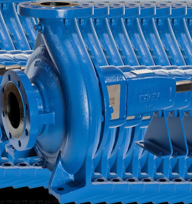
Model GS
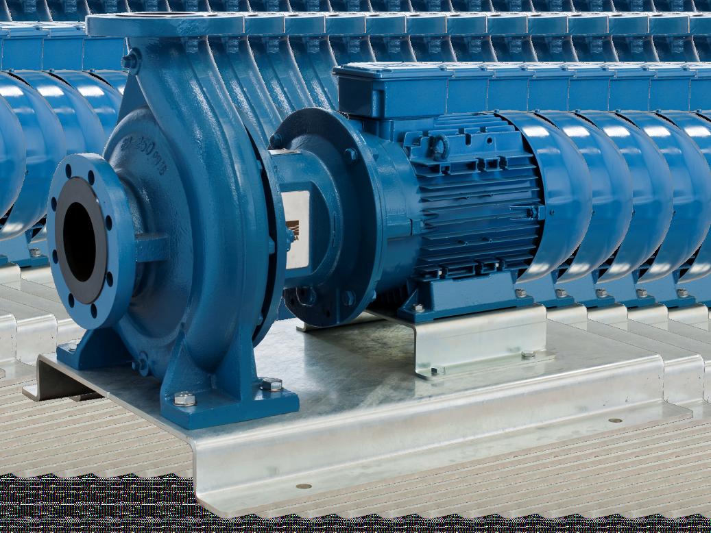
Model GSD
GAME-CHANGING BOOSTER SET TECH MAXIMISES PUMP EFFICIENCY
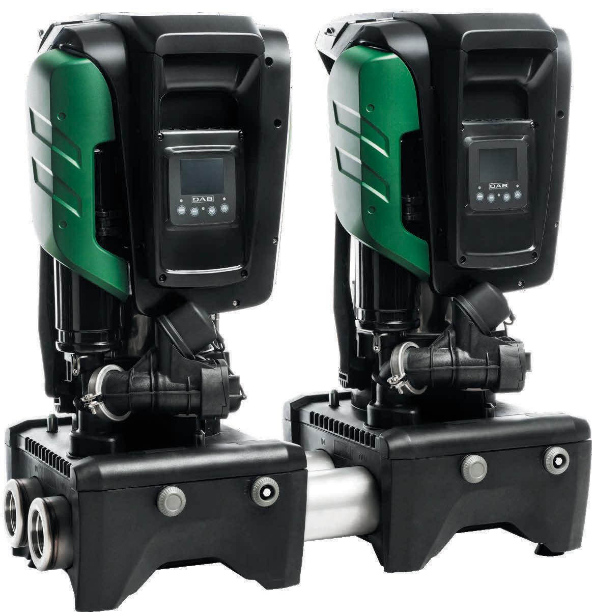
DAB Pumps is introducing commercial building services to a new concept and industryfirst product that is supercharging the booster set industry – the EsyBox Max, an integrated pumping system for pressurisation. Available in two power sizes, it consists of modular elements that allow different configurations to cover the needs of medium and large apartment blocks and high buildings, even over 14 floors.
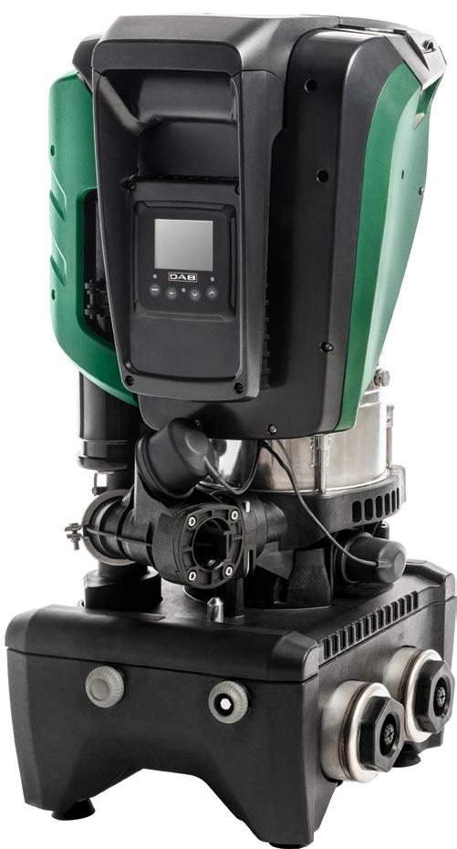
Each unit consists of the single, double or triple connection base and the pumping units – a four-pump system is available with the additional kit to connect two double bases.
Large energy savings are achieved with the DAB inverter combined with a brand new permanent magnet motor. DAB also designed completely new hydraulics, making it leaps ahead in terms of energy efficiency. But it is not just energy efficiency that is at the forefront of this new technology.
Esybox Max will improve the storage efficiency in the warehouse. Where there was once one booster occupying space, you can now fit three twin pump booster sets in its place. This allows people to store the full range on one pallet, meaning a customer can pick up an off-the-shelf booster solution of up to four pumps the same day.
“When we started to think about Esybox Max, we asked ourselves how to manage the evolution of the Esybox range. It was clear from the very beginning, it could not just be something bigger. We felt we had to bring forward the path of evolution, completely changing the rules of the game for booster sets in residential and commercial buildings. Esybox Max is the outcome of listening to and communicating with many different people who will be in direct contact with the product.”
Keeping it flexible, DAB has the on-site assembly concept. So if you have difficulties getting to the pump's location, due to narrow stairways and corridors etc., you can choose to assemble your booster on-site which will only require moving smaller, lighter boxes into the location then carrying out a quick and easy assembly.
DConnect
The Esybox Max also offers full connectivity and control using DAB’s DConnect technology which is built into the pump and offers many more advantages than typical BMS systems. Performance, data storage and remote monitoring support users, and facility managers can control their pumps from anywhere, making sure that the running parameters of the pumps follow project specifications exactly and avoiding any possible site issues for complete peace of mind.
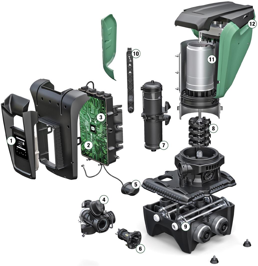
(7) Two Litre expansion tank (8) Impellers (9) Hydraulic connections
(10) Fast connection tool (11) Water cooled permanent magnet motor (12) Handles
LINE UP FOR THE FUTURE
State of the art efficiency
The DAB inverter has been combined with a brand new permanent magnet motor. We also designed completely new hydraulics, making it leaps ahead in terms of energy efficiency. LEARN MORE
Modular Integration
The most compact and integrated booster set on the market. Connect 1, 2, 3 or 4 Esybox MAX units.
Easy to maintain
Connect and control from anywhere with DConnect.
Easy to move & install
Quick On-Site Assembly.
Affordable web based remote control for your installation
With DConnect you can use your smartphone to connect directly with the pump using the simple interface. All adjustments are possible remotely, allowing total control with no unwanted surprises.

Bayswater ™ Mobile Hose Crate
reducing workforce demands
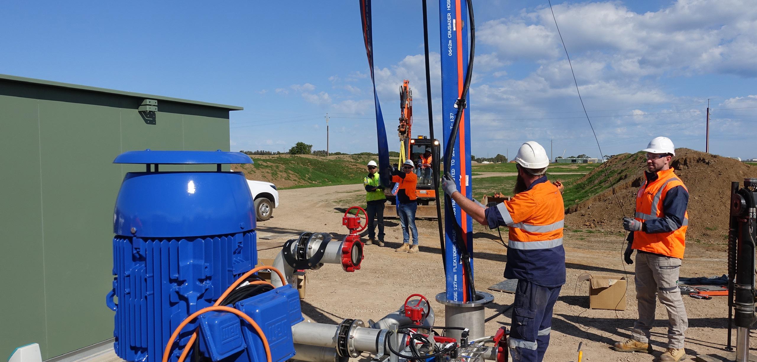
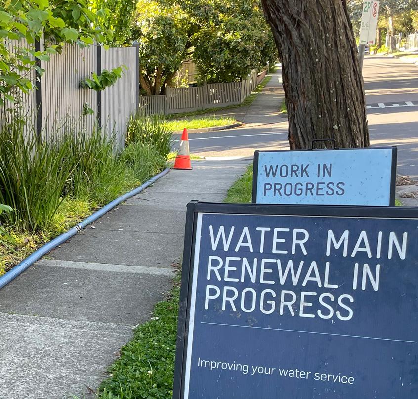
Farming, cattle grazing and the construction of dams have all contributed to changes in the waterways of the Lower Yarra River Floodplains in Melbourne, Victoria. Melbourne Water recently re-watered the Annulus Billabong for the conservation of many indigenous plants and birds. The Bayswater™ Mobile Hose Crate equipped with Waterlord® layflat hose from Crusader Hose was the solution for the temporary pipeline for the water transfer.
The waterways around Melbourne’s Lower Yarra River Floodplains have gone through many changes with urbanisation. Areas that were once natural habitats for indigenous plants and birdlife were converted to support farming, cattle and horse grazing. The regular flooding of rivers by rainfall, which is responsible for the lifecycle of billabongs, was affected by the construction of the Yarra Dam in the 1950s as well as by climate change. As a result, many billabongs located in the Yarra Flats dried up slowly, affecting the delicate ecosystem. The Annulus Billabong was one of these.
Efforts were undertaken in the 1980s to re-water the billabong using windmills and pumps. An island was created in its centre promising a haven for birdlife. Over time, however, the trees around the windmill grew too tall, and funding ran out.
The Melbourne Water Healthy Waterways Strategy listed the Annulus Billabong as a key waterway within the Wildlife Sanctuary and Conservation Area. Maintaining water levels is
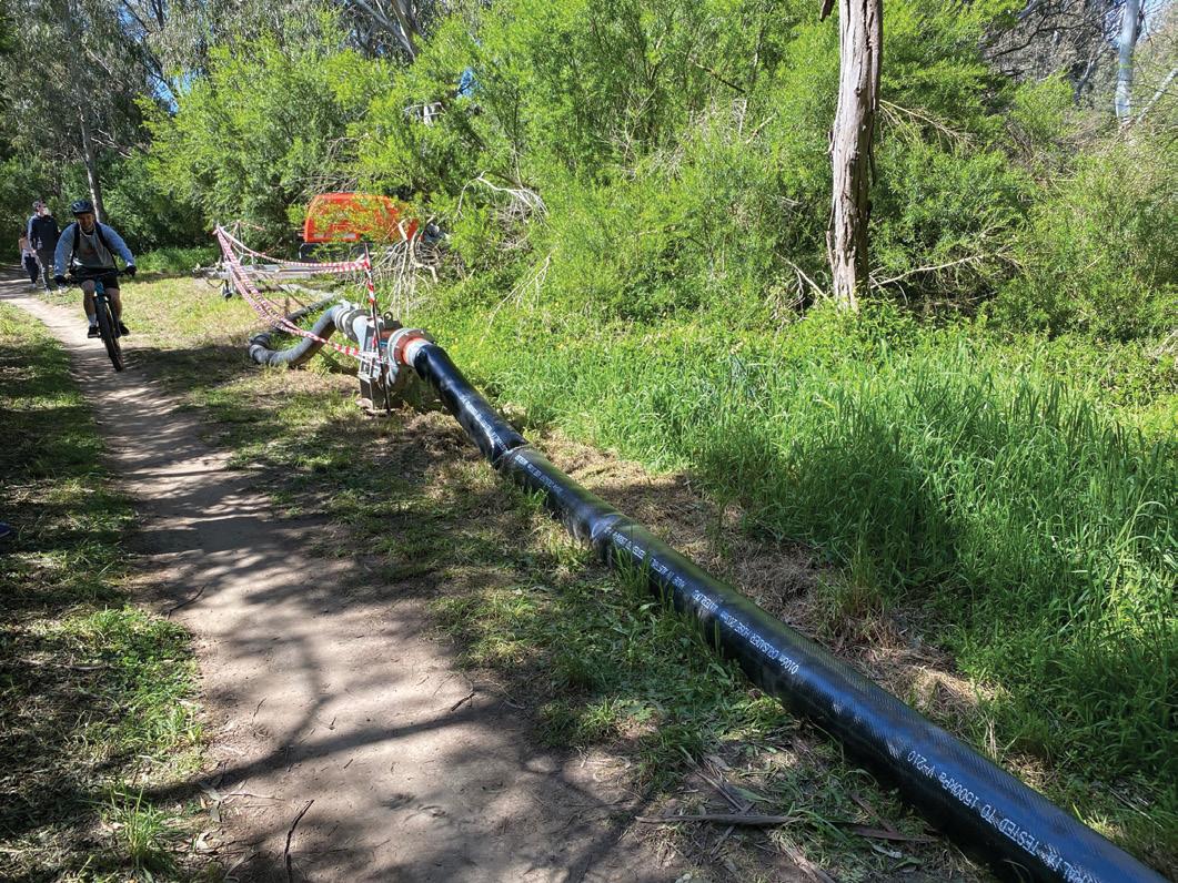
critical for the survival of many indigenous plants, attracting birds and restoring the indigenous landscape. The re-watering of the billabong commenced in October 2020 by pumping water from the Yarra River and bringing various organisms into the billabong ecology.
Bringing the billabong back to life
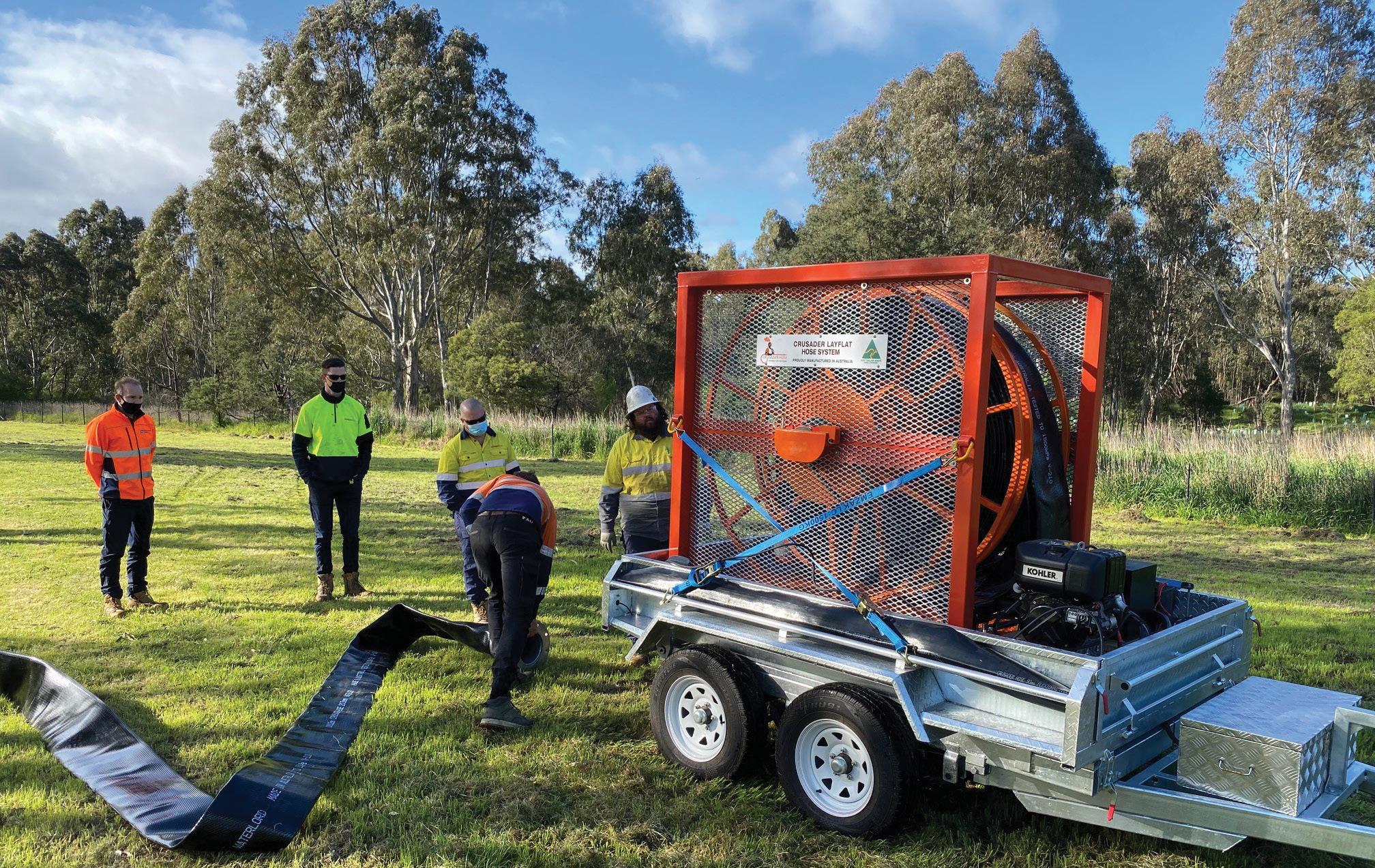
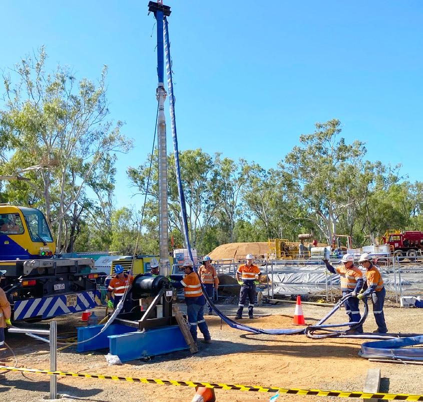
Layflat hose was chosen for the temporary pipeline for several reasons. Wound onto reels, smaller, lighter vehicles are used for their transport. Flexible layflat hose takes on the contours of its environment, reducing the need to dig or alter the terrain. The large diameter Waterlord® hose was a seemingly perfect solution for this re-watering project, however, the unrolling and re-rolling was physically demanding.
“Knowing the challenges of unrolling 200m lengths of 8” Waterlord® hose, we were keen to design a reeling system to remedy the situation. Our engineering experts designed the Bayswater™ Mobile Hose Crate,” said Francois Steverlynck, Managing Director of Crusader Hose.
Thys Stryker, Operations Manager of Coates Hire, who undertook the project again in September 2021, was more than pleased at the ease with which the Bayswater™ Mobile Hose Crate deployed the hose. Before, it took a whole day to roll out the hose manually, but with the reeling system, it took only three hours, with much less physical strain. The labour force was delighted.
“This ingenious reeling system can quickly and easily deploy up to 200m of hose in a fraction of the time it would take to do it by hand,” said Francois. “We are confident this will make the use of layflat hose a lot more desirable for many municipal works.”
The Annulus Billabong re-watering is now scheduled to be carried out every two years. The Bayswater™ Mobile Hose Crate with Waterlord® layflat can reduce the time and effort to complete water transfer projects. It’s proved itself as the system of choice.


SAER launches new wastewater division
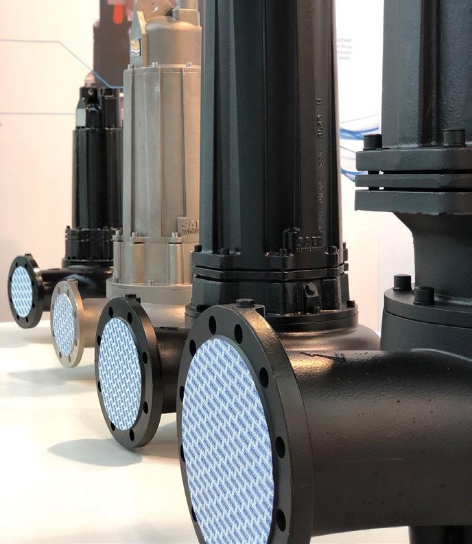
In this historical period where scarcity of raw materials and supply difficulties are an everyday issue, SAER has decisively responded with a made-in-Italy product range, with extremely competitive delivery times. Indeed, in the water treatment sector fast delivery is vital, but so is providing customised solutions to satisfy clients’ needs.
In order to meet the needs of clients in search for alternatives in the wastewater market, over the last few years SAER has been investing in the research and development of its newest ranges for wastewater: the SD range of submersible sewage pumps, and the NCA range of end suction wastewater pumps.
SAER – a specialist in the clear water sector for over 70 years – channelled its experience to conceive highlyefficient products, without giving up on robustness and durability.
SD range
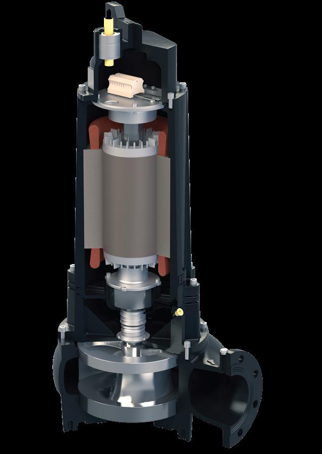
Let’s look in detail at the characteristics of the SD series, whose range goes from 2m³/h up to 2000m³/h with head from seven to 54m, and is characterised by its “armoured” build, granting an incredible impact and corrosion resistance.
Waterproof
• Coming from SAER’s unmatched knowledge in borehole pumps and submersible motors, the cable output is waterproof, tested against water penetration up to 20 bar
• Easy maintenance and high safety standard, with a single cable that includes power and signal conductors
Smart
• Watertight and wide connection chamber
• Organised and simple terminal block studied for easy maintenance
Wear resistant
• Wear disc between impeller and pump body provided with cutting channel
• Two-component epoxy paint with corrosion resistance according to EN 12944-6 grade C3-M
Reliable
• AISI 431 stainless steel shaft or with Duplex shaft end
• Optimum torque transmission, reduced material stresses and easier maintenance thanks to a shaft and impeller hub with polygon profile
• Long life bearings for a life of approx. 100,000 hours in continuous (MTBF)
Energy savings
• SAER premium efficiency motors are IE3 from 0,75kW up to 132kW, 2, 4 or 6 poles
• Hydraulics designed and engineered with CFD systems (Computational Fluid Dynamics) to combine efficiency, performance and free passage
Safe
• Exclusive double mechanical seal in oil chamber protection for troublefree operation. Process side seal in Silicon Carbide/Silicon Carbide (on request Tungsten Carbide or other materials)
• Protection probes for humidity, temperature and overheating
Versatile
• Several types of impellers available: vortex, open, closed or propeller
NCA range
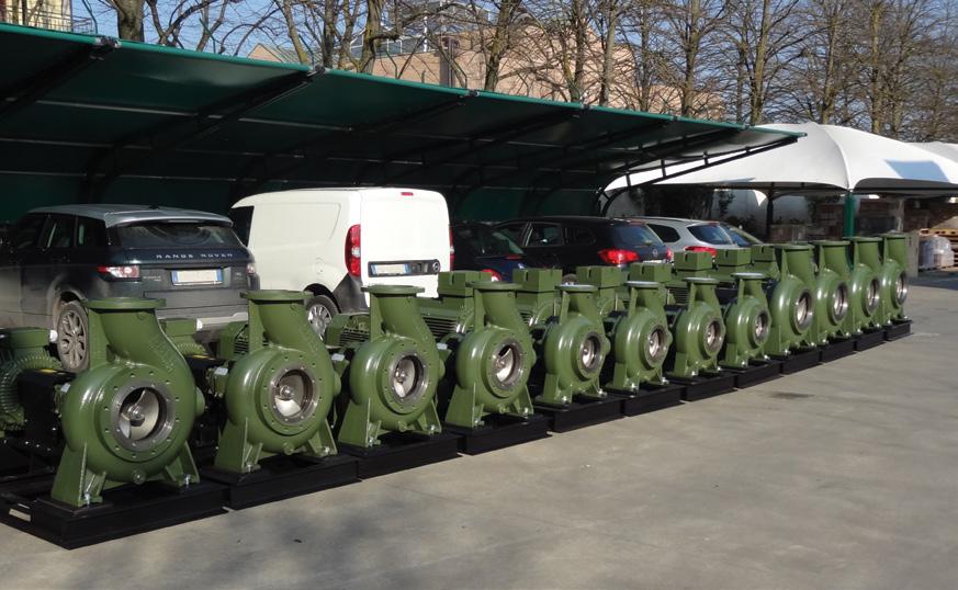
In order to address the needs of surface wastewater
pumping, the NCA range is the ideal answer. The range is continuously evolving and in the short-medium term is going to cover the following range:
• Flow = 20-2200m³/h
• Head = 5-65m
• Absorbed power = 4-200kW
• Outlets from DN65 till DN300
As one of SAER signature traits, the hydraulics is typically robust with centreline discharge to equalise foundation loadings and rigid feet for reduced vibration.
The robust bearing design is capable of withstanding maximum axial loads for long periods and the high strength stainless steel shaft provides continuous service.
The efficiency of the machines is high, combining energy savings with a wide free passage.
A special volute design reduces radial loads. Thanks to the back pull-out design configuration, maintenance is simple and there is replaceable wear plate on the suction side.
The pumps can be provided in different materials, the impeller can be either closed or open, and the seals can vary between soft packing, component mechanical seal, single or double cartridge seal with different flushing plans.
There are two types of bearings bracket for standard and heavy duty applications, with the choice of different lubrication systems.
Upon request, it is possible to get the pump with windows for inspection.

Climate change, population growth, and water scarcity are creating new challenges, and desalination is becoming an important alternative to traditional freshwater resources.


Industry Focus
Performance and Reliability in Water/ Wastewater
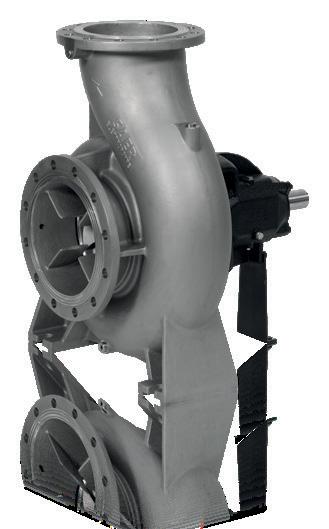
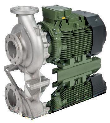
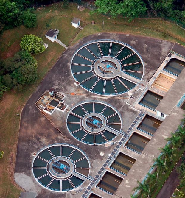
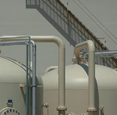
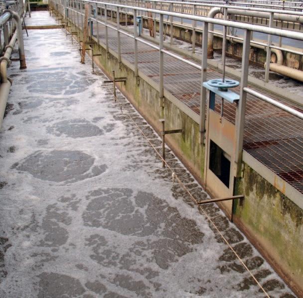
In processing raw sewage to high quality potable water, water treatment plants are exposed to erosion-corrosion, chemical attack and abrasion problems that result in increased operational costs.
Belzona® can provide a cost e ective solution to such maintenance problems by minimising downtime, labour and equipment replacement costs, whilst at the same time increasing the e ciency of the plant and ensuring environmental compliance in:
• Fluid handling equipment
• De-aerators, absorbers and process vessels
• Clarifiers
• Sludge de-watering
• Digesters
• Filtration
• Buildings & structures
• Mechanical damage to general equipment

www.belzona.com
Belzona® provides the solution to your repair and maintenance needs.

Additional Application
Areas Include:
Liquid Vacuum Pumps
•Rebuilding and protecting impellors and castings
•Auger and trough erosion protection
•Chutes and hoppers abrasion protection
Sedimentation Units
•Concrete repair and protection
•Sludge pump repair
•Expansion joints
Aeration Units
•Leaking pipes and nozzles
•Eroded fans and blowers
Chemical Treatment
•Tank lining
•Pump protection
Sludge Treatment
•Sludge pumps
•Dewatering units
•Hopper abrasion protection
Methane System
•Corrosion to scrubber vessel
•Leaking gas and water piping
•Erosion-corrosion in gas compressors
Fluid Handling Equipment
•Maintain pump e ciency
•Improve pump performance
•Repair and protect leaking pipes
•Flange face protection
•Repair and protection of valves
Water Treatment
•Deteriorated filters and strainers
•Chemical containment areas
For further detailed information refer to:
Belzona® Product Specification
Belzona® Instructions For Use
Belzona® KNOW-HOWIn Action
Contact Us:
Head Office: 03 8720 8600
Nth QLD - Michael Christian – 0477 003 410
Sth East, Central QLD and PNG - Andrew Petroff – 0425 863 004
NSW - Beau Dowton – 0427 070 252
VIC, TAS & NT - Trevor Comb – 0433 946 337
SA - Charlie Farrant – 0409 780 775
WA - Michael Dutton – 0430 294 334
Service
Through a global distribution network covering 120 countries, Belzona® can provide a full 24 hour on-site service with guidance and technical advice on the application of Belzona® products, available through the local Belzona® Consultant.
Experience
Since 1952 Belzona® has provided global expertise in the development and manufacture of innovative repair and protection solutions. Across a range of industries Belzona’s track record has gained the confidence of countless engineers, contractors and maintenance personnel throughout the world.
Technology
Reliability
Industry can count on Belzona® to provide a prompt response, whether it is an emergency repair or simply a routine maintenance issue.
Belzona® products are engineered to withstand the most aggressive environments such as erosion, corrosion, abrasion, chemical attack and mechanical damage, extending equipment life and improving e ciency.
People
From the chemists and engineers in the Belzona® centres, to the network of local Technical Consultants, each person is part of the Belzona® team, knowledgeable and trained in solving the problems of your specific industry.
NEW HIGH-TECH ROTARY LOBE PUMPS
Boerger has surprised the world of pumps with a new generation of its BLUEline rotary lobe pumps, the BLUEline Nova, with the high-tech pump available in six sizes and with flow rates of up to 110m³/h. The German manufacturer promises not only excellent volumetric efficiency but also maximum choice of sealing systems.
Boerger is well-known for its highquality rotary lobe pumps with flow rates of up to 1,450m³/h. Presenting the new generation of its BLUEline rotary lobe pumps, Alois Börger, Managing Director of Boerger, said, “The development of the BLUEline Nova has benefited from our 30 years of experience in pump manufacturing. With the help of computer flow simulations and physical test bench hours, we were able to improve the pumps even further.”
Mr Börger said the rotors and casing were made for one another. This newly developed one-piece DIUS rotor ensures an almost pulsation-free pumping at pressures of up to 12 bar, while the wide sealing surfaces of the screw-profile rotor prevents backflow of the medium.
“Boerger has also modified the pump chamber to utilise the dual-lobe rotor to its full potential. The geometry of the inlets and outlets, as well as the wrap angle of the casing, were
particularly optimised. We were able to considerably improve the volumetric efficiency of the pump. To this end, we have adjusted the pump chamber to the rotor geometry in a flow-optimised design,” Mr Börger said.
The BLUEline Nova comes in two variants: with or without protection plates and liners. In its clean version, protection plates and liners are not required. The pump with minimum dead space can be cleaned according to the hygiene procedures, CIP (Cleaning-InPlace) and SIP (Sterilisation-In-Place).
In its tough version, the pump is equipped with protection plates and liners for pumping abrasive media containing solids. With a new, innovative fastening system, the ‘tough’ version of the Nova pump ensures the best volumetric efficiency ever achieved in a rotary lobe pump. In case of wear, the protection plates and liners will be replaced quickly and easily due to its MIP® design (Maintenance in Place).
The large seal chamber of the BLUEline Nova provides space for different sealing systems, therefore ensuring connection of external supply systems is possible, and without issues. Different motors can also be selected for driving the BLUEline Nova rotary lobe pump. Upon request, the drive can be directly flanged to the pump and, due to the elimination of the coupling, the unit is now even more compact. In addition, this version does not require a base frame.
Like all Boerger pumps, the BLUEline Nova rotary lobe pumps can be manufactured according to the European ATEX guidelines for use in potentially explosive atmospheres. An API-676-compliant design, production according to the FDA regulations, or a technically tight pump design according to the German TA Luft requirements, round off the various options for versatile applications.
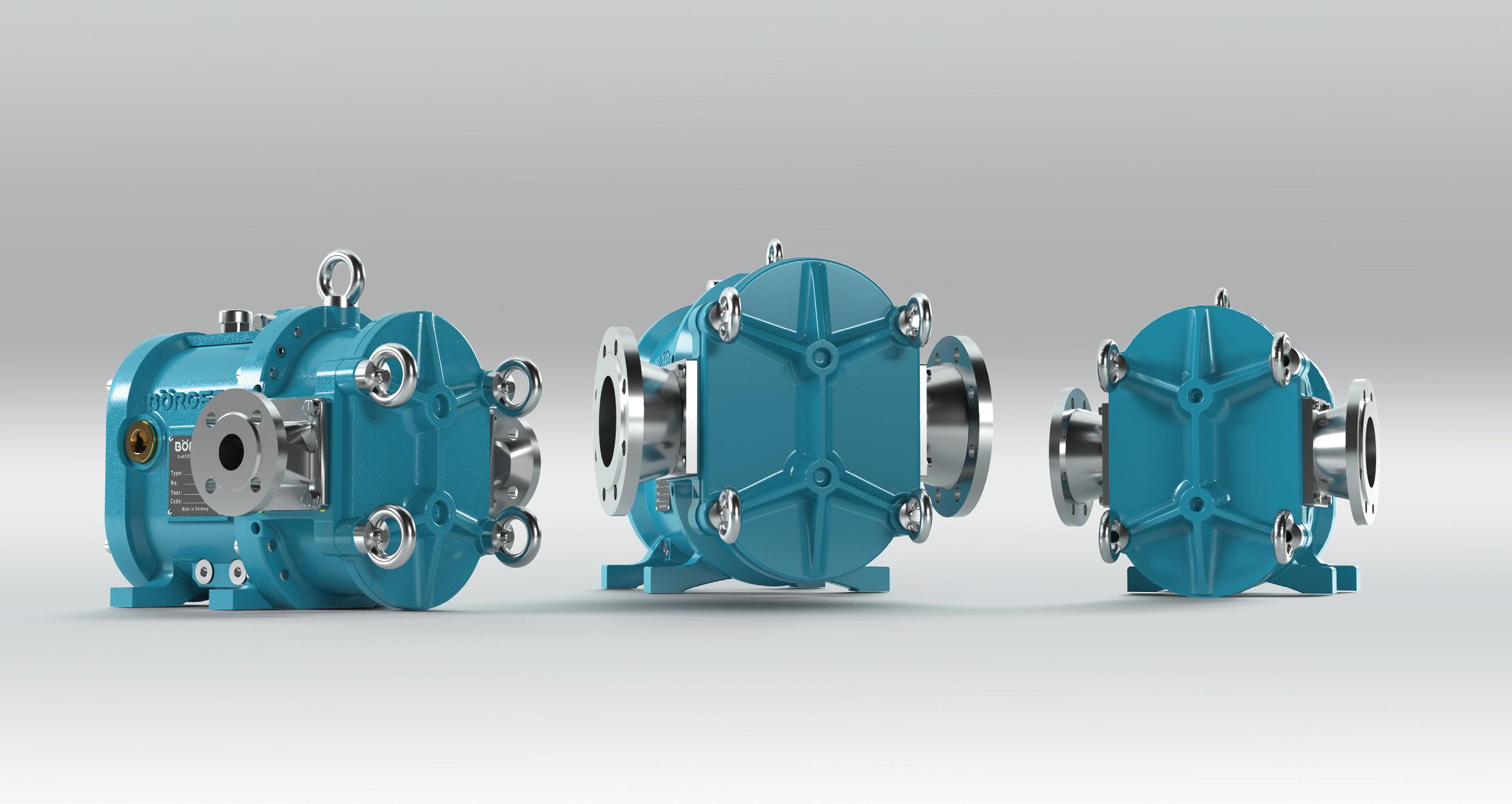
THE NEW BLUELINE NOVA ROTARY LOBE PUMP

The BLUEline Nova sets new standards in pump technology. With or without protection plates and liners – the BLUEline Nova achieves unrivaled volumetric efficiencies.
Made for one another – the newly developed DIUS rotors in combination with the flow-optimized pump chamber ensure perfectly smooth running at pressures of up to 12 bar.
Vogelsang launches new rotary lobe pumps for demanding media
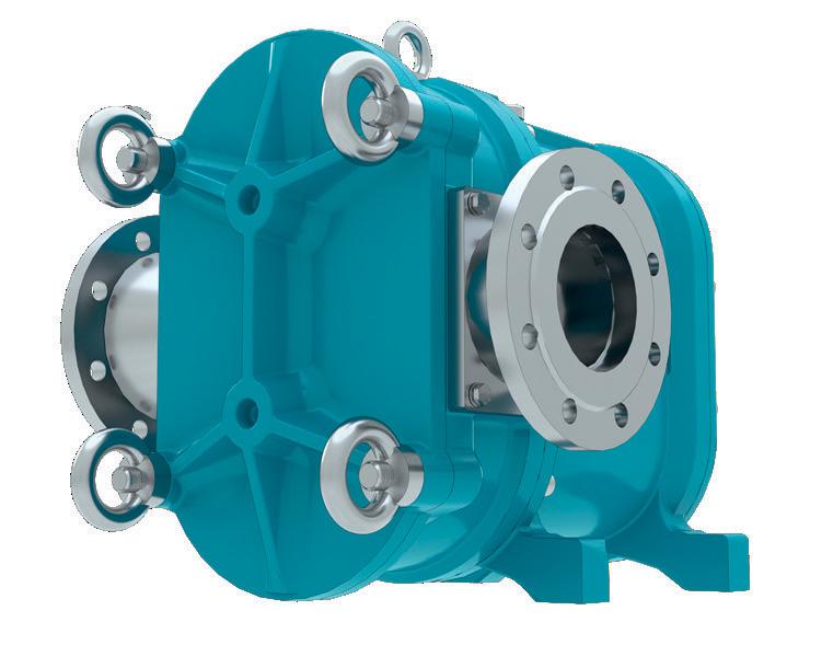
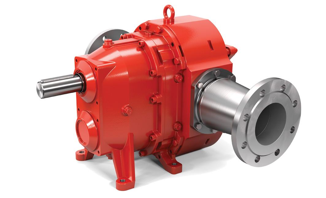
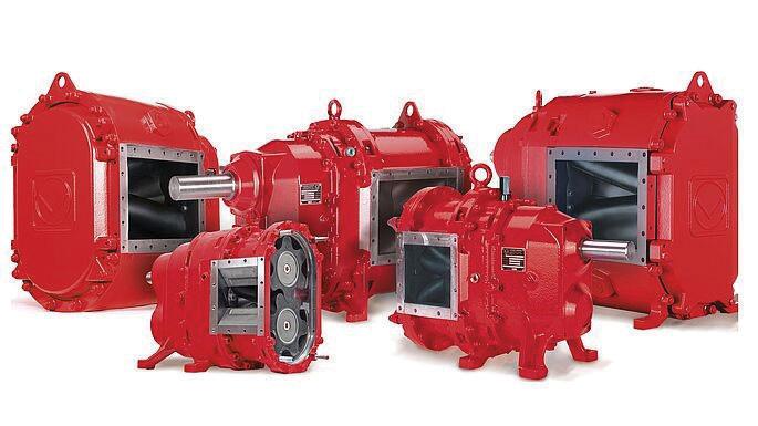
With its EP series and VY series, Vogelsang GmbH & Co. KG from Essen (Oldenburg), Germany, is launching two new pump series that meet the high demands of industrial use. The rotary lobe pumps are made of a flow-optimised one-piece housing and are therefore particularly efficient. They reliably convey thin-bodied as well as highly viscous, pure and solids-containing media at temperatures of up to 200°C. The pumps are ATEX and TA-Luft compliant and thus suited for use in highly demanding areas such as the oil, gas and chemical industries.
Thanks to increased efficiency and added seal versatility, Vogelsang is able to open up new areas of application for its proven pump technology. As the inventor of the elastomer-coated rotary lobe pump in 1970, Vogelsang has been for decades one of the world's leading companies in the field of pumps.
EP series: rotary lobe pumps with up to 18 bar pressure
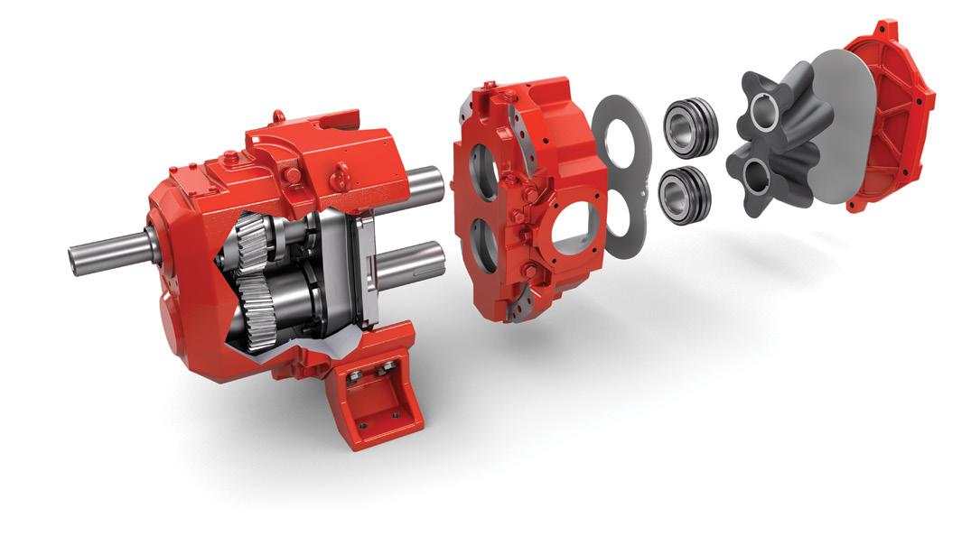
The EP series is designed for extreme conditions and permanently high pressures. Its high-performance gearbox allows for a constant pressure output of up to 18 bar, making it unique on the market today. The pumps of the EP series consist of a one-piece housing made from either cast iron or stainless steel. Helical gears in the gearbox ensure smooth performance and reduce noise emissions. Pulsation-free transferring reduces wear on the adjacent pipeline to a minimum. The high-pressure performance and temperature limit of 200°C, along with its seal versatility, make the EP series suitable for applications for which companies previously used screw, gear and progressing cavity pumps. These include the oil and gas sector, tank farms, the petrochemical industry, and the production of paints and varnishes, paper, glue and sugar.
Vogelsang has additionally equipped its EP series with an AirGap for increased operational reliability. This gap atmospherically separates the gearbox and the pump chamber, ensuring that in the event of a leak, liquid will drain out rather than entering the gearbox.
VY series: a highly efficient all-rounder
VY series rotary lobe pumps are based on Vogelsang's proven VX series. The versatility of the VY series makes it suitable for use in the chemical industry, as well as in the paper sector. The performance spectrum ranges from 1m³/h to
120m³/h at a maximum pressure of 10 bar. Integrated sensors provide all important information about the pump's operating status. The VY series is also available with axial and radial wear protection for media with abrasive components.
Seal versatility for increased flexibility
A variety of different sealing systems can be used in the housing of the new pump series depending on the industryspecific standard and requirement. In addition to the Vogelsang Quality-Cartridge, further special mechanical seals are available for the EP and VY series. Vogelsang worked with leading manufacturers to develop the CoX-Cartridge and offer the right solution for a variety of applications; from use in oil and sugar production, to conveying hot, chemically demanding media or latex paints. The seal's robust design also makes it suited for high-pressure use. The new pump series can also be equipped with mechanical seals according to API 682 if required.
The performance spectrum of the VY series ranges from 1m³/h to 120m³/h at a maximum pressure of 10 bar.
Service-friendly assembly and cleaning
For increased ease of service, both pump series feature a quick connection. Thanks to this, pipelines can be connected to pumps in a matter of minutes. The Quick-Service cover allows access to all internal components. Furthermore, when designing the EP and VY series pumps, the engineers placed significant importance on easy cleaning. The pumps can be rinsed and disinfected according to the CIP (Cleaning in Place) and SIP (Sterilisation in Place) cleaning procedures. The housing design also reduces dead space to a minimum, thus preventing liquids from accumulating in gaps or uneven surfaces.

KEY PRODUCTS REINTERPRETED
KEY PRODUCTS REINTERPRETED
For initial information, scan the QR code or visit: vogelsang.info/int/ industry-news

ENGINEERING FOR THE FUTURE
So you don’t want to wait for ACHEMA to provide your company with the best equipment? Then stop by for a virtual visit with us and be among the first to benefit from groundbreaking efficiency and cost-effectiveness.
So you don’t want to wait for ACHEMA to provide your company with the best equipment? Then stop by for a virtual visit with us and be among the first to benefit from groundbreaking efficiency and cost-effectiveness.
In everything we do, we never lose sight of what is essential to you: economical work with innovative and reliable technology.
Gas, oil, chemical products, paints, and coatings – Vogelsang is seen throughout the world as a technology leader, and with its highly efficient and durable pumps, the company has long since proven itself in these industrial sectors as well.
Gas, oil, chemical products, paints, and coatings – Vogelsang is seen throughout the world as a technology leader, and with its highly efficient and durable pumps, the company has long since proven itself in these industrial sectors as well.
As the inventor of the elastomer-coated rotary lobe pump and innovation driver in the field of pumping, and grinding technology, Vogelsang has been one of the world’s leading mechanical engineering companies for decades.
Nevertheless, the more elaborate and automated the process, the greater the demands on the machines. That’s why we’re introducing a new generation of pumps and equipment options for you in 2022 to support your efforts to lead your company into the future.
Nevertheless, the more elaborate and automated the process, the greater the demands on the machines. That’s why we’re introducing a new generation of pumps and equipment options for you in 2022 to support your efforts to lead your company into the future.
Thanks to our extensive know-how and many years of experience in various sectors, we use technology at an environmental level in order to be a competent partner for our customers. In fact, in addition to our powerful and easy to use machines, we offer an efficient pre and post sales consultancy service to always guarantee the best solution for each single application, and its perfect maintenance over time. Among other things, with powerful and servicefriendly technology.
You can rely on competent and personal advice and reliable service.
VOGELSANG – LEADING IN TECHNOLOGY
vogelsang.info
VOGELSANG – LEADING IN TECHNOLOGY vogelsang.info


EFFICIENT
VOLUME
WITH VAUGHAN ROTAMIX
Vaughan’s Rotamix system sets itself apart from the competition with no moving parts in the tank, removing the need to empty a tank for service and maintenance of the mixing system by keeping serviceable components out the tank or digester, and ensuring reliability and efficiency for wastewater treatment plants across Australia.
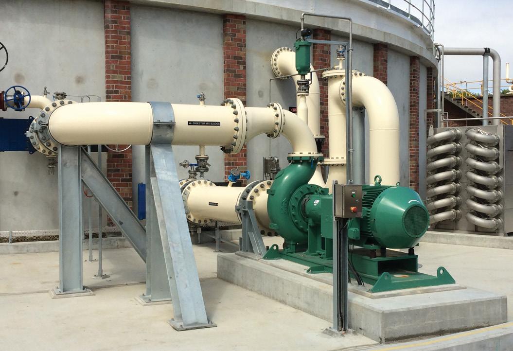
Vaughan’s Rotamix system is second to none when it comes to mixing large volumes! Municipal wastewater treatment plants across Australia now insist on Vaughan Rotamix, with plant operators commonly saying “the Rotamix system is not the squeaky wheel on site, it just works”.
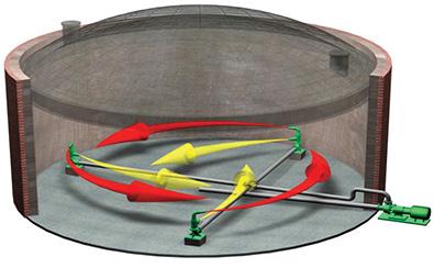
The Rotamix System is a series of fixed-floor and wallmounted nozzles inside a tank or digester that induce mixing energy to the tank volume. The heart of the system is a Vaughan chopper pump. This extreme duty pump supplies flow to the nozzles, condition media, and prevents blockages.
So how does reliability ensure efficiency? By establishing and maintaining active volume mixing. A great deal of energy is expended to achieve active volume mixing from a stand-still, and it is more efficient to continuously maintain mixing than to re-start following a failure.
Further efficiencies are achieved in two ways:
1. Rotamix is paired with a Variable Frequency Drive. For a typical system, mixing energy can be reduced periodically throughout the day, resulting in energy savings
2. Biogas generation rates increase when solids are continuously conditioned and fully suspended within the tank volume, allowing organisms easy access to the volatile solids they feed on. This gas can be used to generate electricity and thus subsidise plant energy requirements
Designed and configured for each individual application
Each Rotamix system is unique, designed and configured for the sludge rheology, tank geometry, and local process considerations of each individual site.
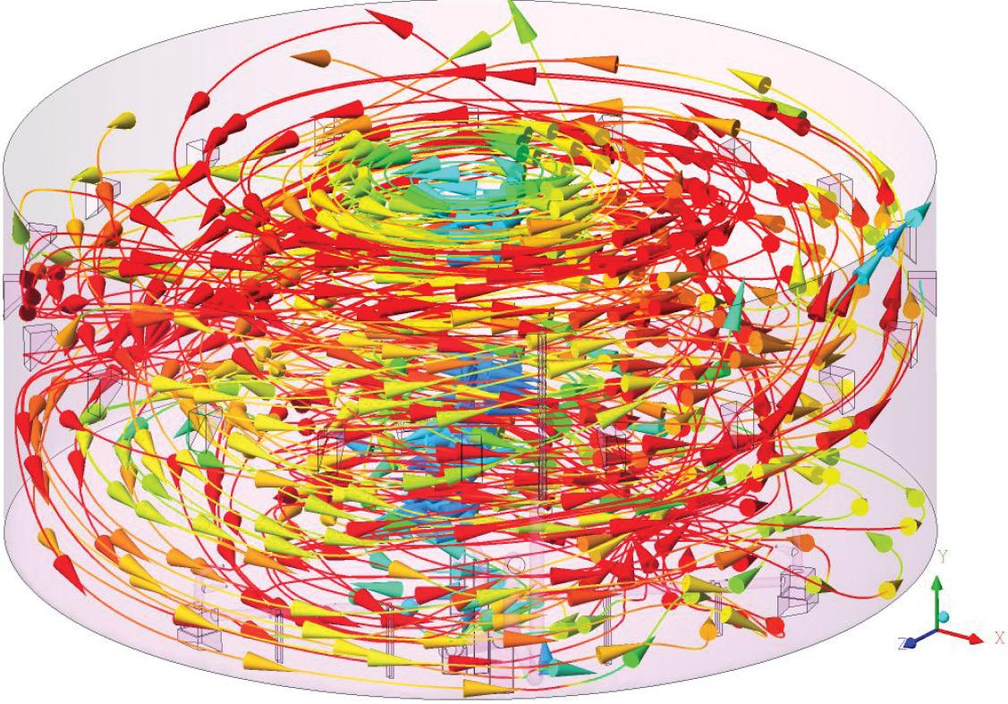
Vaughan uses state-of-the-art Computational Fluid Dynamics (CFD) modelling to design each system that can accurately model not just the tank geometry, but also piping and other obstructions to ensure proper mixing.
The Rotamix system incorporates several basic principles of physics and hydraulics including uniform field of flow, vortical field of flow, induced flow, surface contact, and Dual-Zone Mixing which ensures even mixing velocity across the entire cross-section of the tank. The result is a homogenous volume, an even distribution of solids, and a constant temperature.
In digester applications, foaming can be a major operational challenge. To complement the Rotamix system, Vaughan has developed the Foambuster mixing assembly, which can be added to any Rotamix system or provided as a standalone system.
The Foambuster uses a splash-plate to produce a field of droplets which suppress foaming at the surface before it can interfere with process operation.
To date, there are 65 Rotamix systems at wastewater treatment plants across Australia and New Zealand, with more in the planning stages.
Vaughan Chopper Pumps and Rotamix Systems for Australasia are supplied by Pump Systems Pty Ltd in Australia, and Pump Systems Ltd in New Zealand. Further details are available from their website www.chopperpumps.com.au, or freephone 1 800 121 452.

ANGUS WELLMASTER FLEXIBLE RISER:
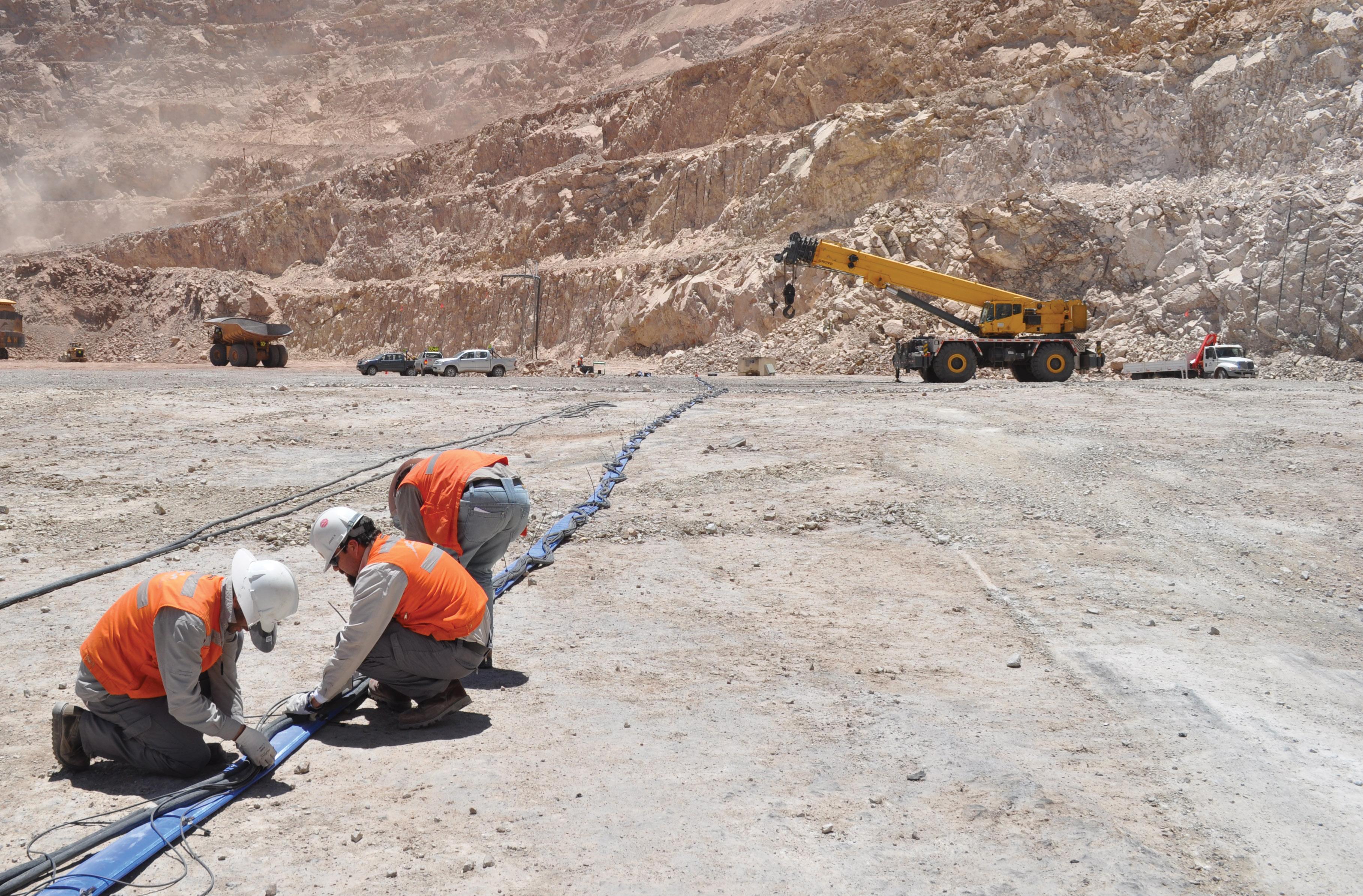
Angus Flexible Pipelines Australia (AFPA) is a leader in providing water transfer solutions to a wide range of industries including mining, agriculture, military, ship to shore, oil and gas, and many more.
At the heart of these solutions is the Angus Wellmaster layflat hose, which has been instrumental in the successful running of numerous operations in the harshest and most challenging environments.
Angus has been producing layflat hose for more than 220 years and the company’s ethos of continuous improvement has developed the range of high-performance hoses that now service operations in over 100 countries worldwide.
Angus Wellmaster layflat riser has been developed for deeper boreholes, offering greater pump setting depths –320m (as deep as the tallest building in Australia) – and designed for use with electric submersible pumps for all types of groundwater borehole extraction, well monitoring operations and mine dewatering.
Benefits
Apart from the major cost savings and performance advantages over conventional rigid and polyethylene pipes, every metre of Angus Wellmaster flexible riser undergoes over 24 individual tests before it leaves our factory. This gives our customers
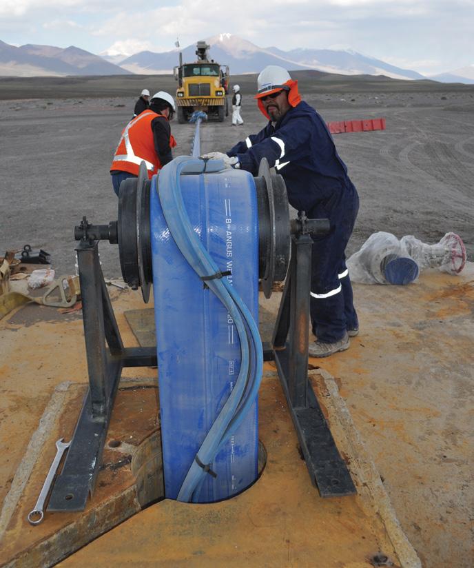
the reassurance of its unrelenting performance and being a flexible riser, it deploys in the field with ease and can be quickly maintained on a regular basis with little interruption of service. Added to this, Wellmaster is extremely
adaptable and is able to negotiate the most unforgiving terrain.
With worldwide potable water approvals and total corrosion, microbiological and internal scaling resistance; all this has helped make Angus Wellmaster the highest performing global flexible riser main.
Wellmaster range
Angus Wellmaster layflat hose is available in a variety of lengths WM150, WM250 and WM400, and diameters (32mm-208mm) to cover all possible pressure needs and performance requirements.
Immediate delivery
From our facilities in Queensland and Western Australia, we can supply all operations across Australia with stock of all lengths and diameters for immediate delivery; and with couplings to fit the range, AFPA can cater for all your mine dewatering needs.

ROTO PUMPS – MOST ADMIRED COMPANY FOR CUSTOMISED AND TECHNICALLY
SUPERIOR HELICAL ROTOR PUMPS FOR THE MINING INDUSTRY
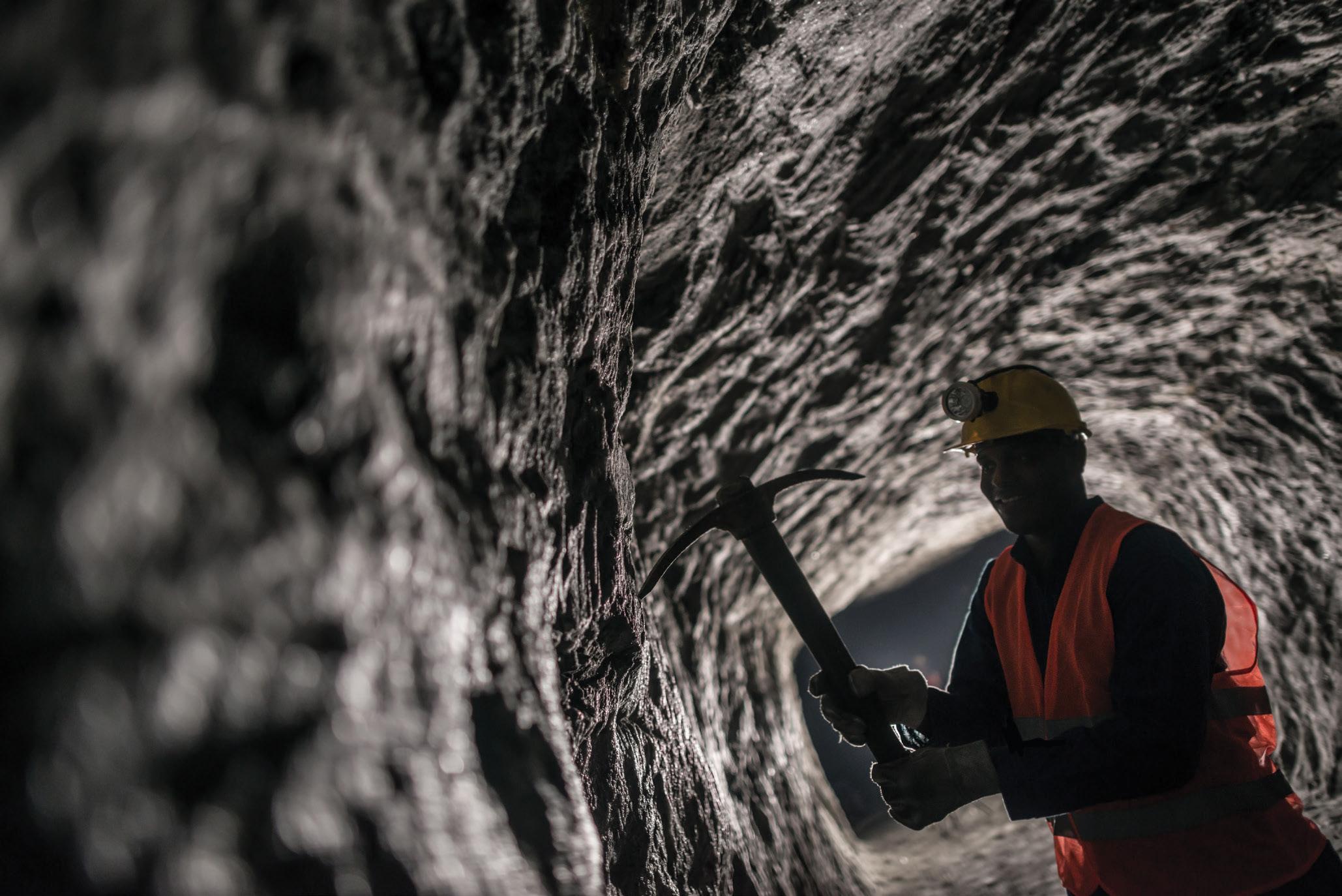
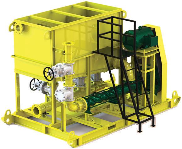
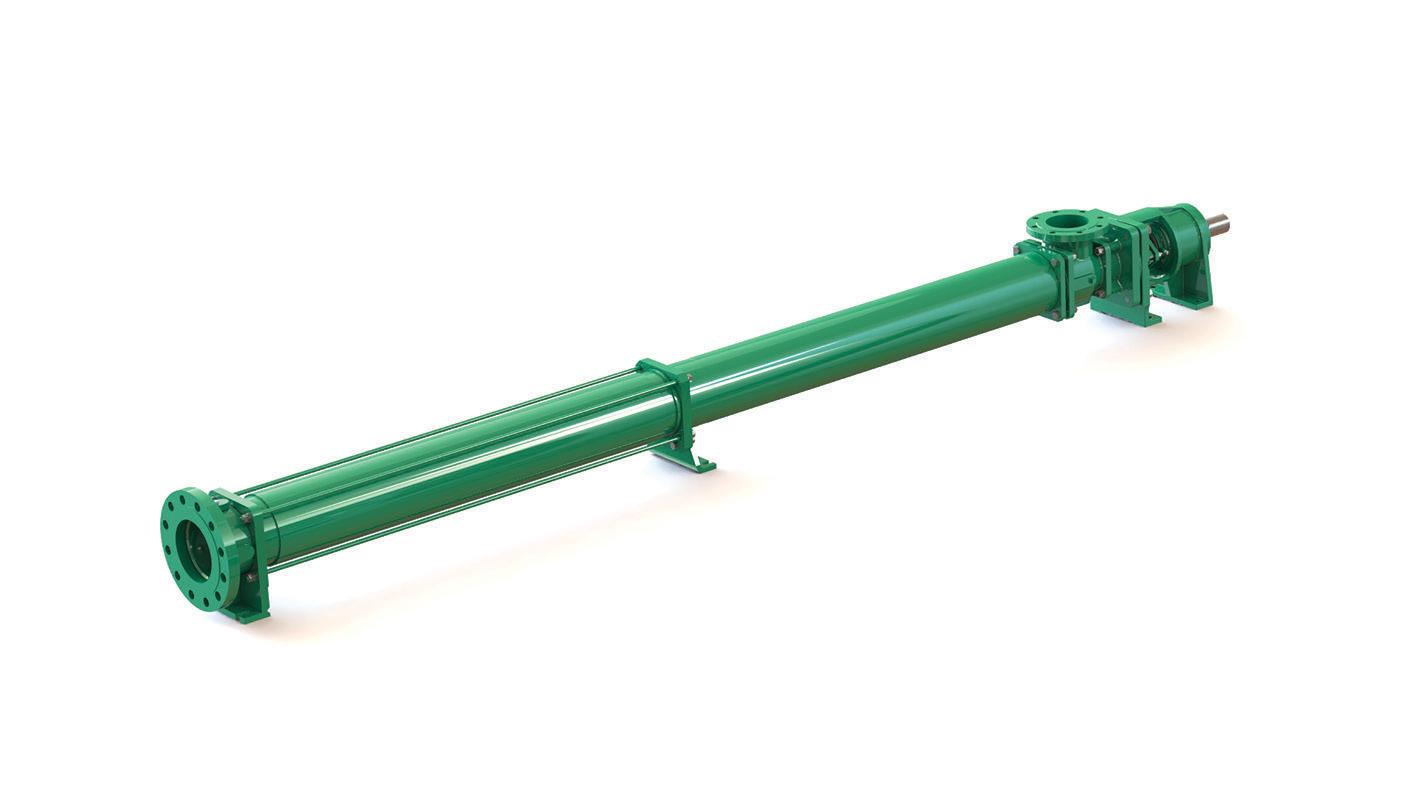
We at Roto Pumps started our journey by supplying our very first pumps to the mining industry. As a user-turned manufacturer, we have always understood the major challenges faced by the mining industry. This led us to carefully design and develop advanced helical rotor pumping technology to meet the challenging demands of the industry.
Roto has provided helical rotor pumps to all types of mines i.e. underground, open surface, placer and in-situ mines for the last 53+ years. In modern times, the major challenges that are faced by mining companies are:
• High wear and tear in elastomeric stators and rotors
• Reduced pump performance due to the use of rechromed rotors
• Low lifecycle of pumps and spares
• Reducing recurring pump, spare and operation costs
• Need for prompt service and support
• Regular requirement of readily available pumps and spares Since it has been associated with mining from its early days, Roto has evolved and invested in its manufacturing practices to stay ahead of the competition while meeting the global mining industry demands. Roto Pumps has developed a complete range of helical rotor pumps for the mining industry, solving critical media pumping challenges and successfully handling all the major applications in mining and explosive industry such as:
• Cement grout/grout mix
• Clay and mineral slurries
• Coal water mixtures
• Dirty water
• Explosive mix transfer and filling
• High pressure wash
• Gland service
• Mine dewatering
• Mineral processing
• Mortar with fine oily water
• Oily water transfer
• Rock dust slurry
• Water spray for dust suppression
• Gace dewatering and high head dewatering
Built for a long lifecycle
Roto has an advanced manufacturing plant for developing a wide range of
helical rotor pumps and spares. It has six strategic overseas establishments with large assembly and warehouse infrastructures. These establishments are backed by strong localised sales teams to provide readily available pumps and spares, and prompt service support.
Roto has developed a unique rotorstator geometry that ensures low rubbing velocities between rotor and stator; eventually leading to an increased rotor and stator lifecycle. This also helps in providing consistent flow at varying pressures.
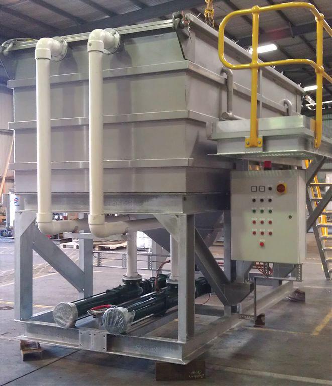
Roto’s specially designed two-pin joint (Cardan universal joint) provides flexibility in operating the pump in both directions. These joints are designed to have more angular movement which reduces the overall footprint of the pump, thus making it more compact. Also, these two pin joints can easily withstand loads caused by pumping at high discharge pressures.
Roto ensures strict in-house process control and stringent quality checks for designing and manufacturing of the high-quality energy efficient pumps and spares (including spares for other brands) having a long lifecycle and less operational costs.
Stators to withstand harsh mining operations
Over the years, Roto has mastered the art of providing highly efficient elastomeric stators in a wide range of materials having high dimensional accuracies. These stators remain highly abrasion-resistant for a longer period of life compared to other stators available in the market. This is achieved by continuously focusing on in-house compound formulation and preparation, and mould design and manufacturing of elastomeric stators. We also have an in-house polymer test lab where it runs various tests on stators.
The rotor is the lifeline of helical rotor pumps. In mining, rotors are subjected to very high abrasion; thus most mining companies prefer hard chrome plated metallic rotors for longer life. Over a period, the high abrasion leads to faster wear out of the rotor, thus affecting the life of the pump.
Presently, many mining companies send these worn out rotors to local hard chrome plate companies to remove the chrome, rebuild and re-chrome the rotor. If they fail to ensure the correct dimensional accuracies (on major and minor diameters) between rotor and stator as per the original design, this eventually results in faster wear turnout of both parts, damaging the whole pump and reducing the overall pump lifecycle. So, in many cases, it is better advised to order a new hard chrome plated rotor knowing it will be to correct dimensional tolerances. Roto can provide rotors in a varied range of materials, including exotic materials, to ensure optimal life of the component.
Mining is one industry Roto knows well and it will continue to strive to develop technically superior products resulting in smooth and reliable pumping operation in order to provide peace of mind to our mining customers.


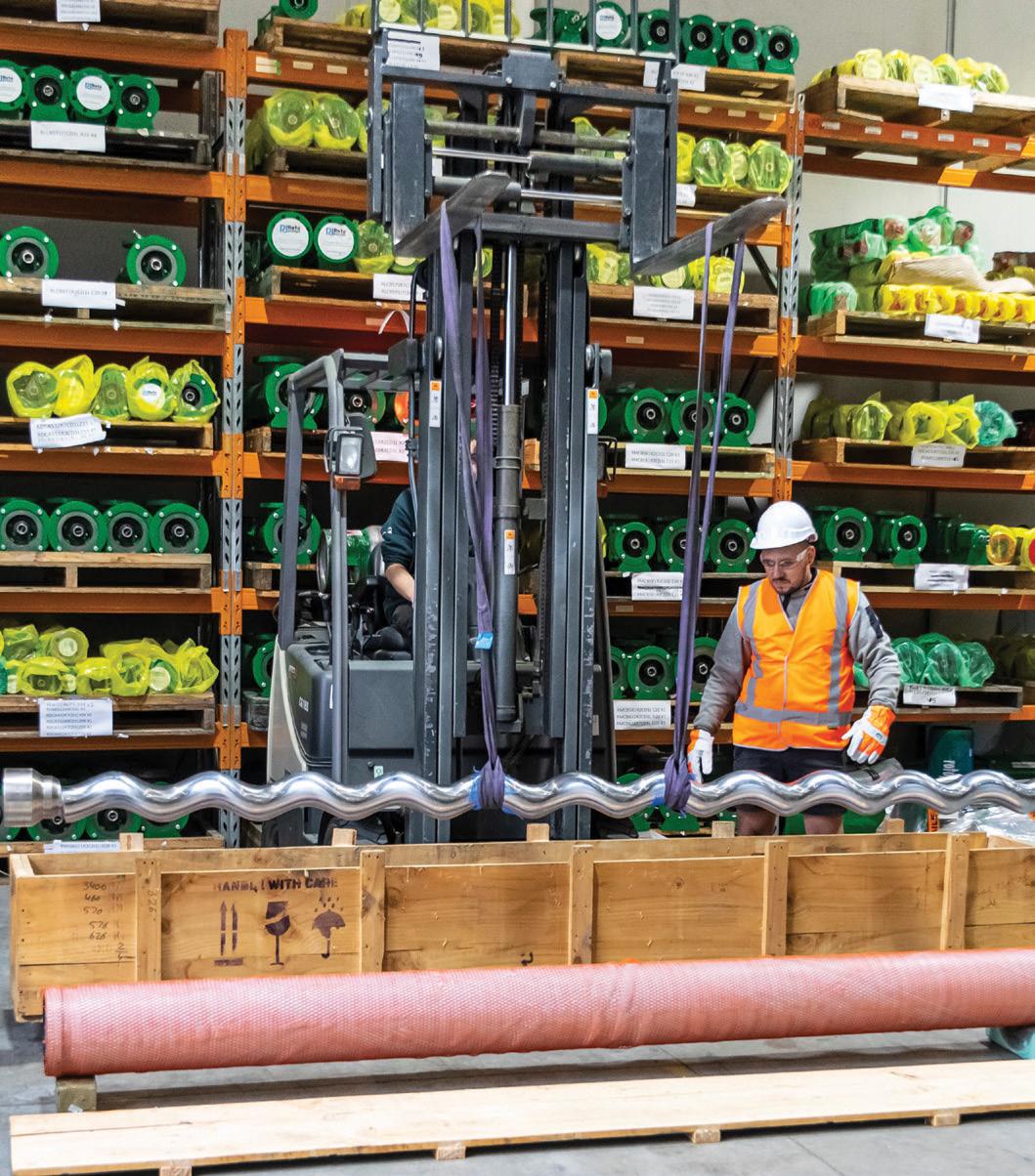
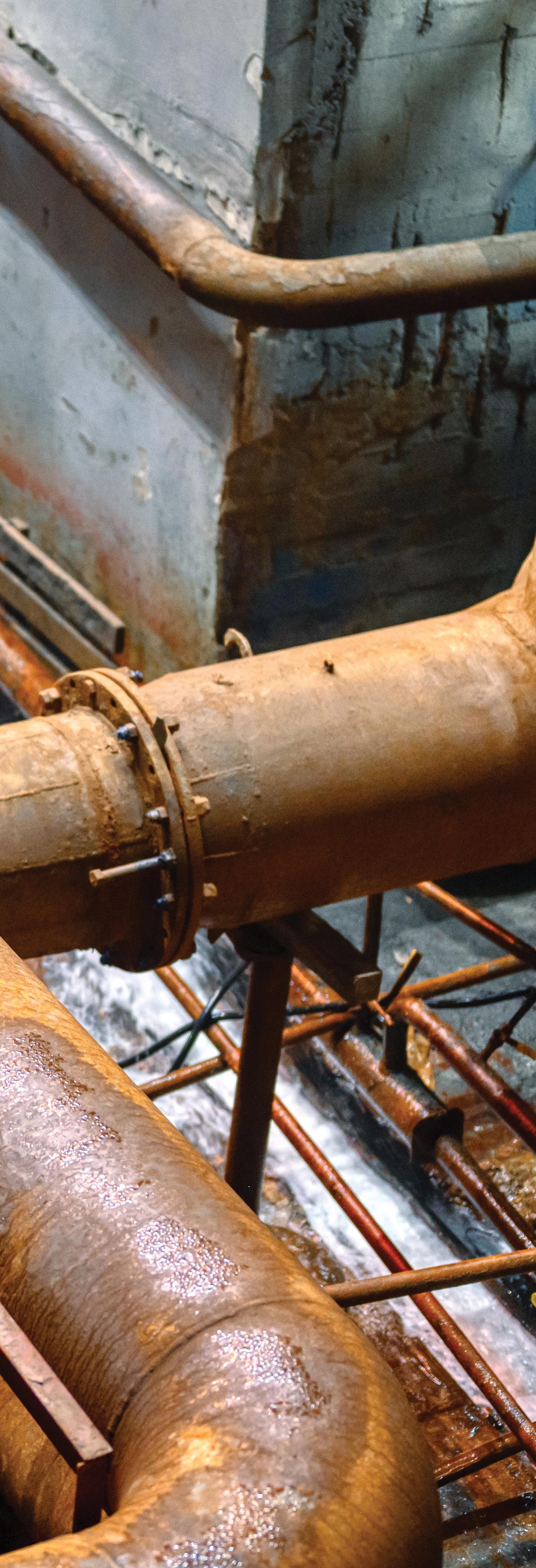
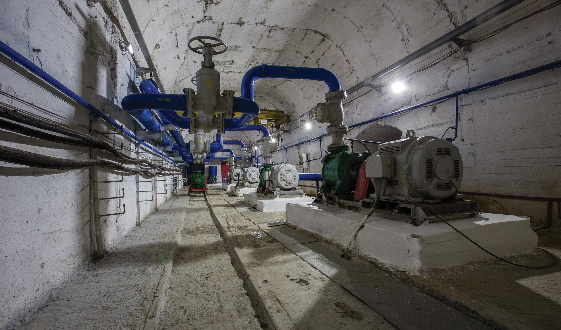
Benefits of ELECTRICAL VS DIESEL DRIVEN PUMPS in mining applications
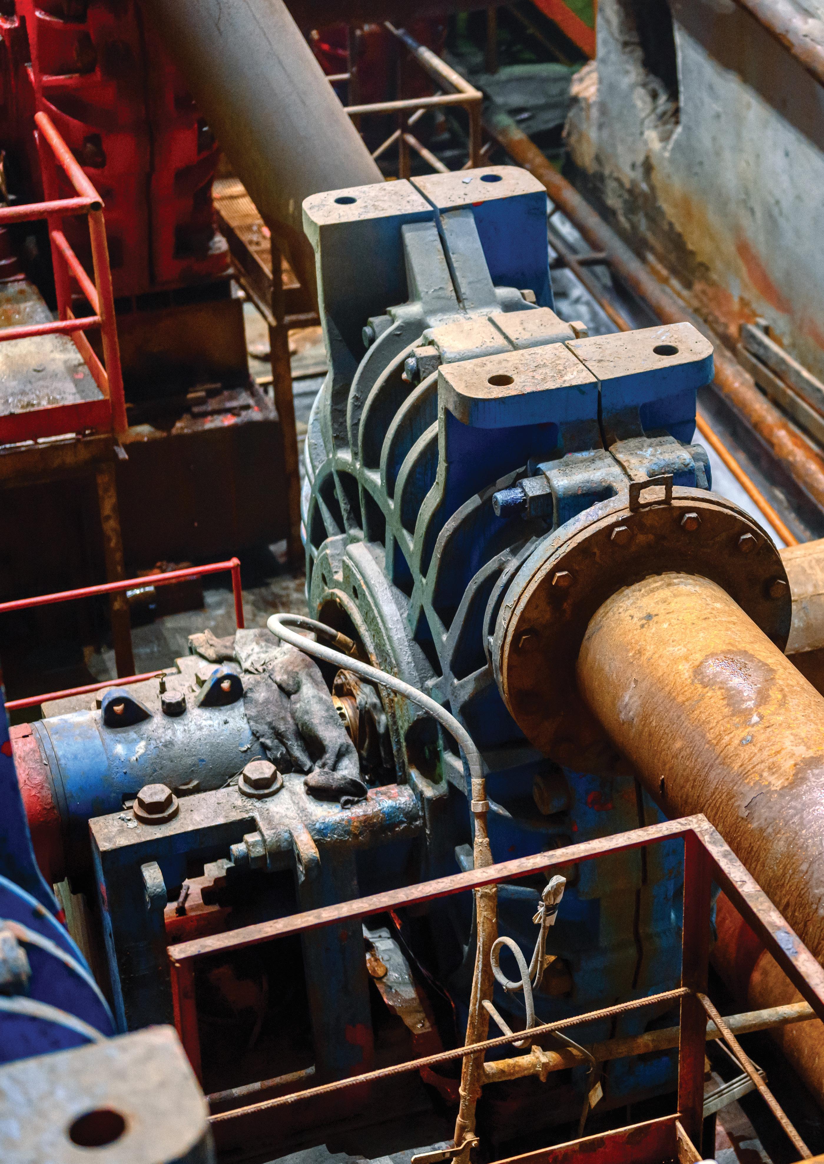
There are a wide range of applications in the mining sector that require pumps, including raw water supply, dewatering, transporting slurry and tailings, leach and drainage solutions, chemical dosing, transporting process water, truck washing, and dust suppression. Choosing the right pump for these applications is essential to ensure efficient and reliable operations, cost effectiveness, and safety for the workers and environment. Broadly, there are two categories of pumps that can be used, diesel-driven and electric-driven, and it is important to know which type is suitable for a particular application.
Traditionally, mining operations have relied on dieseldriven pumps due to the remote location of mine sites and the flexibility of easily moving the equipment around, amongst other reasons. And while they continue to be a popular choice, electric-driven pumps are starting to be accepted as a versatile choice that offers environmental benefits and are cheaper to run with increasing prices for diesel.
Electric-driven pumps
Applications
Electric-driven pumps are ideal where continuous operation is required on-site. As long as they can remain connected to a stable, continuous power supply, they can run continuously without damage or failure. This feature means they are the first choice for applications that need to operate for more than 20 minutes per cycle, such as dewatering and industrial processes.
These pumps are portable, easy to handle, and can offer a small site footprint, making them suited to groundwater applications. They are also useful in applications where diesel pumps cannot be used, such as in underground mines, where emissions are not allowed and at high altitudes.
Power and flow
Electric-driven pumps are available in a variety of performances and can generally handle higher flow rates and head than diesel-driven pumps. For example, medium-tolarge electric submersible pumps typically have a power rating up to 80kW and manage flows up to 20,000L per minute with a head of 85m.
Wide operating range
Electric-driven pumps are very versatile, making them a good choice for mine sites as they can adapt to the everchanging needs of the site. For example, when paired with a variable frequency drive (VFD) the speed can be adjusted so that it can be used for multiple applications, meeting varying duty points to achieve the efficiency and performance specifications of each application. VFDs also allow electricdriven pumps to operate over a larger operating range on the performance curve.
Environmentally friendly and safe
With ESG integration becoming a focus in mine sites over recent years, along with concern about global warming and more stringent environmental regulations, electricdriven pumps provide a cleaner and more environmentally friendly option.
Diesel-driven pumps produce greenhouse gas emissions from burning fossil fuels, and spontaneous combustion from non-exhaust emissions and leaks are safety and environmental concerns. Spillages of fuel not only cause harm to flora, fauna and the environment, but it is also a safety hazard and can result in costly cleanup.
On the other hand, electric-drive pumps – especially those powered by solar, wind or other renewable energy sources –have a much lower environmental impact and eliminate the risk of fuel spillages.
Ease of maintenance
Electric-driven pumps can be extremely durable, with high wear resistance. These parts tend to be easy to maintain, for example, submersible pumps with their modular construction allow for simplified maintenance procedures,
with some models also offering on-site servicing and parts replacement kits.
When paired with advanced controllers with data monitoring capabilities, the end user will be notified when service intervention is required, allowing for preventative maintenance without additional labour to manually check the pump.
Diesel-driven pumps
Applications
Diesel-driven pumps are designed to handle high volumes of water discharge, with discharge diameters for centrifugal pumps typically ranging from 75-200mm. They can work with clean or dirty water, as well as handle trash and fibrous materials. When designed with features such as semi-open impellers and an abrasion-resistant pump casing, submersible diesel pumps can handle solids up to 76mm in size. This makes them ideal for transporting or raising water with large abrasion solids such as for quarry site dewatering and floodwater.
Fully automatic, self-priming diesel centrifugal pumps are the choice for fast dewatering solutions on sites where there is no other power source available.
Their transportation and storage handling at remote sites is also made easier if they are equipped with forklift slots and a lifting eye.
Some pumps can also be equipped with an extra-large fuel tank to allow them to run for longer periods of time, reducing interruptions to work in order to refuel.
Diesel-driven pumps are not suitable for use in high altitudes as it negatively affects performance and efficiency due to the lower pressure. Furthermore, as the oxygen levels thin, a wider throttle opening would be needed to pull in an adequate amount of air, resulting in more fuel being burned.
They should also be avoided being used in areas where there is a high risk that the fuel could spark an explosion, or where a spillage could harm wildlife or contaminate drinking water.
Flow and power
These pumps have a typical operating flow between 50-830m³/h, with a head of up to 51m. They are also able to operate in a variable speed range, allowing them to cover different applications and flow/head combinations.
Maintenance
Diesel-driven pumps are built for endurance and reliability. Compared to electric-driven pumps, they require more frequent maintenance, and operations need to be interrupted for refueling, which delays work and increases the final cost. However, new techniques have reduced the amount of maintenance required, with oil and filter changes only needed every 250-300 hours and they can run without maintenance up to 1,500 hours and still have factory warranty.
Selecting a pump
Both diesel and electric-driven pumps have benefits for mine sites depending on the specific site requirements. While electric-driven pumps have a cost benefit across the lifecycle of the pump in terms of maintenance and fuel, diesel-driven pumps remain the better choice in a number of circumstances.
One of the key determining factors of which type to choose, is the operating conditions. If there is no access to power on-site, diesel-powered pumps are likely to be the better option due to the additional cost of needing a generator. Furthermore, if on-site power is not available across the mine site to allow an electric-driven pump to be used in multiple areas or applications, it may not be as cost-effective as a diesel-driven pump.
Diesel-driven pumps are also a good choice where it will be used across a site for temporary applications as installing permanent power to all the locations of temporary jobs within a site or sites is not a cost-effective solution.
However, where there is on-site power and it is costeffective, electric-driven pumps can provide a better return on investment, as well as a more environmentally-friendly and safer option for mine operations.

Grinder and Cutter Pumps
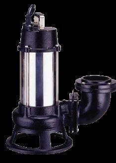
Maxijet has a diverse range of durable and cost effective grinder and cutter pumps for all your residential and industrial applications.
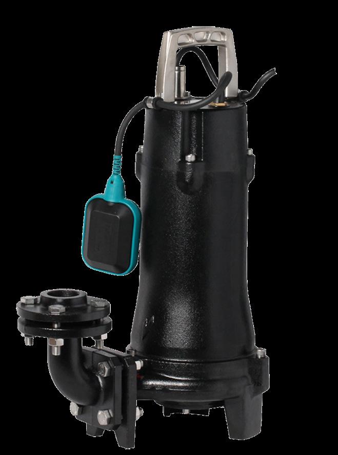
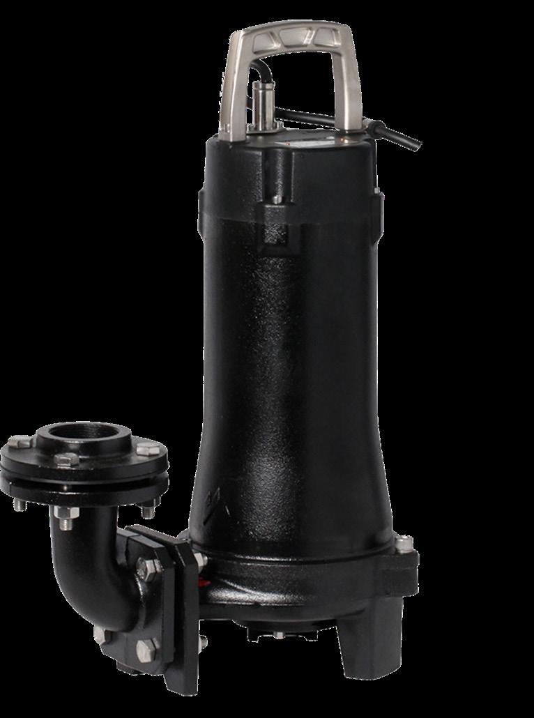
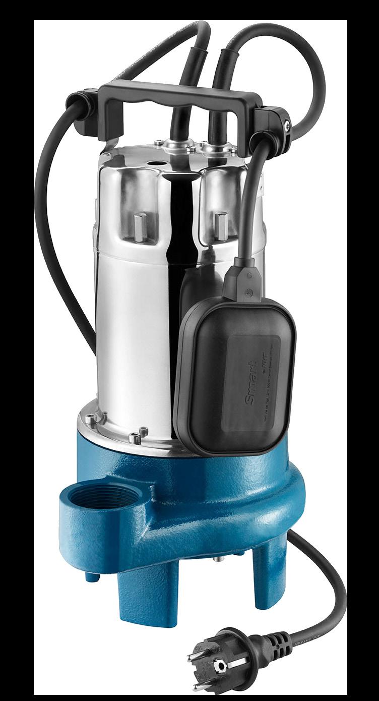
Maxijet is driven to be the industries most trusted source in customer service, technical, aftermarket support and industry solutions for the conservation of our most important global resource. We pride ourselves on being the industry people who care.
For more information on our Grinder and Cutter Pumps and expert advice to help you choose the right solution for your project, contact us today!



WORKING TOWARDS MORE EFFICIENT SLURRY OPERATIONS
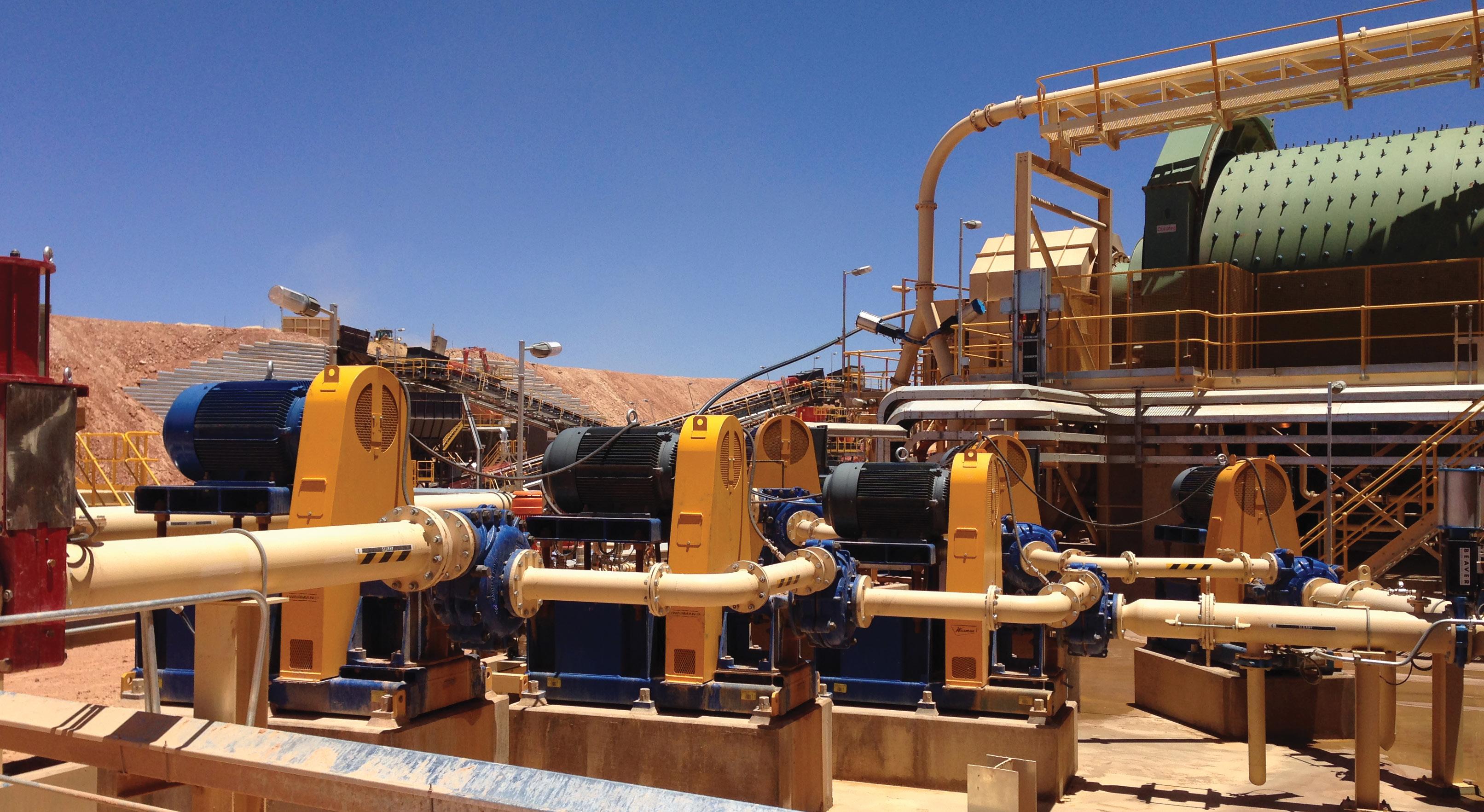
Slurry pumps are the workhorses of mining operations, helping to efficiently transport ore in the form of slurry throughout the site. Unfortunately, they are also often one of the more trouble-prone parts of most plants, with the abrasive nature of mining slurries taking a high toll on pump components.
A particular stress point is the gland area, where mechanical seals or packing are used to prevent leakage. Sealing solutions that are of poor quality or that are ill-suited to the application at hand can greatly increase maintenance demands, and lead to unplanned stoppages and excessive water use.
So, how can mining operators optimise the performance of their slurry pumps and improve the productivity and profitability of their plants?
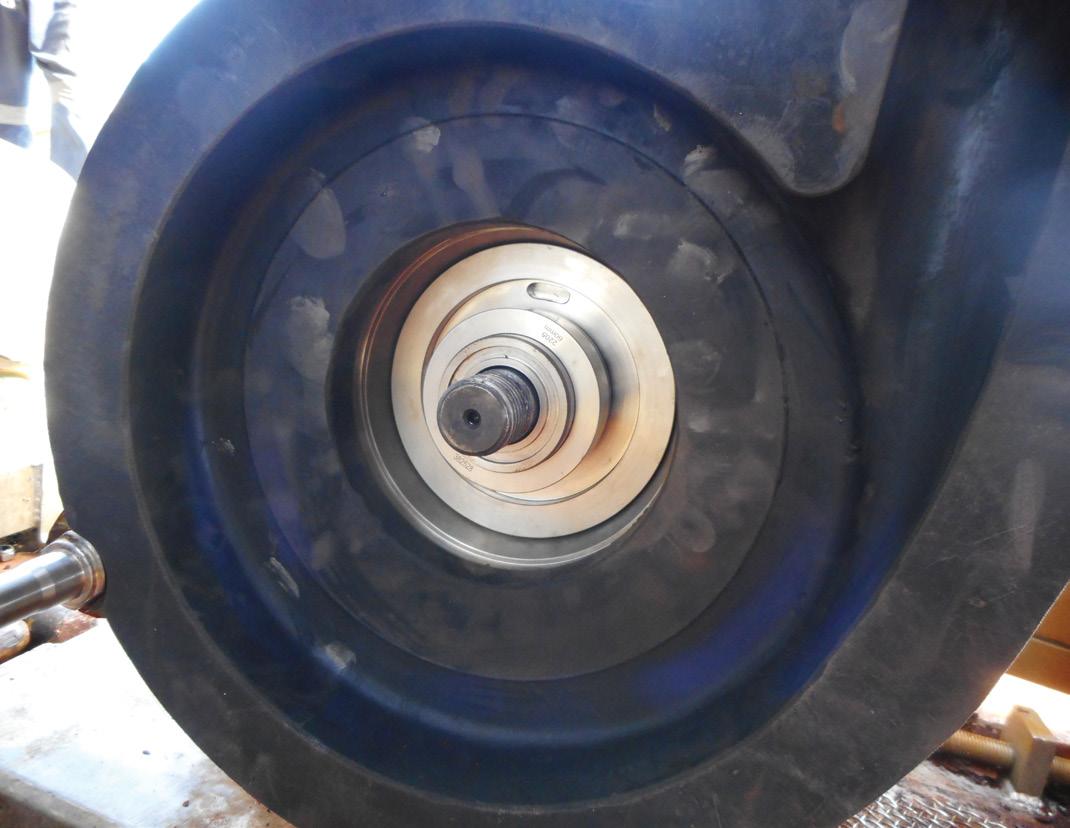
The first step is to understand the challenges that gland sealing solutions face and the requirements needed for success in the operating conditions present. The next is to understand how to choose either an efficient mechanical seal or high-quality packing that suits the application.
Understanding the challenges
One key consideration looking for a gland sealing solution is the hardness and abrasiveness of the slurry. Is the material being transported sharp and abrasive or round and soft? The Mohs scale of mineral hardness – which ranges from talc at one extreme to diamond on the other – can be used in the assessment. Naturally, the further down the processing order of operations a slurry is used, the rounder the particles are likely to be. While such particles are less abrasive, very fine particles can be problematic in that they may damage the small gaps between pump and seal components, such as between the seal faces. Not every pump in a process will be subject to the same levels of abrasion. Hence, pump OEMs have become very adept at maximising wear life through the use of different liner and impeller materials, ranging from extremely hard high-chrome irons to resilient rubbers and polyurethanes.
Another key factor is the nature of the slurry. The amount and weight of solids being carried in the slurry will have implications on wear. A mining slurry that is 35 per cent solids will be far more abrasive than one that is five per cent solids. Heavy mineral slurries also behave very differently to lighter fibrous slurries, which tend to absorb a lot of water and can potentially starve seal faces of the necessary lubrication. Care should be exercised to ensure that seal faces are adequately lubricated at all times, with particular attention paid to the temperature of the slurry and the rotational speed of the pump.
Often, the only available water to transport the slurry is hypersaline groundwater. This, along with high temperatures and chemicals that may be present as a result of the chemical extraction process, present yet another level of complexity that needs to be considered during seal selection.
Armed with this information, operators can make a more informed choice about whether to employ packing or a mechanical seal. If a mechanical seal is chosen, fine tuning of its design to improve the abrasion resistance can be
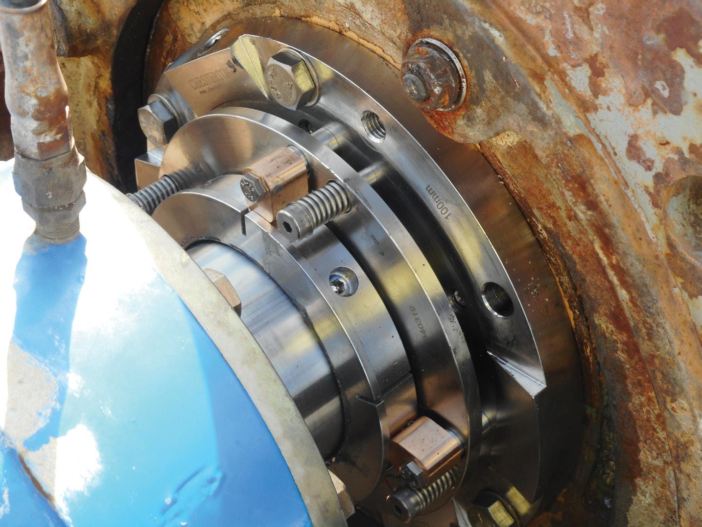
undertaken using items such as polyurethane covers, which enhance component life.
Choosing a mechanical seal
Mechanical seals are widely used in some mining settings, but still relatively uncommon in others. Among the applications with the greatest uptake are nickel, copper, alumina and mineral sand mining operations. Adoption is slower within gold, coal and iron ore. While usage is varied, mechanical seals have the potential to bring enormous efficiency benefits in terms of both equipment uptime and reduced water usage to all types of mining operations, provided a quality seal is chosen and properly installed.
So, what factors should be considered when choosing a mechanical seal? It’s important to remember that the mechanical seal faces will be lubricated by process water, which can often be dirty/salty/hot/acidic or alkaline. For this reason, slurry seal faces are typically made from extremely hard and chemically resistant materials. Self-sintered silicon carbide and tungsten carbide are two materials commonly used.
There are also a number of key design features that good slurry seals should have. First, the mechanical seal should be a stationary-sprung design to help it cope with the higher levels of misalignment inherent in slurry pumps. It should have non-clogging springs, preferably outside the slurry process, to ensure that the springs continue to operate as designed throughout the life of the mechanical seal. And it should have micro-polished,

dynamic O-ring surfaces to assist in the smooth operation of the seal faces as internal pump pressures change during operation. It should also have the flexibility to add erosion protection features, like polyurethane, in applications where the slurry is extremely abrasive.
A good mechanical seal should also be flexible enough to add support features to prolong operating life, such as quench/drain and flush. Quality mechanical seals have line-to-line seal faces, which ensure that slurries have a difficult time penetrating between seal faces and causing premature damage and uneven face wear. Lastly, slurry seals should be designed with generous cross sections and a robust drive mechanism that can mount on hardened pump sleeves, allowing for inventory rationalisation.
Choosing packing
While mechanical seals provide optimised levels of performance, not every application is best sealed with this solution. Packing may in some cases be the only viable solution due to the extreme nature of particular applications, such as those where the packing acts as an additional bearing surface, stiffening the rotor. In such cases, packing can create a reliable seal, provided a quality product is used.
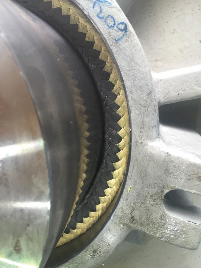
So, what makes for quality packing? First, the yarn needs to be sufficiently strong to prevent the slurry from penetrating into the fibre. It should be woven in a manner that creates a torturous leak path.
The packing needs to be low friction for low energy consumption and to reduce any damage to the rotating shaft, despite the presence of slurry. It should also be flexible enough to transfer the axial energy into radial load and maintain a positive seal for prolonged periods to reduce the amount of follower adjustments required during the life of the packing.
A. W. Chesterton Company offers quality solutions for both packing and sealing applications. Chesterton® specialists can help guide operators in the selection of a sealing arrangement to best suit their applications, without compromise or bias to one particular solution.
In conclusion, slurry pumps play a crucial role in mining operations. By examining operating conditions and requirements and choosing an appropriate sealing solution, pump uptime can be increased, water consumption reduced, and high productivity maintained.

WARRAWOONA GOLD

Australia’s Pilbara Goldfield and is owned by Calidus Resources, which estimates a sustained cost of $1,290 per ounce of gold during the mine’s years of operation.
A positive feasibility study released in September 2020 highlighted that these results could be achieved via a 2mtpa conventional Carbon in Leach (CIL) processing circuit with single stage crush and SAG mill.
The study also highlighted that underground reserve increases by 30 per cent due to planned resource extensional and infill drilling.
The potential output of this mining region could be increased, with Calidus undertaking a Definitive Feasibility Study on the nearby Blue Spec Deposit, due to be delivered mid-2022. The study is investigating how Blue Spec could leverage the existing Warrawoona infrastructure to make the most of the equipment and facilities at the mine.
over 54 months. Macmahon has also been awarded contracts with new mining clients Strandline Resources and Bellevue Gold in Western Australia.
Mining methods
Calidus contracted Macmahon for its open pit and underground mine design, which is expected to produce $220 million in revenue over 54 months.
The Klondyke deposit will use conventional open pit mining methods, including cleaning, stripping and stockpiling of near surface material, initial pioneering work in pit areas with high topographic relief to establish suitable sized working bench areas for the proposed mine fleet and RC grade control programs.
This also includes haulage of ore to the run-of-mine (ROM) pad stockpiles to be fed to the crusher and haulage of waste to nearby WRDs or in-pit backfilling.
Mining was conducted in two phases. The first phase, pioneer mining, proceeded until a 35m mining width was achieved. Areas were selectively drilled, blasted and mined, before commencing the second production phase with normal mining operations.
The mine uses a CIL process, which extracts and recovers gold from the ore. Using this method, crushed gold ore is treated with cyanide and carbon leached simultaneously, lowering operation costs and increasing gold recovery rate to almost 99 per cent.
Gold leaching begins with comminution, where ore is crushed and ground into fine particles. Water is then added to the product, creating a mud-like slurry that is then pumped into a thickener. In the thickener, gold particles sink to the bottom, and are passed to processing downstream.
The next processing phase is a CIL circuit, where cyanide is used to dissolve the ore. Then, activated carbon is fed into the process in the opposite direction of the slurry stream flow, and gold adsorbs onto the carbon. The carbon moves into an elution column, which reverses the adsorption process, stripping gold off the carbon.
Gold sludge is then removed through a pumped water spray, before the product is mixed with fluxes and heated in a furnace to produce bars that will be transported to a gold refinery for further purification.
As the ore from the mine is relatively soft, a stage three crushing plant was chosen for cost and maintenance savings. Because the transitional ore is soft, the rate that the plant processes the raw material is theoretically higher. However, to prevent overuse of the downstream comminution circuit, the design feed rate was limited to 2.4mtpa.
The transitional ore throughput rate was the determining factor in the design of the processing plant’s conveyors, leaching circuits, thickener and tailings pumps.
Employing pumps across the project
Slurry pumps
The mine will use slurry pumps to move residual byproduct from the processing plant to be stored in a tailings pond. The extreme pH levels and viscosity of tailings ponds causes wear on centrifugal and positive displacement pumps, as
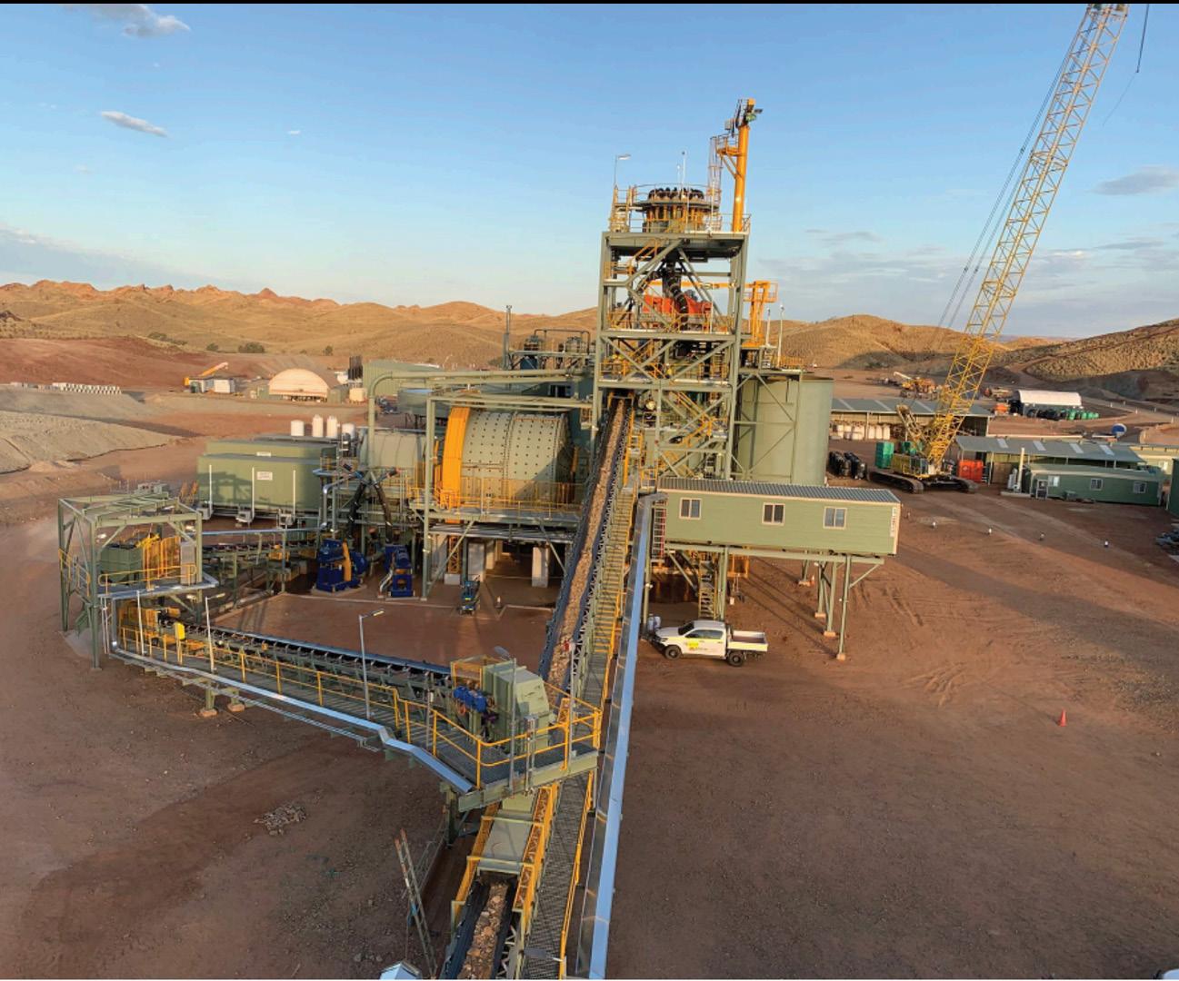
extremely acidic or alkaline tailings wear out the impellers on centrifugal pumps, causing them to lose tolerance and suction abilities.
Centrifugal pumps can be used to pump tailings up to a limit, beyond which positive displacement pumps are required (typically a piston diaphragm or hydraulic piston pump).
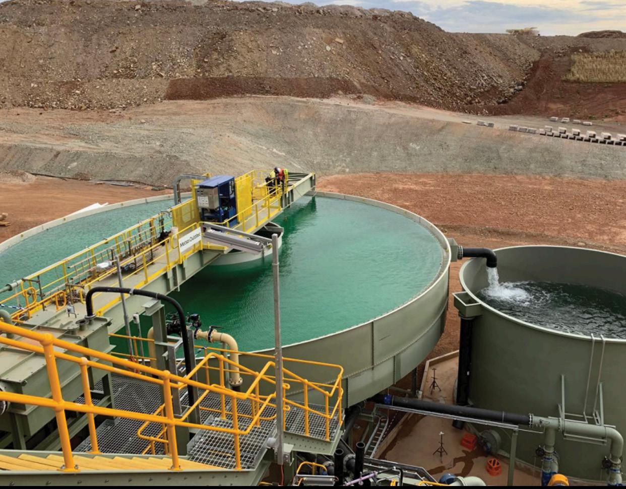
Thickener Water Commissioning.
Credit: Calidus Resources.
Thickener pumps
The mine will make use of powerful thickener pumps, which can handle the abrasive high viscosity and high density mineral concentrate in thickener underflow transfer. Thickeners increase the content of solids and the gold concentration of the slurry, separating water and processing it back upstream for recycled use. Thickeners also separate unwanted product and process it into the tailings stream.
Thickeners require valve installations for both overflow and underflow control. Butterfly valves and knife gate valves are the most common solutions for thickener overflow, while pinch and knife gate valves are most common for underflow.
Centrifugal pumps are most commonly used in mineral extraction process plants, and are designed to function in severe conditions for long periods of time. Because of the excessive wear on the inter-stage passages of these pumps,
they are single-stage equipment, with wear life of wetted components lasting up to two to three months.
When centrifugal pumps become overloaded, they can “pack up” and remove far less pulp, whereas the diaphragm pump can more easily compensate for overload. Diaphragm pumps can be regulated to accommodate any rate of flow, increasing or decreasing the rate of discharge until the density is correct.
Hose pumps can run dry with no risk of damage, and allow for quick and easy replacement of the pump. Because there are no moving parts in the product area, the product only comes into contact with the hose component.
Tailings pumps
A tailings dam has been constructed as part of the project, and tailings pumps will be used to move the mine tailings from the mining operation to the dam. Tailings present a number of challenges for pumps due to the high solid slurries, which often have very low or very high pH levels. High solid slurries can damage traditional centrifugal pumps due to wear of components, causing them to lose suction and efficiency. On the other hand, acidic and alkaline tailings cause troubles for centrifugal and positive displacement pumps, causing impellers to wear out and resulting in tolerance loss, reduced suction capabilities, and costly downtime and spare parts.
Due to this, slurry pumps are used for tailings transfer as they are designed specifically for pumping media that contains solid particles, as well as solvents, acids, alcohol or petroleum. They are more robust than other pumps in order to be able to withstand the additional wear they are subject to, ensuring a longer pump life and less maintenance.
Tailings storage facility
According to the works approval provided by the Western Australian Department of Water and Environmental Regulation, the tailings storage facility decant structures requires a mobile decant pump on the upstream side of the embankment to collect supernatant water released from the discharged tailings slurry into the facility, with incidental rainfall runoff and transferred seepage recovered from the seepage collection trench.
For underdrainage, a seepage interception trench downstream of the main embankment is needed to allow for collection and return of any near surface seepage. The trench

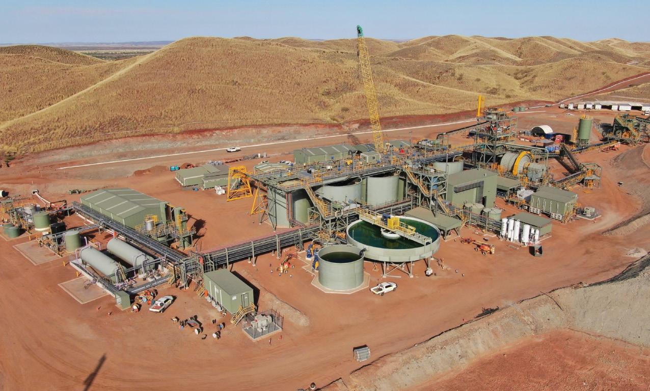
is to run parallel to the main embankment downstream toes. If seepage is intercepted by the trench, a submersible pump is to be installed in a seepage recovery sump to pump water back into the facility impoundment to be collected by the decant recovery system.
Daily inspection logs are also required for all pumps and valves in the facility.

Mill lubrication
The mill requires a hydraulic lubrication system, whereby a pump forces oil to flow into gears and bearings to lubricate the engines. These systems typically utilise lubrication pumps, as well as a range of valves including check, relief and ball valves.
Depending on the design of the system, different lubrication pumps will be more suitable. In circulation lubrication, gear pumps are generally used as they are able to generate high static pressure in the system; special piston pumps are typically used for fresh oil or economy lubrications systems; volute casing or multistage pumps are used to supply oil to large plain bearings as they have a throttling bush at the shaft passage; and for grease-lubricated plain bearings, piston pumps can be used.
Process plant commissioning
In May, the first gold pour from the Carbon in Leach (CIL) Circuit was achieved, marking the successful completion of commissioning of the full processing circuit. A total of 33kg of gold was poured.
The processing plant is also now fully operational and has achieved milling rates of 2.2Mtpa with the full ramp up to 2.4Mtpa expected to be completed in the second quarter of the year.
Calidus Managing Director, Dave Reeves, said, “Commissioning of our processing plant was highly successful and is a tribute to the skills of our team. We are increasing throughput and gold output with the aim of reaching full production rates this quarter.
“We wish to thank all Calidus personnel, who, with our key contractors GR Engineering Services Limited, Machmon Holdings Limited and Assetlink Services Limited, have allowed us to deliver the Warrawoona Gold Project, on time and on budget.
“Over the remainder of the quarter, we will focus on our operational ramp up and other site activities including our active exploration programs that have taken place during the course of development.”
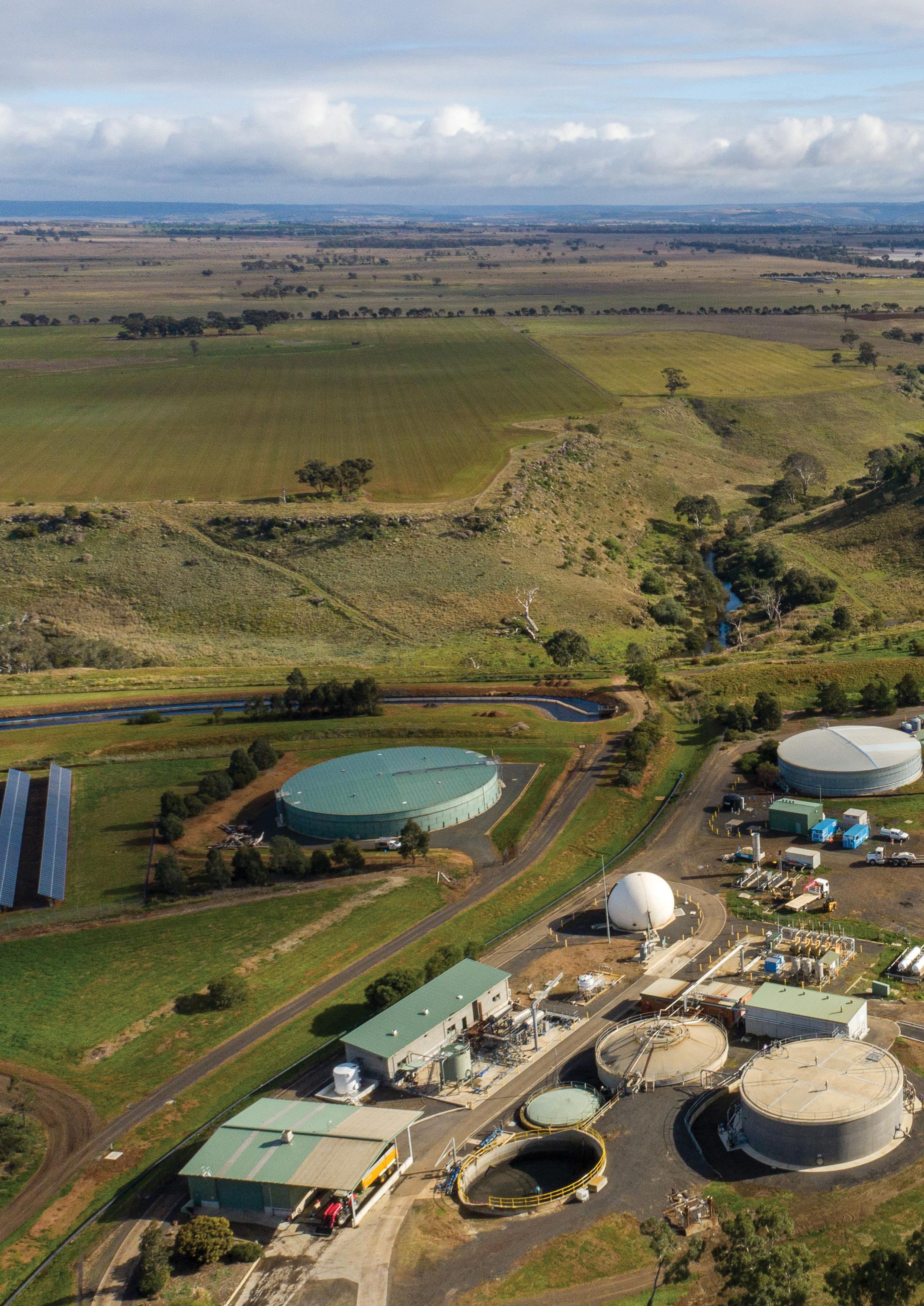
BUILDING IRRIGATION INFRASTRUCTURE
with whole-of-community benefits
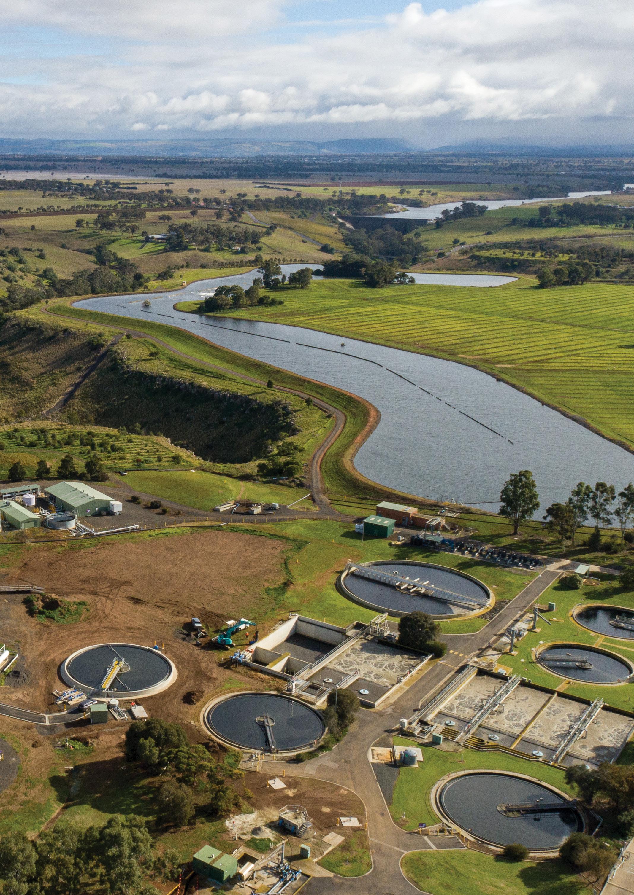
Rapid urban growth in Melbourne’s west is forecast to produce significantly more recycled water over the coming decades. This presented a challenge to Greater Western Water to find more uses for the additional recycled water that would deliver community and environmental benefits. The Western Irrigation Network (WIN) was selected as the best option and has the additional benefit of increasing water security for farmers to the west, enabling them to improve productivity and expand agriculture in the region.
The $116.3 million WIN project consists of 59 kilometres of pipelines connecting the Sunbury, Melton and Bacchus Marsh recycled water treatment plants, and four large pump stations, along with three large water storages – each over 1GL – to provide storage over winter when irrigation demand is lower.
It is a major intergenerational and long-term project for the region, aimed at addressing how Greater Western Water can best manage the sewage volumes and excess recycled water produced by the growing population.
Greater Western Water considered several solutions to the challenge, and ultimately selected WIN as it will produce the best outcome for its customers, the community, farmers, environment and local waterways, as well as for the utility itself.
As the populations in Sunbury, Bacchus Marsh and Melton grow, Greater Western Water will deliver excess recycled water suitable for irrigation (Class C) through WIN to farmers in the Parwan-Balliang District. This district to the west of Melbourne is home to a number of dryland farms, where the area has rich fertile soil but limited and unreliable rainfall. WIN will bring a reliable water supply to the region, transforming it into a climateresilient irrigation precinct, providing farmers with an opportunity for economic development and supporting Victoria’s food bowl. It will also address the challenge of sustainably managing increased amounts of wastewater from the growing population in Melbourne’s outer west.
It will initially supply 2.4 billion litres of recycled water annually from mid2023, and by 2050, up to 18 billion litres
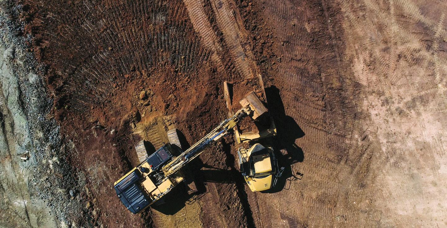
will be available each year, with volumes increasing as irrigators adapt and expand production.
Project planning and hitting major milestones
Amanda Smith, General Manager Growth and Infrastructure at Greater Western Water, said planning for the project began in 2017 and involved significant stakeholder engagement, particularly with local agribusinesses in the Parwan-Balliang agricultural district.
“With the stakeholder needs understood, an operational model for the network was established to determine the most efficient way to move recycled water to where it is needed most,” Ms Smith said.
“The model determined the optimal staging of the project to maximise the use of recycled water and flexibility to meet new demands as wastewater volumes grow in the future.
“This flexibility will allow new growers to join the network and foundation customers to expand their production systems, or to introduce new crops that require a higher volume of water.”
Construction began in late 2020
following the signing of a funding agreement between the Australian and Victorian Governments. The project recently reached a major construction milestone with the completion of a new 1.1 billion litre storage dam at Greater Western Water’s Melton Recycled Water Plant. Water is now flowing into the dam and will be delivered to farms from mid-2023, in time for the 2023/24 irrigation season.
Construction has also commenced on the first pump station which will pump recycled water from the Melton Recycled Water Plant to the foundation customer farms via a long-distance pipeline. Works to construct the pipeline are due to commence later this year, with contracts recently awarded.
The pump stations
The network will include four new high-capacity pump stations, equipped with a total of 20 pump sets and variable speed drives.
“A reference design and specifications were developed by our engineering partner, which included performance bands and control
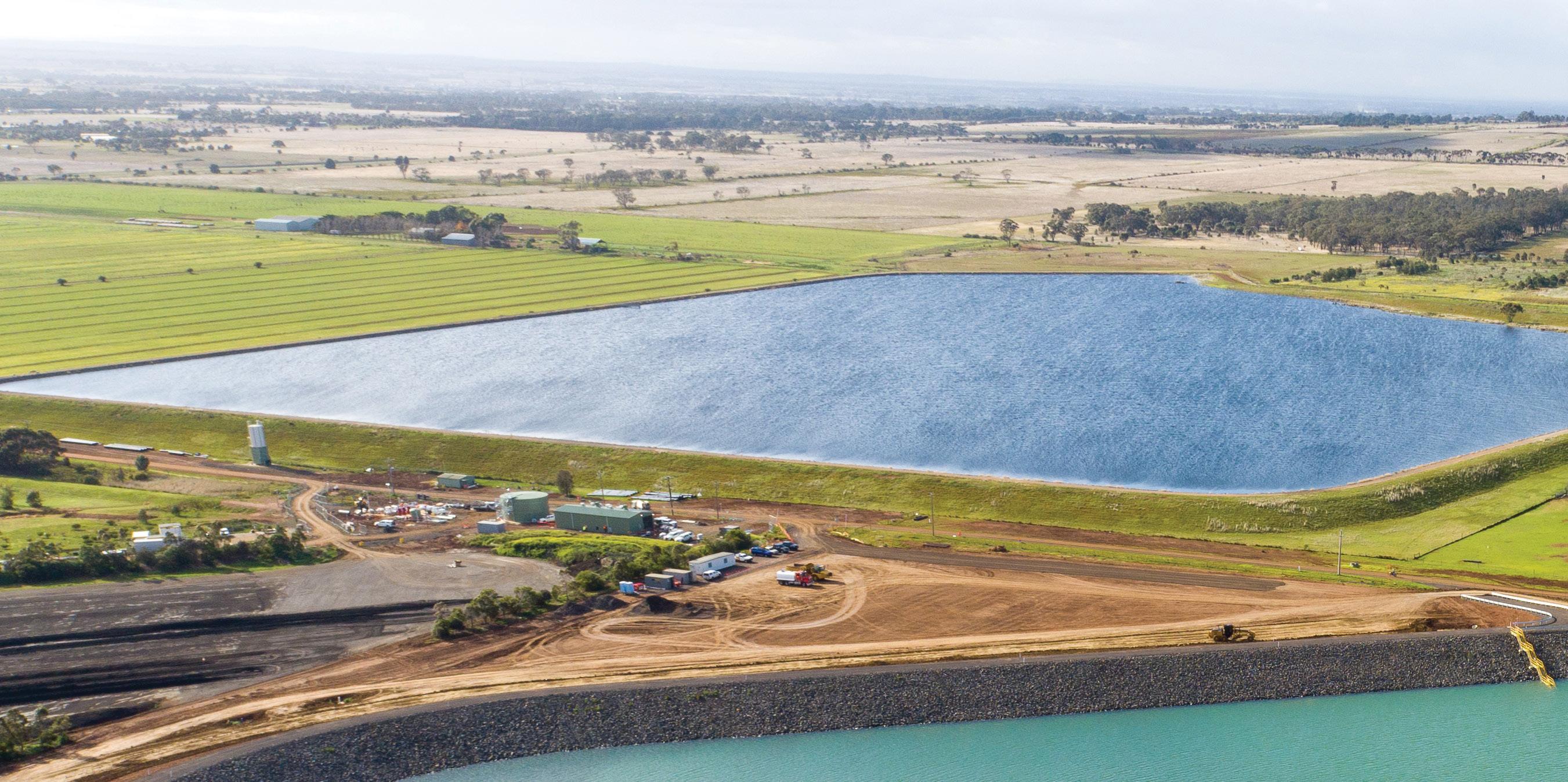
requirements for each of the pump stations,” Ms Smith said.
“This was followed by a two-phased procurement process that included an expression of interest and shortlisting process, followed by a request of tender phase for the design and construction of the pump stations.
“Greater Western Water is seeking long-lasting performance, so high reliability was a key factor. Submissions were therefore assessed for total project cost over the life of the infrastructure. This approach provided us with the best opportunity to leverage the expertise of our delivery partners and challenged them to seek innovative solutions.”
Pump specifications
Ms Smith said the selection of pumping equipment considered energy efficiency, interchangeability where possible, high reliability and local support.
“The four high-capacity transfer pump stations included in WIN will operate in series and have a wide flow range. The range will vary from approximately 250 litres per second to 800 litres per second, ensuring the network can adapt to customer demands. To manage energy consumption, high-efficiency pumps were selected to transfer recycled water to farmers and allow irrigation to occur without re-pumping.” Ms Smith said.
“The varying WIN customer demands present a complex operational challenge. We’ve managed this by including balancing storage tanks ahead of each pump station to provide a hydraulic buffer, redundancy and improved system control.
“The transfer pump station and pipelines will be equipped with smart
SCADA programming to ensure pumps are running at the best efficiency points. Pump performance is monitored by heat, vibration, pressure and flow sensors to identify premature wear conditions and energy wastage.”
Overcoming challenges
Ms Smith said delivering the project in a pandemic environment presented numerous challenges, including:
• Procurement of equipment and materials was impacted by international supply chain interruptions and border closures
• In-field investigations and foundation customer interactions were also impacted, especially with the project spanning metro and regional areas
There are also learnings the utility is taking away from the project.
“The planning approvals required for the long-distance pipelines have provided several learnings, particularly around cultural heritage and environment approvals,” Ms Smith said.
“As the project spans the Country of three Registered Aboriginal Parties, engagement with First Nations communities has presented opportunities to learn more about the Country we are working in and ways to work together for better cultural heritage outcomes.
“Thanks to this engagement, we have refined the project’s construction footprint and ran targeted ecological surveys to deliver better environmental outcomes.”
Community and environmental benefits
The WIN project is a great example of a circular economy initiative that can deliver whole-of-community benefits for the region serviced by Greater Western Water.
For farmers, it provides them with greater water security and the knowledge that there will be water available year-round to water crops, even if there is below-average rainfall. By providing access to a guaranteed, costeffective water supply, WIN will help existing agribusinesses expand, creating new jobs and contributing to local and state economies.
WIN will also address the challenge of sustainably managing the increasing volumes of wastewater caused by rapid population growth in Melbourne’s outer west. As the population in this region increases, there is a need to find a use for all the extra recycled water produced.
Excess recycled water is either stored for later use or released into waterways near Greater Western Water’s treatment plants under strict guidelines from Victoria’s Environment Protection Authority. By greatly increasing the use of recycled water for irrigation, WIN will reduce the discharge of treated wastewater into local waterways, improving waterway health and protecting the environment.
By creating a new, sustainable recycled water supply, the project also future-proofs precious drinking water supplies across communities experiencing strong population growth and warmer, drier climate conditions.
“WIN is an exciting opportunity for the region and its success will rely on the strong partnership developed with the community enduring,” Ms Smith said.
The project is jointly funded by the Federal Government, Greater Western Water and the private agribusinesses that will become WIN’s foundation customers.
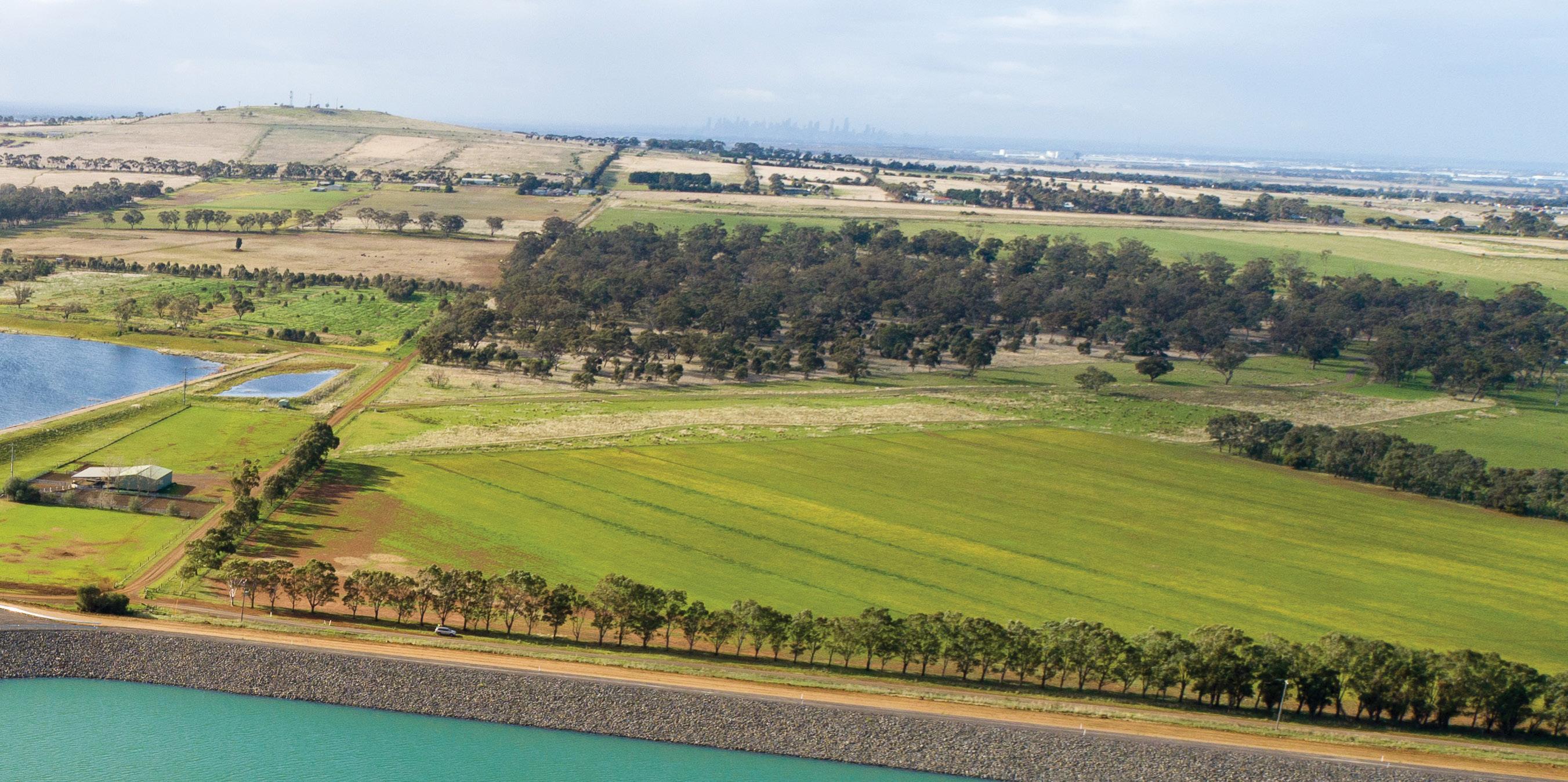
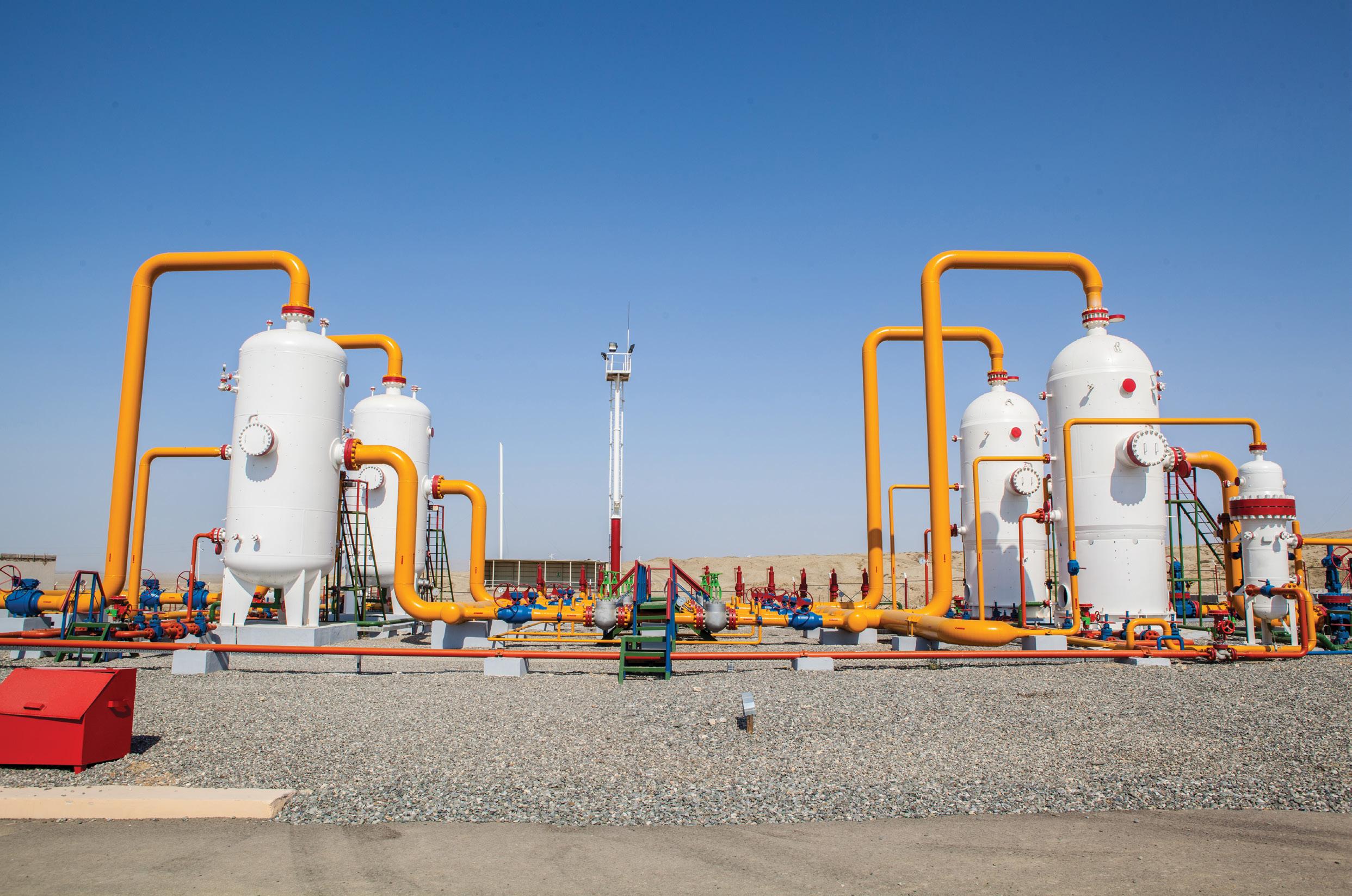
UNDERSTANDING COMPRESSOR STATIONS: the heartbeat of natural gas pipelines
By Lauren DeLorenzo, Journalist, Pump Industry magazineDemand for natural gas projects is set to increase substantially over the coming years – but that can’t happen without compressor stations driving these projects forward. No matter the size or location of the project, compressor stations are essential for the movement and optimal efficiency of natural gas pipelines.
With a variety of functions and features, compressor stations are the pulse of natural gas pipelines, making sure gas travels from the wellhead to your BBQ without interruption.
Australia’s natural gas network is currently made up of over 47,000km of transmission pipelines. When travelling over long distances, natural gas loses pressure and movement slows. This is especially common when gas is travelling to an end user living in a rural or mountainous area, and changes in terrain or elevation can lead to drops in pressure along the pipeline.
The main function of a compressor station is to propel the medium forwards by boosting pressure and keeping natural gas moving through the network.
Compressor stations are usually centrifugal compressors powered by turbines, electric motors or reciprocating compressors. Compressor stations are often powered by the gas that they are compressing, making them extremely efficient. They may also be electronically powered for environmental or security reasons. These stations are positioned at intervals along the pipeline, and are typically needed every 60-100km. Some modern compressors stations are operated remotely, with only a small crew or maintenance team on staff.
It’s clear that compressor stations are an integral part of maintaining efficient operations in natural gas pipelines. Here, we break down the wide range of components and functions that they can entail, why they are so essential
and how to optimise compressor station efficiency in the future.
What are the functions of compressor stations?
Compressor stations perform several important functions beyond boosting gas pressure.
As natural gas travels through the pipeline, it can pick up contamination, such as water molecules or small pollutants like clay or soil. Compressor stations use technology to filter through impurities and ensure that clean, uncontaminated gas is moving through the pipelines and back to the end user.
Natural gas enters a compressor station through station yard piping, and then is passed through scrubbers to strip hydrocarbons out of the gas stream, removing particles of water and filtering through the gas. Compressor
stations also use strainers or filter separators to remove liquids that may condense out of the gas as it moves through the pipeline.
By-products, such as natural gas liquids, can be collected in tanks and trucked off-site to be sold. Some of these liquids can then be used as a blend in motor gasoline or other chemical mixes.
Once the gas has been cleaned, it is directed to individual compression units, where computers regulate the flow and number of units that are needed to pressurise the gas.
Some compressor stations include odourisation equipment, which infuses the odourless natural gas with mercaptan, a substance that gives gas its pungent “rotten egg” smell. Although unpleasant to be around, this odour is an extremely important safety measure. The smell can quickly alert end users to gas leaks, without needing to wait for someone to routinely check equipment.
Types of compressor units
Most compressor units operate independently alongside each other. However, when the incoming natural gas needs a very high boost in pressure, several compressor units can be used in series to achieve the high pressure in a number of stages.
Typical operating pipeline pressure can range from 200 to 1,500psi, depending on the elevation, terrain and diameter of the pipeline. This means that the compressor unit may compress gas at different levels.
Compressor units typically operate in one of three ways. The first is where the turbine turns a centrifugal compressor, which is powered by natural gas from the pipeline itself. The second is where a high voltage electric motor makes a turbine turn a centrifugal compressor.
Centrifugal compressors increase gas pressure by adding velocity to the gas as it moves through an impeller, forcing the flow to spin faster. As the gas leaves the impeller, it travels at an accelerated rate. Kinetic energy increases the pressure of the gas by then slowing the flow through a diffuser. Centrifugal compressors have better isothermal efficiency than reciprocating compressors, but are not as flexible.
The last type of compressor unit is a reciprocating compressor, which is also fueled by natural gas from the pipeline and uses large piston engines to turn reciprocating pistons located on the side of the unit. The movement of the piston changes the pressure, and the reciprocating pistons then compress the gas.
These units can accommodate all volume capacities and pressures, making them particularly valuable in natural gas projects, where gas pressures can fluctuate. However, because these reciprocating compressors have a larger number of moving parts, they require increased lubrication of cylinders and pistons. Compressor valves, which are responsible for controlling the flow of gas through the machine, can easily get damaged or worn, and therefore these compressor units can require high levels of maintenance.
Once it has been pressurised, the natural gas is directed back into the pipeline to be delivered to end users.
Components of compressor stations
Natural gas compressor systems contain several safety systems, monitoring implementations, and backup measures to ensure safety and reliability.
Heat is generated when gas is compressed, with every 100psi increase in pressure creating a seven to eight degree increase in natural gas temperature. If the gas is sent back into the pipeline at a high temperature, it could potentially damage the infrastructure of the pipeline and associated equipment. Compressor stations need to have safety measures in place to cool the gas to a manageable temperature before the gas is sent out into the pipeline again.
Most compressor stations include an aerial cooler system to dissipate heat of the gas. The heat generated by the compressor itself is dissipated through a sealed coolant system.
All of these processes tend to generate a lot of noise, and so most compressor stations are also fitted with muffler systems, especially when located near residential areas. Muffler systems aim to suppress sound levels to around 55 decibels while operating at full capacity. Because of this, compressor stations are often housed in a building (typically including one compressor per building) to mitigate the loud noise with insulated walls. Steps to deaden the sound of operating compressor stations can include insulation of turbines, shielded exhaust systems, advanced fan technology, strong weather stripping, air inlet and air discharge mufflers.
Compressor stations also help manage the supply and demand of natural gas through pipelines with their storage functions. Sometimes, supply of natural gas through the pipeline can exceed end user demand, and the excess gas can be stored in compressor stations. On the other hand, natural gas
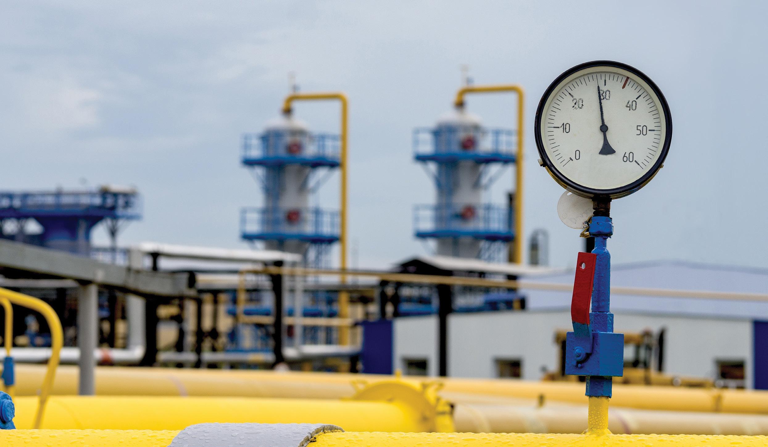
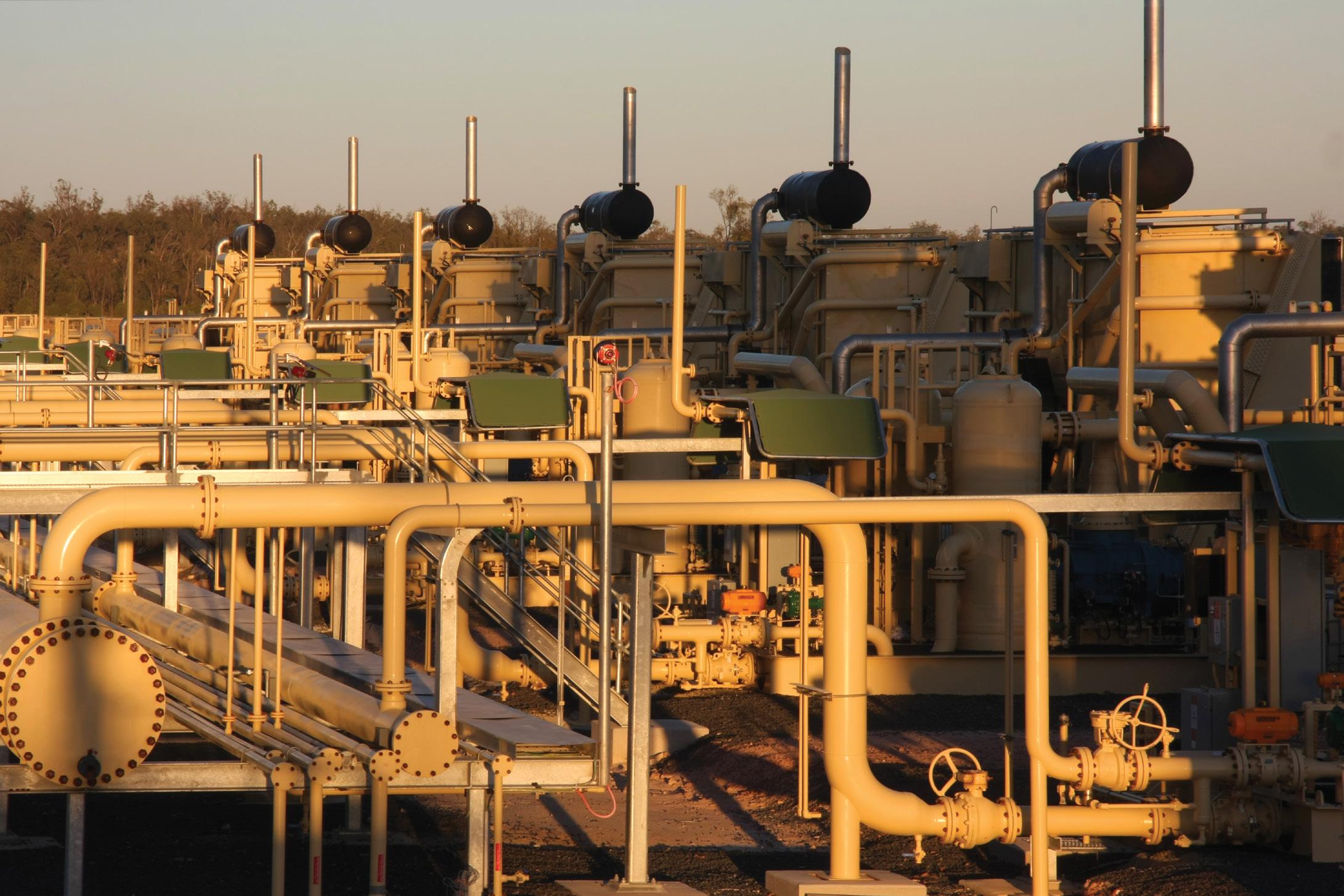
stores in compressor stations can fill gaps in supply when demand increases.
Because compressor stations play such a critical role in the supply of natural gas, they are usually fitted with backup generators to keep gas flowing. Emergency shutdown systems are usually featured to allow gas to be rerouted if necessary. Compressor stations can also include infrastructure to allow PIGs to be launched and received at the station to inspect and clean the pipeline.
PIGs can inspect and clean the pipeline without stopping the flow of natural gas, and are therefore extremely useful in compression stations. PIGs can be inserted into a funnel-shaped Y section in the pipeline – the PIG launcher – which is then closed, and the pressure of the gas in the pipeline is used to push it along the pipe until it reaches the receiving trap.
Metering systems are standard for compressor stations, allowing for monitoring of gas storage levels and the amount of gas going in and out of the compressor station. Monitoring is vital to determine the amount of compression required at each station, which will change depending on the pressure of the gas as it arrives.
Monitoring systems also help determine whether compressor stations need to burn off excess gas to dispel
vapours recovered during the removal of impurities from the gas. It’s important that these monitoring systems are accurate to ensure that stations are complying with emissions regulations. This is especially critical for compressor stations that are powered by combustion engines, which emit exhaust gases into the atmosphere and can be a potential source of methane emissions.
Because many compressor stations in Australia are located in remote areas, it is critical that these systems are designed to be operated remotely. This includes having real-time monitoring of process controls for compressor units, especially when multiple compressors are operating at the same time.
Safety and regulations
Compressor stations include emergency shutdown systems which are connected to control systems that can detect risks or abnormalities, such as leaks or unanticipated pressure drops. These systems will stop the compressor units and isolate the compressor station piping in case of an emergency.
Compressor stations are regulated in Australia by AS 2885: Pipelines – Gas and liquid petroleum series and must meet environmental standards in their area of operation.
Optimising compressor stations
In Australia, it is typically more costeffective to install a compressor station compared to installing a looping or additional parallel pipeline. There are a number of ways to optimise efficiency of compressor stations.
Placing compressor stations close together can reduce the fuel cost, but will increase maintenance requirements. Planners should also consider whether the station will deal with a relatively consistent gas supply, or whether the supply is expected to fluctuate.
A station that runs under a wide fluctuation of supply will often operate in part load, meaning a higher fuel consumption. Spreading the load across all units evenly, and running the least amount of units possible, can make a station more fuel and cost-efficient.
This can be done by running gas turbines at the same load setting or by running compressors at the same distance from their surge lines. To take optimisation of a compressor station even further, modelling the entire pipeline network can allow for further efficiency.

The biggest upcoming natural gas projects
By Lauren DeLorenzo, Journalist, Pump Industry magazine
According to analysis by GlobalData, Australia can expect 118 oil and gas projects to be up and running between 2021 and 2025. With an expected gas shortage on the horizon, there is even more pressure on these projects, and the pumps that power them, to accelerate to construction phase. Here, we take a look at some of the biggest upcoming projects in Australia, and the critical role of pumps in their operation.
Existing project expansions
Gorgon Stage Two Development
As one of the world’s largest natural gas projects, the Gorgon Project produces a daily average of 2.6 billion cubic feet of natural gas (equivalent to 300TJ) and 18,000 barrels of condensate.
The $36 billion facility comprises a liquified natural gas (LNG) plant and a domestic gas plant on Barrow Island, Western Australia. It draws from Gorgon and Jansz-lo gas fields, located between 130 and 200km off the north-west coast of Western Australia.
The project is operated by Chevron Australia (47.3 per cent stake) and is a joint venture between ExxonMobil, Shell, Osaka Gas, Tokyo Gas and JERA.
As the field has been producing gas for close to a decade, reservoir pressure is expected to decline. Additional compression will enhance field recoverability and extend long-term gas supply.
Stage two development plans include installing three additional infill wells, and connecting them back to the existing Gorgon M1 Manifold. Four wells will be tied back to a new Gorgon M4 Manifold,
and four will be tied to a new Jansz Drill Centre 3 combined Manifold.
This stage also involves the installation of new infield control umbilicals and interconnecting flying leads at Gorgon M4 and the Jansz Drill Centre 3.
Chevron’s environment plan for the commissioning, start-up and operation of the wells was approved in April 2022, with start-up activities expected to begin in the second half of the year.
East Coast Grid Expansion
APA Group is expanding its east coast gas grid to meet winter gas supply shortfalls from 2023 onwards.
The $270 million expansion aims to increase winter peak capacity of the east coast grid by 25 per cent, with works taking place in two stages.
Stage one of the project began in the first half of 2022, and involves the construction of a compressor station on both the South West Queensland Pipeline (SWQP) and the Moomba Wilton Pipeline (MWP) for a 12 per cent increase in gas transportation capacity.
Stage two will add a further 13 per cent of capacity with an additional site on the SWQP and MWP.
A potential third stage, which is currently undergoing design works, would add another three compressor stations on the MWP for a further 25 per cent transportation capacity.
Each compressor station is expected to take approximately nine months to build. Approval has been granted for the first two stages in Queensland and New South Wales, and management plans for Stage one are now underway.
Ongoing projects
Surat Gas Project
The Surat Gas Project is an ongoing coal seam gas development operated by Arrow Energy, that aims to commercialise the company’s gas reserves in the Surat Basin in Southern Queensland.
With a 27-year lifecycle, the project will include 2,500 new wells and create an estimated 1,000 jobs, presenting vast opportunities for pump manufacturers.
The first phase of development began construction in 2020, with the installation of more than 600 wells expanding north and south from the project’s current operational areas. The wells will range between 150m and

750m in depth, with a production life between 15 and 20 years.
The gas from the production wells will be transported to the facility through low-pressure gas gathering pipelines, while the gas between the compression and processing facilities will be transported by medium pressure gas lines. A high pressure pipeline will transport gas from processing facilities to the off-take gas pipeline.
This phase also included construction of inlet processing facilities at field compression stations, in addition to upgrades and connection to water treatment facilities.
New infrastructure will also be built at Arrow’s Tipton and Daandine water treatment plants to send water to the Kenya Water Treatment Facility. Two brine storage ponds will be built to support coal seam water treatment for a Beneficial Use Network, which is expected to be in place by 2023.
Future development phases include construction of two new field compression stations – one located at Lynwood, and another located at Girrahween. The wells and gathering
pipelines will be constructed near the compression stations, and in areas south of Wandoan and Cecil Plains.
There are also plans to install two additional inlet processing facilities at Shell-operated Jammet and McNulty field compression stations.
Barossa Offshore Project
This planned offshore gas field is being developed by Santos and its joint venture partners, ConocoPhillips Australia Exploration and SK E&S Australia.
The Barossa project will involve a floating, production, storage and offloading facility that will provide a new source of natural gas to the existing LNG facility in the Northern Territory.
Development of the Barossa project will involve the floating production storage and offloading facility, subsea production system, supporting infield subsea infrastructure and a gas export pipeline.
The floating facility will separate the natural gas and condensate with the dry gas through the export pipeline, before being processed onshore.
Allseas Marine Contractors Australia will construct the proposed export pipeline, which will be approximately 260km long.
Development drilling is planned to begin mid-2022, with pipeline installation set to begin before the end of the year.
Amadeus to Moomba Gas Pipeline
The Amadeus to Moomba Gas Pipeline is a planned pipeline led by a joint venture between Central Petroleum, Macquarie Group and Australian Gas Infrastructure Group.
The $1.2 billion pipeline will run between the Amadeus Basin in the Northern Territory to Moomba, South Australia, and is expected to deliver 140TJ per day when operational.
It is planned to be 950km long and up to 16 inches in diameter, and will result in lower transport costs by halving the current distance that the natural gas has to travel.
Construction was set to begin in 2022, with operations planned for 2024. Upcoming developments
Crux project (Browse Basin)
Shell Australia and its joint venture partner, Seven Group Holdings Energy, have developed plans for a $2.5 billion Crux natural gas field off the coast of Western Australia.

The project consists of a remotelyoperated platform from the Prelude floating liquified natural gas (LNG) facility. Initially, five wells will be drilled, and an export pipeline of approximately 160km will be built to connect the platform to the Prelude facility.
The project is expected to supply up to 550 million standard cubic feet of gas per day to Prelude once it begins operations.
Construction of the Crux project is expected to begin in late 2022, with production beginning in 2027.
Scarborough gas project and Pluto Train 2
Woodside and BHP are planning an expansion of its domestic gas infrastructure to increase capacity, in addition to an offshore Scarborough gas resource.
In its initial phase, the Scarborough development will include the drilling of eight wells which are tied back to a semisubmersible floating production unit near the Scarborough field.
Woodside and BHP plan to expand the Pluto facility by constructing a second LNG train. The increased capacity will allow the facility to process third-party gas resources, including from the Scarborough project.
The second LNG train will support the facility and produce an expected eight
million tonnes per annum of LNG, with a domestic gas commitment of around 180TJ per day for Western Australia.
Bechtel has been selected as its engineering, procurement and construction contractor.
Woodside announced a final investment decision for the Pluto Train 2 Project in November 2021, and construction is scheduled for 2022.
The gas processed through Pluto Train 2 will be one of the lowest carbon intensity sources of LNG delivered to customers in north Asia, with first LNG cargo targeted for 2026.
The project is expected to create 3,200 jobs during construction, and support 600 ongoing roles.
The Golden Beach Project
Offshore from Gippsland, the Golden Beach Project is set to produce gas for the domestic market for two years before transforming into an underground gas storage facility.
GB Energy received a Federal Government loan for the project in March 2022, with the 12.5PJ of storage to alleviate gas shortages in the coming years and help cap prices.
The project involves the construction of pipelines which will connect natural gas from the Gippsland basin to existing onshore infrastructure.
It will include two subsea horizontal wells approximately 3.8km offshore, as well as a compressor station, three pipelines and associated pipeline infrastructure.
Top eight considerations when selecting a flow meter
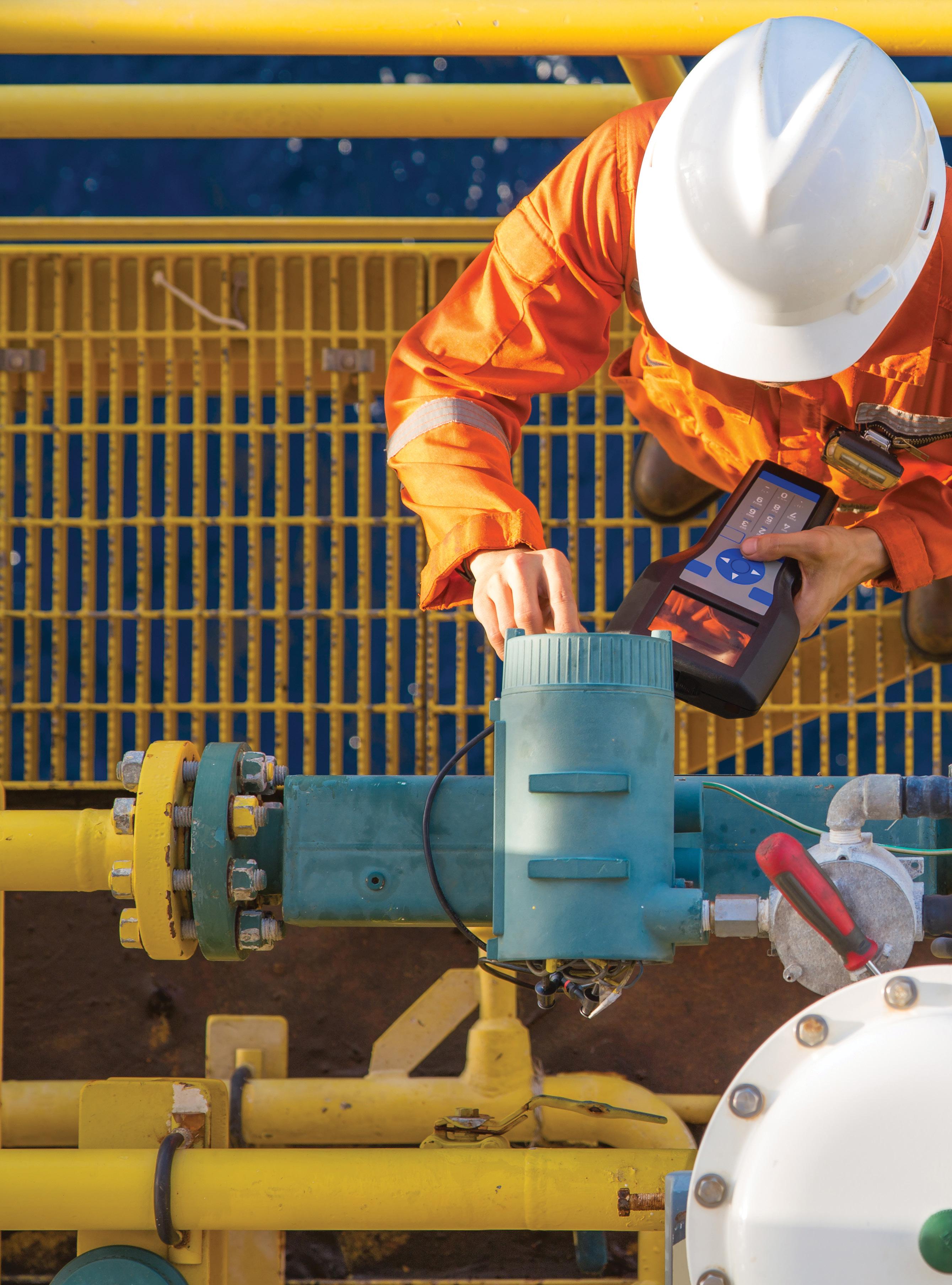
Flow is one of the most important measurements needed when controlling or monitoring what the fluid in an application is doing and that the fluid is in the right place at the right time. They provide early indication for problems that could have a major influence on the application and give end users the information they need to make informed decisions. There are a number of considerations to take into account when selecting a flow meter. Here, we look at the top eight considerations to help you select the best flow meter technology for your application.
There are four major reasons flow measurements are taken:
1. Safety – if the flow rate is not controlled, temperature and pressure can reach dangerous levels
2. Product integrity – flow plays a role in ensuring the right amount of blended materials are constantly present
3. Efficiency – the efficiency of a process can be determined by measuring the amount of each input that has gone into a product compared to the amount produced
4. Process variable control – the flow rate is measured and controlled during energy transfer applications
Therefore, accurate flow measurement is important as incorrect measurement can have serious and potentially damaging consequences, and can be the difference between a company making a profit or running at a loss.
Knowing what factors to take into consideration when selecting a flow meter will ensure you’re getting the best one for your application.
1. Process media
The characteristics of the process media is one of the most important considerations as different flow meters are designed to operate at their best in different fluids and under different operating conditions. Characteristics such as conductivity, temperature, pressure and viscosity can affect certain types of flow meters, as well as how clean or dirty the water is. This makes it important to be aware of the limitations of each type of flow meter.
Flow meters with wetted moving parts, such as positive displacement or turbine meters, are unsuitable for dirty fluid applications as they will be more susceptible to mechanical wear, plugging or erosion due to the presence of solid particles. Therefore, they are best suited for clean fluid applications.
For example, propeller meters are commonly used in drinking water systems, especially for measuring well water withdrawal. Propeller meters are a type of velocity meter that can measure fluids containing a certain amount of sand, dirt, iron, and other contaminants. However, for dirty fluid applications where the fluid contains solid particles like stringy materials and wipes, such as raw wastewater,
they are not recommended as the fluid would foul or damage the meter.
On the other hand, non-contact meters such as electromagnetic, ultrasonic or Coriolis meters are more appropriate for dirty fluid applications. While they still have limitations, they handle the particles better.
For example, electromagnetic meters are very accurate when measuring conductive materials like water and wastewater, and have no moving parts to corrode or break. There are different styles of these meters available to suit specific fluid measurements, including drinking water, wastewater and sludges.
Knowing the state the fluid being measured is in – gas or liquid – is also important. Gases can be compressed easily, so a liquid meter would be unsuitable.
Furthermore, fluid compatibility with the flow meters wetted parts, such as the body, seals and gears/ rotor/paddle, need to be considered. Thermoplastics are more compatible with acids and bases which are corrosive for metals, whereas metals are more compatible with organic compounds.
2. Viscosity and flow profile
The viscosity of the fluid also needs to be considered as when flow measurement is being undertaken, it determines how well mixed the fluid is and therefore how repeatable the reading will be.
For very viscous fluids, a positive displacement meter – such as an oval gear flow meter – is more suitable than a turbine meter, due to the laminar flow characteristic of these types of fluids. On the other hand, turbine meters can be used for fluids with a turbulent flow, usually less viscous or thin fluids, such as solvent or water. This is because it is a velocity meter, and directly measures the speed of the fluid by measuring the angular velocity of the rotor which is directly proportional to the fluid velocity.
In applications where there is a high viscosity fluid moving at low flow rates, like honey or thick oils, a volumetric flow meter is most suitable.
Viscosity is also linked to temperature – as the temperature increases, the viscosity decreases. Therefore, the operating temperature of the application needs to be
considered to understand how the fluid viscosity will behave.
3. Flow rate information
Flow rate information – the volume or mass of a fluid flowing per unit time – is needed to determine the right size flow meter for the application and will function as designed.
An undersized meter (where the flow exceeds or comes close to exceeding the meter’s capacity) will result in damage or failure of internal components, or in the worst case, will lead to complete failure. On the other hand, an oversized meter (where the flow is below or close to the minimum range of the meter) will lead to poor accuracy or inability for it to read/ measure the flow.
As a general rule, a flow meter should be sized to get between 20-80 per cent of the maximum flow rate, corresponding with the minimum and maximum flow rates. This will allow for the flow meter to perform at its optimum, and maximise its durability and longevity. It will also allow it to cope with any peak flows that may damage the meter and any lower than average flows if there is an obstruction in the line or blockage that may not register if the meter is at its limit.
4. Accuracy
Some applications may specify and require a certain level of accuracy for the selected flow meter, as an inaccurate reading could result in financial loss or a quality issue. For example, flow meters in applications to control chemical feed may require greater accuracy than those used for the general tracking of water treated. Similarly, flow meters used for bill tracking purposes need to be extremely accurate.
Flow meter accuracy is expressed as the percentage of actual reading (the error will always be the same percentage of the actual flow), percentage of calibrated span (its absolute error will rise as the measured flow rate drops) and percentage of full-scale units (the error is consistent over the full range of the flow rate for the meter). It is generally stated at minimum, normal and maximum flow rates.
Repeatability also needs to be considered with accuracy. This measures the ability of a flow meter to produce the same reading in the same conditions, regardless of the accuracy

of the meter. Repeatability is crucial as it is not possible to have high accuracy without high repeatability.
5. Temperature and pressure
The temperature and pressure conditions of an application also need to be considered when selecting a flow meter. Like flow rate, temperature and pressure parameters determine the meter’s material capability to withstand the effect of thermal energy and the forces exerted by the flowing fluid.
When considering temperature, viscosity and density need to be taken into account as these may fluctuate when there is a physical or temperature change in the fluid. Operating temperature also needs to be considered as the wetted components, such as the seals, have temperature limits and some materials will not be able to withstand extreme temperatures or extended periods of time at higher temperatures. Furthermore, the temperature will determine if an electronic instrument can be mounted on the meter or if it will need to be remote mounted as these too have temperature limitations.
Pressure needs to be considered as the operating pressure of the application must not exceed the maximum allowable of the flow meter as
it has the potential to create a hazard, as well as cause the meter to deform and likely increase inaccuracy over time. Pressure drop should also be considered, especially in applications with high viscosity fluids. When a flow meter’s pressure rating is calculated, safety is taken into consideration, allowing for small pressure spikes to occur without causing the meter to fail.
Both temperature and pressure need to be considered together as high temperatures will affect the pressure capacity of the meter, causing metals to become more ductile and likely to stretch, while maximum pressure ratings allow for the maximum temperature rating of a meter.
6. Location and installation
In order to achieve optimal performance and the desired accuracy, proper location and installation of the flow meter are crucial as even the best meter will record inaccurate readings if installed improperly. Incorrect installation usually occurs when a flow meter is forced into an existing plant or network or to make it fit in a tight site.
The piping size, material, configuration and direction all play a part in the selection of a flow meter. Piping configuration is crucial as it must be constructed in a way that the flow meter
is always full of fluid in order to provide an accurate reading. Pipe direction is also important to determine if the flow meter will be installed horizontally or vertically. Where a meter is mounted vertically, the flow should be from bottom to top so that the meter is always full of liquid and to prevent air entrapment. These issues are most commonly seen where a system has been over-designed to accommodate future growth.
Most flow meters require a specific amount of straight run pipe to prevent flow disturbances. For example, velocity meters require a straight run pipe in the upstream and downstream to get a stable flow profile. This is important to consider as an irregular velocity profile caused by pipe bends, valves, tees, and reducers will impact the accuracy and repeatability of the meter – up to 50 per cent in some meters.
In a new system, straight runs can usually be designed into the system as appropriate. However, in existing installations or constrained sites, sufficient straight runs may be difficult to find. In these situations, flow conditioners may help reduce inaccuracies by reducing swirl and disturbances, and some meters can
measure more accurately than others in these conditions.
Another consideration is the orientation of the flow meter, which should be strictly followed according to the manufacturer’s instructions.
7. Output/indication
Whether flow measurement data is needed locally or remotely and how the meter will translate the flow rate into a usable data form need to be taken into consideration in the selection process. These are determined by what the data will be used for i.e. billing, regulatory reporting or monitoring, or process control.
Remote indication can be transmitted via analog, digital or shared through protocols such as HART, FOUNDATION Fieldbus or Modbus. In some applications like large industrial facilities, readings are usually supplied to an industrial automation and control system for use in process control and optimisation strategies.
8. Necessary approvals
Before selecting a flow meter, end users need to ensure that it meets any necessary approvals for the application, such as approvals for use in hazardous areas.
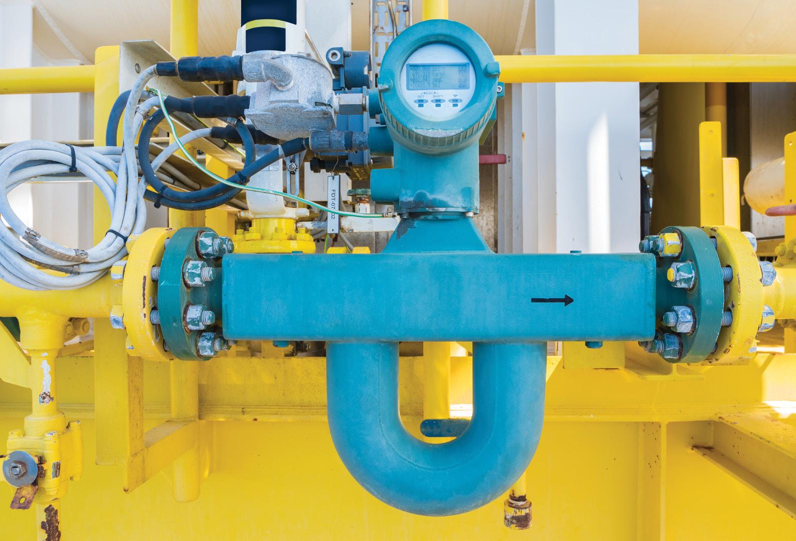
Meeting flow objectives
Understanding the key considerations when selecting a flow meter and why they are important are crucial to achieving success with flow objectives for an application. In particular, in applications where the wrong decision could have greater consequences for operational and business performance, care should be taken during the selection process and a knowledgeable instrumentation supplier should be engaged in the early stages of a project.
SANDPIPER EVOLUTION and SIGNATURE series
Engineered to deliver industry leading durability and performance, for even the most severe and demanding mining environments.
Durable and portable pumps suitable for: - Dewatering - Fuels and lubricants
- Refining, smelting and milling process
- Water treatment
We know the importance of choosing the right equipment to match your process. With our extensive range of pumps, first class customer service and ongoing comprehensive support, Kelair Pumps are second to none when it comes to your pumping requirements.
Knowing
what factors to take into consideration when selecting a flow meter will ensure you’re getting the best one for your application.
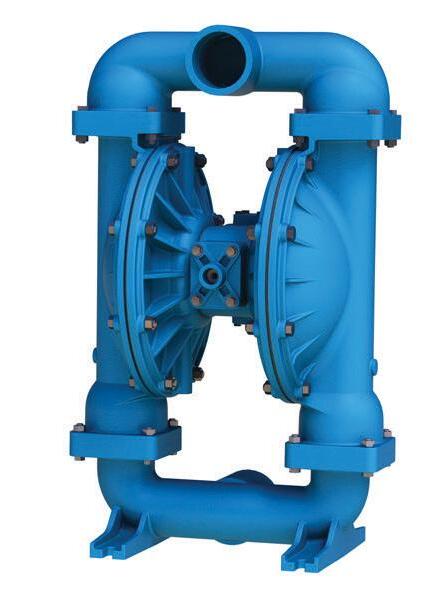
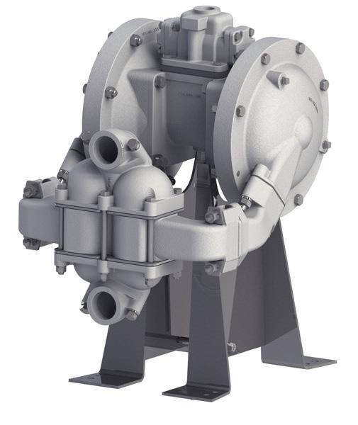

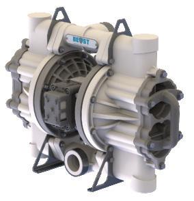


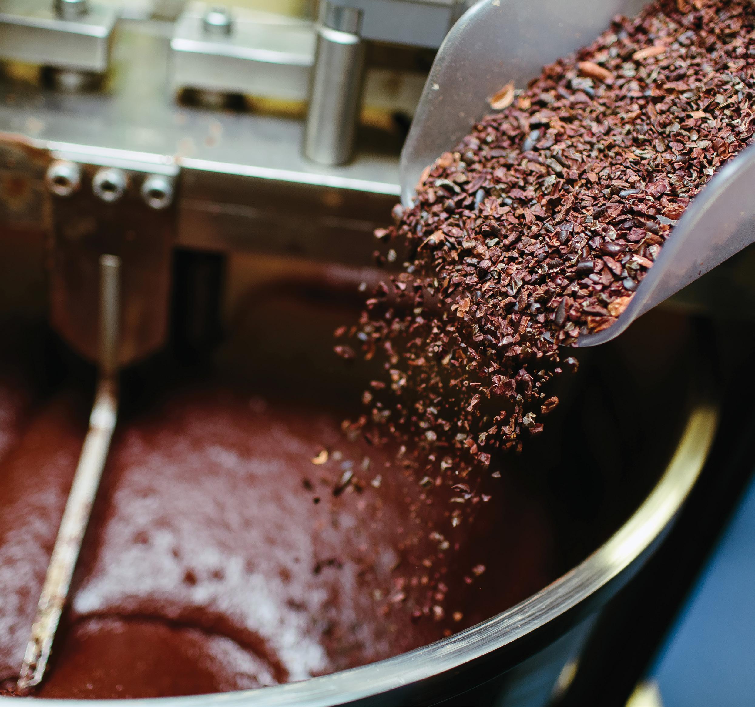
The bittersweet balance of chocolate pumps
By Lauren DeLorenzo, Journalist, Pump Industry magazineThere’s no way to sugarcoat it – finding the right pump for chocolate manufacturing is a tricky balance. Chocolate pumps need to delicately handle high viscosity mediums, maintain a consistent temperature and uphold hygiene standards. Luckily, you don’t need a golden ticket to uncover the secrets of how, where and why pumps are used in the chocolate manufacturing process.
Through milling, blending, refining, smoothing, tempering, depositing, enrobing and packaging, pumps play a critical role in bringing chocolate to the masses.
The global chocolate industry is projected to grow at an annual rate of 4.5 per cent between 2022 and 2027, with increasing demand for dark chocolates, as well as sugarfree, vegan and gluten free products, fuelling growth.
To accommodate this projected growth, the efficiency and quality of chocolate pumps will become increasingly important. But as one of the most difficult food substances to pump, chocolate poses a significant challenge to pump suppliers and chocolate manufacturers alike.
Here, we look at how pumps are used in chocolate production, common chocolate pump pitfalls and the essential qualities that pumps need to create this mood-boosting treat.
The chocolate-making process
While chocolate manufacturing processes can differ depending on the type of cocoa beans used, most use comparable machines and follow a similar procedure.
1. Winnowing
First, cocoa beans, which have been fermented and dried, will be refined by removing the outer shell (a process called winnowing) so that the nib is left over. In ancient times, this was done by throwing the grain into the air and letting the wind blow away the outer shell.
Modern manufacturers use a winnowing machine to crack the shells and break up the cocoa bean into smaller pieces (cocoa nibs). The machine vibrates, separating the nibs from the shells and removing any other impurities so that the nibs can be sorted by size and processed.
2. Refining
Nibs are then put into a refining machine, which produces heat and grinds the nibs into even smaller pieces at very high speeds. The high amount of fat in the cocoa melts down, and it is processed into a high viscosity substance called cocoa mass.
Depending on the type of chocolate, different ingredients can be added at this stage. For milk chocolate, the cocoa is mixed with cocoa butter, sugar, cocoa liquor, powdered milk and other flavouring ingredients. Dark and white chocolate have different ingredients, and flavours for specialised chocolates are added in at this stage.
3. Conching
Conching is the stage of bulk chocolate production where finishing touches are added to the texture and flavour through various mixing and grinding processes.
First, the moisture level of the cocoa is reduced, and volatile acids, like acetic acid, short-chain fatty acids and aldehydes are removed. This is done by heating, mixing and aerating the cocoa.
Then the cocoa is reshaped and run through machines to flatten and aerate the particles. This is where the particle size of the added ingredients (milk powder and sugar) is refined to make them even more uniform and to coat them more evenly with cocoa butter.
This gives chocolate its viscosity, flow and textural properties, and determines how smoothly the chocolate will melt in the mouth.
The technology used in this stage is extremely important, as consistent temperatures need to be maintained depending on the type of chocolate being made.
Some dark chocolates can be conched up to 90°C. However, milk chocolates usually need to be kept at a temperature of around 50°C to prevent caramelisation of the product, which can cause unpleasant lumps in the chocolate and clog the pumps.
Finally, tempering makes chocolate smooth and glossy, and aligns polymorphic crystals in the vat so that they all harden at the same temperature. This stage involves mixing, cooling and shaping the chocolate under precise conditions.
The challenges of chocolate pumps
Pumps are used in almost every stage of chocolate production, and as the product changes shape, size and texture, its pumping requirements change too.
This makes it a particularly challenging food to transfer, with delicate temperature, hygiene, and shear-sensitive requirements. Here are some of the most significant considerations for pumping chocolate.
Maintaining temperature
Not only do different types of chocolate need to be kept at different temperatures, but this temperature must be maintained to keep the cocoa moving through the pumps and to ensure that it doesn’t burn and affect the taste.
High temperatures can cause chocolate to congeal or caramelise, which causes lumps. As more and more
chocolate congeals, friction increases in the pump, leading to even more heat and an increased chance of blockages and damage.
Constant monitoring of the chocolate pump temperature can help mitigate this, and pumps need to be resistant to overheating.
Handling abrasive ingredients
On the other hand, as chocolate cools, it can solidify in the pump during a shutdown period. If the pump is restarted while hardened chocolate is coating the equipment, this can cause major damage.
Instead, it is critical that the chocolate is warmed and melted before the pump is restarted. This needs to be done delicately, as direct heat can burn the chocolate and ruin the taste.
One solution is to choose a pump with a single or double cover heating jacket feature, which allows for hot water or steam to run through the pump. Here, the heated water or steam runs through cavities within the pump that do not come into direct contact with the chocolate. This can be placed around the face or body of the pump.
Because of its higher thermal conductivity, iron pumps melt chocolate more quickly than stainless steel pumps.
Viscosity requirements
The viscosity of chocolate can fluctuate drastically, presenting unique challenges for pump manufacturers. At room temperature, chocolate can reach as high as 50,000 centipoise. Most manufacturers pump chocolate above 50°C, which brings the viscosity back to around 25,000 centipoise.
As a high viscosity medium, slower pump speeds are required to allow the chocolate to pass through the suction of the pump. Pumps need to create sufficient vacuum to bring liquid chocolate into the suction side of the pump and to force it out of the pump against system pressure.
Chocolate requires pumps with low discharge pressure in order to handle cocoa butter, sugar and other solid, abrasive ingredients. Keeping a pump below 300rpm is a general guideline for chocolate pumping requirements.
Hygiene requirements
Chocolate pumps need to adhere to hygiene requirements, as this is a product for human consumption. This means that pumps will need to comply with industry standards, and be made from appropriate materials.
Pumps need to be easy to clean to avoid cross contamination between different kinds of chocolates. Pumps

that are fitted with clean in place (CIP) ports can ensure that equipment is easy to dismantle and clean.
Hygienic pumps should be used when incorporating dairy products into chocolate (like when creating milk chocolate), as there is a higher contamination hazard.
Shear sensitivity
Chocolate is extremely shear sensitive – meaning that if it is pumped too quickly, the cocoa butter and other ingredients can begin to separate, leading to burned chocolate and increased chance of a blockage.
Pumps which operate at or below 101psi are recommended for chocolate production, as higher pressures can make ingredients start to separate.
Which pumps work best?
Due to chocolate’s shear sensitivity and high viscosity, centrifugal pumps are generally inefficient in the manufacturing process, as they run at high speeds and have trouble handling high viscosity.
Positive displacement pumps, however, increase in flow rate and efficiency with higher viscosity. These pumps have chambers that expand to draw liquid in, and then contract to force liquid out. Positive displacement pumps
are also a good choice as they operate at low speeds, typically less than 300rpm. It is less likely that fresh liquid will reach the area between the idler bushing and pin when pumps operate at higher speeds.
Because the flow of positive displacement pumps is directly proportional to speed, variable speed drives are able to provide a simple manual or automatic control of speed.
This is particularly useful in chocolate manufacturing, where controlling speed to match the load can help optimise efficiency and reduce the chance of ruining the chocolate through high speeds.
Positive displacement pumps with check valves and acceleration forces, such as diaphragm pumps, generally create shear, making them unsuitable for chocolate. The preferred choices for chocolate manufacturing are gear pumps, rotary lobe or circumferential piston pumps.
Gear pumps are the most costeffective option, and are easier to maintain due to their single shaft seal. However, lobe or circumferential piston pumps, which have two shaft seals, can handle chocolates that contain larger solid ingredients such as raisins, small candies or nuts.
Another consideration is minimising the shear created through discharge pressure as the chocolate passes through pump clearances. It is generally recommended to keep the discharge pressure less than 100psi. One solution is to avoid piping system restrictions which could create unnecessary backpressure.
Which materials are best?
There are a wide range of material options for chocolate pumps, with cast iron and stainless steel being the most common. Handling high viscosity chocolate means that pump components should be constructed of strong materials, such as steel rotors.
Cast iron is the most common external material for pumps in chocolate manufacturing, because it is simple to remove any metal particles contaminating the chocolate with magnetic separators. Cast iron gear pumps are the best choice for chocolates with low potential for bacterial growth.
Corrosion of these materials is not usually an issue, because chocolate pumps are not cleaned with harmful chemicals. Chocolate is not a good promoter of bacteria or fungi growth, and so equipment can be cleaned sparingly.
Pump seals for chocolate manufacturing
Chocolate can leak and harden, and so it is even more important that pumps are well-sealed to prevent leaks. Chocolate can often leak from the pump shaft. The most common and simple shaft seal solution is a packed gland with food-grade braided packing in the stuffing box.
The packing should be loose enough to allow some chocolate to leak out (up to a rate of one drop per minute), so it can cool and lubricate the packing, creating a puddle around the base of the pump (or in a collection tray).
Packing inevitably leads to some product loss, and while generally reliable, there is also the risk that operators may tighten packing glands too much to minimise leakage, which can result in scored shafts, burned chocolate and pumps locking up.
Additionally, packing may not always meet the hygiene requirements needed, and an alternative solution is using dynamic O-ring seals on the shaft. These seals are extremely tolerant, can handle high viscosity material and are low cost. A food grease barrier can be used to keep chocolate in the pump and out of the bracket, where there is the risk of it disrupting a pump. Unlike packing, they do not require re-tensioning, and can handle very high pressures.
Mechanical seals can also be used, but have a higher risk of needing replacement. This is because the chocolate at the seal face can damage the seal if it is not completely melted before start up.
Often, mechanical seals are located behind the pump rotor with a lip seal at the stuffing box. Lip seals have a maximum working pressure of four bar, and are only recommended for relatively
non-abrasive chocolates. Chocolate can crystallise on the seals and cause further damage.
More general guidelines
General guidelines for pumping chocolate include adjusting clearances and not exceeding a maximum rotor rim speed of 250.
Internal pressure relief valves should be avoided, as they are prime areas for chocolate to build up and clog the pump. Instead, external valves and other over-pressure protection measures can be used.
Fitting pumps with drilled idlers (drilling staggered holes through idler gear and bushing) can help prevent overheating and buildup of chocolate in the pumps. This allows chocolate to reach the area between the pin and idler more easily. Specialised pumps can apply cocoa butter to the idler pin for external lubrication and better flow.

WHAT TO UPGRADE IN PROCESS PUMP POWER FRAMES (PART 2)
By Heinz P. Bloch, PE, Process Machinery Consulting
In part two in this series on upgrading process pump power frames, Heinz P. Bloch provides more pointers on how to obtain improved power ends.

DN-number defines oil level preferences in bearing housings
Perhaps half of the world’s oil-lubricated industrial pump bearing housings are furnished with inexpensive oil rings, also called ‘slinger rings’, that lift the lubricant from an oil sump (Figures 1 and 2). In some applications, oil rings or small discs that just barely contact the oil at its level surface are helpful for maintaining the oil volume more uniformly mixed, ie. to prevent temperature stratification. Stratification is a term that describes hot oil floating upward and staying near the top of the oil sump. Conversely, the cooler oil has greater density and tends to sink down to the bottom of a bearing housing.
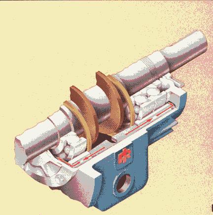
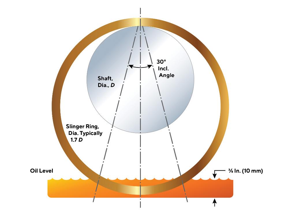
Typically, the loose oil rings shown in Figure 1 and 2 are immersed about 3/8th inch (~10-11mm) for the purpose of spraying oil into the bearings¹²³. Oil rings are not required in pumps with low-to-moderate shaft peripheral velocities. In these typical “without oil ring” designs, the oil level must reach to the center of the lowermost bearing element – usually a bearing ball. Higher shaft velocities are defined next.
Bearing and shaft velocity constraints
Bearing peripheral velocities are more conveniently expressed as DN-values, the product of multiplying inches of shaft diameter times by shaft rpm. For example, a 70mm (~2.75 inch) bearing operating with a shaft turning at 1,800 rpm would have a DN-value of 4,960; values below 6,000 are somewhat arbitrarily considered low-to-moderate DN numbers. In designs with DN <6,000 (conservative) and possibly reaching (but not exceeding) a DN as high as 8,000, both housing geometry and constant level lubricator height settings are generally selected to allow lubricating oil to reach the centre of the lowermost bearing ball or rolling element. Keep the numbers 6,000 to 8,000 in mind; they represent an interesting DN parameter¹²³.
Satisfactory oil ring functioning is obtained in the range of from 2,000-2,500ft/minute shaft surface velocity, which can be expressed in terms of diameter and rpm. Some bearing manufacturers (and also machine designers) recalculate to show the acceptable range of surface velocities that comply in the metric system. Bearing producers often use a dN expression, with ‘d’ generally designating a mean, or average, diameter (mm) of rolling element bearings. The mean, or average, dN would equate to [½] x [OD+ID] x rpm and we have seen dN-range stipulations from 300,000 to maximum values of 500,000. As an example, a bearing with a 100mm bore, an OD of 180mm, and a shaft operating at 3,000 rpm would have dN = ½ [100 + 180] X 3,000 = 420,000. The shaft surface velocity would be 100 x 3.14 x 3,000 = 942,000mm/min or 3090ft/min.
Seeking reasonable agreement with the numbers given above, we looked up a 400mm (~15.7-inch shaft diameter) double-row spherical roller bearing used in a large mixeragitator drive. With grease lubrication, the manufacturer allows a maximum speed of 380 rpm; its DN would thus be (15.7) x (380) = 6,000. With oil lubrication, the manufacturer advises a maximum speed of 480 rpm. Its DN would equal 7,540. The same bearing’s outside diameter is 650mm, its metric ’d’ is (650 + 400)/2 = 1,050/2 = 525mm. Therefore, dN for grease would be (525) x (380) = 199,500; dN for oil = (525) x 480 = 252,000.
Our conclusion would be that this shaft and its bearing system approach and possibly even exceed the upper limits of shaft surface velocity. The equipment manufacturer tested the machine for a few hours at close to best achievable conditions of oil viscosity, shaft horizontality, ring immersion, etc. He acted in good faith when he shipped the machine to your plant. However, operating conditions at your plant are far from ideal, and the machine will likely experience an above-average number of failures. Perhaps it would have been prudent to upgrade the lubrication system at the specification stage, or to do so now, by identifying and scheduling a combined repair and upgrade task³.

Oil levels in bearing housings with different size bearings
Reaching the centre-of-rolling element oil level requirement would be difficult to achieve if the shaft support bearings had different diameters. In that case, one uses oil rings, as shown in Figures 1 and 2. Oil rings are also used for higher speeds, in situations where oil reaching the centre of the lowermost bearing is no longer reliable. Unreliable lubrication would result if the frictional energy of bearing elements racing through a pool of oil would be high enough to create excessive heat. However, serious concerns about the reliability risks associated with oil rings have prompted reliability professionals to seek more reliable means of lubricant application.
Some have elected to apply the lubricant by one of several possible pressure-developing pump-around means¹³. Although originally designed for pressurising the space between dual mechanical seals, these units are well suited for bearing lubrication. Other thoughtful remedies and upgrades from oil rings include flinger disc retrofits or small oil mist units¹²³. Experience checks are needed for small oil mist units and the manufacturer’s operating procedures should be consulted.
Recall that with oil levels in bearing housings reaching the centre of the lowermost bearing ball while allowing DN values above 8,000, potentially excessive friction-induced temperatures are likely resulting. Experiencing such temperatures led to the decision to lower the oil levels in many of the larger API-compliant pumps which operate at 3,000 and 3,600 rpm. In these, oil levels are customarily set well below the periphery of even the lowermost bearing ball. Because oil is then no longer flooding a portion of the lowermost part of the bearing, mechanical means must be employed to feed, lift, spray, or splash the lubricant into the pump bearings. Also, whenever high DN or dN values rule out letting lubricating oil reach the centre of the lowermost bearing ball or rolling element, oil rings are often the (initially, but not ultimately) least expensive means of feeding oil into the bearings.
Oil rings have serious limitations
We have earlier alluded to oil rings (sometimes called slinger rings) having serious limitations, and some of these are either little known or not well publicised. Oil ring instability (‘wobbling’) is not a new phenomenon. To ensure proper operation, surface velocity limits around 3,500 to 4,000 fpm (~18-20m/s) with water cooling are often cited². Such cooling simply implies the need for maintaining constant oil viscosity by closely controlling oil temperature. With mineral oils and without water cooling of the lubricant, we are asked to stay well inside the stable limit for oil rings and to not exceed peripheral velocities of 2,000 to 2,500 fpm, about 10-13m/s³. More liberal numbers are feasible with synthetic lubricants.
Another source of information, a major multi-national corporation’s ‘Lube Marketing Course’ text, suggests a DN value of 6,000 as the threshold of instability for oil rings. As a precautionary rule, both authoritative texts warn that oil rings in field situations tend to become unstable whenever DN, the product of shaft diameter (inches) and speed (rpm), enters the region from 6,000 to perhaps 8,000; we might reserve 8,000 to a perfect test stand-like installation and assume that 6,000 represents the realistic field installation. A two-inch shaft at 3,600 rpm would have a DN value of 7,200; it would thus operate in the risky or instability-prone zone. In comparison, equipment with a three-inch shaft operating at 1,800 rpm (DN = 5,400) might utilise oil rings without undue risk of instability¹².
As just one more example, a nominally three-inch diameter (actual bearing bore = 75mm) shaft at 3,600 rpm would have a DN = 10,800; it would definitely operate in the risky region. The surface velocity of this 75mm shaft at 3,600 rpm would be (πD/12)(3,600) = 2,780 fpm (~14.2m/s). We must distinguish between situations with closely controlled (optimum) oil viscosity where the risky zone starts at 3,500 fpm, versus less well-controlled oil viscosity and immersion, where the risky zone starts at 2,000 fpm³. Again, synthetic lubricants are safer and have extended operating zones. Experience helps, and no experimentation is needed if you capture solid input from lube manufacturers with an experienced application engineering staff¹.
About the author
Heinz P. Bloch resides in Montgomery, Texas. His professional career commenced in 1962 and included long-term assignments as Exxon Chemical’s Regional Machinery Specialist for the United States. He has authored or co-written over 800 publications, among them 24 comprehensive books on practical machinery management, failure analysis, failure avoidance, compressors, steam turbines, pumps, oil mist lubrication and optimised lubrication for industry. Mr. Bloch holds B.S. and M.S. degrees (cum laude) in Mechanical Engineering. He is an ASME Life Fellow and was awarded life-time registration as a Professional Engineer in New Jersey. He is one of ten inaugural inductees into NCE’s Hall of Fame, which honors its most distinguished alumni.
References
1. Bloch, Heinz P. 2022, Optimized Equipment, Oil Mist Technology and Full Standstill Protection, DeGruyter Publishing, Berlin/Germany, ISBN 978-3-11-074934-2
2. Perez, Robert X. and Bloch, Heinz P. 2022, Pump Wisdom: Problem Solving for Operators and Specialists, 2nd Edition, Wiley and Sons, Hoboken, NJ, ISBN 978-1-11-974824-3
3. Bloch, Heinz P. 2020, Fluid Machinery: Life Extension of Pumps, Gas Compressors, and Drivers, DeGruyter Publishing, Berlin/Germany, ISBN 978-3-11-067413-2
Pump materials (Part 1)
The PIA’s Australian Pump Technical Handbook is a cornerstone text for the Australian pump industry and, in our opinion, a must have for anyone who deals with pumps on a regular basis. In this ongoing series, we feature abridged chapters from the classic book to showcase the various areas covered and to reacquaint readers with the technical aspects of pumps. In this article we look at selecting pump materials, and standard construction materials for general purpose water pumps and positive displacement pumps.
Selecting pump materials
When selecting suitable material for a pump component, pump manufacturers take into consideration a number of factors, and the choice will often be a compromise of cost, availability and performance. It is often the case that the cheapest material is the best material for a particular application.
A good example of this is cast iron, which may have better corrosion resistance when in contact with certain liquids than more expensive materials and has the added advantage of having noise dampening properties.
Another example of low cost materials with unique properties – such as corrosion resistance, strength to weight ratio – are plastics and other non-metallic materials. Plastics will frequently be selected where cost is not a consideration. If an end user is in a position of needing to decide on a material option, it should not be assumed that cost is reflective of superiority or inferiority.
Some of the factors affecting material selection include:
• Pump type
• Pump components
• Liquid pumped (temperature, corrosion, erosion, abrasion)
• Method of manufacturing (casting or machining)
• Initial cost
• Economic life
• Material properties (strength, endurance limit, pressure tightness, galling characteristics, etc)
• Containment integrity for hazardous materials
The final selection of materials for pumps offered for the same operating conditions may vary between manufacturers. One reason for this is that manufacturers tend to specialise in particular manufacturing methods (eg. injection molding, casting, welding, fabrication etc) and the preferred material will be the one that is best suited to a particular form of manufacturing.
The selection of materials for large pumps, compared to small pumps, is also generally different. For example, slurry, gravel and coal handling pumps are often selected based on the minimum size of solids that can be handled. As these pumps tend to be large and need to withstand abrasion and
impact, they are either rubber lined or constructed of hard abrasion resistant alloyed cast iron. Furthermore, to meet the wide variations in required performance, pump size standardisation must be limited when the annual requirement for pumps of a given size is low. Therefore, there are restrictions placed on the type and scope of materials available for these pumps. Similar circumstances apply in the case of pumps for power stations and utilities like water supply and sanitation, where ferrous metals are generally used.
For small domestic pumps – such as household pressure units, pool pumps, garden pumps and multistage bore pumps, etc. – the material selected for the wetted parts has to be resistant to a whole range of natural waters, including chlorinated water. As the volume of pumps sold for such applications is quite high, tens of thousands of components may be required per annum, so injection molded plastics are widely used and a wide range of materials with excellent strength and corrosion resistant properties is available.
Along with the large industrial pumps and domestic pumps, there is a whole range of medium sized pumps designed for a multitude of purposes. This intermediate range of pumps can be characterised in three groups:
• Special purpose pumps (eg. marine pumps, food and beverage pumps)
• Chemical pumps
• General purpose water pumps
For special purpose pumps, the manufacturer will select materials that are known to be resistant to and compatible with the liquid being pumped.
Chemical pumps may need to handle a specialised fluid from a wide variety of chemicals and therefore must be designed to be constructed in a range of materials and configurations, particularly in relation to shaft sealing.
Choice of materials for general purpose water pumps are not as simple as it first seems. These pumps can be exposed to dissolved salts, gases, pollutants, etc. which frequently create unexpected and severe corrosion problems. Therefore, material options need to be selected to overcome problems of this nature.
Standard construction materials
General purpose water pumps
General purpose water pumps for low and medium pressures generally have cast iron casings, high tensile steel shafts, and cast iron or bronze impellers and wearing parts. There is a trend for these pumps to now be manufactured from fabricated stainless steels. In these designs, pressed and welded stainless steel is used for impellers, diffusers and casings. Some manufacturers use a combination of a cast iron casing and stainless steel impeller.
For water applications, stainless steel in grade 304 or 316 are commonly used, however in more corrosive applications, 316L is used to avoid corrosion at grade boundaries in weld heat affected zones.
In higher pressure applications, the casing is usually manufactured from ductile iron, or cast, forged or welded steel with a high alloy steel shaft, and impellers and diffusers manufactured in bronze or stainless steel.
A table containing a general guide of materials for the range of fluid pH is available in the Pump Technical Handbook
All stainless steel pumps – all components in direct contact with the pumped liquid are manufactured from a corrosion resistant steel with suitable properties for the specific application. Today, depending on the flow and pressure, these pumps may be substituted by a range of pumps manufactured from non-metallic materials.
All bronze pumps – all components in direct contact with the pumped liquid are made of a bronze composition with suitable properties for the specific application.
Bronze-fitted pumps – the pump casing is cast iron while the impeller, impeller rings, brushes and shaft sleeves (if fitted) are manufactured in bronze.
The term ‘zinc-free bronze’ is often used in conjunction with bronze pumps. This specification originated from the dezincification corrosion problems experienced with brasses and modified brasses. What is required is a material that is not susceptible to dezincification eg. leaded gunmetal. Zinc content can rise to 15 per cent without dezincification occurring.
All iron pumps – all components in direct contact with the pumped liquid are manufactured from ferrous metal.
Stainless steel-fitted pumps – the casing is manufactured from a material suitable for the application while the impeller, impeller rings, brushes and shaft sleeve (if fitted) are a corrosion resistant steel with suitable properties for the specific application.
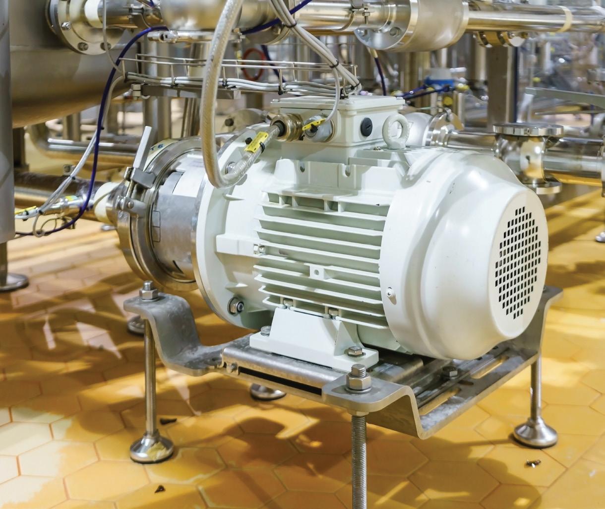
For marine applications, it is normally recommended for the casing to be manufactured from leaded gunmetal or in some instances cast iron, the impeller from aluminum bronze, wearing rings from leaded bronze, and the shaft and sleeves from stainless steel.
Some pump applications are subject to high suction lifts or low NPSHA, which require more cavitation resistant materials to be selected. Testing indicates the following materials have an increasing resistance to cavitation, from least to most: cast iron, bronze, aluminum bronze, stainless steel and duplex stainless steel.
Positive displacement pumps
Most manufacturers have standardised their positive displacement equipment on a range of metallic, plastic and elastomeric materials designed to be employed in a majority of applications.
Due to its corrosion resistant qualities, stainless steel 316 is one of the most commonly used materials for general purpose positive displacement pumps. However, stainless steel may not be resistant to fluids with high concentrations of chloride and some acids. In these instances, especially in regards to critical components, where no corrosion is permissible, other materials such as P20, Hastelloy, ceramic, Monel or titanium may be necessary.
Plastic materials are used extensively due to their resistance to chlorides and acids in low temperature applications. PTFE is often used for gaskets and glands due to its chemical inertness which makes it particularly popular for food and beverage applications since it does not harbour bacteria and is therefore not a source of contamination.
Elastomeric materials are specifically used for diaphragms, glands, seals, pump stators, rotors etc. due to their compatibility. On the other hand, high alumina ceramic is ideal for pump plungers, valves and mechanical shaft seals with its extreme hardness and corrosion resistance.
Further information and detailed diagrams, equations and schematics can be found in the Australian Pump Technical Handbook, available from the PIA website. In the next edition of Pump Industry, we continue to explore pump materials.

The pump industry relies on expertise from a large and varied range of specialists, from experts in particular pump types to those with an intimate understanding of pump reliability; and from researchers who delve into the particulars of pump curves to experts in pump efficiency. To draw upon the wealth of expert knowledge the Australian pump industry has to offer, Pump Industry has established a panel of experts to answer all your pumping questions.
This edition of Ask an Expert will look at pump monitoring and its influence on efficiency, downtime and lifecycle costs. At SEEPEX, our primary focus is naturally with progressive cavity pumps, but the principles described below are applicable to many different pump styles and process applications.
Q: How will pump monitoring shape the future of the pump industry?
A: Monitoring solutions with sensor-equipped pumps will soon be standard within many plants throughout all industries. The reasons for this are many and varied. Some examples include: lowering energy consumption, maximising efficiency and reducing TCO (total cost of ownership), as well as pumps installed at remote locations, with each consideration requiring its own unique monitoring solution. Monitoring process-critical factors in order to reduce maintenance times and streamline personnel allocation is crucial in numerous industries to guarantee plant availability and productivity.
Q: How does pump monitoring work? What are its benefits?
A: Speaking from first-hand experience, technology leading progressive cavity pump manufacturers have developed digital monitoring solutions to streamline operations. As the name suggests, these solutions monitor operating data via sensors attached to the pump, thus permanently checking pressure, motor speed, temperature and other parameters. All read-out data can be accessed in real-time via smartphone, tablet or in the control room.
Monitoring solutions pave the way for having operating data available at all times in all places. The plant operator can conduct analyses in the cloud to detect wear at an early stage and avoid process failures before they occur. With this technology, it is much easier predicting and scheduling inspection or maintenance work. In short: regulate your pump at the best operating point, optimise service and maintenance work and increase system availability.
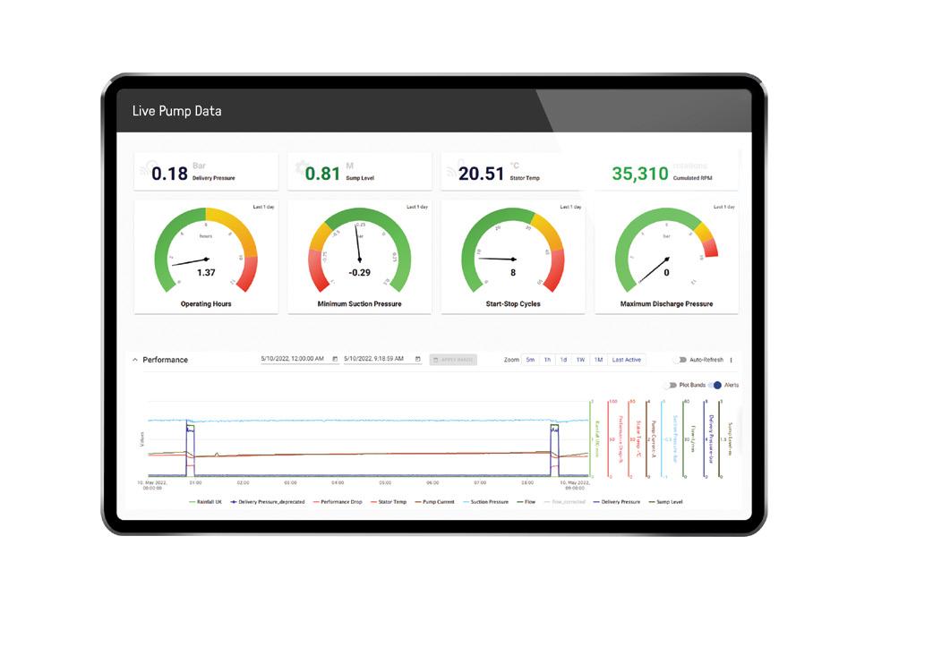
Q: How does monitoring help to lower TCO?
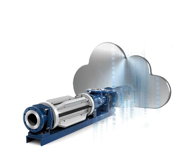
Some monitoring solutions give you the ability to configure alarm levels and be notified in your control room or on any smart device when they are exceeded. This allows you to intervene immediately and avoid costly downtimes, allowing predictive maintenance. Further, online pump characteristic curve adjustment, anomaly detection algorithms and the pump manufacturer’s expert knowledge optimise pump operation and processes.
Q: Is it safe to store data from my pumps and processes?
Premium pump manufacturers work with well-known big players in data storage, such as Google, to protect all workflows, processes and data from unauthorised access. A secure online connection and reliable cloud data storage that conforms to international security and data protection standards is as safe as it gets. Additionally, the customer determines what kind of data is recorded.

Q: Why worry now about implementing digitalisation into my processes?
A: Digital pumps will be the norm in a few years. The intelligent monitoring solutions will make processes more flexible, dynamic and efficient. Improved knowledge about pump performance, lower maintenance costs and ultimately high operational reliability are unbeatable arguments that will be harder and harder to ignore.
Contact a trusted progressive cavity pump advisor now to receive customised and intelligent designs that offer you greater control over your processes.
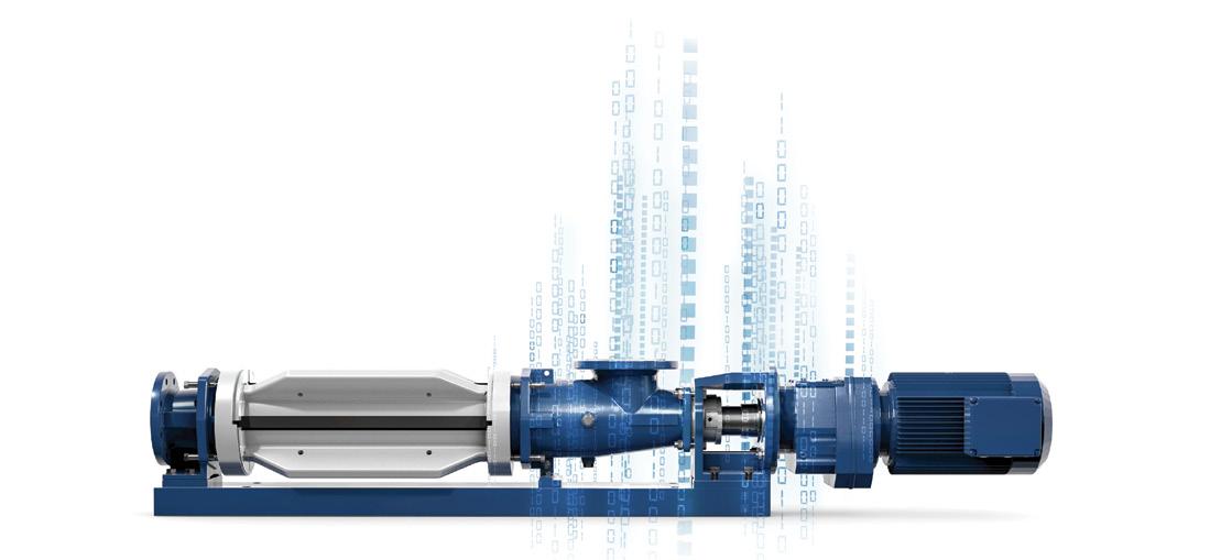
Peter Vila, Managing Director of SEEPEX Australia, is a progressive cavity pump expert. He has been involved with pumps for over 40 years. Peter spent the first five years repairing pumps and the following 35 years in technical sales, 20 of which have been with SEEPEX progressive cavity pumps.
For more information on progressive cavity pumps, please contact SEEPEX Australia on (02) 4355 4500 or at info.au@seepex.com
THE INTELLIGENCE OF THE PUMP PUMP MONITOR
Pump Monitor turns the progressive cavity pump into an intelligent field device.
y Performance analysis to optimise the pump and process
y Alarm notification
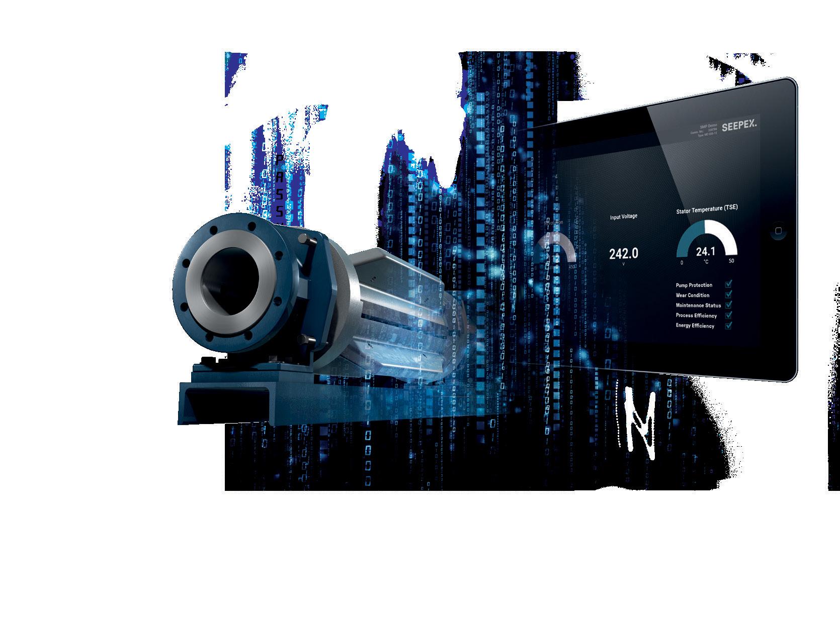
y Process protection through continuous monitoring
y Transparent pump performance
y Optimised operating costs
PUMP SCHOOL

There are three basic ways of controlling flow rate from centrifugal pumps. These are:
1. Throttling the discharge by closing a valve in the discharge line
2. Controlled bypassing of liquid from the pump discharge back to the suction vessel
3. Varying the speed of the pump
Discharge throttling
A basic principle of pumping is that a pump operates at the intersection of the pump performance curve and the system resistance curve.
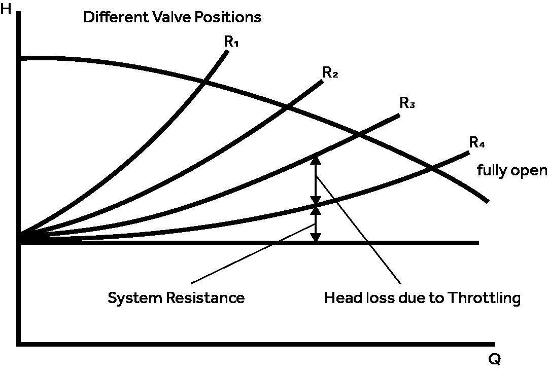
Throttling on the pump discharge by closing a valve (manual or automatic) has the effect of changing the system resistance curve. This changes the point of intersection with the pump performance curve with resultant change in flow. This is illustrated in the graph above.
Power consumption in a centrifugal pump is calculated from the formula:
Throttling wastes energy as pressure is broken down across the valve.
Bypassing
This is simply installing a line with a control valve (manual or automatic) which allows for return of some of the discharge flow to the suction tank. Opening the valve will increase flow to the suction tank and at the same time reduce flow down the discharge line. This also has the result of wasting energy.
Speed variation
Changing the speed of a pump changes the pump performance curve. This changes the point of intersection with the system resistance curve with resultant change in flow. This is illustrated in the graph below.
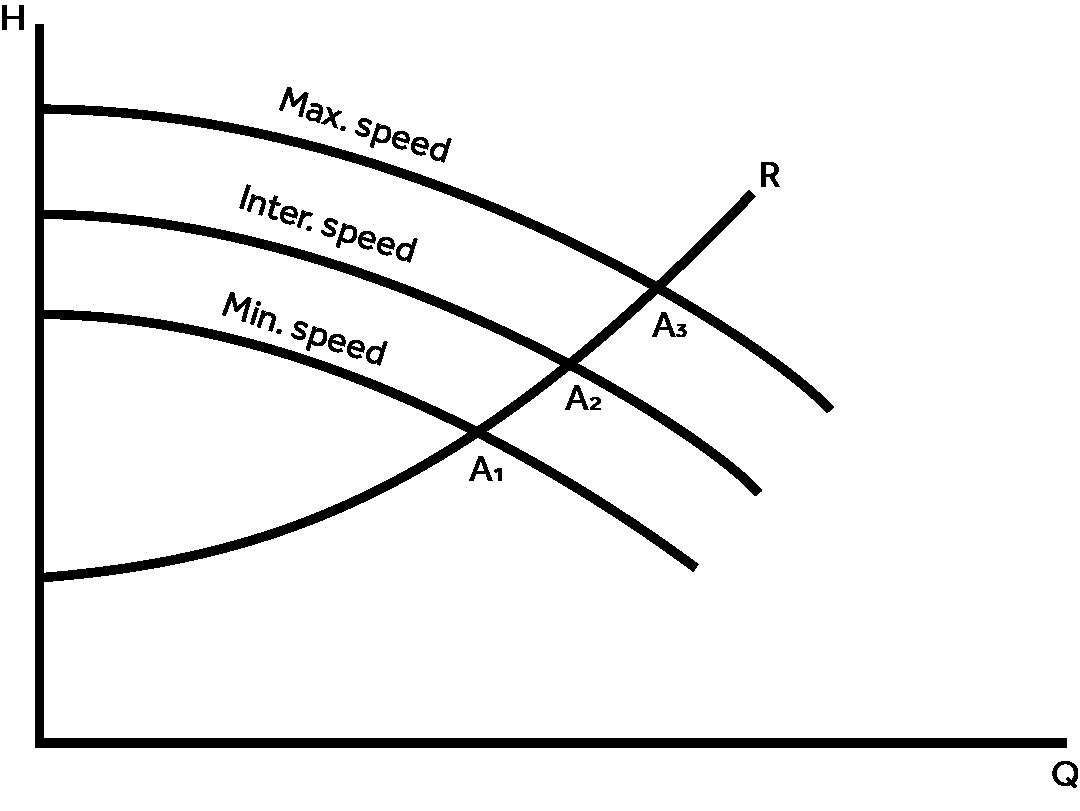
This is the most energy efficient method of controlling flow and becomes economically very attractive for larger power consumption installations.
In B2B, the sales cycle is long. You’ll always have people at different stages of the buying cycle, so your marketing needs to be always on.

Decision makers in the pump industry gain information from a wide range of sources. The team at Pump Industry are able to provide a complete range of marketing solutions:
● Brand building
● Educating the market
● Generating leads
● Creating engaging content
● Managing your social media and SEO
● Setting up marketing funnels
We also have a team of editors, designers and marketing experts who specialise in the pump sector and can help make the most of your campaign.
Scan this code to learn how we can help you ensure your marketing is always on.
www.pumpindustry.com.au

Editorial schedule
Secure IBC storage & decanting solutions
Polymaster’s unique Enclosed IBC Bund solves many of the problems associated with IBC storage and chemical/fluid decanting in a weather resistant, purpose-built enclosure.
Æ Full weather protection – stops rain entering the enclosure
Æ Easy forklift loading with wide forklift access from both side and back
Æ 250ltr day tank
Æ Lockable cabinet to keep system secure
Æ Venting by two sides
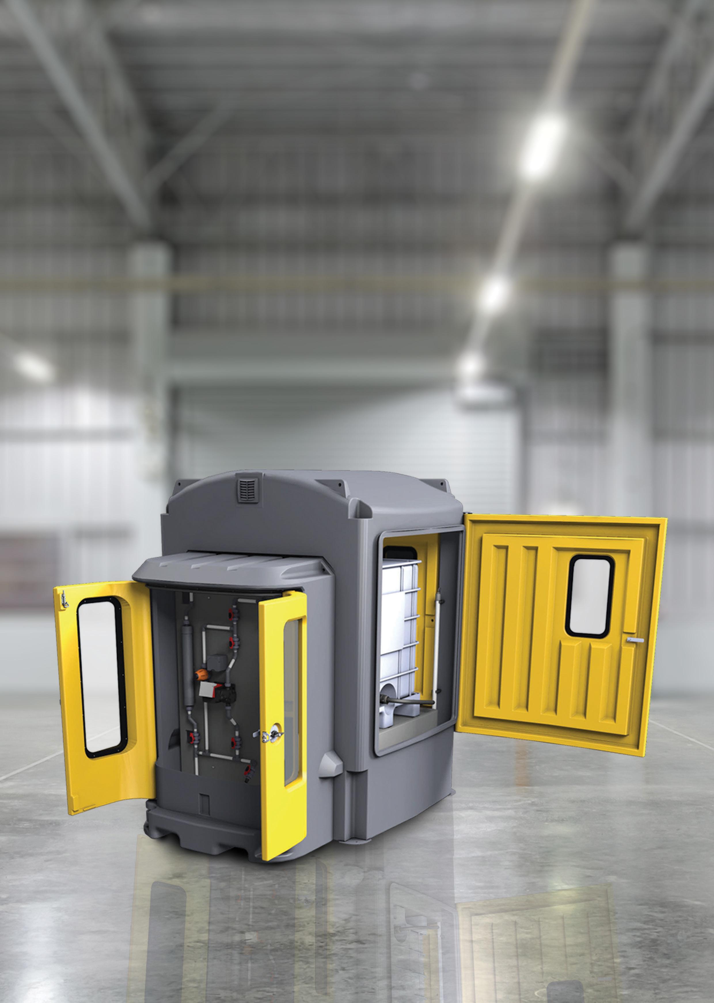
Æ Viewing windows incorporated into the doors
Æ 110% bund capacity complies with AS3780
Æ Sight tube and low-level alarm available
Æ Chemical resistant – high grade polyethylene construction

MHQP Series
FPS ISO Series
Designed for both industrial and agricultural application
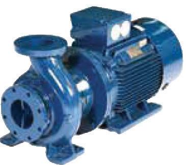
Multistage versatile pump set, combining and FPS MH pump with DrivE-Tech
Pioneer Series
Large Range of Heavy Duty Dewatering Pumps, Auto Self Priming, Wet Self Priming and End Suction Centrifugal, Solids Handling & abrasion resistant pumps.
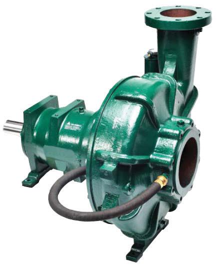
HWR Series
Wear-resistant pumps manufactured with highchrome white iron to maximize resistance against destructive abrasives and maintain peak performance in light slurry applications.
Fhoton SolarPAK
All in one, optimal preforming high-output package, containing a submersible pump and motor.
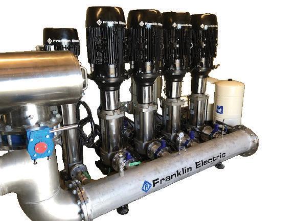
VR Series Multistage Pump
Vertical multistage pump booster and pressure system, designed in various combinations to suit, whether it be Industrial, Building Services, Commercial, HVAC, Domestic or irrigation applications. Ranging from a singular pump system through to a complex 8 piece design.
Dandenong South Facility: 106-110 Micro Circuit, Dandenong South, Victoria, 3175 Telephone: (61 3) 9799 5000

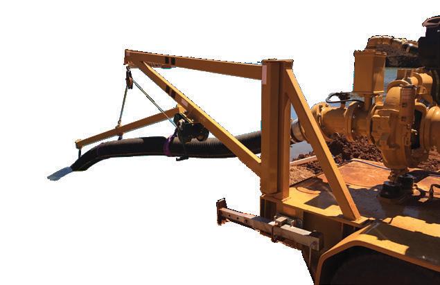
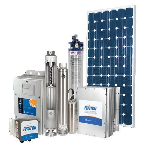
Sunshine West Facility: 1-67 Proximity Drive Sunshine West, Victoria, 3020 Telephone: (61 3) 9988 1650
