5 minute read
HDD construction methodology insights
Maxibor prepares an HDD construction methodology which provides a comprehensive overview of the processes involved in the physical delivery of the project and to demonstrate to stakeholders how key activities and issues specific to the project are to be managed.
This article provides an insight into reaming, hole conditioning, product pipe installation and testing for a typical 500 m large bore project installing OD500 HDPE pipe.
Pilot hole construction, reaming and hole conditioning
The expected ground conditions based on the geotechnical investigation is: • Drill set up for 60 m – OTR Clay • 60 to 140 m – bluestone with quartz (hard rock) • 140 to 207 m – transition from bluestone to mudstone/siltstone • 207 to 450 m – mudstone/siltstone • 450 m to exit at 500 m – transition from mudstone/siltstone to OTR
As the pilot hole will encounter both OTR and rock, the key bottom hole assembly (BHA) tooling will include: • 6.5 inch (165 mm) pilot hole drill bit • Jetting assembly • Orientation sub for mounting survey probe • P2 pressure module • 4 inch (101 mm) non-magnetic drill collar • 4.5 inch (114 mm) 5:6 motor for the rock sections
Following completion of the pilot hole, the BHA will be removed at the exit location and the first reamer attached. The proposed reaming sequence for the pipeline will be conducted as follows: • 500 mm back-ream • 750 mm back-ream • 750 mm hole conditioning pass
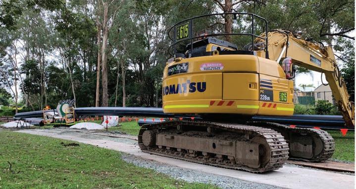
Excavator support operation during HDD installation.
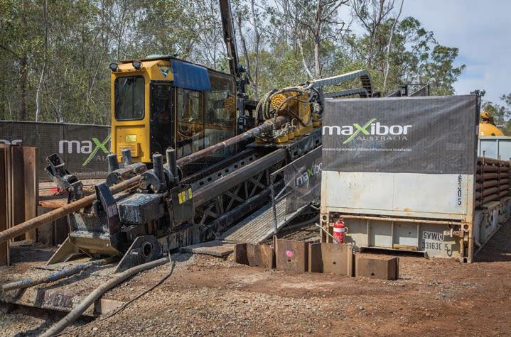
Maxibor drilling at the Logan Water Project. The hole conditioning passes will confirm the bore is in a condition to accept the product pipe. The driller will monitor and record drilling pressures, and the mud technician will monitor and record fluid properties so an accurate assessment can be made of the hole condition prior to installation.
Detailed bore logs will be maintained throughout the drilling processes. A drilling summary will be provided detailing the tooling used at each stage and relevant commentary particularly around the bore hole cleaning processes.

Product pipe installation and testing
Following hole opening and the completion of any required cleaning passes, pipeline installation will take place. As this is one of the most critical phases of construction, a site-specific installation plan will be developed which will cover daily schedules, pipe stress analysis, over bend dimensions, risk analysis and contingency and emergency procedures.
This will be reviewed and approved by Maxibor management prior to installation taking place.
The pulling head on the pipeline will be connected to the drill string using a 150 t rated maxi dub swivel. Attached to the swivel will be a 30 inch (750 mm) barrel reamer.
The drill string and barrel reamer will be free to rotate during the subsequent pipeline installation operation. The jets on the barrel reamer will allow bentonite drilling fluid to be pumped through the borehole during the installation operation.
The gravel shield will be installed over the rear of the reamer, swivel joint and the leading edge of the carrier pipe to prevent loose material falling in behind the reamer. This provides a smooth transition between the rotating and non-rotating parts of the assembly.
For buoyancy control, water will be pumped into the pipeline from the rear of the pipe string using a 50 mm pipeline and fill pump located at the rear of the site. A meter will be used to ensure that only the section of pipe below ground is filled so as not to cause excessive loads and stress on the above ground section of pipe.
Detailed engineering will determine the expected pull back loads and the fill and pull speed graphs for the project. An overbend will be formed using rated excavators and rollercradles to lift the pipeline and into a predetermined geometry which will ensure the pipeline enters the borehole in a smooth curve with no pin points that could cause a kink in the carrier pipeline.
The overbend bend radius will be kept as small as possible to stop overstressing the pipe. The pipeline will be supported on land using 20 t capacity pipeline rollers to support the pipeline above the ground surface during the pullback operation.
The rollers are typically placed every 12-15 m and an excavator is used to control the pipeline tail as it moves between rollers during the pullback installation. During the installation of the pipeline, large volumes of drilling fluid may be displaced from the borehole, so onsite storage facilities will be used in conjunction with the use of semi-trailer tankers to remove the drilling fluid.
Upon the completion of the pipe installation, the pulling head will be removed. The stub flanges and stainless-steel backing rings will be attached to each end to allow for the post installation hydrostatic testing to be completed.

Maxibor onsite at the Logan Water Project.
Maxibor is a knowledge sharing organisation. David Turner can be contacted on 0499 375 511 if you would like to learn more about Maxibor’s HDD Construction Methodology and its other good practice HDD design and delivery processes.
50 YEARS ... 50% OFF ... 50 DAYS ... SPECIAL OFFER ... HEATH SERVICES
Heath first came to Australian shores 50 years ago offering gas leak surveys along the Eastern seaboard. Today, 50 years later, 100% Australian owned, we are pleased to serve major Australian gas utilities, government departments, regulators, local councils and a large number of small businesses.
We still conduct gas leak surveys though it's fair to say technology has dramatically improved over recent years. Now we use tuned-laser and infrared gas detectors in the field, as well as the amazing EyeCGas fugitive emissions camera. We perform the bulk of our survey activities with vehicle or drone mounted equipment - 'Walking the line' is a distant memory!

We trust only a few brands to meet our client's safety and legislative requirements, and that's why we are the exclusive Australian distributor for: Ÿ GMI gas detectors (all configurations and capabilities) Ÿ Heath gas detectors (tuned-laser, Infrared, detection ranges up to 30m) Ÿ Opgal optical gas imaging cameras (cooled thermal, OGI with a range of up to 100m)
For the next 50 days*, we are offering 50% off the cost of rental for any gas detection equipment from our GMI, Heath, and Opgal hire fleets. Availability is limited, so please book today.


