
22 minute read
Design and Operation of Barroso Flyingbelt
This paper is a comparison between design data and operational data of the
Barroso Flyingbelt, the longest conveyor belt in the world suspended on ropes. The Flyingbelt is in operation in a cement plant in Southeastern Brazil and is transporting about 1 500 tph of limestone from the quarry to the factory – an output that would require a
Advertisement
minimum of 40 trucks Alberto Contin Matteo Colombo Stefano Cattaneo
per hour. Utilisation of this technology significantly reduces road traffic and CO 2 emissions The world’s longest aerial belt conveyor utilises a single 15 000-metre-long rubber belt as well as 60 000 metres of rope and 25 000 rollers.


Acement manufacturer launched the “Barroso Expansion Project” in 2012, this was a large investment, with the target to increase production capacity of the Barroso cement plant from 1.2 Mtons of cement per year to 3.6 Mtons per year. The demand for limestone required the supply from a new quarry, located 15km (by road) from the old quarry and the cement plant. A new raw material conveying system was needed and this typology of aerial belt was selected as the best option because it was perfectly suitable to overcome challenges associated with a conveyor system such as: • Minimisation of Capex: No land purchase + Less steel structures + No forest cut + Limited civil works • Minimisation of environmental impact: Low visual im
pact: the aerial conveyor is a “line” suspended with 18 support towers. • Maximisation of availability: using commercial and reliable components normally used for traditional conveying systems (belt, rollers, transoms, roller bases, drives, etc). • Customisation of the system: transfer points were designed and manufactured according to mechanical, electrical and safety requirements from the customer. • Integration of control system: the Flyingbelt is controlled by a PLC and it can be integrated in the Scada system of a “Crusher-to-Mill” transport chain, together with equipment from other OEM suppliers. • Minimisation of Opex: The aerial belt has similar operational costs of a conventional overland conveyor. The main challenges of the project were: the high capacity
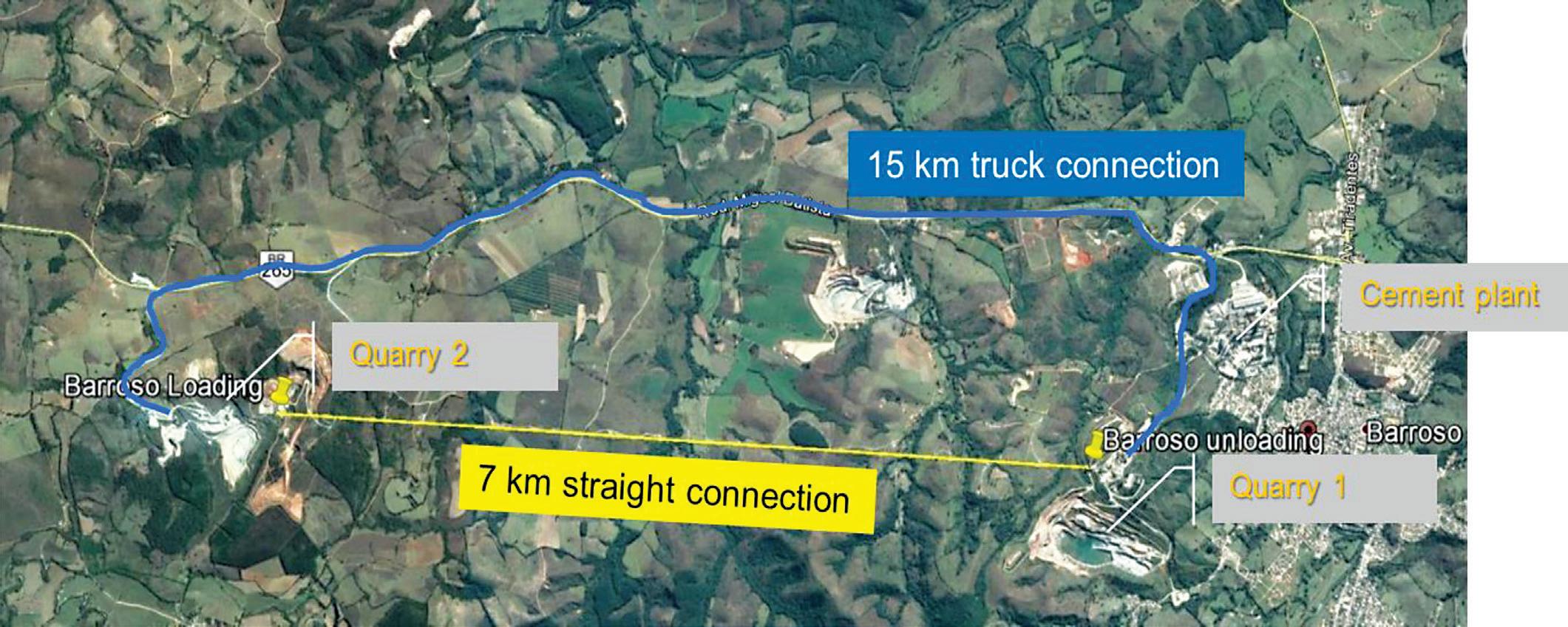
(1 500 tph), several geological and environmental constraints, the need for a “suspended” solution not to impact a preserved area, no transfer, no fencing and/or surveillance along the line, easy inspection and maintenance intervention along the line.
Description Diameter Mass Section Elasctic Modulus Minimum Breaking force Locked coil rope with "Z" shaped wires [mm] 55
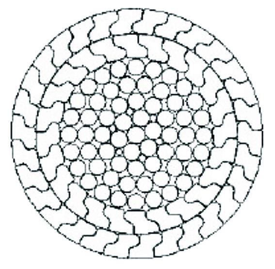
[kg/m] [mm 2 ] [N/mm 2 ] [kN]
17.0 2057 160000 2703
Figure 2 Tracking ropes characteristics
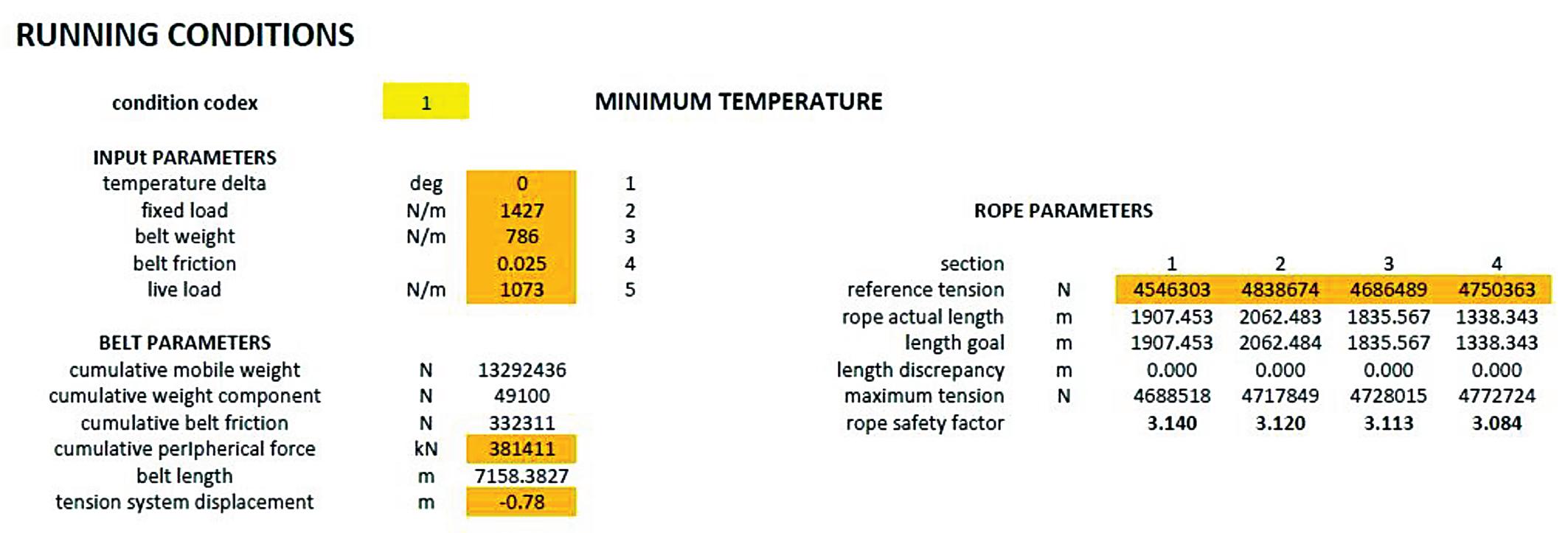
The solution proposed by the supplier is the result of a fully customised detailed study carried out by the supplier’s engineers specialising in several fields, such as: rope design, belt analysis, mechanical design, geological analysis, constructability analysis. This study was carried out following guidelines for material ropeways (OITAF book 8) and for conveyors (CEMA 7th), using software specifically developed by the supplier to simulate the static and dynamic behaviour of the system in different conditions (start-up, shut-down, normal operation, emergency stop, partial load operation). Main technical data of the Barroso aerial belt are as follows: • Material Limestone / Clay • Horizontal Length 7 200 m • Difference in Height 50 m • Belt width 1 200 mm • Track ropes 55 mm • Hauling ropes 20 mm • Number of towers 18 • Number of intermediate anchors 3 • Motors nominal power (belt) 3 x 615 kW • Motors nominal power (maintenance vehicle) 4x30 kW

• Speed of belt 4.00 m/s In the following paragraphs it is explained the way ropes and belts have been calculated.
Description Diameter Mass Section Elasctic Modulus Minimum Breaking force Redmont 6k19 (6 x k19 S - SFC) [mm] 20
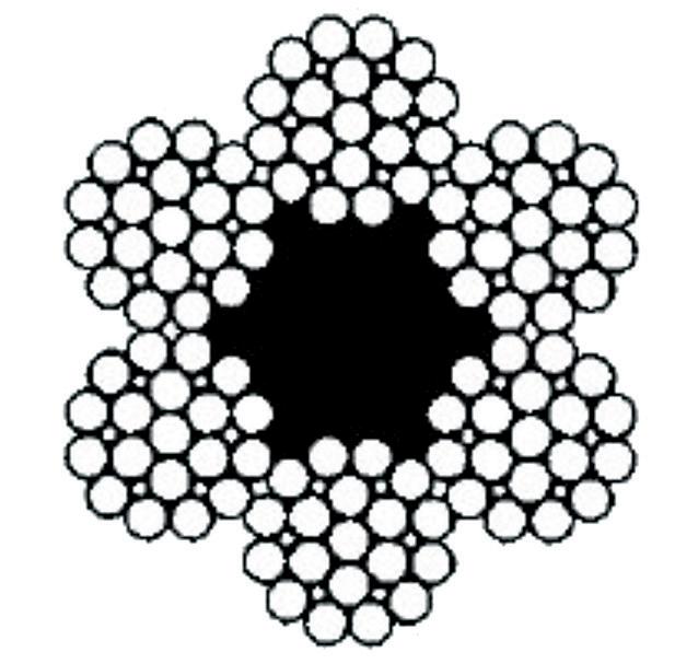
[kg/m] [mm 2 ] [N/mm 2 ]
1.60 180 125000
[kN] 272
Figure 3 Hauling ropes characteristics
Table 2 Analysis of hauling rope in nominal conditions
Rope line calculation
This aerial conveyor is a traditional conveyor suspended on ropes anchored on both ends (loading/tail station and offloading/head station). The choice of track rope construction form, size and mechanical properties is the result of a detailed analysis performed in several conditions: • minimum temperature, loaded belt • maximum temperature, loaded belt • minimum temperature, empty belt • maximum temperature, empty belt • loaded belt + max wind on service (250 Pa) • empty belt + max wind out of service (1 200 Pa) • mounting conditions (bare ropes, line frames installation) The operating temperature range taken into consideration is 60°C. Track ropes comply with the guidelines by international standards (*) about material transportation; according to these, the minimum track rope safety factor is: • On service, without wind: ≥ 2.50 • Out of service, with wind (1 200 Pa): ≥ 2.00 • On service, with wind (300 Pa): ≥ 2.50 (*) O.I.T.A.F., book no. 8, § 2.1.6.2, edition 2016, which states a minimum value of 2.50 on service. Concerning out of service + wind condition, the minimum admissible safety factor for material transportation is 2.00, proportionally derived from EN 12930:2015, § 7.4.2. Track rope suitable for the installation is of a locked coil type, with two layers of “Z” shaped wires, diameter 55mm; its main features are listed in figure 2. The calculation of the anchored track ropes implies the definition of a “reference condition”, which is assumed as a steady condition with empty belt and minimum ambient temperature. In this situation, an assigned tension is given to the track ropes, which is chosen in order to optimise the ropes behaviour and the running conditions. Starting from these assumptions, the calculation procedure obtains all the line parameters in the “reference condition”, with simple closed formulas assumed as known. In detail, the procedure calculates the “section cumulative actual length”, that is the length assumed by the rope lying on a horizontal plane, without tension and without weight. For each load condition (different temperature or different load on the belt) the procedure iterates the calculation several times, varying the track rope tension, ending the calculation when the new values of the “section cumulative actual length” equal the original reference length. For the purpose of line calculation, the full system is treated as a single anchored rope with the following assumption:
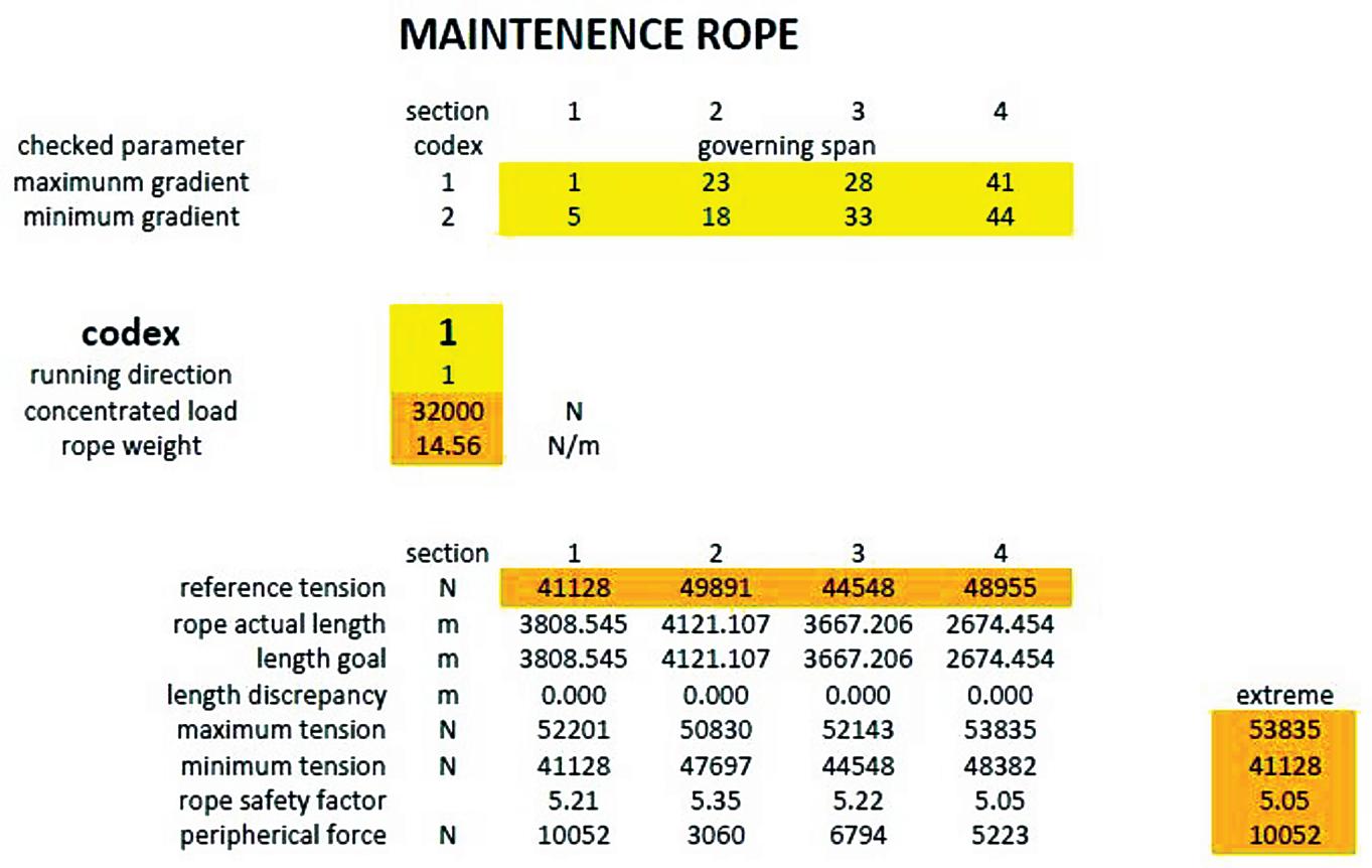
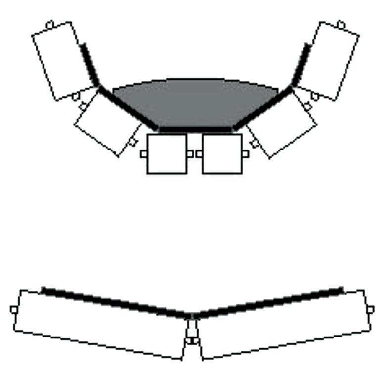
Figure 5 Wind effect
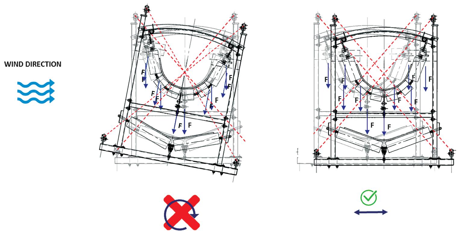
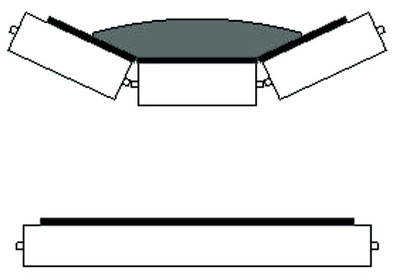
Figure 6 Traditional conveyor rollers
Figure 7 Loading station • equivalent rope tension equals the sum of track ropes • equivalent rope weight equals the sum of track ropes, suspended frames, rollers and miscellanea, carry and return side of the belt, bulk load on the belt The weight of the suspended frames and rollers is applied as a uniform load distributed along the track ropes; live load may be different in different spans, according to the load condition investigated. An example of track rope dimensioning is reported in table 1.
Haul rope calculation
Haul rope for maintenance vehicle is related to an emergency rope. It complies with the guidelines by European standard EN12927- 2 for people transportation; according to it, the minimum haul rope safety factor is ≥ 3.00 (reference: §5.2.1.6). Haul rope is closed in a loop with two socket end fixings, which are connected to the hanger pin of the vehicle. Haul rope is a Redmont 6k19, diameter 20mm; its main features are listed in figure 3. An example of haul rope dimensioning is reported in table 2.


TRANSNET FREIGHT RAIL
www.transnetfreightrail-tfr.net
Belt conveyor line calculation
The choice of the belt conveyor is the result of static analysis performed in six different conditions: • minimum temperature (-20°C), loaded belt • maximum temperature (40°C), loaded belt • minimum temperature (-20°C), empty belt • maximum temperature (40°C), empty belt • worst starting condition (with an inclined section loaded
and minimum temperature) • worst braking condition (with a declined section loaded and maximum temperature) The layout of the track ropes is set as input for the belt calculation; the rope configuration corresponding to maximum temperature and loaded belt is prudently considered for all conditions. The belts comply with the limits imposed by the manufacturer (eg, safety factor, minimum radius in vertical convex curves,
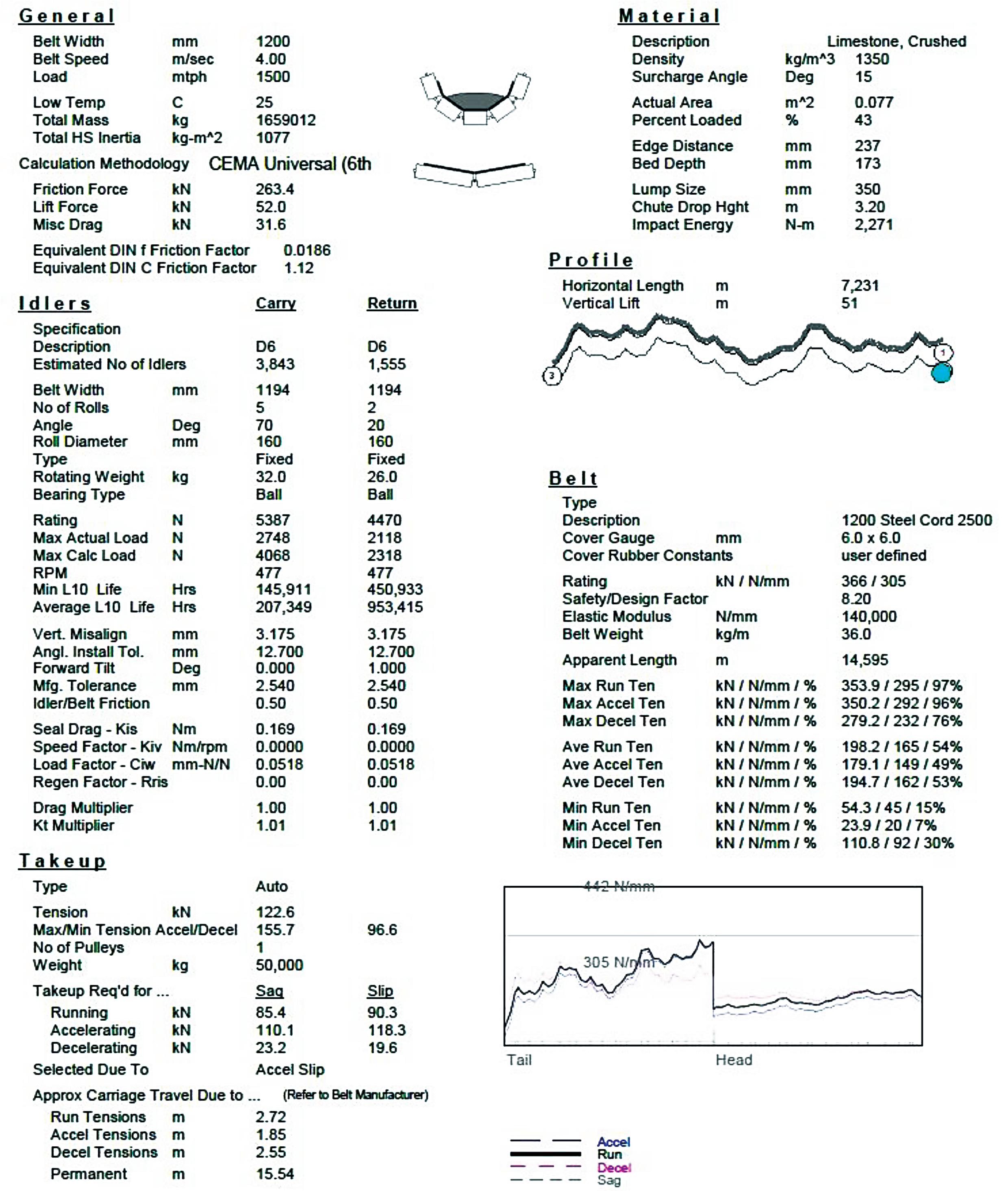
transition distances, turnover lengths …), in detail: • average running (laden belt or empty belt) safety factor: ≥ 6.67 • average transient phases (starting/stopping) safety factor: ≥ 4.60 • local transient phases (starting/stopping) safety factor: ≥ 4.00 The dimensioning loads and factorisation of belt tension along the turnovers was subject to and approved by the belt manufacturer, considering also the beneficial effect of the high splicing efficiency foreseen for this application. The idlers on the carry side are 6-roll garlands with a 2.0m

spacing, while on the return side they are two-roll garlands, with 6.0m spacing. The 6-roll garland was selected for its 70° troughing angle able to maximize the stability of the system: the material is kept in the centre of the system, with a resulting mass-centre than the geometrical-centre. This configuration is maximising the stability of the system in all the load configuration also in case of high side wind: On towers, the garlands on the carry side and on the return one are replaced respectively by three-roll and one-roll fixed frame idlers, reducing their spacing, in order to enable vertical convex curves with a radius of 75m. The troughing angle of the carry side on towers is 25°, in order both to reduce local tension on the edges of the belt and to avoid compression in the middle; the filling factor and the edge distance with 25° troughing angle are respectively 61% and 187mm, avoiding any risk of material spillage. Belt line calculation is performed according to CEMA 7th – Universal method, using the software Belt Analyst, written by Overland Conveyor Company Inc. The belt of the aerial conveyor is computed according to the following data: • Load capacity: 1500 mtph Belt speed: 4.0 m/s Belt width: 1200 mm Bulk density: 1350 kg/m 3
Surcharge angle: 15° • Maximum lump size: 300 mm The resulting filling factor (for 70° troughing angle) and edge distance are respectively 43% and 237 mm. The belt is tensioned by a gravity take-up, which is installed in the head station. Two drive pulleys are installed in head station, while one drive pulley is placed in the tail station. Each drive pulley has one motor; the motor and gear unit type is the same for all drive pulleys. Each drive pulley has a wrap angle of 210° and ceramic
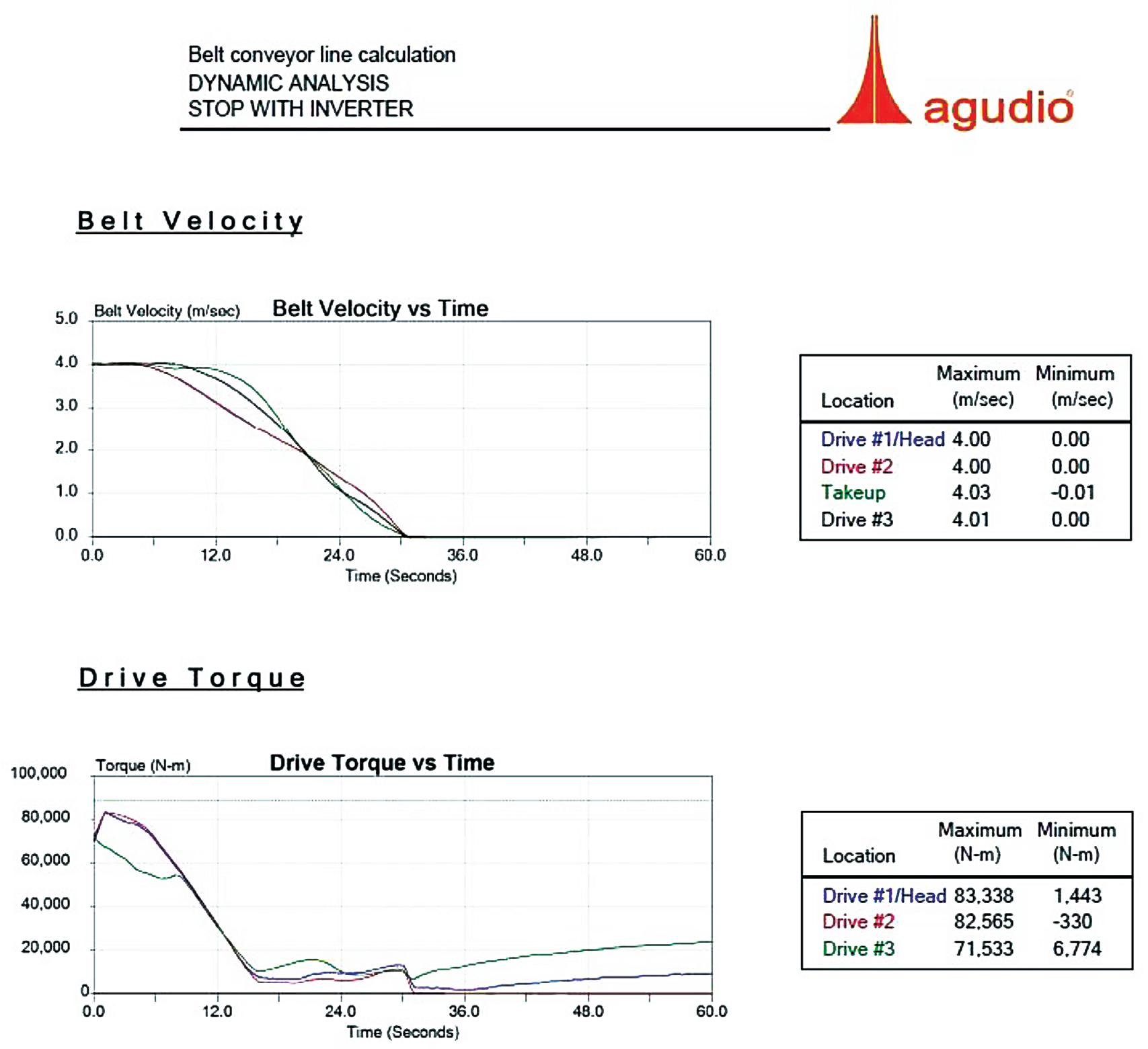
lagging, in order to ensure drive friction. The belt is calculated considering 160s start time, while the stop of the belt, using only the electric motor, occurs in 30s. In order to take into account the behaviour of the belt during transient phases (start/stop), a detailed dynamic analysis is performed.
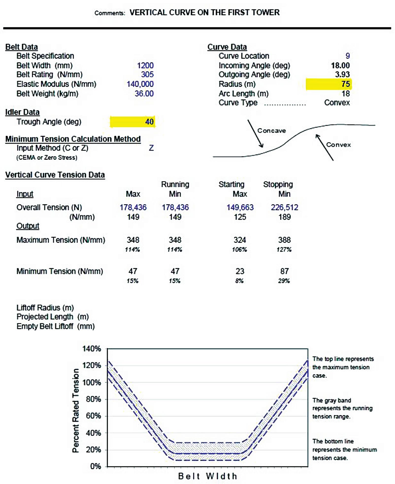
Table 5 Belt tensions in concave and convex curves All garlands have Ø159mm steel rolls. Idler to belt friction coefficient is 0.50. An example of belt dimensioning is reported below.
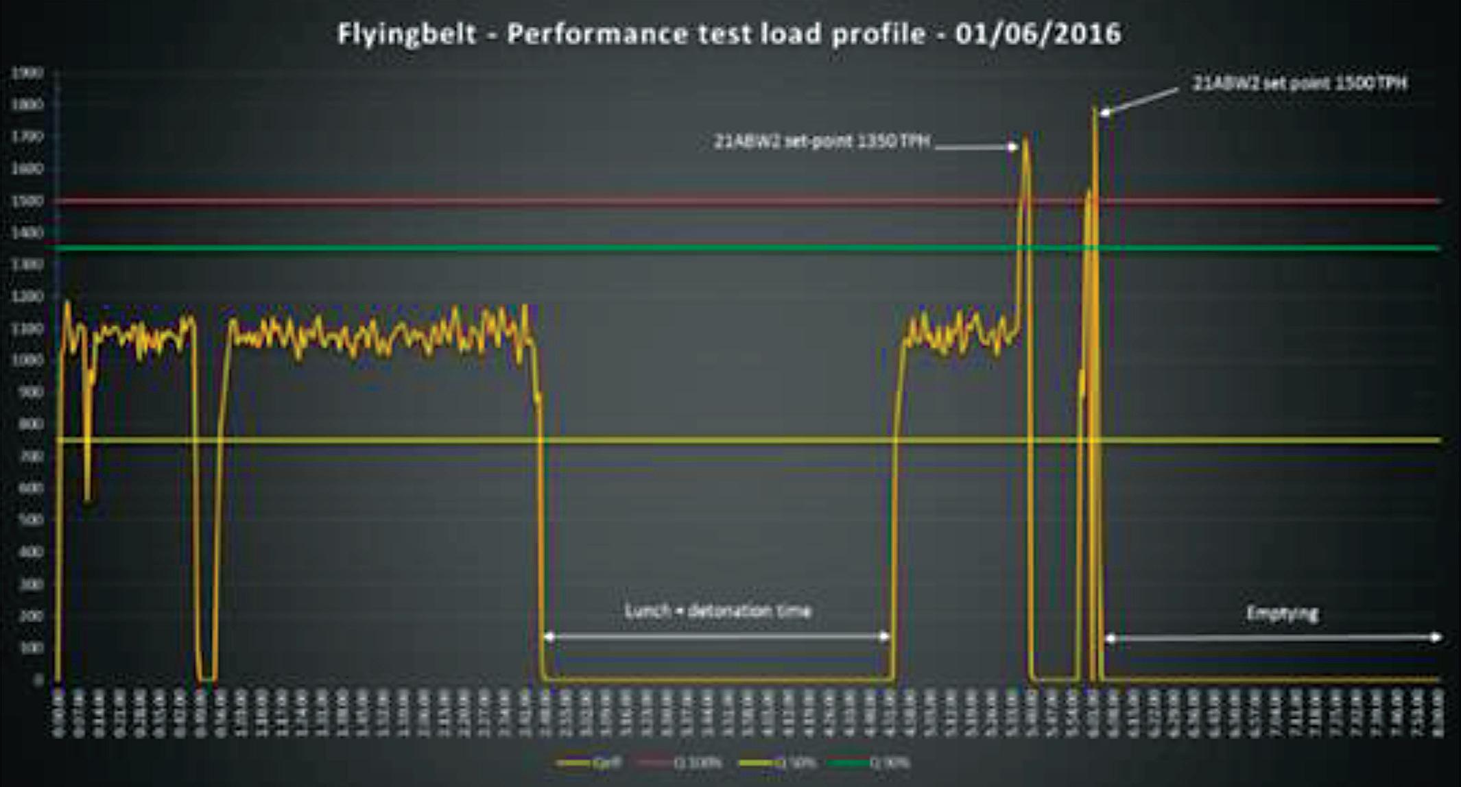
Conclusion
The result of the study on the longest aerial belt in the world composed of one single belt of 14.4 km running from the loading station to the unloading station suspended by 4 segments of tracking ropes (to reduce the construction time) through 18 supporting towers at a speed of 4 m/s. From May 26th, 2016 and June 1st, 2016 the commissioning and start-up of the system has been done successfully demonstrating the operational parameters vs contract requirements, in particular: 1 500 Tph max. capacity (even if normal operation capacity will be 1 000 Tph) and max. power consumption of 1 750 kW. The conveyor has been tested in the following conditions: • Loading • Constant feeding • Raise to nominal capacity • Drop of capacity • Overloading • Emergency stop During the first 8 months of operation, real operating data has been collected and compared to the design parameters, the result is the following: The above data, even if for a limited number of operating time per day compared to the theoretical use, demonstrates the compliance with the design parameters, in particular 1,15 kWh/ton means, assuming a
Month June July August September October November December January
TOT
Average Tph 1.026 949 1.035 1.142 1.073 991 1.015 1.021
1.037
Load percentage 68,4% 63,3% 69,0% 76,1% 71,5% 66,1% 67,7% 68,1%
65-75%
Tons transported 12.183 2.961 35.304 32.401 83.615 54.892 82.303 65.138
368.797 Power consumpion (kWh)
14.010 3.405 40.600 37.261 96.157 63.126 94.648 74.909
424.116
cost of 0,12 USD/kWh, 0,138 USD per ton transported, a very competitive value considering that the consumption includes the inspection along the line with the maintenance vehicle.
Moreover, no spare parts or maintenance intervention has been done in this period and only six people are required during the operation (2 in quarry main control room + 4 for maintenance of the whole crushing and conveying).
This paper was first presented at the Beltcon Conference in 2019. Copyright is vested with IMHC. www.beltcon. org.za Alberto Contin LEITNER SpA – Office Leini Tel: (011) 997-3355 alberto.contin@agudio. com www.agudio.com
Matteo Colombo Tel: (011) 069-1294 matteo.colombo@leitner. com www.agudio.com
Stefano Cattaneo Tel: (011) 997-3355 stefano.cattaneo@ agudio.com www.agudio.com
Table 6 Dynamic analysis of stopping cycle

The dream of every plant operator is to eliminate dust and spills on belts and transfers and to minimise maintenance requirements of the conveyor system. An added bonus is to be able to cope efficiently with the challenges of moist and sticky materials. BLT World’s contact-free Airscrape conveyor belt skirting system, developed by Scrapetec, has been designed to do just that. This highly-efficient system prevents dust formation, reduces material spill, enables thorough belt-cleaning and minimises the risk of explosion at critical sections along the conveyor route and at transfer points. An important advantage is that this system, unlike conventional systems, is also proven to work perfectly well with moist and sticky materials.
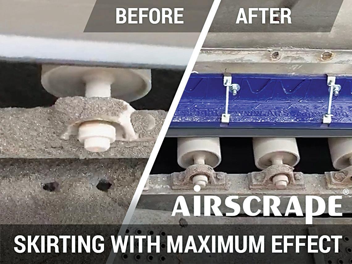
AirScrape is a highly-effective side seal that lies over the conveyor belt, without contact, and creates negative pressure on the belt, due to its speciallydesigned lamella structure. Because this system hovers freely above the conveyor belt, skirt friction The contact-free conveyor belt skirting system significantly reduces and belt damage is eliminated and service life of material spill, dust formation and explosion hazards at transfer points every component of the conveyor is extended. and other critical sections in the conveyor chain. The system also copes efficiently with the challenges of moist and sticky materials It has solved the problems of “moist and sticky” conditions in many industries. A perfect example of this 90% of the time previously spent cleaning, is now available system’s success, can be seen at a processing plant which for productive work at the plant. specialises in processing slag and ashes from waste incineration plants into usable raw materials. BLT world Airscrape’s six-week trial operation period showed that alKen Mouritzen, Tel: (031) 274-8270 though cleaning at critical points is necessary once a week, Email: ken@bltworld.com, www.bltworld.com
Dust Suppression
BossTek has introduced an optional Variable Frequency Drive (VFD) system that allows users to adjust air flow to suit a broader range of applications and working environments. The new VFD system reduces the need to purchase or rent different models to match the machines’ output to specific project requirements, delivering greater flexibility and reducing the total cost of equipment ownership. “Atomized mist technology has been widely accepted as an extremely effective approach to dust management,” observes BossTek Sales manager, Mike Lewis. “This new development will allow users to tailor the fan speed to match the job. It’s useful in a number of different industries, but one good example would be demolition projects,” he notes. “Project managers may need the wide coverage and long reach of our larger models on some jobs, but the volume and throw distance may be too much for smaller projects, such as those in crowded downtown locations. Instead of using a smaller machine to accommodate their changing needs, now they can simply dial back the air flow to match the requirements of those smaller projects.” The VFD is likely to be attractive to companies with variable needs, including concrete curing, cannabis and hemp operations, transfer
BossTek Rick Felde Tel: (541) 306-4815 Email: rick@bosstek.com www.bosstek.com
stations, slag handling and indoor applications.

Opening the doors of the mining sector to junior miners and emerging contractors can be boosted by partnerships based on the build-operate-transfer (BOT) concept, according to B&E International. Experts in integrated crushing, mining and mineral processing solutions, B&E International brings its experience of not just operating crushing plants but designing and manufacturing its innovative equipment locally, according to the company’s director of plant and engineering, Ken Basson. He says, "We have partnered with junior miners and emerging contractors to assume some of their initial risk in mining projects and giving them a firmer basis for sustainable growth.” He highlights that new entrants to the mining sector face both financial and technical hurdles. Sourcing a fit-forpurpose processing plant is frequently a ‘bridge too far’ in terms of capital expenditure. Financial institutions usually require a strong balance sheet, which many young companies do not have. There is also the risk that a new plant may not run smoothly or to specified capacity, demanding a depth of technical expertise not yet developed by a new contractor.
Ken Basson, director:plant and engineering at B&E International, says opening doors for juniors mines can be boosted by partnerships based on the BOT concept
“With our experience of running plants, combined with our inhouse design and manufacturing capabilities, we shoulder a large portion of this initial risk for the smaller players,” says Ken. “We design and build the plant to suit our BOT partner’s operational needs, and then run the plant ourselves. The partner pays us only for the final saleable product from the plant.” The arrangement is a close collaboration with the partner, who must be assured of meeting their contractual obligations to the end-customer. The production experience in B&E International, which has for decades run crushing and screening operations for its own account, is what puts their BOT partners’ minds at ease.

B&E International (Pty) Ltd. Tel: (011) 966-4300 Email: info@beinternational.co.za www.beinternational.co.za

Up to 50 units can be monitored by a single gateway connecting to the Internet Martin Engineering has announced a belt cleaner position indicator that monitors the blade, tracking and reporting remaining service life. The intuitive Martin N2 Position Indicator (PI) monitors primary belt cleaner blades, notifying Martin service technicians and plant operations personnel when re-tensioning or replacement is required and/or when abnormal conditions occur. The PI can be part of a new installation or directly retrofitted to existing mainframes that use the company’s replacement blades. Managers and service technicians can quickly access info on any networked cleaner via cell phone. With approximately 1 000 operating systems currently in service and installations continuing daily, the technology has been embraced by bulk material handlers in a wide range of industries and applications. Designed in-house by the engineering team at Martin’s Centre for Innovation (CFI) in the USA, the N2 position Indicator is produced solely in company-owned facilities to ensure the highest standards for quality control. In fact, the firm also engineered and built the proprietary equipment used to manufacture the new devices. Martin offers the equipment, monitoring service and batteries free of charge to qualifying customers. The company will also support the PI components and provide customer alerts without cost as needed, with mainframes and tensioners replaced free for users of Martin belt cleaner blades. Position indicators can be mounted anywhere from 3-800 metres (10-2,625 feet) from the cellular gateway, and the robust, sealed construction means it is virtually immune from damage. Up to 50 units can be monitored by a single gateway connecting to the Internet, usually located at the highest point in the plant, where the cell signal is strongest. The system does not require a cellular line for each PI, instead communicating via radio frequency from each sensor to the gateway. The device eliminates the need for manual inspections by giving technicians precise information, delivering critical realtime intelligence and reducing exposure to moving conveyors, improving both efficiency and safety.
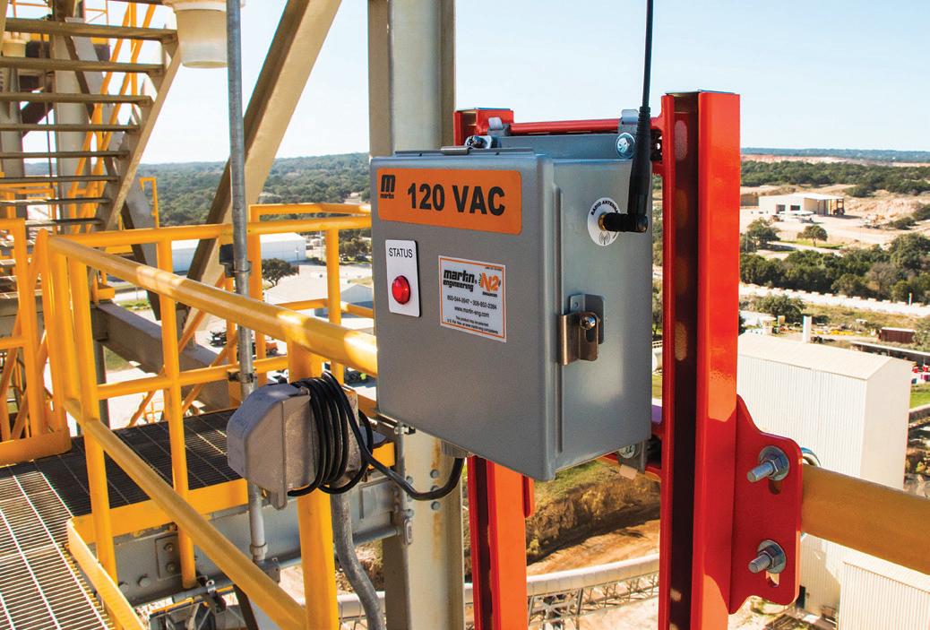
Martin Engineering Rick Felde Tel: (541) 306-4815 Email: rickf@martin-eng.com www.martin-eng.com
“The new high-torque, high-speed Tsubaki BS-F series, with a narrow width I-beam torque arm, is a drop-in replacement to conventional anti rollback devices. This allows for quick and easy on-site installation and enables the replacement of an old backstop with the new BS-F design, without the need for modification to the existing layout,” says Gavin Kirstein, National Tsubaki Product Specialist, BMG. “Although this series has a narrower width than other models, the downsized unit exceeds the requirements of high-speed inclined belt conveyors, with the benefits of space-saving and reduced installation time. “A common cause of conventional backstop failure is oil leakage. Tsubaki has eliminated this risk in the new BSF series by designing the backstop to operate with grease and a specially- designed labyrinth seal. The absence of an oil level gauge creates a more reliable safety device, " adds Gavin. “Important features of this series include a nonrollover cam and roller design, which offers higher backstop torque capacities and lower running temperatures than conventional anti rollback devices. Added to this, a flexible labyrinth seal mechanism prevents the ingress of dust and water in abrasive conditions and a double-lip oil seal and multi-temperature grease enable safe operation at a wide ambient temperature range, from - 40°C to + 65°C.” The cam and roller cage orbit at low speed, continually conveying grease internally from the bottom to the top of the mechanism. The constant circulation of grease minimises internal friction and reduces operating temperature for dependable operation. Maintenance intervals are between 7 500 hours and 8 000 hours and the effective service life of the units is also significantly extended compared with conventional oil-filled units.
BMG Carlo Beukes Tel: (011) 620-7558 Email: carlob@bmgworld.net or Gavin Kirstein Tel: (011) 620-7547 Email: gavink@bmgworld.net

An extensive range of cam clutches, is designed for high-speed inclined and long overland belt conveyors and bucket elevators used in mining and bulk handling sectors
Minerals

Your trusted partner of choice
For more information or assistance call us on +27 (0)11 9292600 or visit us on www.global.weir You can now buy your spares online at www.weirafricastore.com
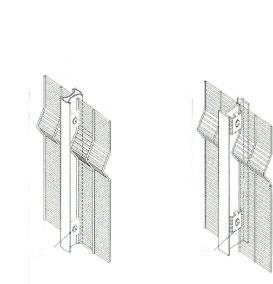
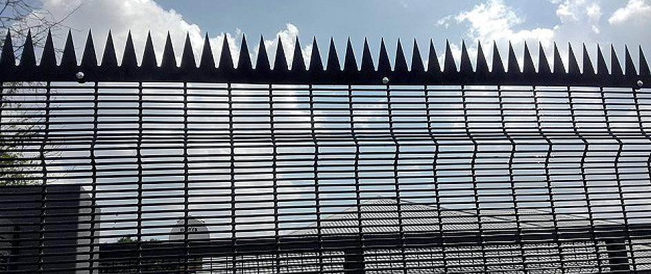
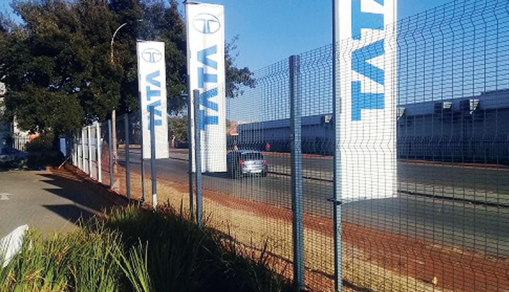
High security welded mesh Pallisade Gates Gate Automation Razor wire and more .... What is High Security Weld Mesh HIGH Security Weld Mesh is wire fused and welded at a Horizontal distance of 76.2mm and a vertical distance of 12.7mm also known as 35B/3510 where 3 denotes 3”(distance between vertical wires), 5 denotes 0.5” (distance between horizontal wires), and B or 10 denotes gauge of wire

Salient Features
• Difficult to Climb: The spaces between the Horizontal wires are too narrow for fingers to have grip • Impregnable: Extremely difficult to cut with a hand cutter as the beak of a wire cutter will not be able to penetrate the horizontal wires
• Excellent Replacement option to Solid Wall as:
1. More economical than a solid wall 2. Faster to install than a solid wall 3. CCTV Camera has a clear view
• Further upgrade possible with electric security system • Anti-corrosive & low maintenance
Standards
• Manufactured according to BS EN 10016-2 • Wire Sizes in accordance with BS EN 10218-2 • Tolerance on Mesh Size in accordance wiht EN 10223-7 • Tolerance on Panel Size in accordance with EN 10223-4 • Welding Strength in accordance with BS EN 1461 • Zinc Coating in accordance with EN 10245-1 • Anti Corrosion in accordance with BS En 3900 E4/F4

Tensile Strength
• Wire has a tensile strenght of min 550 MPA
MARK: 083 454 6488 Email: mark@palifence.co.za www.palifence.co.za


