7 minute read
Environment: Durr Systems
Generating electricity using glass production exhaust gas
Matthias Hagen* and Sven Jensen** explore the obstacles and opportunities of using excess heat from fl ue gases to aide improve sustainable glass manufacturing.
Major glass companies are currently looking for possibilities to reduce CO2 emissions.
As glass production is an energy intensive process, the main target is to reduce or replace the use of fossil fuels.
Kiln suppliers are shifting from fossil to electric fi ring and the use of hydrogen is an ongoing discussion. Regardless of the type of fuel used in the kiln, all furnaces will create fl ue gases with temperatures between 280 °C and 550 °C.
This temperature range depends on the installed heat recovery with recuperators or in most cases regenerators.
Experience shows that the composition of the fl ue gases and the dust content poses a constant threat to the equipment.
Internals of the regenerators, refractory parts called checkers, will clog and so the recovery of heat will be reduced.
Although periodical thermal cleaning helps to reduce deposits manual cleaning is required in the long term. This illustrates the diffi culties in handling dust containing fl ue gases.
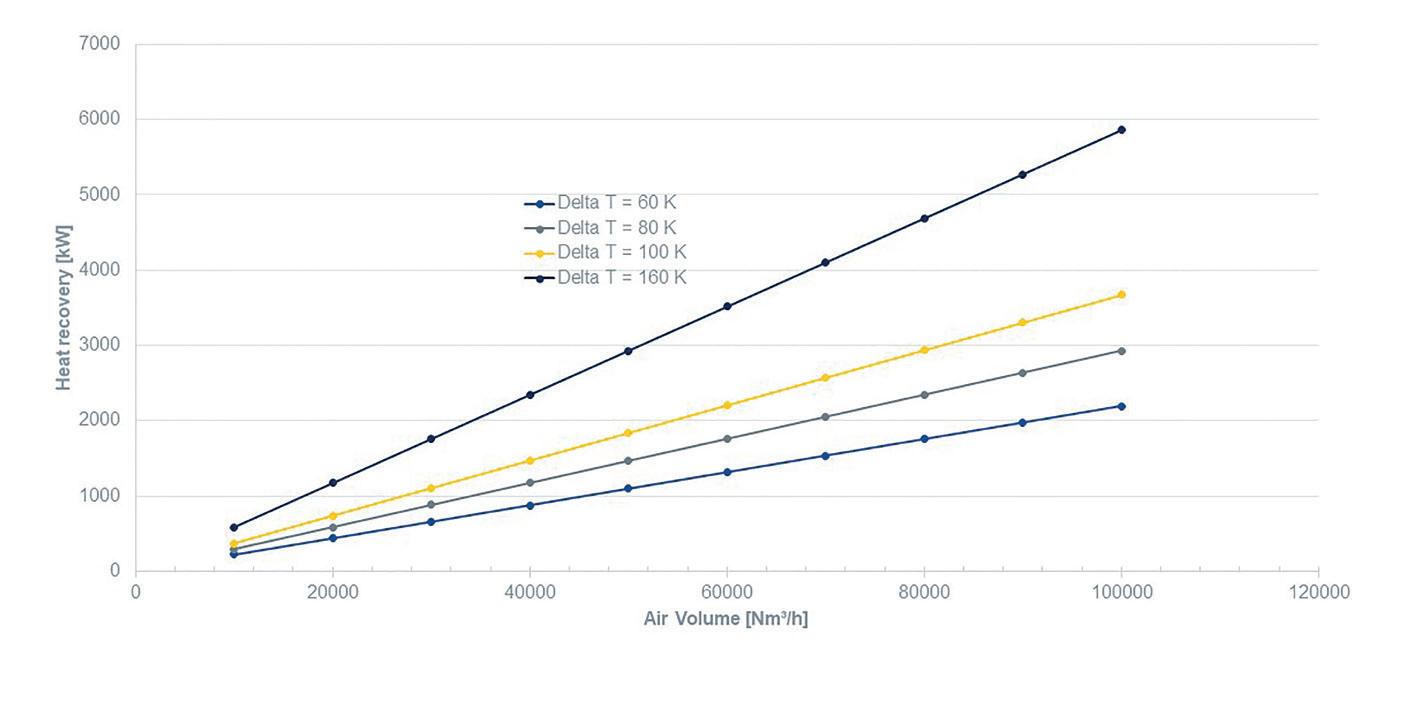
However, the exhaust gases represent a huge potential for energy recovery. In most cases it is not utilised today (Fig.1).
Typically, the thermal energy is dissipated to ambient due to cooling requirements for the fl ue gas treatment with a bag fi lter and sent to the atmosphere through the stack.
By installing a heat exchanger in the fl ue gas fl ow, valuable thermal energy
Exhaust gas volume fl ow Recoverable electricity
30.000 Nm³/h 45.000 Nm³/h 60.000 Nm³/h 250 to 420 kW 375 to 630 kW 500 to 840 kW
� Fig 2. Recoverable electric energy depending on the volume fl ow. � Fig 1. Chart of the heat recovery over air volume.
can be extracted and transferred to warm water or thermal fl uid.
But many glass factories do not have a direct use for it. The own requirement for hot water is small and in rare cases it is possible to feed into a district heating network nearby.
The ideal solution is the conversion of thermal energy into electric power. This is possible with an Organic Rankine Cycle
Continued>>
2
Evaporator Heat transfer from heat source to working media
1
Heat supply Heat transfer medium fl ows from the heat source into the ORC Module 3
Turbogenerator Thermal power is partially converted into electric power 4
Power generation Electric power feed line to the grid 5
Condenser Condensation of working media vapor
6
Heat extraction Condensation heat, that can be utilised for follow-up processes
� Fig 3. Principles of the ORC technology. 7
Pump Recirculation of the working media
� Fig 4. Best combination for CCF and ORC technologies.


(ORC) system, which is essentially an “upside down” fridge.
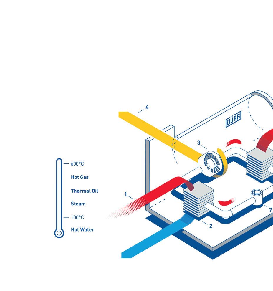
In a fridge you put in electricity and get out cold. In an ORC you put in heat and receive electricity (Fig. 2).
The ORC is a thermodynamic process similar to the wellknown water-steam cycle, which forms the basis of conventional electricity generation in power plants (Fig.3).
The main difference is that the ORC uses an organic fl uid with a low boiling point. Consequently, ORC is a key technology for generating electricity from heat sources with medium and low temperature levels.
In the glass industry in principle heat recovery systems can be installed in two different positions in the fl ue gas fl ow: one position is downstream of a bag house fi lter which usually operates at around 200 °C.
The other position is right downstream the regenerator where the exhaust gas temperatures are between 400 °C and 550°C. Each position is characterised by specifi c conditions.
The position downstream of bag fi lters yields the advantage of an almost dustfree environment. Dust deposition and fouling of heat transfer surfaces can be largely avoided.
At the same time several disadvantages must be named: The relatively low exhaust gas temperature leads to large heat exchangers with high costs.
Additionally, the conversion to electricity runs at a relatively low effi ciency at around 6 % to 9%.
In contrast, exhaust gases in the range between 400 °C and 550 °C enable ORC systems to deliver around 15% to 18% of the heat as electric energy.
Moreover, the residual heat of the condensing of the ORC working media after the turbine can be used as secondary
� Fig 5. Modular components of the ORC system. heat source with temperatures up to 90 °C if needed.
This secondary heat can make up to 80% of the primary heat and creates additional value for the owner when used for heating purposes on site or when fed to a local district heating network.
The major disadvantage of positioning a heat recovery system at the position upstream the fi lter is the high dust amount. Similar to well-known problems of fouling and clogging of regenerators the heat exchanger will suffer and the performance will degrade rapidly. Continuous intensive cleaning cycles are necessary or the installation of sophisticated but expensive additional equipment is required, such as a shot cleaning system. Steel balls pass through the heat transfer area from top to the bottom and, thus, maintain the surface area clean. In many cases the investment in the heat extraction and cleaning system exceeds the investment in the ORC system that leads to an unattractive business case.
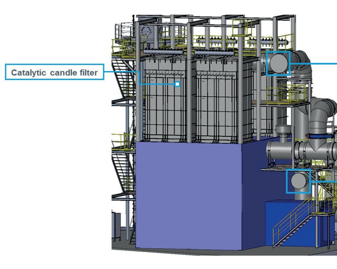
In this context, the innovative catalytic candle fi lter technology (CCF) combined with a heat recovery by means of an ORC system offers new possibilities (Fig.4).
Continued>>
� Fig 6. CCF with assembly studs for the ORC.
The advantage of the position of the ORC downstream the fi lter is combined with the advantage of high temperatures.
The CCF can remove dust particles from hot fl ue gases at temperatures up to 420°C.
In addition, the ceramic material can be enriched with catalyst – so that it can remove NOX as well – in one step.
The very low dust content down-stream the CCF enables the application of the direct evaporation technology. The clean but hot exhaust gas is introduced to an evaporator which represents the primary heat exchanger of the ORC system. The heat is directly transferred from the hot gas to the ORC working media.
No further intermediary heat transfer loop, e.g. thermal oil, is required, which leads to reduced investment costs.
Due to the almost dust-free environment the heat transfer surface of the direct evaporator is maintained clean and no expensive cleaning equipment is necessary.
Direct evaporation Cyplan ORC systems (Fig. 5) are available modular in different sizes classifi ed by electrical output: 220 kW, 330 kW and 500 kW.
One ORC system consists of three major components: evaporator, ORC base module and dry cooler. The components are pre-assembled and pressure tested in the factory, shipped to the customer and connected at site. Depending on the amount of waste heat available, more ORC systems could operate in parallel.
In many current projects, the CCF is already equipped with connection fl anges for integration of an ORC system at a later date (Fig. 6). This shows that there is a common thread running through the system to ensure maximum fl exibility for the customer.
In summary, it is possible to react to varying conditions with little effort and therefore the process can be adapted.
A rough economic calculation shows that an investment in an ORC system yields interesting fi nancial returns.
An installation for 45,000 Nm3/h waste gas stream produces around 3,600 MWh electricity per year what corresponds to a pay-back time of approximately fi ve years.
In actual projects this value is often reduced because in many countries investments in energy effi ciency are supported by governments in form of tax brakes or direct fi nancial aid.
In the case of Germany the payback time is reduced to less than four years.
Additionally, the company’s CO2 balance is improved. The electric power produced through waste heat recovery and conversion is classifi ed as CO2-free electricity.
Based on the average carbon dioxide emission in Germany for 1 kWh in the electricity grid, the glass manufacturer with an ORC system can reduce his CO2 footprint by approx. 1,500 tonnes per year.
The technology described above helps customers on their way to zero CO2 emissions and supports their goals for a sustainable production and positive contribution to society and environment. �
* Sales Manager for Clean Technology Systems, Dürr Systems
**Sales and Business Development Manager for the product Cyplan ORC, Dürr Systems Goldkronach Germany www.durr.com
