7 minute read
Zero carbon? Not here
Zero Carbon?
NOT HERE!
During the IMechE’s Railway Challenge in 2019, the judges were hugely impressed with the composite bogie and springs demonstrated on the Poznan University of Technology’s 10¼-inch locomotive. They were so impressed that they awarded a special certificate for this innovation (Issue 177).
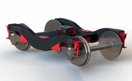
CARBON-FIBRE BOGIE FRAME
Centre Pivot / Traction Centre
Air-sprint Mount Secondary Lateral Bump Stop
Transom
Roll on eight months and your writer was attending the 16 th annual Vehicle/ Track System Interface Committee seminar where Professor Gerard
Fernando from the University of Birmingham presented his team’s work on a carbon-fibre bogie. Prof Fernando is Professor of Polymer Engineering and head of the sensors and composites group in the University’s School of Metallurgy and Materials. His collaborators included Dr Tom Sun and Mr Tao Ma.
This was no miniature bogie, but a full size one based on the design of the Alstom bogie used on the class 180
Side Frame
Radial Arm / Swing Arm Bush Bracket

Primary vertical damper bracket (including lift-stop and hard-stop) AntiRoll Bar Bracket Primary Vertical Damper
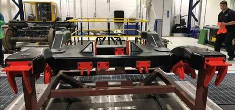
diesel-mechanical multiple unit. The aim of the project is to demonstrate a prototype that can withstand the rigours of 125mph operation with a life similar to a steel bogie and with much less mass. It is an RSSB-funded collaborative project involving ELG Carbon Fibre, Magma Structures, Alstom and the University of Birmingham. The ‘HAROLD’ full size test rig at the University of Huddersfield (issue 145) will be employed for testing.
The bogie frame - a typical H section - was designed and manufactured by Magma Structures in collaboration with the RSSB and other members of the
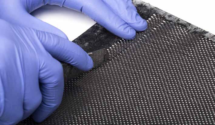
consortium. It was constructed out of new and recycled carbon fibres in a fire-retardant epoxy resin (supplied and developed by Gurit). The robotic build techniques used will also help to reduce mass manufacturing costs.
The design was constrained by the geometry of the existing class 180 bogie and, in order to manage the attachment and reuse of identical existing equipment, the primary brackets were fabricated in steel to interface exactly with the Alstom-supplied existing major components (radial arms, damper brackets, primary and secondary spring systems). The composite used in the construction has been tested to the requirements of the Euronorm for rolling stock fire safety, EN45545-2, at Hazard level 2 although, in fact, achieved a higher level 3. The former is the usual requirement for mainline operation.
A major achievement is that the mass of the frame as built is 350kg, compared to the steel equivalent of 936kg. By the time the metal fittings were installed and paint applied, the mass had increased to 940kg compared with the steel equivalent of 1468kg, a reduction of over half a tonne per bogie.
Gerard explained that the use of the metal components simplified the interfacing with the existing bogie

equipment and the carbody, but a bogie designed with carbon fibre construction in mind would be even lighter and would use much less steel.
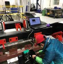
Optical fibres, sensors and sensing. Quite unexpectedly in a vehicle-track interface seminar, Gerard turned to the science of using optical fibres as strain and temperature gauges; these being the sensors used for testing the carbon fibre bogie, in addition to conventional surface-mounted electrical-resistance strain gauges.
RAIL DEPOT & WORKSHOP EQUIPMENT
• RAILCAR LIFTING JACKS • BOGIE/EQUIPMENT DROPS • TRAVERSERS • TURNTABLES • BOGIE WORKSHOP MACHINES • UNDER CAR EQUIPMENT HANDLING
• LASER MEASURING • SANDBOX FILLING • SHUNTERS • EXHAUST EXTRACTION • UNDER FLOOR WHEEL LATHES
mechan.co.uk info@mechan.co.uk +44 (0)114 257 0563

Davy Industrial Park Prince of Wales Road Sheffi eld S9 4EX
He explained how an optical fibre 125 micrometres in diameter (250 micrometres with a coating) can be used for this purpose. In very simple terms, a fibre is modified to create Fibre Bragg Gratings (FBG) in the fibre, effectively creating a number of semi-reflective mirrors over short but equal intervals – itself a highly technical process.
When light is shone through a Fibre Bragg Grating, part of the signal is reflected, a small amount of the signal at each semi-reflective mirror (see below). The original reflected wavelengths (without the influence of strain) from each Bragg grating are compared with the reflected wavelengths when the structure is loaded. If the Fibre Bragg Grating is subject to strain, the spacing between the semi-reflective mirrors is either slightly increased (tension) or reduced (compression). This change, combined with the effective refractive index and the period of the FBG, results in a shift in the reflected central Bragg wavelength.

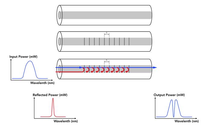
The size of the wavelength change indicates the magnitude of the strain. However, the same effect occurs with change of temperature and temperature effect is over 10 times the strain effect, so a method is required to correct for temperature.
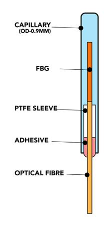
Gerard described the methods used to compensate for temperature where the Bragg grating is located close to the endface of a cleaved optical fibre. The fibre with the grating is housed in a capillary tube where one end is fused to the optical fibre, well away from the grating, and the opposite end is sealed (see right). Thus, the Bragg grating is primarily only responsive to temperature.
It is not just a matter of sticking a few strain gauges to the bogie and connecting them to the instrumentation either. The right optical fibre has to be selected; in this case bend-insensitive fibres from FiberCore UK. These are optical fibres where the diameter of the core consists of 9.5 micrometre fibres with 4.5 mm long Fibre Bragg Gratings.
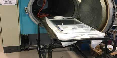
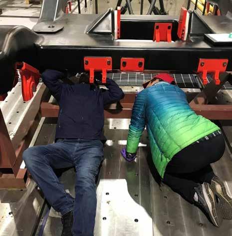
In addition, the Fibre Bragg Gratings have to be properly bonded to the bogie so as to behave as a homogeneous part of the structure. Gerard described the requirements for that bonding system, including efficient strain transfer, being able to accommodate localised variations in the surface topology of the composite, retaining the spatial orientation of the Fibre Bragg Gratings, being able to massproduce autoclaved sensor patches and
vacuum-bag bonding of the patches to the composite bogie. Several different bonding techniques and bonding agents were tried before the final choice. Further steps
The next stage is to carry out static and dynamic testing, including work on the University of Huddersfield’s HAROLD dynamic wheel-rail interface test rig. In parallel, the project team will be working with RSSB and others on appropriate standards that can be used to assess and authorise the bogie for on-track operation. Looking to the future, the original consortium, along with the NCC, are seeking further funding to build another two bogies that can be track tested on the rail to provide more real-life data and endorsement of the lightweight bogie,
including its use of composite recycled material, in the construction of rolling stock. Following this, given a clean design sheet, the consortium is confident that it can contribute to advancing a new-generation bogie which should demonstrate big cost and carbon savings by reducing rolling mass, incorporating more compliance in the structure (to substantially reduce track access charges) and using recycled materials.
With grateful thanks to Professor Gerard Fernando for his assistance in preparing this article.
Extend maintenance intervals with SKF Insight Rail For train operators, the main challenge is to keep trains running without costly interruptions. With SKF Insight Rail, a wireless and self-powered monitoring solution for passenger rail train bogies, you can now anticipate problems and extend maintenance intervals with confi dence.


Install on existing rolling stock in 2 minutes Measure close to the source for reliable results Notifi cations in your service organization’s dashboard or in the SKF app Find out more at skf.com/skfinsightrail


