
30 minute read
The day the railway became a canal
DAVID SHIRRES
Canals were a real problem for the early railway builders, as is illustrated by the steep gradients on the approaches to Euston and King’s Cross, where the railway was built respectively over and under the Regent’s Canal. The Midland Railway avoided this problem by building an elevated station at St Pancras.
In Scotland, the Monklands canal forced the Edinburgh to Glasgow railway to build a tunnel with a 1 in 41 gradient to reach its Glasgow Queen Street terminus whilst various bridges and tunnels were needed to cross the Forth and Clyde canal which cut across central Scotland.
It could have been worse if Robert Stephenson, of lighthouse fame, had had his way. In 1817, Stephenson proposed a level canal between Glasgow and Edinburgh. This was to have a basin where Edinburgh Waverley station is now, following the line of what was to be the railway through Princess Street gardens to Haymarket and then continuing along the 155-foot contour to join the Forth and Clyde canal at its summit pound, seven miles west of Falkirk, which extends to Port Dundas in Glasgow.
A canal without any locks between Scotland’s two main cities was a commercially attractive proposition for both passengers and freight. However, there was a snag – it required the construction of a three-mile-long two-way canal tunnel at Winchburgh. The costs and risks of such a tunnel were too much for the canal’s promoters, who chose Hugh Baird’s line to build the Edinburgh and Glasgow Union Canal, which opened in 1822. A swift passenger boat was then introduced that took eight hours between the two cities and carried 200,000 passengers a year.
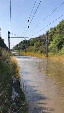
The Union Canal is a level canal that follows the 240-foot contour from Fountainbridge in Edinburgh to Falkirk. There, it joined the Forth and Clyde canal by a flight of 11 locks, which were demolished in the 1930s. The Millennium Link restored these two canals and, in 2002, re-joined them by the Falkirk Wheel, which is Scotland’s 15th most visited tourist attraction.
When the Edinburgh and Glasgow Railway opened in 1842, it took away all of the canal’s passenger traffic and much of its freight traffic. Eventually, in 1849, the railway took over the whole Union Canal. Evidence of this common


ownership can by seen at the Linlithgow Union Canal Society’s basin, where the railway’s original stone block sleepers line the quayside.
As railways were built, the canal companies were gradually put out of business and, for many years, there has been little interaction between canals and the railway. However, in August 2020, there was a significant exception.
12 August
In the early morning of 12 August, eastern Scotland experienced exceptionally severe storms that tragically resulted in the fatal train crash at Carmont, where 52mm of rain had fallen between 05:00 and 09:00. Further south, near Polmont, 80mm of rain fell between midnight and 06:00, with 44mm falling in one hour around 05:00. The Scottish Environmental Protection Agency subsequently considered this to be a 1-in-240-year event, although, during the night of the storm there was only a Yellow warning in place.
At 05:46, multiple track circuit failures on the Edinburgh to Glasgow main line between Polmont and Bo’ness junction were reported to Network Rail Scotland control. The driver of 2J53, the 05:03 from Edinburgh to Glasgow, reported that water was above the rail head on both lines at this location and was flowing fast. 2J53 was the first, and the last, train over the line that day.
Scottish Canals received a report that the Union Canal had been breached at Muiravonside, between Linlithgow and Polmont, at 08:00. The breach was initially a few metres across, eventually growing to a 30-metre gap in the six-metre-high canal embankment, through which a vast amount of water was flowing.
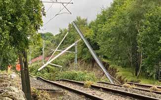
At 08:52, the Cathcart Electrical Control reported an overhead line trip in the area as overhead line structures collapsed after their foundations were washed away.

By 11:00, Scottish Canals had put stop planks under bridges at Brightons, near Polmont, and Linlithgow. This restricted the loss of water to six kilometres of the 51-kilometre level canal. By this time, the level of the canal at Linlithgow, 4.6 kilometres from the breach, had dropped by half a metre.
Later that afternoon, Scottish Canals contractors Mackenzie Construction installed emergency sandbag dams under bridges either side of the canal to contain the leaking section to one kilometre, which significantly reduced the water flow through the breach. By this time, tens of thousands of cubic metres of water had poured onto the adjacent railway line.
The next day, clay dams were installed 100 metres either side of the breach to completely stop the water flow through it. As the canal is fed only from its eastern end, a pumping system was provided at the east end of the breach to pump water to the west side of the breach through pipes that bypassed the drained section of the canal. A week-long fish rescue exercise was then undertaken to move over eleven thousand trapped fish, including a one-metre-long 30-year old eel, to unaffected sections of the canal. Clay dam and pumps 150 metres east of the breach.
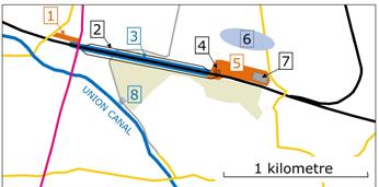
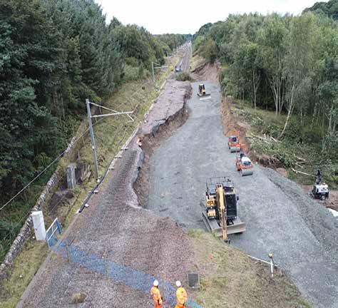
(Above) Cutting suffered little damage where canal water poured into it. (Inset) 1. Worksite No 3 - QTS. 2. Cutting. 3. Worksite No 2 - Track Alliance. 4. Major embankment failure. 5. Worksite No 1 - QTS. 6. Main flooding after canal breach. 7. Site compound. 8. Canal breach.
Canal Asset Management
Scottish Canals manage the Caledonian, Crinan, Forth & Clyde, Monkland and Union canals, which total 140 miles of waterway. Its 2018/19 accounts show that £9.1 million (£65,000 per mile) was spent on major infrastructure and core waterway works, and note that its historic assets have been in a steady state of decline, with the risk of asset failure ever present. Unlike Scotland’s canals, it would be wrong to describe railway earthworks as being in decline as Network Rail’s investment in them has doubled in the past ten years to £1.3 billion in Control Period 6 (2019-2024). However, canal and railway assets are both at risk from severe weather events.
To address this risk, the Scottish Canals’ asset management strategy shows how work on their 4,100 assets is prioritised through a risk assessment process. This had identified that 175 assets presented a ‘high’ or ‘severe’ risk of failure.
Scottish Canals director of infrastructure Richard Millar told Rail Engineer that these high/severe risk assets did not include the failed embankment at Muiravonside. He noted that this 200-metre long embankment was a “substantial, chunky” earthwork with much clay in its cross section. It had received a principle examination by a qualified engineer in 2018. Such examinations are undertaken every three to ten years according to risk. Each part of the canal also receives a monthly inspection and an annual detailed inspection.
The 51-kilometre Union canal has 13 ‘waste’ weirs along its length to regulate the level of water in it. Richard advised that, during the storm, significant flows were generated in the upstream catchment resulting in large uncontrolled flows into the canal which had overwhelmed these weirs resulting in the canal overtopping at several locations. At Muiravonside, this eroded the embankment to create a 30-metre wide breach. He considers the repair of this breach repair is a big job that will take some months.
Following the Muiravonside breach, Scottish Canals are considering how canals can be made more resilient to such severe weather events. Richard advised that Scottish Canals are working closely with Network Rail in respect of the railway flood repair work and envisages that the two infrastructure companies will share their strategies to improve the resilience of their 19th century infrastructure.
He also pointed out that canals can also be part of the solution for severe weather events as they can accommodate and move large volumes of water. As an example, he mentions the ‘Glasgow Smart Canal’ scheme that has paved the way for 3,000 new homes in Glasgow by contributing to a wider scheme to mitigate flood risk. This will be done by actively and autonomously lowering the water level in the Forth & Clyde canal by up to 10cm to accommodate 55,000 cubic metres of floodwater when severe weather is predicted.
Après le déluge
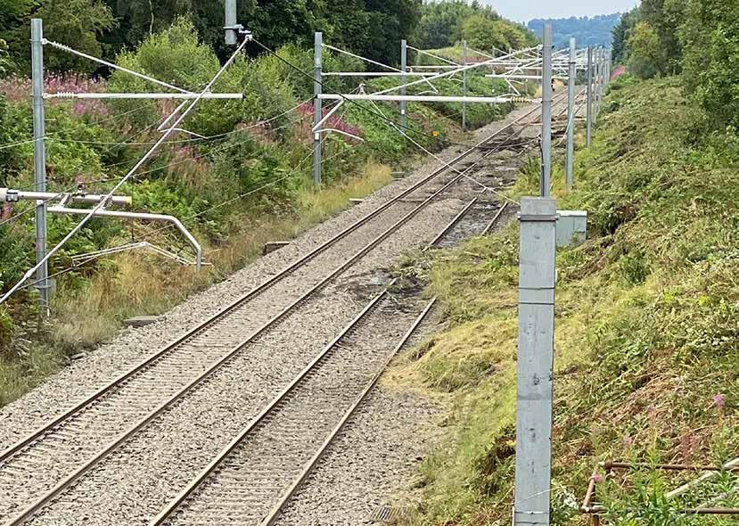
As the fast-flowing water escaped from the canal, it flowed down through a wood for 300 metres before pouring over the south side of a one-kilometre long shallow cutting on the Edinburgh to Glasgow main line. Little One of two OLE damage was done at masts that had foundations washed away.this point as the wood had spread the flow.
At this point the line is on a very slight, 1 in 882 gradient that falls eastwards towards Edinburgh. The flood water covered the rails in the cutting and poured out of both ends of it with most flowing out of the east end of the cutting. It was here that most of the damage was done as the water poured down a 10-metre high embankment on the north side of the line to flood the fields below. The scour of tens of thousands of tonnes of water changing and speeding up dug out OLE mast foundations and about 150 metres of trackbed, leaving sagging, unsupported track in a scene reminiscent of Dawlish in 2014.
Network Rail’s project manager for the flood repair works, Mark Wilson, advised that it took three days for the water to filter through the site before a full damage assessment could be made. This found that there was: » One kilometre of contaminated ballast; » 1.3 kilometres of track formation to renew; » Two embankment failures, one of which was up to nine metres deep, and significant soil cutting failures; » 3.5 kilometres of signalling cable requiring renewal and location cases damaged from water ingress; » Two collapsed OLE masts with associated wiring damage; » 8,000 to 10,000 tonnes of track formation debris from the main failure site that had been deposited on non-arable third-party land. A decision on whether this has to be moved has yet to be taken.
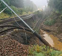
Aerial view shows scour under both tracks where flood water left the cutting.
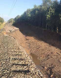
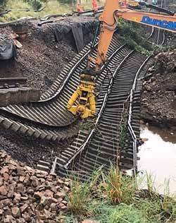
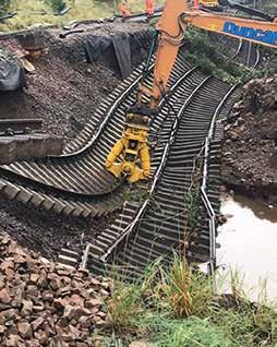
Infilling main embankment failure. Design
Network Rail’s geotechnical framework contractor QTS, supported by COWI, which provides geotechnical engineering services, was immediately mobilised to establish a site compound below the main embankment failure. For Mark, the urgent timeframe to prepare the design was particularly challenging. He advised that the geotechnical design was derived from designer’s sketches from which retrospective Form 001 and 002s were produced, as allowed by the civil engineering assurance standard. Geotechnical designers were also on site throughout to supervise the works.
The design for the new formation at the main embankment failure area required an infill of between 1.5 and nine metres, which consisted of a compacted primary fill layer of 6B (100-300mm) stone followed by incremental layers (130mm to 150mm thick) of compacted 6F5 stone to reach final formation level. In all, approximately 9,500 tonnes of stone would be needed.
The Rail Systems Alliance Scotland, a threeway joint venture of Network Rail, Babcock Rail and Arcadis, designed the track renewal, signal and telecoms remediation works as well as the soil cutting damage repair within the track renewals worksite. It was agreed with the route asset manager that a category 11 track renewal (rerail, resleeper and reballast) was required. A combined form A/B for track design was produced, reviewed and accepted to allow approved for construction drawings to be issued six hours before work started.
The scope of the signalling and telecoms work was informed by advice from the local maintenance team. The S&T cables were located in two separate troughing routes, one in the cess and one at the crest of the soil cutting. To improve maintainability and increase resilience it was decided to rationalise this by cutting and relocating the cables into one cable trough within the cess with new location cabinets installed at appropriate locations.
This required several signalling cables to be cut and 3,000 metres of new cables to be run in. One saving was that it was found that the fibre optic telecoms cable, installed during the Edinburgh to Glasgow improvement programme (EGIP), could be reused.
The remedial overhead line equipment work was designed by SPL Powerlines and was aided by the use of EGIP records for the design of foundations for the two new twin track cantilever overhead line structures on the south side of the track. These replaced single track OLE masts at the two locations where masts on the north side of the track had had their foundations washed away.
It was considered that twin track OLE gantries were a more robust and ‘future proof’ solution in accordance with what Mark described as “Scotland’s railway ethos of building back better”. This decision also aided the programme, as it meant that the mast’s foundations were away from the embankment remedial work.
Delivery
Mark considers that the most significant challenges in delivering these remedial works were compliance with the Construction, Design and Management Regulations (with three different contractors on site), finalising remits from the various asset managers with very short timescales, liaison with the many parties involved and engineering train planning. Furthermore, having initially estimated six and a half weeks to complete the work, his team were challenged to achieve five and a half weeks. He advised that the project planning needed to achieve this was quite demanding.
The CDM issues were resolved by having three distinct sites of work. QTS was the principal contractor for the embankment remediation sites at each end of the cutting. Between these two sites, the Rail Systems Alliance Scotland was the principal contractor for the track renewals site. Other contractors on site included Story Contracting, which provided rail plant, and SPL Powerlines for the installation of the twin track cantilever masts and OLE repairs.
Although Scottish Canals contractors have their own compounds and separate access arrangements, there was a requirement for some common site access, for example visits of the loss adjusters. There are also ongoing discussions with Scottish Canals regarding the mitigation of any repeat occurrence, especially as the canal lies above and close to the railway for several kilometres.
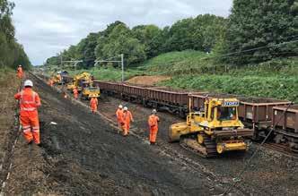
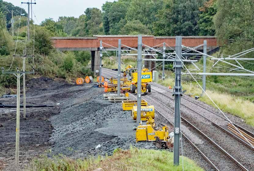
Achieving the formation level in time for track renewal works was very much on the critical path and did happen just in time. Once the embankment works were complete, the three worksites were merged into one track renewals site.
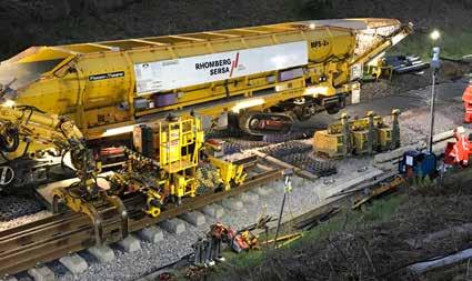
The 27 engineering trains for the track renewals work were also on the critical path and required the replanning of train moves and engineering work across the network. One such train was that with Rhomberg Sersa’s MFS+ (material conveyor and hopper unit with transfer conveyor belt and caterpillar track) which was sent to Polmont from its deployment on Scotland’s Far North line. As reported in issue 180 (December 2019), the MFS+ is a highoutput conveyor/hopper wagon that can lift itself clear of the running line and then wander off into an excavation. At Polmont, it was used to deposit ballast away from the railhead. (Above) Work is almost complete at the minor embankment remediation worksite at the western end of the cutting.
(Inset) Rhomberg Sersa’s MFS delivering ballast at the railhead.
(Left) Preparing Down line trackbed, photograph shows the abandoned crest troughing route.
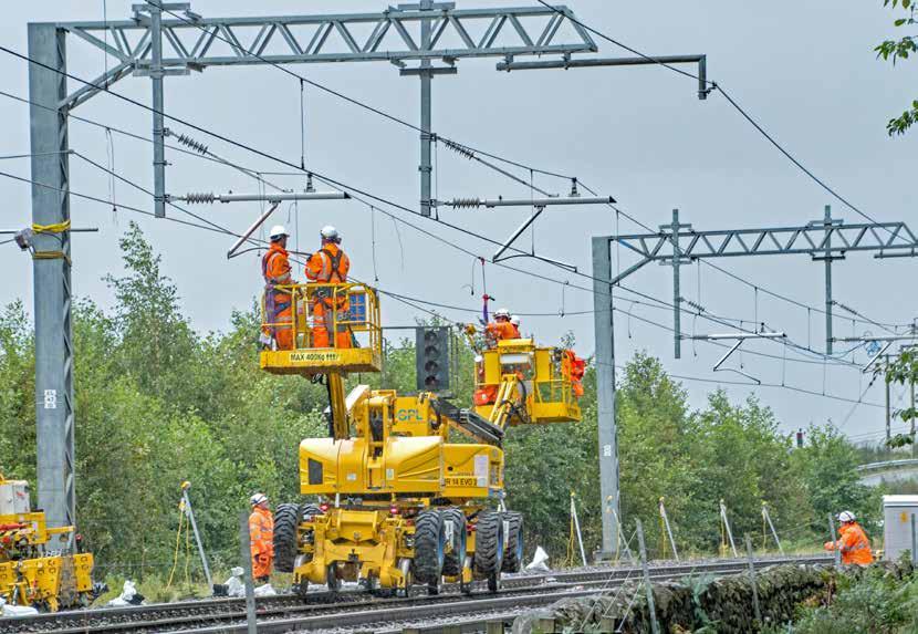
(Above) SPL Powerlines installing contact wire on the Up line. (Inset) Work complete - photograph shows the two new twin-track cantilever OLE masts, new cess troughing route and cutting repair.
At the track renewal site, the contaminated ballast was excavated out and existing formation level was cleaned. 10,000 tonnes of new ballast was laid on a geotextile layer on top of the cleaned new formation.
The existing rails were not re-used as they had to be cut into panels to enable efficient removal from site. New rails were run in by engineering trains and laid in the four-foot of the opposite line. The Down line renewal was completed first, followed by the Up line. Work then transferred to the embankment failure site where both lines were renewed once formation level was achieved. The track renewal required 4,500 metres of new rails and 4,424 concrete sleepers.
During the flood repair works, there were no passenger trains between Falkirk and Linlithgow. Whilst the line was closed, other work was carried out to take advantage of this possession, including signalling upgrade works at Falkirk High tunnel, devegetation through the Polmont area and other minor earthwork repairs elsewhere following the storm on 12 August.
After all work had been completed, all the relevant handback paperwork was gathered to show that the new and repaired assets are “suitable, sufficient and correctly configured to provide for the safe functional operational requirements of the railway infrastructure” as required by Network Rail’s ‘Entry into operational service’ standard.
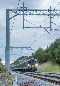
Once this was done, services on the main Edinburgh to Glasgow route resumed on 21 September with a temporary 60mph speed restriction, 40 days after the line’s inundation by the Union Canal. Commenting on the work, Michael Matheson, the Scottish Government’s Cabinet Secretary for Transport, Infrastructure and Connectivity, stated “The scale of the challenge faced by those repairing the damage to this vital route was huge and that they have delivered this so promptly is testament to the hard work and dedication of staff across Scotland’s Railway.”
It’s hard to disagree with him.

Digitally enabled modular bridges

MUNGO STACY
Build, build, build! – heartening words for construction. Better, greener, faster – the imperatives for the industry. But what remains unspoken is the poor past-performance of the sector. Since the mid-1990s, the productivity of manufacturing has improved by 50 per cent. In the same period, construction productivity has remained unchanged.
The uptake of manufacturing-style techniques, so-called ‘modern methods of construction’, is being promoted as a means of closing the productivity gap. These methods include off-site manufacture.
The use of transporters to ‘drive in’ prefabricated bridge decks is widespread in the rail industry, to permit construction within short possession constraints. But can similar techniques be adopted for the substructures?
In a 12-month, £1 million development project, Laing O’Rourke, supported by WSP and Ramboll, created a set of pre-approved modular bridge products to enable more off-site manufactured components to be used in the delivery of bridges. The project is a result of the competition that Highways England launched in February 2019, alongside Innovate UK, to encourage new ideas aimed at revolutionising roads and driving. HS2 enabling works contractor LMJV (Laing O’Rourke and J Murphy & Sons Joint Venture) used these products in the construction of the M42 bridge installed over the weekend of 8-9 August 2020.
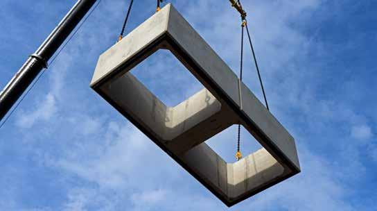
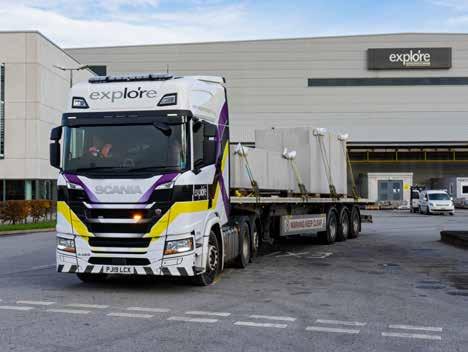
Precast modular abutment shells leaving Laing O'Rourke's state-of-the-art factory in Nottinghamshire.
Off-site advantage
Phil Robinson, civil engineering leader at Laing O’Rourke’s Dartford headquarters, commented: “Off-site manufacturing is at the heart of Laing O’Rourke’s business. Over a decade ago, we invested in a state-of-the-art precast factory in Nottinghamshire, and it remains the most automated concrete production facility in Europe. We have a target of 70 per cent of the construction being conducted off-site, leading to a 60 per cent improvement in productivity, and a 30 per cent improvement in delivery schedule.
“We have been recognised for many years for our modular products in the buildings sector,” Phil continued. “The Highways England funding offered a perfect opportunity for us to accelerate our efforts to grow our product range and achieve a step-change in the delivery of bridges.”
An obvious key benefit of using off-site products is faster construction, saving indirect costs and reducing disruption to
The precast unit forms voids for in-situ concrete.
the transport network. But there are other inherent benefits to using off-site modular products.
The repetition of assembling standard units, with site teams familiar with working with the components, reduces construction risk compared to one-off solutions. The transfer of labour hours from site into the controlled conditions of the factory improves well-being, with better environmental and ergonomic working arrangements. Also, safety is designed into the system, with reduced work at height.
Modular abutments
Recognising that standardised precast deck beams have been used for decades, the focus of this work has been a modular system for abutments, wing-walls and piers. It is based on precast shell units that are two metres high, 1.75 metres deep and form a two-metre horizontal grid. The units can be stacked to create the required height of abutment or wall, with matching sloping L-wall units to form wing-walls.
A challenge for off-site construction is forming the connections between prefabricated units, particularly given the high forces present in bridges. The shell system provides a relatively thin precast wall around internal voids, and delivers a high-quality factory-formed finish. The structural strength is provided by in-situ concrete poured within the voids.
The current system is an evolution, already on its third iteration. Phil Robinson explained: “We used off-site techniques on the A453 road widening scheme back in 2013. Then came the Staffordshire Rail Alliance. Now we are applying the system on the East West Rail and HS2 projects. With each deployment, we have been using the lessons learned to refine the system.”
A key engineering choice is whether to make the precast unit participate structurally. Earlier iterations included this composite behaviour, making the section structurally efficient but requiring reinforcement across the interface and more complex assembly. The current shell solution treats the precast unit as non-participatory formwork. The overall volume of concrete is therefore higher than for a comparable in-situ solution, but all the benefits of rapid installation are gained. In addition, since early strength gain is no longer needed to strip the formwork, then a lower cement content can be used, giving a lower carbon content. The approved installer scheme defines requirements to ensure critical tolerances are met. Design for Manufacture and Assembly
With off-site manufacture, the details Pre-assured system Configuration tool of installation need to be carefully The full title of the innovation project is The second aspect of the project was to thought through at the design stage ‘digitally enabled and assured product- develop a digital configuration tool. Enter since ‘technical adjustments’ are not based bridges’. The title captures two the parameters of the bridge – span, possible on site. The units are designed key aspects – the pre-assurance through skew, height, width – and the tool outputs for manufacture, with lifting points cast certification of the product set, and the set of products needed to build the in and the potential product variations the digital enabling through an online bridge. With the aim of streamlining accommodated within the limitations of configuration tool. concept design, the tool also outputs a the moulds. Certification is being progressed 3D model in IFC format, the Approval
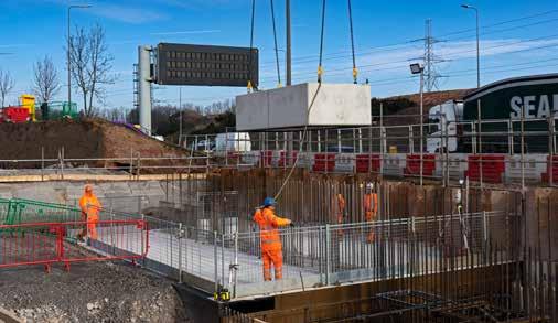
The shell units are installed over starter through BBA (British Board of Agrément), in Principle document and provides the bars projecting from the pilecap. Setting the UK construction certification body. cost. The tool enables the modular design out of the starter bars is absolutely Certification has defined performance option to be considered alongside other critical, otherwise the shells will not fit. characteristics of the products that can be forms of construction, but the detailed Guide frames were developed to align relied upon, for example, the suitability design of the bridge is still carried out by the starter bars and maintain the relative of the shells to withstand the internal the project designer. positions. pressure applied from an eight-metre The value of the tool is in configuring
Likewise, the lap between the starter head of concrete when filling the void. It the arrangement of products, including bars and the down-hole cage is designed is supported by a manufacturing quality the variable features, to suit the site as a non-contact lap, to provide tolerance plan, with ongoing monitoring by BBA requirements. The concept of ‘mass as the cage is slid down the void. Getting to ensure the requirements of the quality customisation’ captures the adaptation, such details right allows the system to plan are fulfilled. In addition, an approved within defined limits, of a set of standard be repeated successfully across multiple installer scheme defines requirements for products to a particular need. For structures. installation. example, variation in abutment height is obtained using a stop-end in the The precast shell units allow rapid installation of abutments adjacent to live traffic. mould to adjust the height of the lowest, below-ground, unit. Similarly, variations in the height of the uppermost units can be used to follow the crossfall of a bridge. The tool covers typical cases for singlespan integral bridges using industrystandard prestressed concrete beams, but also introducing the abutment shells and other modular bridge products. It covers spans of between 15 and 40 metres, using Y and W beams. Skew can range from 0 to 30 degrees, corresponding to the application of the standard limit equilibrium approaches for integral bridge design. Abutment heights of four to ten metres cover typical clearance envelopes for highway and rail schemes including, at the low end, river crossings.

Parametric analysis
John Armitage, technical director at Ramboll, said: “Analysis of integral bridges is complex, because all the effects are interdependent - the behaviour of the deck, the abutments and the ground. We have pre-engineered the products by running a parametric analysis covering the range of different geometries. The benefit of using this tool is that it provides confidence to a user that a valid solution can be developed, short-cutting an analysis that would normally take up to two weeks to perform at preliminary design stage.”
The configuration tool works with a lookup table based on the results of numerous analysis runs. A pair of sophisticated parametric models were developed by WSP and Ramboll, with design automation allowing set-up of model geometry, analysis, and results extraction to occur without manual input. Independence of the models allowed cross-checking of results between the two design organisations to guard against error.
Gbenga Oludotun, project manager for WSP, added: “The project was delivered during lockdown, but we were still able to make use of the desktop computers locked in offices. We used virtual remote access and ran batches of analysis on half a dozen machines in parallel. Ultimately, we set up to run 1,500 different bridge configurations and generated the results over a weekend.”
Application to HS2
The modular bridge products have been used to speed up the installation of four of the first bridges to be built for HS2. Laing O’Rourke, in joint venture with J Murphy & Sons as LMJV, are the contractors for the Enabling Works
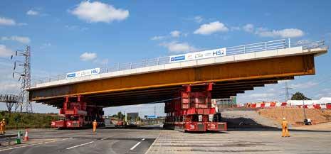
The 2,750 tonne superstructure was installed over the M42, with the motorway reopening 22 hours early.
North. The four bridges are part of major highway improvements around the future HS2 Interchange Station in Solihull, which will be the heart of the new high-speed railway.
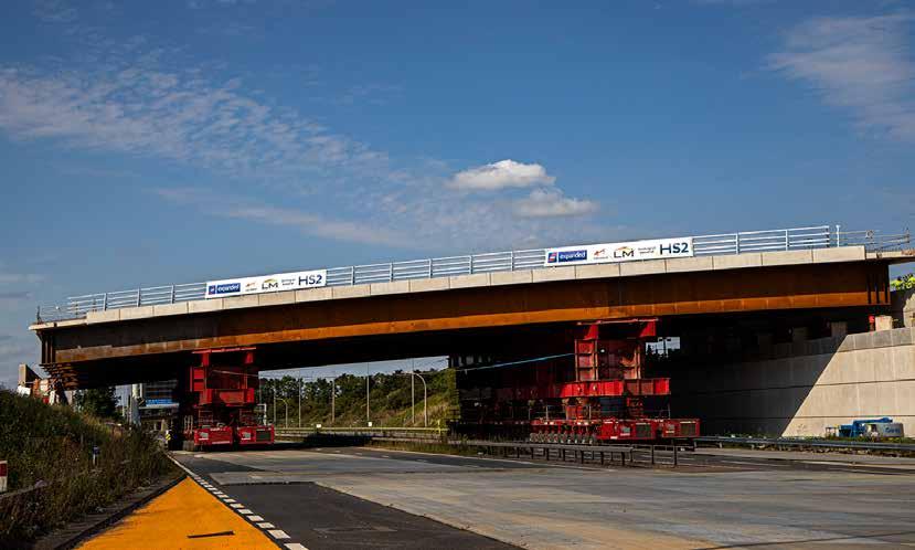
The largest bridge, with a 65-metre span, was installed over the M42 motorway over the weekend of 8-9 August 2020. The deck, weighing 2,750 tonnes, was constructed alongside the motorway and manoeuvred into place on self-propelled modular transporters. Thanks to an immaculately planned operation, the motorway was reopened to traffic a full 22 hours early. This success illustrates the flexibility of the modular bridge system, where the same abutment shells were used with a steel-concrete composite deck supported on bearings.
Future development
Next steps for the project team include extending the cases covered by the product certification and configuration tool. Additions could include steel beams to supplement the prestressed concrete beams, extension to multi-span bridges using the shells to form central piers, and including other products, such as precast deck panels and a range of parapet stringcourse beams. The team continues to use each deployment to improve the system and products for the benefits of the design, construction and maintenance of bridges.
The system is attracting interest from many clients and sectors, with use demonstrated on these HS2 bridges, applications well advanced on East West Rail, and the innovation funding support from Highways England.
Paul Doney, director of innovation and continuous improvement, said: “At Highways England, we are committed to support innovations that enable better ways of working, particularly if they are safer for our workforce and reduce disruption for road users. Projects such as this support our ambitions for digital design and construction that will benefit the whole construction industry, and we're already seeing benefits with less disruption drivers.”
The adoption of digital technologies to allow configuration and customisation of the standard units offers the flexibility to adapt the use of the products to each particular site arrangement, whilst realising the benefits of quality and efficiency through the application of a manufacturing approach to construction – exactly as required to build better, greener, faster.
Mungo Stacy is head of profession, civil bridge and ground, at WSP.
Modular passenger lifts FOR TEMPORARY ACCESS
Across the country, simple footbridges at stations, which cross the tracks from one platform to another, are being replaced as part of the ‘Access for All’ scheme. Typically, the new bridges have a passenger lift for each platform, so that the disabled, passengers with heavy luggage, families with prams and pushchairs and anyone else with mobility difficulties can access all of the platforms and the trains.
However, when a temporary footbridge is needed, this can be a problem. Traditional styles made from scaffolding don’t have lifts, so those with mobility problems can be disadvantaged.
When Deutsche Bahn had this problem in Germany, it turned to RECO Lift Solutions, which supplied three type PP passenger lifts for a temporary pedestrian bridge crossing the tracks in Berlin.
PP stands for Plug & Play, which means that the lift shaft can be installed with just one crane lift and is then ready to be used. All that is needed is a foundation and a power supply, then the temporary RECO passenger lifts provide a step-free and safe access for railway passengers using the temporary passenger bridge.
Safe and step-free
Based in the Netherlands, RECO Lift Solutions specialises in renting out temporary passenger lifts all over Europe.
“In the international infrastructure market, we work a lot for the railway companies,” explained Jakob Ebbens, RECO’s international accounts manager. “All over Europe, we see a trend that customeroriented railway companies want to maintain full step-free track access for their passengers in all circumstances.
“This is also the case for temporary structures like temporary pedestrian bridges. Due to overhead line equipment, these temporary pedestrian bridges need a minimum height of 7.5 to 8 metres. For passengers with prams, bikes or disabled people in wheelchairs, the stairs leading up to such a bridge are an impregnable barrier.
“With the use of a temporary RECO passenger lift, we offer railway passengers the comfort of a passenger lift with an enclosed lift shaft.”
Railway station Berlin Schöneweide
Having been part of the Deutsche Bahn network for more than 100 years, Berlin Schöneweide railway station no longer meets contemporary standards. As a consequence, DB is modernising the station to make it more appealing and comfortable for passengers.

The station features a passenger tunnel with lifts for those that need them. As these lifts would be out of service throughout the modernisation works, Deutsche Bahn decided to install a temporary footbridge, courtesy of engineering contractor Spitzke, which has its eastern regional headquarters at Großbeeren, just south of Berlin.
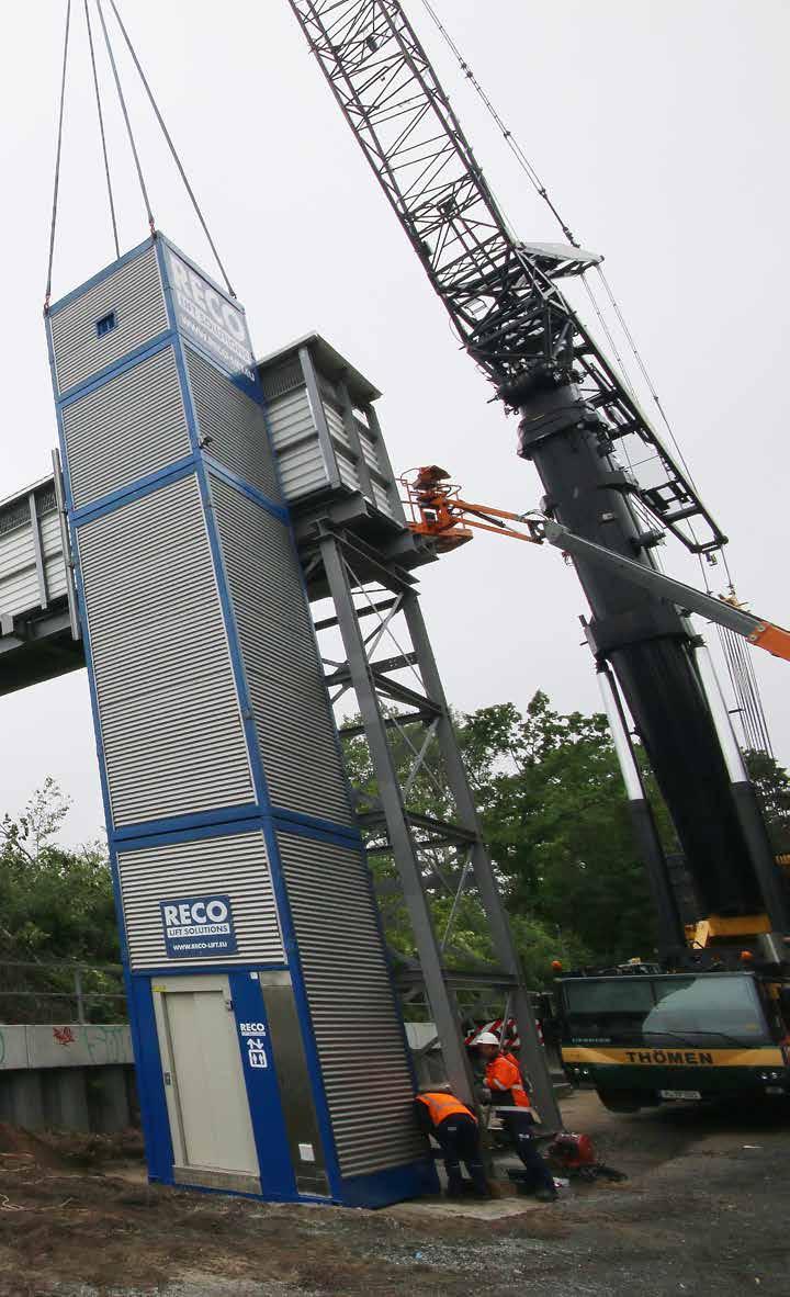
Spitzke cast concrete foundations for three temporary lift shafts. Directly after lifting in the temporary footbridge, a 500-tonne crane, on hire from another Berlin company, Thömen, lifted in the three temporary RECO PP passenger lifts. The lift shafts were anchored to the concrete foundation using Hilti chemical-glue anchors.
RECO temporary lift shafts that are under 12 metres high can be free standing, However, one of these three was 14.6 metres high, so it needed to be tied into the bridge structure for added stability.
“Using temporary RECO type PP passenger lifts, all customers will be able to use the temporary footbridge,” said Mr. Springer from infrastructure owner DB Netz. “In only 24 hours, RECO installed three temporary passenger lifts without disturbing train traffic. The temporary lifts use the same lift technology and operation as our existing lifts at the railway station, adding to the comfort and user friendliness for our users.”
“Engineering firms and specification writers that operate in Germany’s infrastructure sector are increasingly seeking us out for temporary lift solutions,” commented Jakob Ebbens. “To make travelling by train more appealing, railway operators are not only improving rolling stock and timetables, but stations as well.”
Research has shown that the station experience contributes a hefty 25 per cent towards overall passenger satisfaction. Given that safe and step-free access to trains is a basic passenger need, its influence on passenger satisfaction is considerable.
Modular set up
RECO’s PP passenger lifts are modular in concept. Jakob Ebbens explained: “Depending on the needs of our clients in number of stops or travel height for the cabin, we can simply adjust the height of the lift shaft. For this project, for example, we have installed two nine-metrehigh lift shafts and one at 14.6 metres.

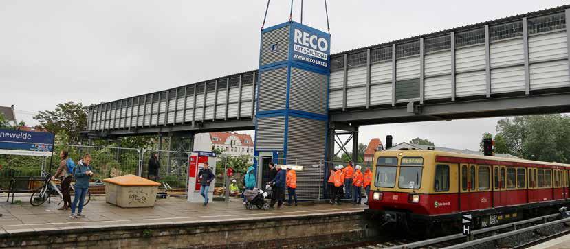
“We also have flexibility in the cabin configuration. For this project, Deutsche Bahn preferred a walk-through cabin for a better traffic flow.”
RECO is using standard lift technology for its passenger lifts. “Since we work all over Europe, and our engineers are based in the Netherlands, we always want to make sure that a local elevator service company is familiar with the lift technology that we are using. This enables us to provide prompt customer service in case there is a technical problem,” Jakob Ebbens stated.
For the project in Berlin, elevator service company Schmitt & Sohn is both assisting RECO with technical support and taking care of maintenance.
With safety being paramount, all RECO temporary passenger lifts are commissioned by a local notified body before use. In the UK, Bureau Veritas UK is undertaking this service.
All of the lift cabins are fitted with an emergency call button in the lift cabin. While RECO offers clients use of its emergency call system, station owners and operators often want to build in their own, which are fully compatible with the systems they are already using.
In the UK, RECO has supplied projects such as Crossrail, Docklands Light Railway and Manchester Airport, and is working on several projects for Network Rail. When needed, additional support can be provided by sister company RECO Hoist Ltd of St Ives, Cambridgeshire.


