DRAWN BY: CHECKED BY: SHEET NUMBER DATE: URBANbuild14 1920 HARMONY STREET, NEW ORLEANS, LOUISIANA 70115 SHEET NAME PROJECT PHASE TULANE UNIVERSITY TULANE SCHOOL OF ARCHITECTURE B. MOUTON CONSTRUCTION DOCUMENTS 5.2 BUILDING SECTION R. DUPLANTIER NO: ISSUED FOR: DATE: 5.2 2.1 3/8" = 1'-0" LONGITUDINAL SECTION B 1 + STAIR DETAILS 5.2 2.1 3/4" = 1'-0" DETAIL - STAIR PLAN 2 5.2 2.1 3/4" = 1'-0" DETAIL - STAIR ELEVATION 3 ReneDuplantier architectural portfolio 2023
It’s over there. It’s over there. My building has every convenience. It’s gonna make life easy for me. It’s gonna be easy to get things done. I will relax along with my loved ones.
Loved ones, loved ones visit the building, take the highway, park, and come up and see me. I’ll be working, working, but if you come visit, I’ll put down what I’m doing. My friends are important.
3401 St. Charles Hotel Saint Vincent Affordable Smiles 100 Oriole Alexander’s Market
Kim and Don’s House Hostel Apartment mixed media map projection
URBANbuild14
W(ork).1 W.2 W.3 W.4 W.5 P(ersonal).1 S(chool).1 S.2 S.3 S.4
Talking Heads “Don’t Worry About the Government” 1977
Contents:
block elevations


W.1 3401 St. Charles right of way plan detail
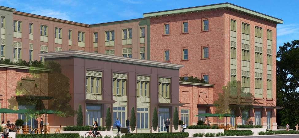
W.1 3401 St. Charles - New Orleans, LA
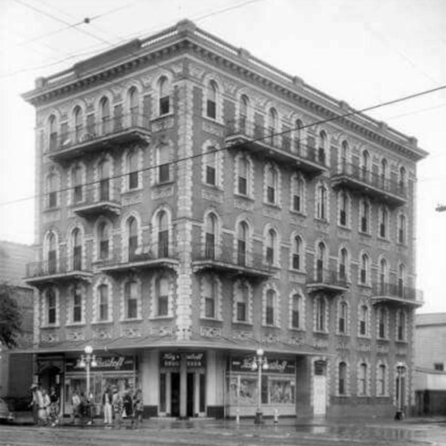
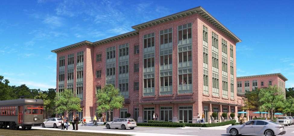
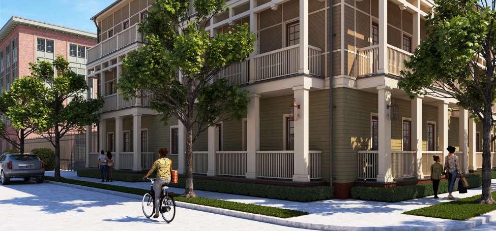
Since 2005, New Orleans as a whole has made great steps to replace parking lots and former industrial areas with housing. I’ve been extremely fortunate to contribute to that effort on the design team for 3401 St. Charles, a mixed-use development on the corner of St. Charles Avenue and Louisiana Avenue. This site was once home to a seven story apartment building with the ground floor housing a Katz and Besthoff drugstore. The Besthoff family retains ownership of the property and hired MetroStudio to restore this historic use. The project occupies almost an entire city block. It consists of 20,000 sf of retail space; 114 one, two, and three bedroom market rate rental units (in two buildings); 140 parking spaces; and major improvements to the surrounding right-of-ways. During the design process, our team has collaborated with local design regulatory agencies, the department of parks and parkways, the department of housing and urban development, neighborhood groups, and the board of zoning adjustments in addition to regular collaboration with consultants. Construction is set to begin in 2023.
PL PL PL PL PL PL PL PL #DrgID #LayID ST CHARLES AVE LOUISIANA AVE DELACHAISE ST CARONDELET ST PL B501 SLOPE 1 4 12 SLOPE 4 12 SLOPE 1 4 12 SLOPE 1/4 12 SLOPE 1 4:12 SLOPE 1/4 12 SLOPE 1 4 12 SLOPE 1 4 12 SLOPE 1/4 12 SLOPE 6 12 SLOPE 6 12 SLOPE 6 12 SLOPE 6 12 SCALE 1 16" 1 -0 1 SITE PLAN 0 8 16 32 B A C site plan historic condition
LOUISIANA AVE | SOUTH ST LOUISIANA AVE | NORTH LOUISIANA AVE | ST CHARLES D E F G ARC-301 REVISION ISSUE # SHEET TITLE THESE DOCUMENTS HAVE BEEN PREPARED BY UNDER MY CLOSE PERSONAL SUPERVISION AND COMPLY WITH ALL CITY REQUIREMENTS SEAL DATE CONSULTANTS MECHANICAL ELECTRICAL PLUMBING ENGINEER THOMPSON LUKE AND ASSOCIATES 3071 TEDDY DRIVE BATON ROUGE LA 70809 225 293 9474 ARC REVIEW 1 10 NOT FOR CONSTRUCTION CIVIL STRUCTURAL ENGINEER FOX-NESBIT ENGINEERING LLC 1515 POYDRAS STREET SUITE 1020 NEW ORLEANS LA 70112 504 500 9640 LANDSCAPE DESIGNER SPACKMAN MOSSOP MICHAELS 1824 SOPHIE WRIGHT PLACE NEW ORLEANS LA 504 218 8991 ARC REVIEW 2 1 LA | StC Development Louisiana Avenue St Charles New Orleans LA 70115 3-D RENDERINGS 6501 Spanish Fort Blvd New Orleans LA 504 283 3685 // etrostudio net CARONDELET | DELACHAISE DELACHAISE A B SHEET TITLE THESE DOCUMENTS HAVE BEEN PREPARED BY ME OR CLOSE PERSONAL SUPERVISION REQUIREMENTS SEAL CONSULTANTS THOMPSON LUKE AND ASSOCIATES LLC 3071 TEDDY DRIVE BATON ROUGE LA 70809 225 293 9474 ARC REVIEW 10 07 202 NOT FOR CONSTRUCTION FOX-NESBIT ENGINEERING LLC 1515 POYDRAS STREET SUITE 1020 NEW ORLEANS LA 70112 504 500 9640 SPACKMAN MOSSOP MICHAELS 1824 SOPHIE WRIGHT PLACE NEW ORLEANS LA 504 218 8991 ARC REVIEW 09 2022 LA StC Development Louisiana Avenue | St Charles Avenue New Orleans LA 70115 6501 Spanish Fort Blvd New Orleans LA 70124 504 283 3685 etrostudio net LOUISIANA AVE C
Carondelet facade
St. Charles facade
Louisiana Ave facade
primary building plan detail (rotated) secondary building wall section
BIMcloud : metrostudioBIMcloud as a Service 1243_ BESTHOFF CD Building A siding ± 0'-0" T.O. FLOOR 1 SLAB 1/4":12 - 1'-11 1/2" T.O. FLOOR 1 LOWER SLAB 15 AA-502 21 AA-502 +12'-0" T.O. FLOOR 2 SLAB 1 4":12 19 AA-502 2 AA-616 +24'-0" T.O. FLOOR 3 SLAB 1 4":12 TYP 27 AA-502 1 AA-616 +35'-11 3/4" T.O. FLOOR 3 CEILING JOIST TYP +12'-0" T.O. FLOOR 2 SLAB 31 AA-502 2 AA-616 16 AA-502 +24'-0" T.O. FLOOR 3 SLAB TYP TYP TYP 28 AA-502 27 AA-502 1 AA-616 +35'-11 3/4" TYP ± 0'-0" T.O. FLOOR 1 SLAB 21 AA-502 +12'-0" T.O. FLOOR 2 SLAB 19 AA-502 +24'-0" T.O. FLOOR 3 SLAB 27 AA-502 +35'-11 3/4" T.O. FLOOR 3 CEILING JOIST 1 5 4 6 9 9 10 10 11 12 13 17 18 27 9 9 34 39 1 14 5 4 17 34 13 36 24 24 45 45 47 48 46 26 47 48 46 26 24 44 44 SCALE: 3/4 = 1 -0 23 TYP W S THRU BALCONY & DOORS SCALE 3 4" = 1 -0 29 W S THRU PERGOLA SCALE: 3/4" = 1 -0 11 TYP W S 12 6 12 6 12 6 12 3 12 3 12 6 1 2 3 4 5 6 7 8 9 10 11 12 13 14 15 16 17 18 19 20 21 23 22 24 25 26 27 28 29 30 31 32 33 34 35 36 37 38 39 40 41 42 43 44 45 46 47 48 49 50 51 52 53 54 55 56 57 58 59 60 61 62 63 64 METAL FRAMED WALL TYPES AND STRUCTURAL TPO 1ROOFING SEE GOLD BOND EXP FIRE STAGGER PANELS SEAL PENETRATIONS TYP PROSOCO SPRAY WRAP APPLIED AIR & WEATHER MWP 1WALL PANEL MWP 2WALL PANEL FCP 1SOFFIT AND LEGEND TYP 3 THK RIGID INSULATION SEAMS SEAL ALL PENETRATIONS AREAS SEE DETAILS BATT INSULATION WALL 5 8 " TYPE " X " GYPSUM SEAL ALL PENETRATIONS WALL BASE SEE FINISH FLOORING SEE FINISH OPENING SEE DOOR FOUNDATION SYSTEM ELEVATED DECK S YSTEMS SUPPORT PREENGINEERED METAL STRUCTURAL TYP COMPOSITE METAL STRUCTURAL TYP SELFADHERING MEMBRANE NATIONAL GYPSUM ROOF BOARD 7 8 THK CEILING ASSEMBLY LEGEND TYP CORAVENT SV5 " RAIN DOUBLE 1 2 BACKER ELEVATION SECTION NOTES POSTTENSIONED PODIUM STRUCTURAL TYP 10 MIL MIN VAPOR 2 x TREATED BUILTUP METAL TRUSS JOIST STRUCTURAL TYP TREATED WOOD BLOCKING 1 2 " CONCRETE BOARD TYP METAL PANEL WEEP METAL PANEL TERMINATION METAL COUNTER FLASHING KYNAR COATED 8 SQUARE DOWNSPOUT SEE SURFACE CONNECTION WINDOW OR DOOR 5 8 " TYPE " X " GYPSUM SEAL ALL PENETRATIONS C P CONCRETE WALL EXPANSION JOINT CONCRETE FLAT WORK PV1 ELEVATED PAVERS STEEL LINTEL 2 " AIRSPACE SOLDIER COURSE WEEP HOLE TYP CAST STONE SILL TO DOVETAIL BRICK TIE FCP4 FIBER CEMENT FYPON CORBEL BKT COVE ROWLOCK COURSE FYPON CORBEL BKT MWP3 METAL PANEL MORTAR NET TYP 25 GA FLASHING INTERNAL FLOOR DRAIN DOWNSPOUT PREFABRICATED METAL SC2 STUCCO ASSEMBLY CT3 BALCONY TILE CUSTOM ENTRY CANOPY BRICK LEDGE AT WALL MT1 METAL COPING INVERTED STEEL ANGLE ST1 CAST STONE BV1 BRICK VENEER CFS KICKER ; SEE STRUCTURAL SPACING REQUIREMENTS WELDED TUBE STEEL SIZE SPACING AND JAKOB WIRE ROPE PLANT 1 3 4 9 10 13 28 34 41 45 62 1 3 4 9 10 13 28 34 41 45 62 10 13 28 34 10 13 28 34 10 13 28 34 9 13 55 1 3 4 10 34 28 9 13 55 1 3 4 10 34 28 1 3 4 9 10 41 45 62 3 4 9 10 41 45 6 62 1 3 4 10 41 45 6 62 1 9 1 3 4 3 55 41 45 62 6 4 1 3 4 3 55 41 45 62 6 4 1 3 4 3 55 41 45 62 6 4 9 13 55 1 3 4 10 34 28 4 9 1 3 9 13 55 1 3 4 10 34 28 1 3 4 9 10 13 34 41 45 62 28 1 3 4 10 13 34 41 45 62 9 28 10 13 34 41 45 62 28 1 3 4 3 55 41 45 62 6 4 1 3 4 3 55 41 45 62 6 4 1 3 4 3 41 45 62 6 4 55 P D WALL WRAPS @ BRICK SCALE : 3 / 4 " = 1 '0 " 33 P D WALL WRAPS @ METAL PANEL SCALE : 3 / 4 " = 1 '0 " 31 P D WALL WRAPS @ BALCONY OPENINGS


 pool and hotel balconies
W.2 Hotel Saint Vincent east elevation
W.2 Hotel Saint Vincent - New Orleans, LA
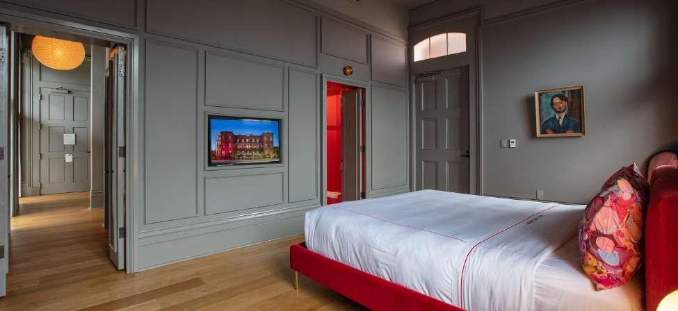
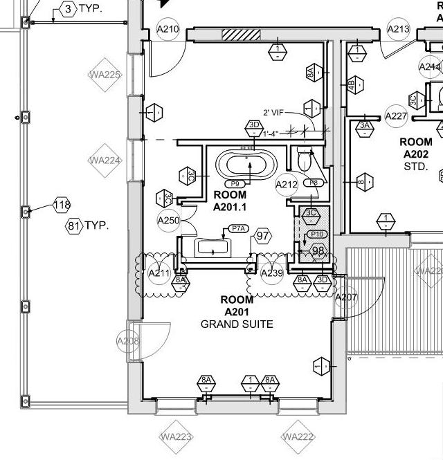
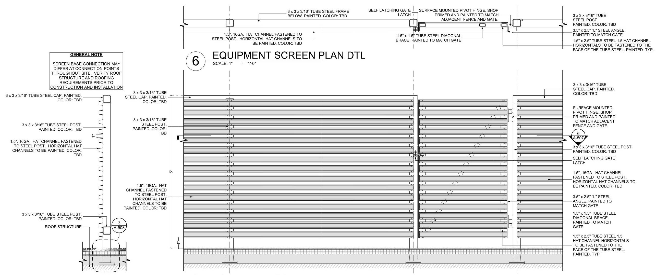
Completed in 2021, Hotel Saint Vincent is an adaptive re-use hotel project located on Magazine Street in New Orleans’s Lower Garden District. MetroStudio provided architectural services to reshape the 1861 asylum campus into a 75 room hotel with three bars, two restaurants, and an event space. I was first introduced to the project during a summer internship at MS in 2018 as the team worked on a 75% CD set for pricing. During this time, I worked on noting plans and elevations, creating wall sections for the new construction buildings, and laying out drawings on the sheets. After my final year of graduate school, I resumed work on the project during its construction, assisting in CA duties. Due to the historic and therefore complex nature of the buildings, the project required the design team to adapt to new conditions discovered during demolition and to get new drawings to the contractor as quickly as possible. During the construction period, I was responsible for writing field reports and drawing details for exterior tile, ceiling assemblies, mechanical screens, and courtyard masonry elements.
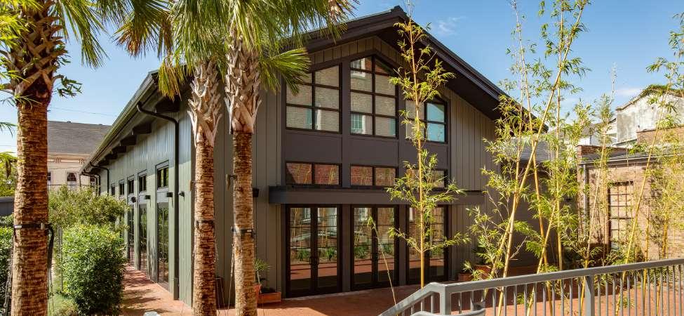
elevation
elevation
event building
east
north

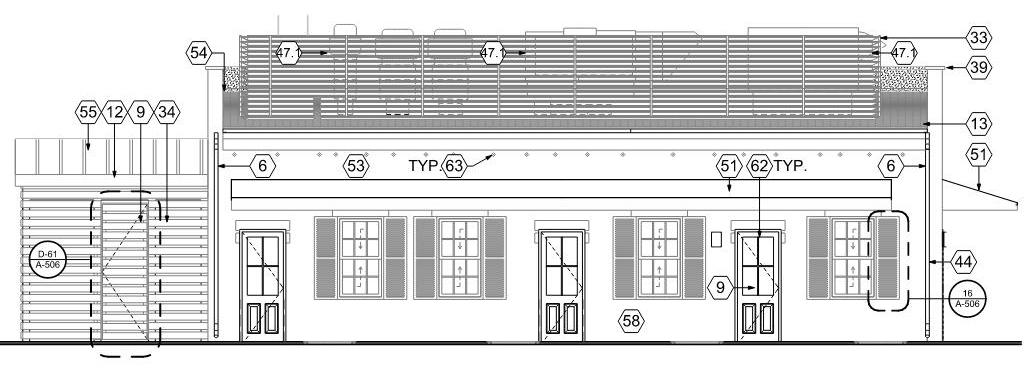
cafe south elevation
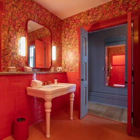
bedroom
bathroom unit plan
equipment screen details
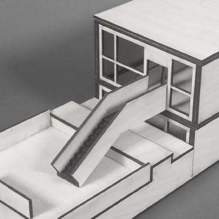
5.2 2.1 3/4" = 1'-0" DETAIL - STAIR PLAN 2
W.3 Affordable Smiles
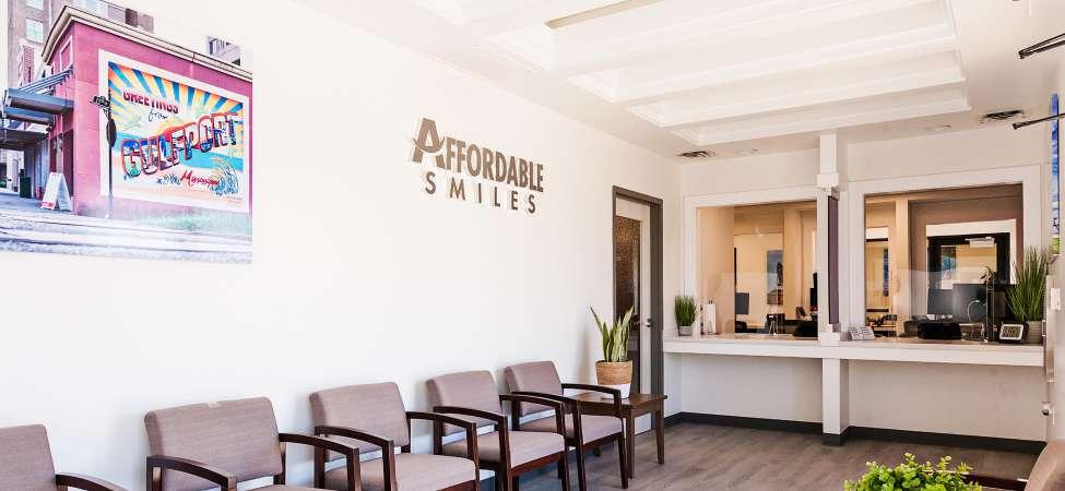
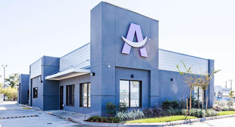
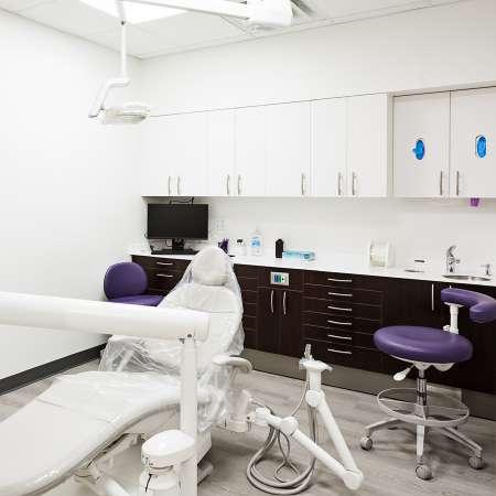
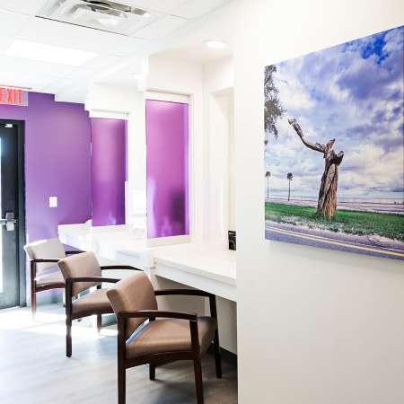
from top: completed west facade, floor plan, waiting room
REVISION ISSUE SHEET TITLE THESE DOCUMENTS HAVE BEEN PREPARED BY ME OR COMPLY WITH ALL CITY REQUIREMENTS PROJECT # #Pln SEAL DATE CONSULTANTS FLOOR PLANS STRUCTURAL CIVIL ENGINEER EHC ENGINEERING LLC 643 MAGAZINE STREET SUITE 300C NEW ORLEANS LA 70130 MECHANICAL PLUMBING ELECTRICAL ENGINEER ADG BATON ROUGE LLC 3071 TEDDY DRIVE BATON ROUGE LA 70809 225 293 9474 DENTAL EQUIPMENT PATTERSON DENTAL 107 MALLARD STREET SUITE D ST ROSE LA 70087 AFFORDABLE SMILES 6501 Spanish Fort Blvd New Orleans LA 70124 504 283 3685 metrostudio net 9310 U S Highway 49 Gulfport Mississippi 39503 NOT FOR CONSTRUCTION F W01 104 103 W04 W05 W09 W08 106 102 109 CO19 CO15 CO16 CO17 CO18 CO12 CO14 CO13 CO20 118 101 105 108 107 115 CO11 114 110 CO7 CO6 CO5 CO4 CO3 CO1 117 CO9 CO10 116 113 111 112 CO22 DR F DW A-506 A-506 3 A-506 3 A-506 A-506 1 A-506 1 A-4012 -501A-501 A-501 2 A-501 2 A-501 2 A-502 2 A-502 1 A-501 1 A-501 2 -501 2 A-501 2 A-501 2 A-501 1 A-502 1 A-502 A-211 A-211 1 A-211 1 A-211 3 A-503 3 A-503 2 A-503 A-503 2 A-504 A-504 3 A-504 3 A-504 2 A-504 A-504 2 A-201 1 A-202 -202 1 -201 4 A-202 7 A-202 1 3 A-301 7 5 A-301 14 16 A-301 21 22 23 24 A-301 17 18 19 20 A-301 25 26 27 28 A-301 29 30 31 32 A-301 10 11 12 13 A-302 14 15 16 17 A-302 33 34 35 A-301 18 19 20 21 A-302 22 23 24 A-302 1 2 A-302 3 4A-302 26 27 28 A-302 1111 -11A211111 - - -1 -1 1 1---1 1 1 1111111A-1A111A1-11111 -11111EQ4 P08 P07 P02 P01 03 P04 EQ2 P11 EQ4 EQ P05 P06 P09 EQ SIM SIM TYP SIM SIM TYP TYP SIM WAITING AREA 100 CONSULT OFFICE 113 STERILIZATION 122 MECHANICAL 127 SCANNING 110 RESTROOM 111 RESTROOM 106 B O CHECK OUT 125 IT 123 BUSINESS MANAGER 124 CLINIC LEAD 101 LAB 126 DOCTOR S OFFICE 116 MED GAS 108 STAFF LOUNGE 121 TR 5 109 TR 1 102 TR 2 103 TR 3 104 TR 4 105 SX 2 118 TR 7 115 SX 1 117 TR 6 114 SX 3 119 CLOSET 107 CORRIDOR 112 9 9 9 9 2 9 8 8 15 17 11 12 3 9 9 10 4 5 5 5 5 1 6 7 7 2 18 14 13 2 7 9 9 18 7 7 7 19 20 20 20 20 21 1 A-503 A-503 1FLOOR PLAN KEYNOTES GENERAL NOTES 11 12 14 17 18 1 CONTRACTOR SHALL REFER TO ALL GENERAL NOTES ON SHEET G101 2 CONTRACTOR TO LAY OUT ALL WORK AND COORDINATE ALL BUILDING SYSTEMS CONTRACTOR SHALL VERIFY COORDINATION OF ALL BUILDING SHALL NOTIFY DESIGN TEAM OF POTENTIAL CONFLICTS 3 REFER TO 600 SHEETS FOR ALL LEGENDS AND 4 REFER TO LS-101 FOR ADDITIONAL INFORMATION 5 ALL EXPOSED STEEL TO BE PAINTED WITH DTM PAINT COLORS TBD FROM FULL RANGEADDITIONAL INFORMATION 7 ALL MATERIALS AND COLORS OF MATERIALS LISTED AS SHALL PICKED FROM RANGE OF MATERIALS AND COLORS 20 21 15 23 24 26 27 OSHA COMPLIANT GALVANIZED STEEL LADDER CAGE & LOCKABLE GATE SOUND BATT INSULATION SLIDING DOOR & TRACK SEE INTERIOR ELEVATIONS FOR MORE INFO X X X X X X X X X X X X X X X X X X X X X X X X X APPLY FLOOR PATCH AS REQUIRED TO LEVEL EXISTINGCOORDINATE WITH NEW EXISTING OPENINGS OWNER FURNISHED F F E OWNER FURNISHED SEE ELECTRICAL FOR POWER & DATE REQUIRMENTS OWNER SUPPLIED COPY MACHINE SEE ELECRICAL FOR POWER REQUIREMENTS SALSBURY INDUSTRIES 65358GY-U FIVE TIER BOX STYLE LOCKER EXISTING HOSE BIB LOCATION SEVILLE CLASSICS ULTRA HD TALL STORAGE CABINET COMPUTER LOCATION SEE ELECTRICAL FOR POWER EXISTING BOLLARD TO COLOR ). DENTAL EQUIPMENT SEE DENTAL DRAWINGS FLOOR DRAIN SEE PLUMBING DRAWINGS 3-FORM WALL PARTITION SEE SHEET A-504 MILLWORK SEE INTERIOR ELEVATIONS & MILLWORK DETAILS NEW ELECTRICAL GEAR SEE ELECTRICAL DRAWINGS NEW CONCRETE FLAT WORK OR FOUNDATION SEE STRUCTURAL DRAWINGS CANOPY ABOVE SEE SETIONS TR SX PARTITION DETAIL SEE SHEET A-601 OWNER SUPPLIED PAPER SHREDDER SEE ELECRICAL FOR POWER REQUIREMENTS 4 A-503 -503A-202 1 A-201 A-201 7 N FLOOR PLAN FOR REVIEW AND APPROVAL 09 22 2020 FLOOR PLAN FOR REVIEW AND APPROVAL 09 24 2020 ISSUED FOR BANK SUBMISSION 09 28 2020 SCALE 4 = 1 -0 1 1st FLOOR PLAN SCALE 1 " = 1 -0 3 MONUMENT SIGN PLAN
A-101
post-demolition
W.3 Affordable Smiles - Gulfport, MS
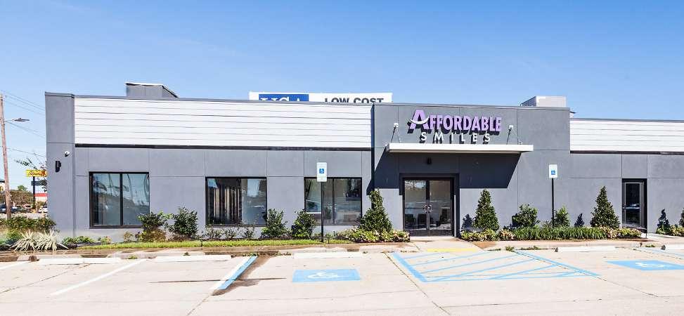
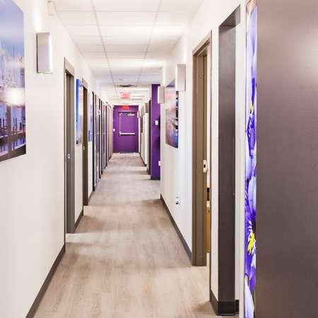
One of the strangest projects I’ve had the opportunity to work on, Affordable Smiles is a dentist office which occupies the shell of a former Chinese drive-thru. The regional dentistry chain Affordable Smiles approached MetroStudio to refurbish the 1990’s building to serve as their first out of state location. While the client had hoped the scope of the project would be limited to replanning the interior and repainting the exterior, selective demolition revealed leaking/moisture in the walls due to improper stucco detailing when the building was constructed. In the end, the exterior walls were stripped down to the sheathing, new waterproofing was applied, and the building was finished with entirely new stucco and Hardie siding. Peculiar elements of the contemporary fast food building typology such as the looping driveway and the drive-thru windows were retained to lower the overall project cost. Curiously, these formal elements help the building remain a part of the Hwy 49 commercial corridor; while the chosen colors, dark grey and the brand’s royal purple, make it stand out from the neighboring Arby’s and Krispy Kreme.
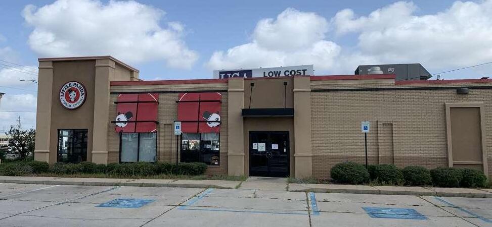 existing south facade
completed south facade
demo south elevation
issued for permitting south elevation
4 WEST ELEVATION
final model final south elevation
17 1 13 13 13 6 6 16 4 1 16 8 8 8 13 SQFT / 63 SQFT ALLOWABLE CANOPY SIGN EXISTING TOWER OUTLINE TYP TYP TYP 12 9 9 8 16 18 SQFT FREESTANDING 5 -0" ELEVATION 17 13 1 13 13 6 4 5 10 12 6 20 20 TYP 9 17 1 13 13 13 6 6 8 11 16 16 4 12 5 18" TYP. TYP TYP FINISHES AS REQUIRED BY PAINTED WITH EXTERIOR AND PREPARE ALL SURFACES SELECTED FROM FULL RANGE TBD SHALL BE SELECTED STUCCO TO MATCH NEW 9 17 8 16 18 -0 ELEVATION -0" ELEVATION 4 3 9 4 5 11 6 1 1 1 2 2 16 16 TYP TYP TYP TYP 7 13 3 2 15 1 1 2 2 14 3 4 5 3 3 3 4 14 18" TYP. TYP TYP TYP TYP TYP TYP 12 5 1 13 TO BE REMOVED REPLACED OR REPAINTED TO BE REMOVED CONTRACTOR MATCH NEW CONSTRUCTION REMOVED REMOVED REMOVED AT ADDITION REPLACED WITH CODE -COMPLIANT REMOVED AT ADDITION REMOVED CONTRACTOR TO PATCH CONSTRUCTION AND ADJACENT PARTITION TO BE REMOVED FOR NEW BE REMOVED RESHAPED TO SPECIFIED DETAILS RESHAPED TO SPECIFIED DIMENSIONS TO BE REMOVED REPLACED REMOVED AND REPLACED -0 ELEVATION SCALE: 1/4" = 1 -0 2
-0 ELEVATION SCALE: 1/4" = 1 -0
EAST ELEVATION
check out counter detail
SECTION @ CHECK-IN COUNTER office
3
corridor office treatment room

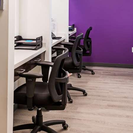
REVISION / ISSUE # SHEET TITLE: THESE DOCUMENTS HAVE BEEN PREPARED BY ME OR UNDER MY CLOSE PERSONAL SUPERVISION AND THEY COMPLY WITH ALL CITY REQUIREMENTS SEAL DATE CONSULTANTS WALL SECTIONS STRUCTURAL/CIVIL ENGINEER EHC ENGINEERING LLC 643 MAGAZINE STREET SUITE 300C NEW ORLEANS LA 70130 504 372 1047 MECHANICAL/PLUMBING/ELECTRICAL ENGINEER ADG BATON ROUGE LLC 3071 TEDDY DRIVE BATON ROUGE LA 70809 225 293 9474 DENTAL EQUIPMENT PATTERSON DENTAL 107 MALLARD STREET SUITE D ST ROSE LA 70087 504 463 1770 AFFORDABLE
6501 Spanish Fort Blvd, New Orleans, LA 70124 504 283 3685 // www metrostudio net 9310 U S Highway 49, Gulfport, Mississippi 39503 NOT FOR CONSTRUCTION 4" 1/4" 4'-5" 1/4" 4" 2'-10" 1'-2" 3'-11 1/2" 1'-5 3/4" 1" CT-1 COUNTERTOP, SEE FINISH LEGEND SHEET A-604 CUSTOM MILLWORK WITH PL-1 FINISH SEE MILLWORK DETAILS FOR MORE INFO WD-1 WINDOW HEAD CASING, JAMB & SILL SIMILAR PTD COLOR TBD CT-1 COUNTERTOP, SEE FINISH LEGEND SHEET A-604 CEILING FUR-DOWN AT CHECKOUT SEE DETAIL 13 A-504 FOR MORE INFO WD-1 CASING PTD COLOR TBD 3-FORM 200 25 BASE PROFILE 3-FORM FRAMELSS TOP AND BOTTOM CHANNEL PARTITION 200 25 VARIA PANEL COLOR TBD 3-FORM 200 25 BASE PROFILE PAINTED GYPSUM 2x4" FRAMING SUPPORT FOR COUNTERTOP PTD COLOR TBD WD-1 APRON PTD COLOR TBD PAINTED GYPSUM BOARD WALL BEYOND FINISH FLOOR 4" 1/4" 3'-11 1/2" 1/4" 4" 1'-10" 2'-10" 1" 1'-6" 3'-6" 1'-2 1/8" CT-1 COUNTERTOP, SEE FINISH LEGEND SHEET A-604 WD-1 WINDOW HEAD CASING JAMB & SILL SIMILAR ALL MILLWORK TO BE PL-1 FINISH SEE FINISH LEGEND SHEET A-604 CT-1 COUNTERTOP SEE FINISH LEGEND SHEET A-604 5/8" PAINTED GYPSUM BOARD 5/8" PAINTED GYPSUM BOARD PAINTED GYPSUM BOARD WALL BEYOND 2x4" FRAMING SUPPORT FOR COUNTERTOP, PTD COLOR TBD WD-1 APRON, PTD COLOR TBD 3-FORM 200 25 BASE PROFILE 3-FORM FRAMELSS TOP AND BOTTOM CHANNEL PARTITION 200 25 VARIA PANEL COLOR TBD 3-FORM 200 25 BASE PROFILE WD-1 CASING PTD COLOR TBD PAINTED GYPSUM BOARD WALL BEYOND FINISH FLOOR SEE SCHEDULE FOR MORE INFO SHEET A-604 3' 11' SCALE: 3/4" = 1 -0
SMILES
W.4 100 Oriole
-
floor plan south elevation
W125 W124 DW W DR W134 W132 W133 W137 W136 W135 126 113 CO3 116 104 W140 W115 120 119 130 128 126 122 125 124 132 CO4 102 CO 134 W118 W119 112 133 109 115 W113 W141 101 1 2 3 3 4 3 5 5 6 6 7 9 9 8 8 10 10 12 11 12 12 13 14 16 14 17 19 19 18 18 18 18 18 18 120 18 A-501 20210'-0" (REF. 5.00' NAVD) -6" 0'-0" (REF. 5.00' NAVD) -1' 0'-0" (REF. 5.00' NAVD) -6" -6" -1' -1' A-302 A-302 1 A-3022 A-302 A-302 A-301 -301 A-303 A-303 A-3126 A-314 -314 5A-314 A-314 A-314 9 A-314 A-201 2A-202 13 -202 01 03 1 -2100302 04 -210 02 04 22 A-210 0301 03-01 03010101 0302 04 18 -211 01 0301 03P02 P03 P03 P05 P06 P07 P08 P10 P23-P28 P12 P36 P37 P14 P15 P14 P16 P18 P01 P19 P20 EQ01 EQ02 EQ04 EQ03 EQ05 EQ06 EQ09 EQ07 P08 TA07 TA03 TA04 TA09 TA12 TA05 TA05 P21 TA06 TA03 TA01 TA10 TA11 P22 P11 EQ10 TA14 TA13 P35 TA08 P17 EQ11 EQ14 EQ12 EQ16 EQ13 EQ17 EQ18UP GENERATOR CU 1 CU 2 POOL BY RAISED HOT TUB BY OTHERS BENCH W105 W104 SLOPE W110 W109 W108 GARAGE WORKSHOP 128 BEDROOM2 111 BEDROOM BATH 2 129 WIC 1 WIC 2 BATH 1 114 LAUNDRY HVAC PDR 107 PANTRY FOYER ENTRY BREEZEWAY POOL EQUIP 130 110 KITCHEN FAMILY ROOM 118 PORCH E02 CLOSET FOYER CLOSET STORAGE 131 MASTER BATH MASTER CLOSET 127 LINEN CLOSET 125 120 M B W C 124 M B SHOWER 126 J & J 1 J & J 2 VESTIBULE 121 PLACE 132 CORRIDOR SITTING ROOM 119 MASTER BEDROOM 105 106 110 111 W131 W130 W129 108 127 132 1 A-305 A-305 A-301 A-301
2-305 -305 -304
A-304 A-304 77A-201 01 03P01 P04 P04 P09 P38 P13 P09 TA02 TA02 EQ08 P29 P30-P31 TA16 TA17 VANITY W101 W116 W206 13 1302 04 26 A-210 LOFT 201 OPEN TO BELOW A-303 A-305 A-305 W204 LOFT BALCONY E03 SCALE 1 4" = 1 -0 1 1ST FLOOR PLAN SCALE 2 2ND
-
CONSULTANTS STRUCTURAL ENGINEER EHC ENGINEERING LLC 643 MAGAZINE STREET SUITE 300 NEW ORLEANS LA 70130 504 372 1047 GREGORY RESIDENCE 6501 Spanish Fort Blvd New Orleans LA 70124 504 283 3685 // www metrostudio net 100 ORIOLE STREET NEW ORLEANS LA 7 TYP BLDG TOP PLATE BLDG TOP PLATE 15 -0 BLDG TOP PLATE 19 -4 3 4 HIGHEST MEDIUM ROOF HEIGHT 21 -10 46 40 12 7 1 63 10 8 20 20 64 65 46 83 83 83 83 84 85 86 5' 3' W112 W111 W106 W107 TYP TYP TYP TYP TYP BLDG 1ST FLOOR T O C 0 -0 REF 5 00 NAVD T O PAVER @ POOL DECK (-) 12 GARAGE FLOOR PORCH & ENTRY BREEZEWAY T O C (-) BLDG TOP PLATE 9BLDG TOP PLATE 10LOFT T O SUB-FLOOR 10 -4 3 BLDG TOP PLATE 11BLDG TOP PLATE 14BLDG TOP PLATE 15HIGHEST MEDIUM ROOF HEIGHT 21 -10 100 5 28 29 4 SCALE 1 4" 1 -0 1 SOUTH ELEVATION
wall section at fireplace
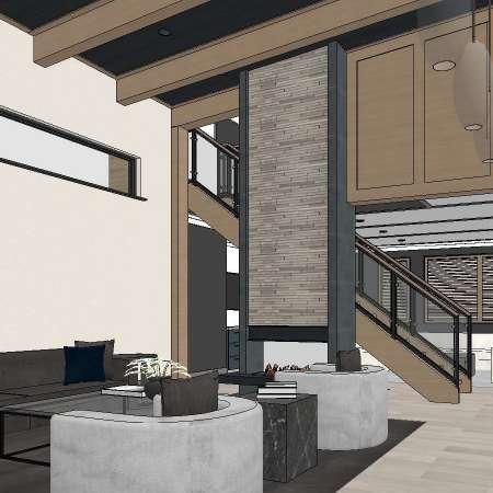
living room
04 04
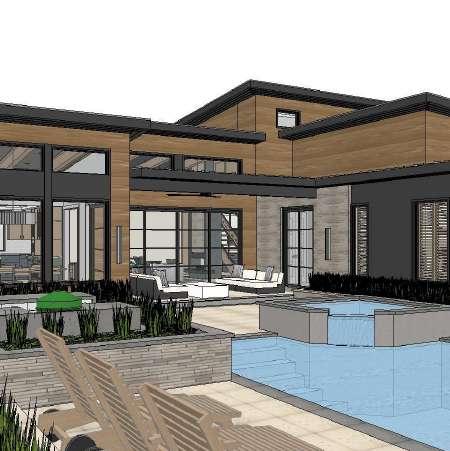
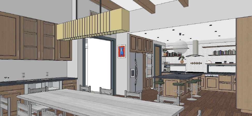
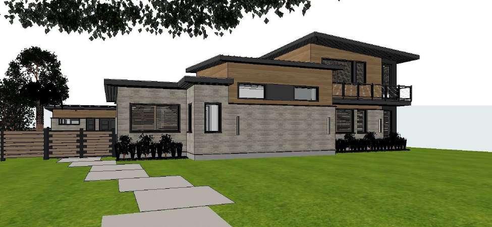
W.4 100 Oriole St. - New Orleans, LA 100 Oriole St is a single-family home located in the historic modernist neighborhood of Lake Vista. Our clients had occupied a 1980’s ranch house on the site for years and hired MetroStudio to design a similar but contemporary house to replace it. Our team retained the existing (to-be-demolished) house’s excellent siting and privacy strategies but overhauled the interior layout to remove inefficiencies and out-of-fashion space planning. This project stands out from others in my career as the project that yielded the most collaboration with the clients: retirees who were able to select all finishes, fixtures, etc down to the cabinet pulls prior to the contractor bidding the job. Their investment in the outcome of the project helped us to create one of the most detailed drawing sets to come out of our office. By the same token, their understanding of the historicity of the neighborhood allowed us to design a contemporary structure in the lineage of and in homage to the area’s mid-century homes. Unfortunately, changes in the market due to the coronavirus put the project out of budget and it remains unbuilt.
04
1 41 21 2 10 26 9 3 27 4 69 36 24 11 38 70 55 70 55 9 37 68 26 26 31 1 41 21 2 10 26 38 38 71 19 20 10 A-501 16 A-501 11 A-501 9' FRAMING HEIGHT 3 1/8" BLDG 1ST FLOOR T O C 0 -0 REF 5 00 NAVD) T O LOFT SUB-FLOOR 10 -4 3 4 BLDG TOP PLATE VARIES (SLOPED ROOF EAVE HEIGHT VARIES (SLOPED MIRROR 9 A-501 4'-4" FRAMED OPENING 2" MIN. 2'-2" 3 1/2" 24 11 10 26 38 A-501 16 501 BLDG TOP PLATE VARIES SLOPED) ROOF EAVE HEIGHT VARIES SLOPED) SLOPE 1/4 12 T O LOFT SUB-FLOOR 10 -4 3 4 BALCONY T O SUB-FLOOR 10 -0 1 41 21 2 26 38 50 24 17 A-501 10' FRAMING HEIGHT SCALE: 3/4" = 1 -0 1 W S THRU FIRE PLACE SCALE: 3/4" = 1 -0 2 W S
4
THRU BALCONY
entry gate detail
patio southwest elevation 60 61 60 60 60 60 61 60 61 61 6" 3 1/2" 2" 5" 8'-4 3/4" 3" 3 1/2" 6" 4 1/2" 6" 4 1/2" 3'-6" 4 1/2" 6" 1/2" 6" 3 1/2" 4 1/2" 2 1/4" 1'-6 1/2" 10 1/2" 1'-7 1/2" 1'-7 1/2" 10 1/2" 10 1/2" 9 1/2" 2" 9 1/2" 2'-1 1/4" 2 1/2" 2'-1 1/4" 9 1/2" 2" 6'-4" 1 1/2" 1 1/2" 3" 1 1/2" 3" 3" 4" 1 1/2" 4 1/2" 3 1/2" 6" 4 1/2" 6" 4 1/2" 1'-2" 4 1/2" 6" 4 1/2" 6" 3 1/2" 4 1/2" 6" 6" TOP OF PAVER STEEL ATTACHMENT LEG LENGTH MAY VARY F V.) STEEL ATTACHMENT LEG LENGTH MAY VARY F V.) ENTRY BREEZEWAY ENCLOUSRE GATE ELEVATION SECTION DETAIL (LOOKING FROM EXTERIOR YARD SIDE NOTE: CONTRACTOR SHALL PROVIDE F V SHOP DRAWINGS FOR ARCHITECTS REVIEW PRIOR TO CONSTRUCTION CONRACTOR SHALL PROVIDE LATCHING LOCKING HARDWARE w RECESSED BOX FOR KEYING 1 2 9 3 4 5 11 12 6 7 8 10 13 14 15 17 16 18 19 20 21 22 23 24 25 26 27 28 29 30 31 32 33 34 35 GENERAL NOTES 1 ALL MATERIALS SHOWN SHALL BE PREPED AND INSTALLED PER MANUFACTURERS GUIDELINES AND SPECIFICATIONS 2 ALL PROJECT ELEVATIONS ARE BASED ON OWNER PROVIDED SURVEY AND CONSTRUCTION BENCHMARK VERIFY PRIOR TO CONSTRUCTION WITH SURVEY AND CONSTUCTION BENCH MARK 3 ALL WOOD ELEMENTS EXPOSED TO MOISTURE IN CONTACT WITH CONCRETE AND OR MASONRY SHALL BE PRESSURE TREATED 4 REFER TO DOOR & WINDOW MANUFACTURER S REQUIREMENTS ALL ROUGH OPENINGS 5 REFER TO SHEET A-600 FOR FINISH SCHEDULE AND LEGEND 6 ALL FRAMING MEMBERS SHOWN ARE SHOWN FOR REFERENCE VERIFY SIZE AND SPACING WITH STRUCTURL 7 FASTNERS ARE REMOVED FROM DETAILS FOR CLARITY INSTALL MANUFACTURERS RECOMENDATIONS 8 CONTRACTOR TO PROVIDE ALL FURRING WOOD GROUNDS WOOD BLOCKING AND ROUGH CARPENTRY AS REQUIRED FOR MATERIAL FIXTURE MOUNTING IN ACCORDANCE WITH ALL MANUFACTURER REQUIREMENTS 9 ALL DIMENSIONS ARE TO FINISH FACE OF WALL TYP 10 ALL SPACES THAT INCORPORATE WALL TILE SHALL HAVE CB-1 11 DETAILS MAY BE EXAGGERATED FOR CLARITY 12 SEE STRUCTURAL FOR ALL HURRICANE STRAPPING AND UPLIFT CONNECTIONS 13 ELEVATION HEIGHTS ARE ONLY SHOWN FOR LOWER PLATE HEIGHTS OF SLOPED ROOFS SEE SECTIONS FOR ADD INFO 14 AT SOFFIT PROJECTIONS AND ROOFS OVER NON-CONDITIONED SPACE ONLY ZIP SHEATHING SHALL BE USED 15 AT HEAD WALL & RAKE WALL CONDITIONS ICE & WATER SHIELD SHALL CONTINUE UP ADJACENT WALL BY A MIN OF 12 16 ATTICS & ENCLOSED RAFTER SPACES SHALL COMPLY / IRC 2015 SECTION R806 5 ELEVATION SECTION KEYNOTES 2x WOOD FRAMING SEE STRUCTURAL TYP 3 4 MIN FLOOR SHEATHING SEE STRUCTURAL TYP SQ CUT FIBER CEMENT FASCIA TYP PAC-CLAD TITE-LOC STANDING SEAM ROOFING ZIP SYSTEM R-SHEATHING R-9 ROOF PANEL w 5 8 SHEATHING WIPE CLEAN JOINTS WEATHER LAP & TAPE ALL JOINT & PENETRATIONS ROLL ALL JOINTS TYP EWP1 - WALL PANEL SEE FINISH LEGEND TYP ZIP SYSTEM R-SHEATHING R-3 WALL PANEL w 1 2 SHEATHING WIPE CLEAN JOINTS WEATHER LAP & TAPE ALL JOINT & PENETRATIONS ROLL ALL JOINTS TYP EMV1 - MASONRY VENEER SEE FINISH LEGEND TYP ESP1 - SOFFIT PANELS SEE FINISH LEGEND ESP2 - SOFFIT PANELS SEE FINISH LEGEND EMV2 - MASONRY SPECIAL SHAPE SEE FINISH LEGEND TYP STRUCTURAL MEMBER (CHANNEL I-JOIST CEILING JOIST RAFTER BEAM HEADER ETC..) SEE STRUCTURAL TYP KYNAR COATED METAL FLASHING COLOR TBD TYP CLOSED CELL BACK ROD w SEALANT 1 2 THK SELF-ADHERING FLASHING TAPE TOTAL FLASH MASONRY CAVITY WALL DRAINAGE SOLUTION TYP @ ALL MASONRY LOCATIONS MILLWORK SEE DETAILS TYP POLY GUARD PRODUCTS TERM SILL MOISTURE / TERMITE BARRIER TYP 10 MIL VAPOR BARRIER TAPE ALL JOINTS SEAL ALL PENETRATIONS TYP FOUNDATION SYSTEM SEE STRUCTURAL TYP GAF STORM GUARD ICE GUARD & LEAK BARRIER FOR METAL ROOFS TYP PRESSURE TREATED SOLE PLATE w SILL SEALER FOAM GASKET TYP WEEP HOLE @ 24" O C w/ INSECT SCREEN FLOORING SEE FINISH SCHEDULE & LEGEND TYP GALVANIZED DW-10HS VENEER ANCHOR @ 16" O C E W TYP @ ALL MASONRY LOCATIONS R-38 ECOBATT KRAFT FACED HIGH DENSITY FIBER GLASS BATT INSULATION TYP @ ROOF LOCATIONS R-19 FRAFT FACED FIBER GLASS BATT INSULATION TYP @ WALL LOCATIONS WINDOW SEE SCHEDULE & LEGEND TYP DOOR CASED OPENING SEE SCHEDULE & LEGEND TYP EQUIPMENT SEE PLANS & SCHEDULE CUSTOM STAIR AND OR RAILING ASSEMBLIES SEE DETAILS PLUMBING FIXTURE SEE SCHEDULE & PLANS SIMPSON STRONG TIE WIND CONNECTOR SEE STRUCTURAL ANCHOR BOLT SEE STRUCTURAL FRY REGLET T" MOLDING BUFFED BRITE DARK BRONZE SCALE 1" = 1 -0 1 BREEZEWAY ENCLOSURE DETAILS

A-310 BLDG 1ST FLOOR 0 -0" REF 5 00 T O PAVER @ POOL GARAGE FLOOR PORCH ENTRY BREEZEWAY T O BLDG TOP LOFT T O SUB-FLOOR 10 -4 BLDG TOP BLDG TOP PLATE 19 -4 3 4 BLDG TOP 2 A-314 1 A-314 3 A-314 BLDG 1ST FLOOR T O C 0 -0" REF 5 00 NAVD T O PAVER @ POOL DECK (-) 12 GARAGE FLOOR PORCH & ENTRY BREEZEWAY T O C (-) 6 BLDG TOP PLATE 11 -0 BLDG TOP PLATE 14 -0 SCALE 1 2" = 1 -0 1 SECTION THROUGH SITTING ROOM AND PORCH SCALE 1 2" = 1 -0 2 SECTION THROUGH KITCHEN AND DINING SCALE: 1:114.39
millwork details section at kitchen and dining kitchen and dining 5 13 7 8 9 11 12 14 15 16 17 18 6 18 30 3' 1 1/4" 1'-9" 2' 1'-6" 1'-11" 4" 1'-6" 5 13 7 8 9 11 12 14 15 16 17 18 1 6 18 30 11 A-503 3' 1 1/4" 1'-9" 3'-6" 1'-2" 1'-8" 1'-11" 4" 5 7 8 9 11 14 16 17 18 1 6 18 22 3' 1 1/4" 1'-8" 4" 1'-11" 7 8 9 11 14 16 17 18 6 18 30 5'-6" 2'-10 1/4" 1'-10" 4" 2'-1" 17 18 SCALE: 1 = 1 -0 1 SECT @ KITCHEN SCALE: 1 = 1 -0 2 SECT @ KITCHEN SCALE 1" = 1 -0 3 SECT @ KITCHEN SINK SCALE 1" = 1 -0 4 SECT @ KITCHEN SCALE 5 SECT 5 13 7 8 9 11 12 14 15 16 17 18 6 18 30 3' 1 1/4" 1'-9" 2' 1'-6" 1'-11" 4" 1'-6" 5 13 7 8 9 11 12 14 15 16 17 18 1 6 18 30 11 A-503 3' 1 1/4" 1'-9" 3'-6" 1'-2" 1'-8" 1'-11" 4" 5 7 8 9 11 14 16 17 18 1 6 18 22 3' 1 1/4" 1'-8" 4" 1'-11" 7 8 9 11 14 16 17 18 6 18 30 5'-6" 2'-10 1/4" 1'-10" 4" 2'-1" 13 7 9 11 17 18 6 18 30 2'-1" 1'-11" SCALE 1 = 1 -0 1 SECT @ KITCHEN SCALE 1" = 1 -0 2 SECT @ KITCHEN SCALE: 1" = 1 -0 3 SECT @ KITCHEN SINK SCALE 1" = 1 -0 4 SECT @ KITCHEN SCALE: 1 = 1 -0 5 SECT @ KITCHEN 5 13 7 8 9 11 12 14 15 16 17 18 6 18 30 3' 1 1/4" 1'-9" 2' 1'-6" 1'-11" 4" 1'-6" 5 13 7 8 9 11 12 14 15 16 17 18 1 6 18 30 11 A-503 3' 1 1/4" 1'-9" 3'-6" 1'-2" 1'-8" 1'-11" 4" 5 7 8 9 11 14 16 17 18 1 6 18 22 3' 1 1/4" 1'-8" 4" 1'-11" 7 8 9 11 14 16 17 18 6 18 30 5'-6" 2'-10 1/4" 1'-10" 4" 2'-1" 13 7 8 9 11 12 14 15 16 17 18 6 18 30 1'-2 1/2" 4" 2'-10 1/4" 2'-1" 1'-11" SCALE: 1 = 1 -0 SECT @ KITCHEN SCALE 1 = 1 -0 2 SECT @ KITCHEN SCALE 1" = 1 -0 3 SECT @ KITCHEN SINK SCALE 1" = 1 -0 4 SECT @ KITCHEN SCALE: 1" = 1 -0 5 SECT @ KITCHEN OVEN 5 8 12 14 15 16 18 3' 1 1/4" 1'-9" 2' 1'-6" 1'-11" 4" 5 13 7 8 9 11 12 14 15 16 17 18 1 6 18 30 11 A-503 3' 1 1/4" 1'-9" 3'-6" 1'-2" 1'-8" 1'-11" 4" 5 7 8 9 11 14 16 17 18 1 6 18 22 3' 1 1/4" 1'-8" 4" 1'-11" 7 8 9 11 14 16 17 18 6 18 30 5'-6" 2'-10 1/4" 1'-10" 4" 2'-1" 13 7 8 9 11 12 14 15 16 17 18 6 18 30 1'-2 1/2" 4" 2'-10 1/4" 2'-1" 1'-11" KITCHEN SCALE 1" = 1 -0 2 SECT @ KITCHEN SCALE: 1 = 1 -0 3 SECT @ KITCHEN SINK SCALE: 1" = 1 -0 4 SECT @ KITCHEN SCALE: 1 = 1 -0 5 SECT @ KITCHEN OVEN 3' 1 1/4" 1'-9" 2' 1'-6" 4" 5 13 7 8 9 11 12 14 15 16 17 18 1 6 18 30 11 A-503 3' 1 1/4" 1'-9" 3'-6" 1'-2" 1'-8" 1'-11" 4" 5 7 8 9 11 14 16 17 18 1 6 18 22 3' 1 1/4" 1'-8" 4" 1'-11" 7 8 9 11 14 16 17 18 6 18 30 5'-6" 2'-10 1/4" 1'-10" 4" 2'-1" 13 7 8 9 11 12 14 15 16 17 18 6 18 30 1'-2 1/2" 4" 2'-10 1/4" 2'-1" 1'-11" 1 2 3 4 5 6 7 8 9 10 11 12 13 14 15 16 17 18 19 20 21 22 23 24 25 26 27 28 29 30 GENERAL NOTES 1 VERIFY ALL DIMENSIONS FABRICATION TYPICAL 2 REFER TO STRUCTURAL 3 ALL DETAILS TO 4 SUBMIT SHOP DRAWINGS FABRICATION 5 NOTIFY ARCHITECT PRIOR TO COMMENCING 6 FILLER STRIP DIMENSIONS 7 ENSURE REQ CLEARANCES TYP 8 HINGE AND OVERLAY CONDITIONS CABINETS 9 SUBMIT SAMPLES BEFORE COMMENCING IN THE JOB IF APPROVED 10 REFER TO SHEET 11 REFER TO MANUFACTURER FIXTURE S ROUGH 12 LAUNDRY MILLWORK INSTALLED ADJUSTABLE EDGE BANDS SHELVES DEPICTED WALL BASE SEE CROWN MOLDING 2X ADDITIONAL CABINET DRAWER 3 4 X 2 1 2" HARDWOOD 1 4 PLYWOOD 1 4 HARDBOARD 3 4 HARDWOOD 1 2 HARDWOOD HOLES & HARDWARE 3 4 PLYWOOD 3 4 HARDWOOD SCHEDULED APPLIANCE SCHEDULED PLUMBING 1 2 PLYWOOD WOOD BLOCKING 3 4 HARDWOOD BACKSPLASH SCHEDULE TYP COUNTER MATERIAL WALL SURFACE PULL OUT LAUNDRY 3 4 HARDWOOD TOILET ACCESSORY FACE OF MILLWORK ADJUSTABLE 1" IF OVER 3 CONTRACTOR METAL CLOTHES SEE WALL SECTIONS EXTERIOR MILLWORK NATUREKAST FUR DOWN GRAPHICS DETAILS AND CROWN DIMENSIONS SCALE: 1 = -0 2 SECT @ KITCHEN SCALE 1" = 1 -0 3 SECT @ KITCHEN SINK SCALE 1" = 1 -0 4 SECT @ KITCHEN SCALE 1" = 1 -0 5 SECT @ KITCHEN OVEN
1 Generic Perspective
04 04 east
north
north
entry A-202 REVISION ISSUE # SHEET TITLE THESE DOCUMENTS HAVE BEEN PREPARED BY ME OR UNDER MY CLOSE PERSONAL SUPERVISION AND THEY COMPLY WITH ALL CITY REQUIREMENTS PROJECT # #Pln SEAL DATE CONSULTANTS ELEVATIONS ISSUED FOR REVIEW 11 15 2021 ISSUED FOR BIDDING PERMITTING 04 18 2022 STRUCTURAL ENGINEER EHC ENGINEERING LLC 643 MAGAZINE STREET SUITE 300C NEW ORLEANS LA 70130 504 372 1047 GREGORY RESIDENCE 6501 Spanish Fort Blvd New Orleans LA 70124 504 283 3685 // www metrostudio net 100 ORIOLE STREET NEW ORLEANS LA 46 40 12 7 1 63 10 8 20 64 64 46 40 10 64 83 83 83 83 W137 W136 W135 W138 W139 W202 TYP TYP TYP TYP TYP TYP BLDG TOP PLATE 9 -0 BLDG TOP PLATE 10 -0 LOFT T O SUB-FLOOR 10 -4 3 4 BLDG TOP PLATE 11 -0 BLDG TOP PLATE 14 -0 15 -0 BLDG TOP PLATE 19 -4 3 4 HIGHEST MEDIUM ROOF HEIGHT 21 -10 28 29 4 5 29 46 65 40 7 1 8 20 31 4019W203 W204 W121 W120 W122 W123 W119 TYP TYP TYP TYP BLDG 1ST FLOOR T O C 0 - " REF 5 00 NAVD GARAGE FLOOR PORCH & ENTRY BREEZEWAY T O C (-) 6 BLDG TOP PLATE 9 -0 BLDG TOP PLATE 10 -0 LOFT T O SUB-FLOOR 10 - 3 4 BLDG TOP PLATE 11 -0 BLDG TOP PLATE 14 -0 BLDG TOP PLATE 15 -0 BLDG TOP PLATE 19 - 3 4 HIGHEST MEDIUM ROOF HEIGHT 21 -10 5 28 29 4 46 8 20 7 63 64 10 12 65 83 TYP SEE SECTIONS WALLS SECTIONS BLDG 1ST FLOOR T O C 0 -0 REF 5 00 NAVD T O PAVER @ POOL DECK (-) 12 ENTRY BREEZEWAY T O C (-) 6 BLDG TOP PLATE 9 -0 BLDG TOP PLATE 11 -0 5 28 4 PER THE MARK WITH REQUIREMENTS FOR REFERENCE INSTALL PER WOOD MATERIAL AND MANUFACTURER -1 UPLIFT CONDITIONED SHIELD 2015 ALL ALL TYP SOLUTION DETAILS STRUCTURAL DIM PAINTED ADJACENT C CIVIL SCHEDULE & TYP POST BEVEL OAK TYP TREAD DETAILS IN COLOR w SCALE 1 4 = 1 -0 1 INTERIOR EAST ELEVATION SCALE 1 4 1 -0 2 NORTH ELEVATION SCALE 1 4 = 1 -0 3 INTERIOR NORTH ELEVATION A-202 REVISION ISSUE # SHEET TITLE THESE DOCUMENTS HAVE BEEN PREPARED CLOSE PERSONAL SUPERVISION COMPLY WITH ALL CITY REQUIREMENTS PROJECT # #Pln SEAL ELEVATIONS ISSUED FOR REVIEW 1 ISSUED FOR BIDDING PERMITTING 2 46 40 12 7 1 63 10 8 20 64 64 46 40 10 64 83 83 83 83 W134 W132 W133 W127 W125 W128 TYP TYP TYP TYP TYP TYP BLDG TOP PLATE 9BLDG TOP PLATE 10LOFT T O SUB-FLOOR 10 -4 3 BLDG TOP PLATE 11BLDG TOP PLATE 14BLDG TOP PLATE 15BLDG TOP PLATE 19 -4 3 HIGHEST MEDIUM ROOF HEIGHT 21 -10 28 29 4 5 29 8 20 63 64 65 W104 W105 W142 TYP 0 -0 00 T O PAVER @ POOL DECK (-) 12 GARAGE FLOOR PORCH & ENTRY BREEZEWAY T O C (-) 6 9 -0 5 28 SMOOTH FINISH SHUTTER TYP ACCENTS 1 4 @ 6 -0 O C TYP WEATHER STRUCTURAL CIVIL TREAD TYP SCHEDULE & STRUCTURAL TYP RAILING POST 1 4 BEVEL TYP WHITE OAK TYP SIDE OF TREAD TYP SEE DETAILS DOWNSPOUT SLOPE LETTERING IN BRONZE COLOR / SCALE 1 4" = 1 -0 1 INTERIOR EAST ELEVATION SCALE 1 4" 1 -0 3 INTERIOR NORTH ELEVATION
elevation
elevation
patio
E C H 1 G 1 F 1 B A 1 1st FLOOR ±0 1 1st ±0 2 MEZZANINE +10 2 MEZZANINE +10 3 TOWER +20 3 TOWER +20 4 ROOF +45 4 ROOF +45 11'-8" 5 5 5 4 4 7 8 8 4 5 12 11 13 12 15 17 18 18 H G F D 23 2 24 24 2 3 3 3 9 20 20 EAVE HEIGHT 21 -0 PEAK HEIGHT 40 -9" 1st FLOOR 0 -0 (9 -0" REF PER CSRS) MEZZANINE 12 -0 D F G H C E A B F 1 G 1 H 1 1 1st FLOOR ±0" 1 1st FLOOR ±0" 2 MEZZANINE +10 2 MEZZANINE +10 3 TOWER +20 3 TOWER +20 4 ROOF +45 4 ROOF +45 22'-10" 22'-10" 2 5 5 5 5 4 4 7 7 8 8 10 11 12 13 14 15 16 17 7 18 18 1 1 1 1 1 2 1 2 3 6 9 11 14 19 19 20 20 20 23 3 11 EAVE HEIGHT 21 -0 PEAK HEIGHT 40 -9 1st FLOOR 0 -0" (9 -0" REF PER CSRS) MEZZANINE 12 -0 AS PAINTED PAINT COATING RANGE SELECTED MATERIALS EXTERIOR ELEVATION KEYNOTES 1 2 3 4 5 6 7 11 8 9 10 12 13 14 17 18 19 20 21 16 15 22 RUNNING BOND MASONRY VENEER - BR-1; SEE FINISH LEGEND METAL PANEL RAIN SCREEN - MP-1; SEE FINISH LEGEND PERFORATED METAL SCREEN - PM-1 SEE FINISH LEGEND EXPOSED PAINTED STEEL REF SPEC S METAL FASCIA BY METAL BUILDING MANUFACTURER TRANSLUCENT PANELS - KW-1 SEE FINISH LEGEND ELECTRICAL FIXTURE SEE ELECTRICAL TYP METAL HANGER ROD CANOPY STANDING SEAM METAL ROOFING - MP-2; SEE FINISH LEGEND CN-1 STONE COPING WATER TABLE SEE FINISH LEGEND SOLDIER COURSE MASONY VENEER - BR-2 SEE FINISH LEGEND BACK LIT METAL SIGNAGE BY OTHERS GUTTER & DOWNPOUT BY METAL BUILDING MANUFACTURER TYP FIBER CEMENT PANELING - FC-2; SEE FINISH LEGEND FIBER CEMENT WRAPPED CORBEL SEE 19 A-504 EXTERIOR GRADE METAL CABLE RAILING SEE TYP RAILING DETAILS ALUMINUM MECHANICAL SCREEN MECHANICAL EQUIPMENT SEE MEP DRAWINGS TYP WINDOW SEE SCHEDULE TYP DOOR SEE SCHEDULE TYP ADJACENT BUILDING PERFORATED METAL w POWDER COATED IMAGERY 23 BARN DOOR SEE DETAILS 24 ELECTRICAL EQUIPMENT , SEE ELECTRICAL, TYP 25 26 ADJACENT BUILDING BY OTHERS FENCE & GATE; SEE DETAIL ON A-202 27 DUCT CROSS SECTION SEE MECHANICAL FOR ALL LOCATIONS TYP 28 COOLER WALLS / CEILING BY OTHERS 29 FOUNDATION SEE STRUCTURAL 30 ACOUSTICAL CEILING CLOUD SEE RCP S 31 METAL BUILDING MANUFACTURER STRUCTURAL MEMBER 32 FRY REGLET 1 2" PANEL REVEAL ASSEMBLY TYP @ FIBER CEMENT TRIM JOINT WELDED AND GALVANIZED GATE FRAME AND HINGE ASSEMBLY; PROVIDE DOOR HARDWARE PAINTED CECO LOUVERED DOOR 3070 ALUMINUM HAT CHANNEL FASTENED TO TUBE STEEL FRAME PAINTED COLOR: TBD ADJACENT WALL ADJACENT WALL 0 8 16 24 SCALE: 3/32" = 1 -0" 22 EAST ELEVATION 0 8 16 24 SCALE: 3/32" = 1 -0 23 WEST ELEVATION 0 1 2 4 SCALE: 1/2" = 1 -0 10 GATE DETAIL west elevation
Alexander’s
cafe and rear facade entry facade
W.5
Market
dimensioned floor plan
W.5 Alexander’s Market - Gonzales, LA
interior branding w/ monitor beyond
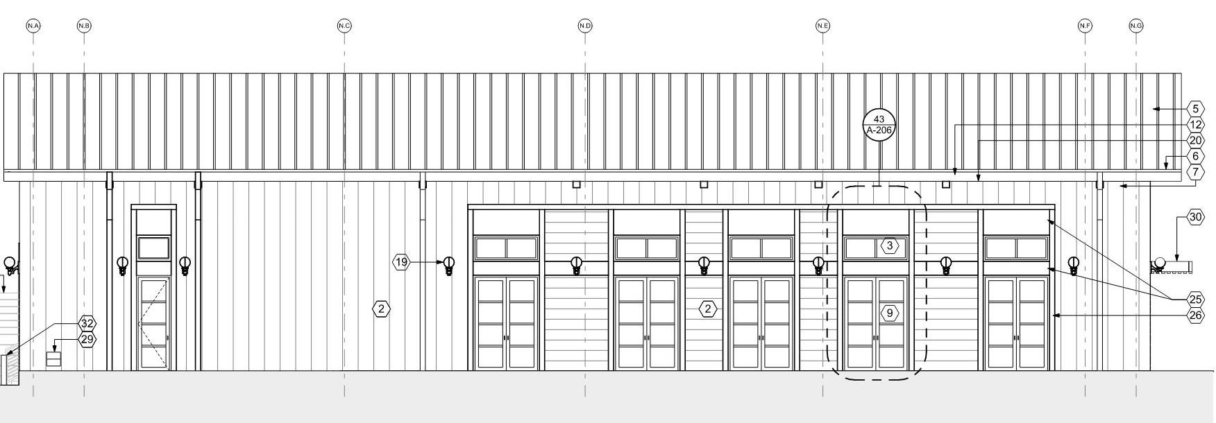
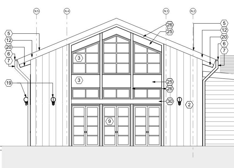
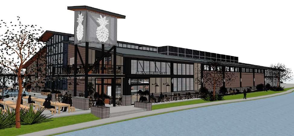
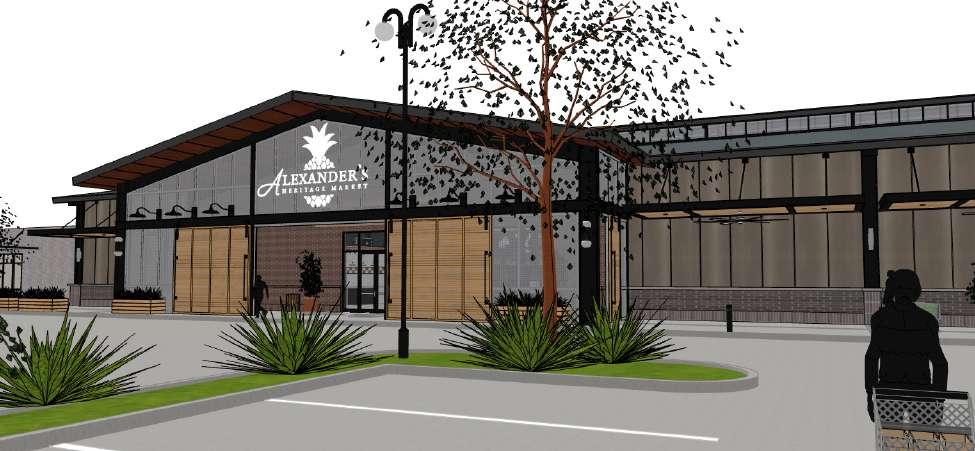
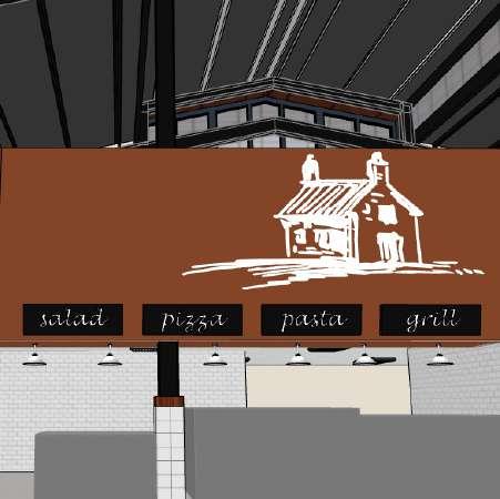
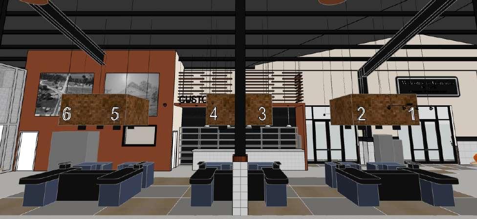
Louisiana-based grocery chain Alexander’s Market approached MetroStudio to design a new store as part of a planned mixeduse development in Gonzales, LA. Once a rural area, Gonzales is rapidly expanding and transforming into a bridging suburb between New Orleans and Baton Rouge. The design team emphasized the need for a stand-out building to distinguish Alexander’s from other stores in the area. Likewise, the development group expressed their desire for this location to compete with specialty grocers such as Whole Foods, HEB, and Trader Joe’s. With this in mind, our team developed a series of schemes which married the formal language and material palette of rural vernacular architecture with the programming elements of contemporary nationwide grocery chains. The final scheme, an adaptation of the monitor barn typology, makes use of large-scale exterior decals and murals to tie the market to the town of Gonzales. Clerestory windows in the monitor allow natural light to spread over interior elements including a wine bar, a sushi bar, and a cafe. Construction began in 2022.
2'-5 1/2" 26'-1 1/2" 21'-3 3/4" 26'-1 1/2" 5'-1 1/2" WP 10' 4'-9 3/4" 2'-6" 26'-2" 26'-2" 21'-6" 30'-9 3/4" 26'-2" 26'-2" 28'-10" 23'-4 3/4" 28'-2 3/4" 27'-2 3/4" 27'-2 3/4" 27'-2 3/4" 28'-2 3/4" 2'-5 1/2" 12'-6 1/2" 7'-4" 23'-9 1/4" 2'-1 3/4" 6'-11 3/4" 11'-5 3/4" 5'-6 3/4" 2'-9 1/2" 1'-1/2" 2'-4 3/4" 5 1/4" 10'-1 1/4" 5'-9" 6'-5" 4'-7 1/2" 16'-6 1/4" 27'-1/4" 18'-2 1/2" 43'-6 1/2" 9'-11 3/4" 2'-6 1/4" 2'-11 3/4" 107'-1 1/4" 57'-2" 4'-11 1/4" 1'-1" 23'-5 3/4" 6" 140'-7 1/2" 12'-6 1/2" 6'-8 1/2" 8'-10 3/4" 1'-5" 2'-8" 6'-5 3/4" 16'-1/4" 4'-9 1/2" 5'-4 1/4" 7" 4'-2 1/2" 24'-1/2" 1/4" 2'-8" 1'-5" 23'-7 1/2" 2'-1/4" 2'-4 3/4" 1'-3 3/4" 21'-5 3/4" 2 1/4" 6'-7 1/2" 19'-4 1/4" 20'-2 1/4" 7'-1/2" 8'-6" 18'-8 3/4" 17'-7 1/2" 1'-7" 11'-7 1/4" 6'-2 1/2" 12'-3 1/2" 8'-9" 22'-9 1/2" 3'-6" 6'-8 1/2" 22'-5 1/2" 14' 2'-6 1/2" 2'-3" 2'-3 3/4" 3'-1 1/2" 1'-4" 7 1/4" 1'-4" 2'-9" 4'-2" 2'-10 1/2" 2'-1 1/4" 14'-7 1/4" 23'-6" 9'-6" 135° 135° 135° 135° 135° 151° 125° CAFE DINING 017 MEN S R R 022 MANAGER 004 COUNT ROOM 005 CAMERA ROOM 006 BAKERY COOLER 007 BAKERY FREEZER 008 ONLINE FILLING AREA 009 BAKERY AREA 010 SUSHI PREP 011 ROTISSERIE DISPLAY 013 DELI GRAB & GO 012 SOUP KIOSK 014 KITCHEN 015 DRINKKIOSK 016 HALLWAY 018 BOH CLOSET 020 WOMEN S R R 021 DAIRY 023 SMOKED MEAT 024 FRESH MEAT 025 WAREHOUSE 026 GROCERY FREEZER 027 DAIRY COOLER 028 MEAT COOLER 029 MEAT PREP 030 MEAT FREEZER 031 FRYING ROOM 032 FROZEN SEAFOOD 033 PRODUCE PREP 034 PRODUCE COOLER 035 PRODUCE 036 JUICE 037 FLORAL 038 WINE TASTING 039 ENTRANCE 040 LOADING DOCK 041 OUTDOOR DINING 042 CURBSIDE PICKUP 043 3 3 2 2 4 4 5 5 6 6 7 7 8 8 9 9 10 10 D D F F G G H H C C E E 1 1 B B A A 6 1 6 1 7 1 7 1 7 2 7 2 8 1 8 1 1 1 1 1 1 2 1 2 F 1 F 1 G 1 G 1 H 1 H 1 5'-1" 8'-3 1/4" 7'-8 1/2" 6'-1/4" 24'-4" 105'-6 1/2" 46'-11 1/2" 4'-7 1/4" 16'-6 1/4" 88'-10 1/4" 4'-9 3/4" 7'-4" 7'-4 1/4" 35'-11 3/4" 48'-4 1/2" 7'-1" 22'-10 1/4" 4'-6 1/4" 94'-6 3/4" 16'-2 1/2" 9'-5 1/2" 9'-11 1/4" 7'-3 1/2" 1'-6 1/2" 28'-6 1/4" 42'-6" 8'-2 1/2" 11'-7" 25'-11" 39'-9 1/2" 42'-2 1/4" 10'-6 1/2" 3' 33'-11 1/2" 11'-10 1/2" 16'-3 1/4" 7'-10 3/4" 39'-11 1/4" 11'-11 1/2" 14'-2 1/2" 9'-4" 10'-10 1/2" 6'-5 3/4" 1'-6 1/2" 1/4" 20'-9" 110'-6 3/4" 6'-10 1/4" 1/4" 25'-10" 9'-1" 97'-1" 6'-2" 3' 6'-8 3/4" 8'-5 1/4" 20'-10" 1'-7 1/2" 16'-10 1/2" 34'-10 3/4" 20'-6 3/4" 14'-9 3/4" 159'-5 1/4" 52'-3 3/4" 8'-3/4" 1'-11" 12' 6'-10 1/4" 151° MAIN SALES FLOOR 001 CHECKOUT 002 CUSTOMER SERVICE 003 DIMENSION PLAN GENERAL GENERAL NOTES 1 ALL DIMENSIONS SHOWN THE FINISHED FACE OF WALL PLANS AND PARTITION TYPES INFORMATION 2 CONTRACTOR SHALL CONTACT IMMEDIATELY IF ANY DIMENSIONAL ARISE 3 DRAWINGS SHALL NOT BE DIMENSIONS ARE NEEDED THAT CONTRACTOR SHALL ACQUIRE 4 REFER TO INTERIOR ELEVATIONS HEIGHTS FIXTURE CENTERLINES 5 REFER TO GENERAL ACCESSIBILTY FIXTURE HEIGHTS PER ADAAG 0 8 16 24 SCALE: 3 32" = 1 -0 25 1st FLOOR DIMENSIONED PLAN
interior elevations
INTERIOR ELEVATION KEYNOTES 1 2 3 4 5 6 7 11 8 9 10 12 13 14 17 18 19 20 21 16 15 22 23 24 CUSTOM SIGNAGE SEE SIGNAGE PACKAGE FOR MORE INFO SCHEDULED BASE SEE FINISH SCHEDULE FOR MORE INFO TL-2 SEE FINISH LEGEND STRUCTURAL COLUMN SEE PLANS FOR MORE INFO WD-2 WALL PANEL SEE FINISH LEGEND PAINTED GYP , TYP WD-1 WALL PANEL SEE FINISH LEGEND DECORATIVE LIGHT FIXTURE SEE RCPS FOR MORE INFO DOOR SEE PLANS AND SCHEDULE FOR MORE INFO HVAC EQUIPMENT SEE MECHANICAL RECLAIMED WOOD PLANKS SUSPENDED ON METAL RODS SEE DETAILS CUSTOM LARGE PRINT PHOTOGRAPH SEE SIGNAGE PACKAGE FOR MORE INFO WINDOW SEE PLANS AND SCHEDULE FOR MORE INFO METAL CABLE RAILING SEE DETAILS FOR MORE INFO CABLE HUNG GYP BD CEILING AND SOFFIT SEE RCPS FOR MORE INFO TL-3 SEE FINISH LEGEND CUSTOM MILLWORK UNIT WITH CT-1 COUNTERTOP SEE MILLWORK DETAILS FOR MORE INFO CEILING ABOVE PAINTED WOOD PLANKS SUSPENDED ON METAL RODS SEE DETAILS STEEL STRUCTURE STAIR WITH WOOD TREADS SEE DETAILS FOR MORE INFO TL-1 SEE FINISH LEGEND SUSPENDED ACOUSTICAL PANELS SEE RCPS FOR MORE INFO FLOATING COUNTERTOP CT-1 SEE DETAILS PLUMBING FIXTURE SEE PLANS AND SCHEDULE 25 26 VERTICAL BRICK PAVERS BR-3 SEE FINISH LEGEND PERFORATED METAL 27 28 PAINTED GYP AND HARDIE TRIM NOT USED 29 SHADED AREA INDICATES EQUIPMENT PROVIDED BY OTHERS 30 31 FRP-X SEE FINISH LEGEND 2X6 BATTENS WD-3 32 WALLCOVERING WC-1 SEE FINISH LEGEND 33 FULLY WELDED 4X4 TS FRAME TYP 34 ALL STEEL TO BE PAINTED SEE SPECIFICATION FOR PAINT INFORMATION 35 1 2" BASE PLATES W HILTI HY 150 EPOXY ANCHORS TYP 36 BLACK ANODIZED FASTENERS @ STEEL FRAME 37 ST-1 SEE FINISH SCHEDULE 38 1X WOOD TRIM SEE WALL SECTIONS GENERAL NOTES 39 40 STONE COPING WATER TABLE RUNNING BOND MASONRY VENEER - BR-1 SEE FINISH LEGEND 41 SOLDIER COURSE MASNORY VENEER - BR-2; SEE FINISH LEGEND 42 METAL PANEL RAIN SCREEN - MP-1 SEE FINISH LEGEND 1 PREPARE ALL SUBSTRATES FOR FINISHES AS REQUIRED BY FINISH MFR 2 ALL INTERIOR STEEL / METAL TO BE PAINTED WITH DIRECT TO METAL (DTM) PAINT CLEAN AND PREPARE ALL SURFACES PER COATING MFR COLORS TO BE SELECTED FROM FULL RANGE 3 COLORS OF MATERIALS NOT YET SELECTED SHALL BE PRICED PER FULL RANGE OF MATERIALS SELECTIONS 4 MOISTURE PRONE AREAS SHALL RECIEVE MOISURE REISTANT GYPSUM BOARD 5 WALLS TO RECIEVE TILE AS A FINISH SURFACE SHALL INCORPERATE CONCRETE BACKER BOARD AS A SUBSTRATE 6 REFER TO INTERIOR SECTIONS FOR ADDITIONAL INFORMATION 43 3 WIDE BY 4 TALL METAL ACCESS PANEL PAINTED TO MATCH ADJACENT GYPSUM BOARD 3'-6" 18'-4" 7'-9" 21 21 29 3'-6" 9' 1' 18'-4" 7'-6" TYP 8 21 6 9 29 15 29 3'-6" 1' 18'-4" 6 8 15 3'-6" 7'-6" 1' TYP TYP TYP 6 1 5 1 6 10 11 21 6 15 7 29 5' 6" 9' 8" 17 16 7 0 2 4 8 SCALE: 1 4" = 1 -0 22 SEAFOOD COOLER ELEVATION 0 2 4 8 SCALE: 1 4" = 1 -0 17 BUTCHER COUNTER ELEVATION SCALE 12 MEAT 0 2 4 8 SCALE: 1/4" = 1 -0" 24 MEAT COOLER ELEVATION INTERIOR ELEVATION KEYNOTES 1 2 3 4 5 6 7 11 8 9 10 12 13 14 17 18 19 20 21 16 15 22 23 24 CUSTOM SIGNAGE SEE SIGNAGE PACKAGE FOR MORE INFO SCHEDULED BASE SEE FINISH SCHEDULE FOR MORE INFO TL-2 SEE FINISH LEGEND STRUCTURAL COLUMN SEE PLANS FOR MORE INFO WD-2 WALL PANEL SEE FINISH LEGEND PAINTED GYP TYP WD-1 WALL PANEL SEE FINISH LEGEND DECORATIVE LIGHT FIXTURE SEE RCPS FOR MORE INFO DOOR SEE PLANS AND SCHEDULE FOR MORE INFO HVAC EQUIPMENT SEE MECHANICAL RECLAIMED WOOD PLANKS SUSPENDED ON METAL RODS SEE DETAILS CUSTOM LARGE PRINT PHOTOGRAPH, SEE SIGNAGE PACKAGE FOR MORE INFO WINDOW SEE PLANS AND SCHEDULE FOR MORE INFO METAL CABLE RAILING SEE DETAILS FOR MORE INFO CABLE HUNG GYP BD CEILING AND SOFFIT SEE RCPS FOR MORE INFO TL-3 SEE FINISH LEGEND CUSTOM MILLWORK UNIT WITH CT-1 COUNTERTOP SEE MILLWORK DETAILS FOR MORE INFO CEILING ABOVE PAINTED WOOD PLANKS SUSPENDED ON METAL RODS SEE DETAILS STEEL STRUCTURE STAIR WITH WOOD TREADS SEE DETAILS FOR MORE INFO TL-1 SEE FINISH LEGEND SUSPENDED ACOUSTICAL PANELS SEE RCPS FOR MORE INFO FLOATING COUNTERTOP CT-1 SEE DETAILS PLUMBING FIXTURE, SEE PLANS AND SCHEDULE 25 26 VERTICAL BRICK PAVERS BR-3 SEE FINISH LEGEND PERFORATED METAL 27 28 PAINTED GYP AND HARDIE TRIM NOT USED 29 SHADED AREA INDICATES EQUIPMENT PROVIDED BY OTHERS 30 31 FRP-X SEE FINISH LEGEND 2X6 BATTENS WD-3 32 WALLCOVERING WC-1 SEE FINISH LEGEND 33 FULLY WELDED 4X4 TS FRAME TYP 34 ALL STEEL TO BE PAINTED; SEE SPECIFICATION FOR PAINT INFORMATION 35 1/2" BASE PLATES W/ HILTI HY 150 EPOXY ANCHORS TYP 36 BLACK ANODIZED FASTENERS @ STEEL FRAME 37 ST-1 SEE FINISH SCHEDULE 38 1X WOOD TRIM SEE WALL SECTIONS 39 40 STONE COPING WATER TABLE RUNNING BOND MASONRY VENEER - BR-1; SEE FINISH LEGEND 41 SOLDIER COURSE MASNORY VENEER - BR-2 SEE FINISH LEGEND 42 METAL PANEL RAIN SCREEN - MP-1 SEE FINISH LEGEND 43 3 WIDE BY 4 TALL METAL ACCESS PANEL PAINTED TO MATCH ADJACENT GYPSUM BOARD 25 -421 21 3'-6" 9' 1' 18'-4" 8" 7'-6" 10 A-422 TYP 5 1 6 7 8 21 6 9 29 15 29 3'-6" 7'-6" 1' 18'-4" TYP 6 1 1 5 1 1 21 6 6 8 7 15 29 29 1' TYP TYP TYP 6 1 5 1 10 11 21 6 15 29 5' 6" 9' 8" 20 A-423 25 A-423 TYP TYP TYP TYP 17 16 4 1 8 7 15 7 27 27 38 21 24 29 0 2 4 8 COOLER ELEVATION 0 2 4 8 SCALE: 1/4" = 1 -0 17 BUTCHER COUNTER ELEVATION 0 2 4 8 SCALE 1/4" = 1 -0 12 MEAT COOLER ELEVATION 0 2 4 8 SCALE: 1/4" = 1 -0 24 MEAT COOLER ELEVATION 0 2 4 8 SCALE: 1/4" = 1 -0 14 FLORAL AND PRODUCE ELEVATION ELEVATION KEYNOTES 13 14 17 18 19 20 21 16 15 22 23 24 SIGNAGE SEE SIGNAGE PACKAGE FOR BASE SEE FINISH SCHEDULE FOR FINISH LEGEND COLUMN SEE PLANS FOR MORE PANEL SEE FINISH LEGEND TYP PANEL SEE FINISH LEGEND LIGHT FIXTURE SEE RCPS FOR PLANS AND SCHEDULE FOR MORE EQUIPMENT SEE MECHANICAL WOOD PLANKS SUSPENDED ON SEE DETAILS LARGE PRINT PHOTOGRAPH, SEE PACKAGE FOR MORE INFO WINDOW SEE PLANS AND SCHEDULE FOR MORE INFO METAL CABLE RAILING SEE DETAILS FOR MORE INFO CABLE HUNG GYP BD CEILING AND SOFFIT SEE RCPS FOR MORE INFO TL-3 SEE FINISH LEGEND CUSTOM MILLWORK UNIT WITH CT-1 COUNTERTOP SEE MILLWORK DETAILS FOR MORE INFO CEILING ABOVE PAINTED WOOD PLANKS SUSPENDED ON METAL RODS SEE DETAILS STEEL STRUCTURE STAIR WITH WOOD TREADS SEE DETAILS FOR MORE INFO TL-1 SEE FINISH LEGEND SUSPENDED ACOUSTICAL PANELS SEE RCPS FOR MORE INFO FLOATING COUNTERTOP CT-1 SEE DETAILS PLUMBING FIXTURE, SEE PLANS AND SCHEDULE 25 26 VERTICAL BRICK PAVERS BR-3 SEE FINISH LEGEND PERFORATED METAL 27 28 PAINTED GYP AND HARDIE TRIM NOT USED 29 SHADED AREA INDICATES EQUIPMENT PROVIDED BY OTHERS 30 31 FRP-X SEE FINISH LEGEND 2X6 BATTENS WD-3 32 WALLCOVERING WC-1 SEE FINISH LEGEND 33 FULLY WELDED 4X4 TS FRAME TYP 34 ALL STEEL TO BE PAINTED; SEE SPECIFICATION FOR PAINT INFORMATION 35 1/2" BASE PLATES W/ HILTI HY 150 EPOXY ANCHORS TYP 36 BLACK ANODIZED FASTENERS @ STEEL FRAME 37 ST-1 SEE FINISH SCHEDULE 38 1X WOOD TRIM SEE WALL SECTIONS 39 40 STONE COPING WATER TABLE RUNNING BOND MASONRY VENEER - BR-1; SEE FINISH LEGEND 41 SOLDIER COURSE MASNORY VENEER - BR-2 SEE FINISH LEGEND 42 METAL PANEL RAIN SCREEN - MP-1 SEE FINISH LEGEND 43 3 WIDE BY 4 TALL METAL ACCESS PANEL PAINTED TO MATCH ADJACENT GYPSUM BOARD 3'-6" 9' 1' 18'-4" 8" 7'-6" 10 A-422 TYP 5 1 6 7 8 21 6 9 29 15 29 3'-6" 7'-6" 1' 18'-4" TYP 6 1 1 5 1 1 21 6 6 8 7 15 29 29 1' TYP TYP TYP 6 1 11 21 6 15 29 5' 6" 9' 8" 20 A-423 25 A-423 TYP TYP TYP TYP TYP TYP 17 16 4 1 8 7 15 4 38 7 27 27 38 21 24 8 29 29 8 ELEVATION 0 2 4 8 SCALE: 1/4" = 1 -0 17 BUTCHER COUNTER ELEVATION 0 2 4 8 SCALE 1/4" = 1 -0 12 MEAT COOLER ELEVATION 0 2 4 8 SCALE: 1/4" = 1 -0 24 MEAT COOLER ELEVATION 0 2 4 8 SCALE: 1/4" = 1 -0 14 FLORAL AND PRODUCE ELEVATION 3'-6" 18'-4" 7'-9" 25 A-421 1 21 21 4 6 29 3'-6" 9' 1' 18'-4" 8" 7'-6" 10 A-422 TYP 5 1 6 7 8 21 6 9 29 15 29 3'-6" 7'-6" 1' 18'-4" 6 1 1 5 6 8 15 29 3'-6" 7'-6" 1' TYP TYP TYP 6 1 5 1 6 10 11 21 6 15 7 29 5' 6" 9' 8" 25 A-423 TYP TYP 17 16 4 1 8 7 15 38 0 2 4 8 SCALE: 1/4" = 1 -0 22 SEAFOOD COOLER ELEVATION 0 2 4 8 SCALE: 1/4" = 1 -0 17 BUTCHER COUNTER ELEVATION SCALE: 1/4" = 1 -0 12 MEAT COOLER 0 2 4 8 SCALE: 1 4" = 1 -0" 24 MEAT COOLER ELEVATION 14 AREVISION ISSUE # SHEET TITLE: THESE DOCUMENTS UNDER MY CLOSE PERSONAL COMPLY WITH ALL CITY PROJECT # #Pln SEAL CONSULTANTS INTERIOR CONCEPTUAL PLANS 1 STORE EQUIPMENT 2 LRK REVIEW 3 ISSUED FOR 4 STRUCTURAL ENGINEER EHC ENGINEERING 643 MAGAZINE NEW ORLEANS 504 372 1047 MEP ADG ENGINEERING 3071 TEDDY DRIVE BATON ROUGE 225 293 9474 EQUIPMENT DART COMMERCIAL 8600 ANSELMO BATON ROUGE 888 607 0063 ISSUED FOR PERMITTING 5 ISSUED FOR MARSHAL 6 415 St Gonzales ALEXANDER HERITAGE Desktop 6501 Spanish Fort 504 283 SEE PLANS AND SCHEDULE FOR MORE CABLE RAILING SEE DETAILS FOR MORE HUNG GYP BD CEILING AND SOFFIT SEE MORE INFO FINISH LEGEND MILLWORK UNIT WITH CT-1 COUNTERTOP MILLWORK DETAILS FOR MORE INFO ABOVE WOOD PLANKS SUSPENDED ON METAL DETAILS STRUCTURE STAIR WITH WOOD TREADS DETAILS FOR MORE INFO FINISH LEGEND SUSPENDED ACOUSTICAL PANELS SEE RCPS INFO COUNTERTOP CT-1 SEE DETAILS FIXTURE, SEE PLANS AND SCHEDULE 25 26 VERTICAL BRICK PAVERS BR-3 SEE FINISH LEGEND PERFORATED METAL 27 28 PAINTED GYP AND HARDIE TRIM NOT USED 29 SHADED AREA INDICATES EQUIPMENT PROVIDED BY OTHERS 30 31 FRP-X SEE FINISH LEGEND 2X6 BATTENS WD-3 32 WALLCOVERING WC-1 SEE FINISH LEGEND 33 FULLY WELDED 4X4 TS FRAME TYP 34 ALL STEEL TO BE PAINTED; SEE SPECIFICATION FOR PAINT INFORMATION 35 1/2" BASE PLATES W/ HILTI HY 150 EPOXY ANCHORS TYP 36 BLACK ANODIZED FASTENERS @ STEEL FRAME 37 ST-1 SEE FINISH SCHEDULE 38 1X WOOD TRIM SEE WALL SECTIONS 39 40 STONE COPING WATER TABLE RUNNING BOND MASONRY VENEER - BR-1; SEE FINISH LEGEND 41 SOLDIER COURSE MASNORY VENEER - BR-2 SEE FINISH LEGEND 42 METAL PANEL RAIN SCREEN - MP-1 SEE FINISH LEGEND 43 3 WIDE BY 4 TALL METAL ACCESS PANEL PAINTED TO MATCH ADJACENT GYPSUM BOARD 3'-6" 9' 1' 18'-4" 8" 7'-6" 10 A-422 TYP 1 6 8 21 6 29 15 29 3'-6" 7'-6" 1' 18'-4" TYP 6 1 1 5 1 1 21 6 6 8 7 15 29 29 1' 29 5' 6" 9' 8" 17'-8" 14'-2" 3'-6" 20 A-423 25 A-423 TYP TYP TYP TYP TYP TYP 17 16 4 1 8 7 15 4 38 7 1 27 27 38 21 24 8 29 29 ADDENDUM 7 95% ISSUED 8 0 2 4 8 BUTCHER COUNTER ELEVATION 0 2 4 8 SCALE 1/4" = 1 -0 12 MEAT COOLER ELEVATION 0 2 4 8 ELEVATION 0 2 4 8 SCALE: 1/4" = 1 -0 14 FLORAL AND PRODUCE ELEVATION
check out
freezer / cooler section building section
TYP. COOLER / FREEZER SECTION
25
VARIES, SEE PLANS FOR SIZES & LOCATIONS VARIES, SEE PLANS FOR SIZES & LOCATIONS VARIES, SEE PLANS FOR ADDITIONAL INFORMATION FINISHED FLOOR & BASE, SEE FINISH SCHEDULE 15# FELT SLIP SHEET TYP TWO (2) LAYERS 2 URETHANE RIGID INSULATION 4,000 PSI CONCRETE w/ 1 BAG (44 LB.) BEKAERT 30 45/50BL FIBERS MORTAR SETTING BED FLOOR TRACK BY MANUFACTURER, TYP MOISTURE RESISTANT GYPSUM BOARD ADJACENT TO FREEZER / COOLER WALL PANELS, TYP INTERIOR PARTITION SEE PLANS TYP WALK-IN COOLER WALK-IN FREEZER 7" 4" 3" CONCRETE SLAB SEE STRUCTURAL 2x REDWOOD SLEEPER THERMAL BREAK TOP OF WOOD TO BE FLUSH w/ TOP OF LEVEL SLAB TYP UNDER ALL COOLER / FREEZER WALLS 10 MIL VAPOR BARRIER INSULATED CEILING PANEL BY ARTIC TEMP INSTALLED PER MANUFACTURER SPEC'S & REQ S INSULATED WALL PANEL BY ARTIC TEMP INSTALLED PER MANUFACTURER SPEC'S & REQ S 0 6 12 18 SCALE: 1 1/2"= 1 -0
CONSULTANTS STRUCTURAL ENGINEER EHC ENGINEERING 643 MAGAZINE STREET NEW ORLEANS LA 504 372 1047 MEP ADG ENGINEERING 3071 TEDDY DRIVE BATON ROUGE LA 225 293 9474 EQUIPMENT DART COMMERCIAL 8600 ANSELMO LN BATON ROUGE LA 888 607 0063 415 St Christopher Gonzales ALEXANDER HERITAGE Desktop 6501 Spanish Fort Blvd 504 283 3685 // H G F D E C B A 27 28 28 28 28 20 19 20 24 9 9 29 4 31 20 20 ±0 1 1st FLOOR +10 2 MEZZANINE +20 3 TOWER +45 4 ROOF 15 A-412 20 A-413 EAVE HEIGHT 21 -0 PEAK HEIGHT 40 -9 1st FLOOR 0 -0 (9 -0" REF PER CSRS) MEZZ HEIGHT 12 -0 3 4 5 6 7 8 9 10 6 0 4 8 16 SCALE: 1 8" = 1 -0 22 SECTION
P.1
west elevation
Kim and Don’s House building section
floor plan
south elevation
building section
P.1 Kim and Don’s House - Waveland, MS
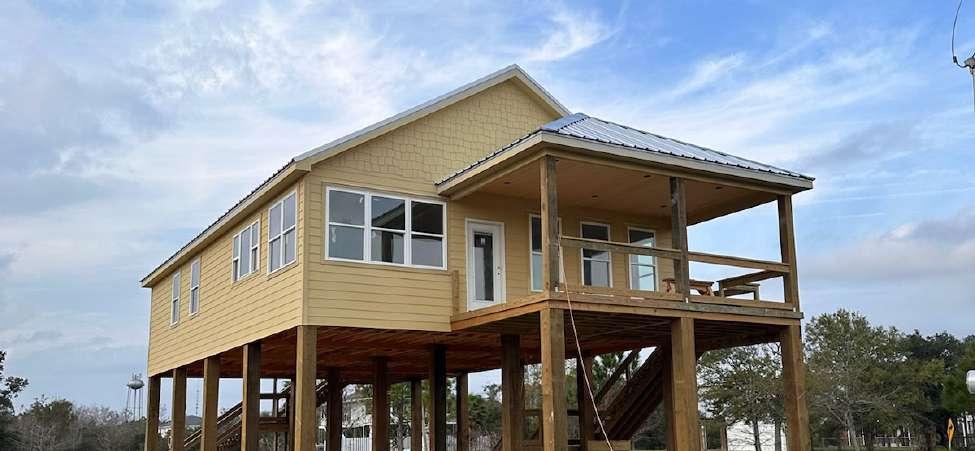
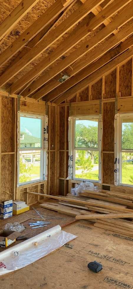
My parents have owned a large lot near the beach in Waveland, Mississippi since 2006. Over the course of 2021 and early 2022, I designed a four bedroom, two and a half bath house for them and provided them with an SD drawing set. The house has a ‘camp’ style floor plan, seeking to sleep as many people as possible, with a stark divide between the open living-eating space and the private sleeping quarters. The design is stylistically coastal and formally traditional with some contemporary detailing.
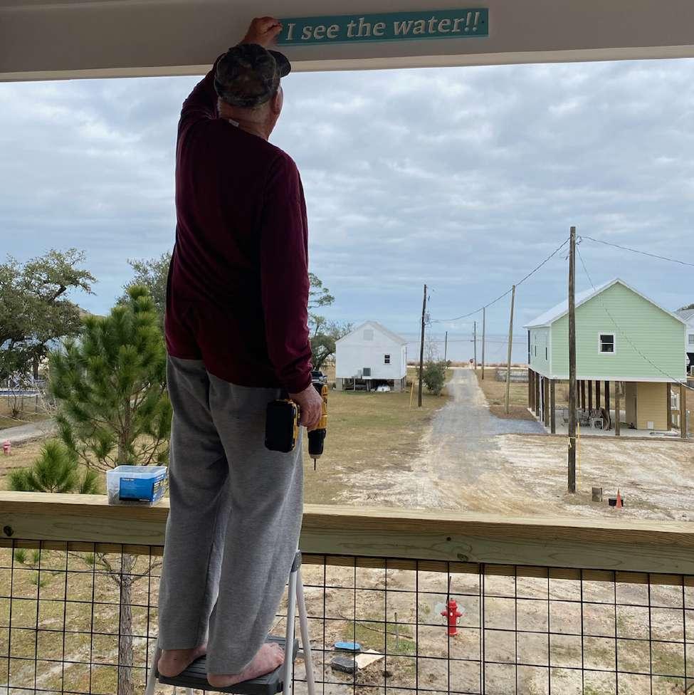
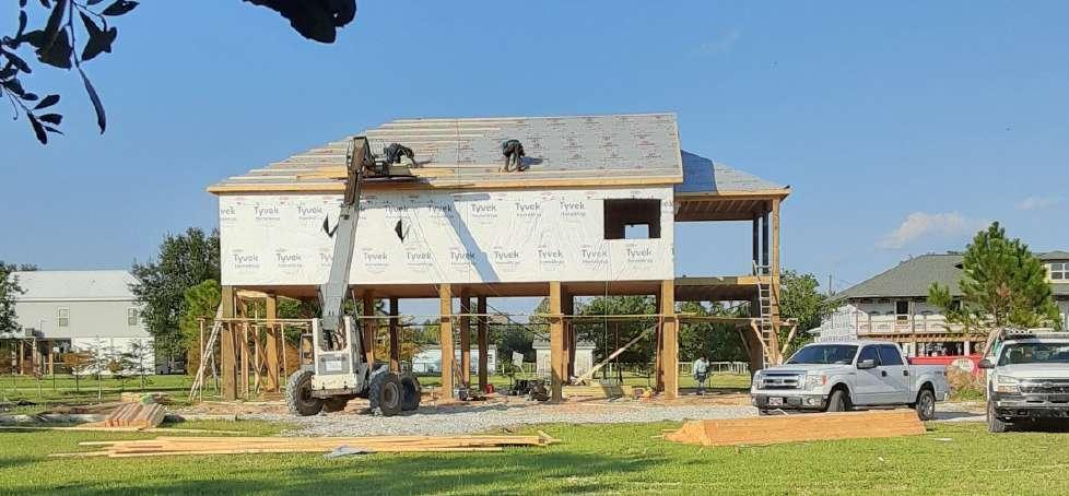
The house was not built as drawn. My parents are not wellversed in architecture, and we don’t quite have a relationship where I would be willing to fight them for design control. Their friend is a contractor; he took the SD drawings to a draftsman, got a permit, and built the house for them for cheap and fast, in the ways he knew how to build a house cheap and fast. While the house that was built is not quite the house I designed, I feel some ownership over it and some pride for having drawn it for my parents. It felt wrong to leave it out of this portfolio.
wall section
Don hanging his sign
 front porch
west face in progress

 painter at work
living room framing
S.1 Hostel
facade elevation
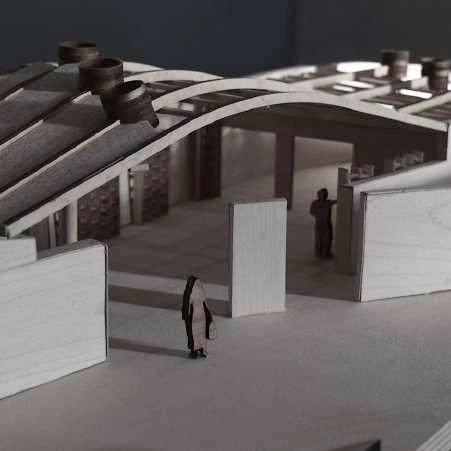
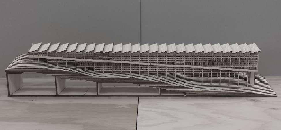
final model

plans (descending)

S.1 Hostel - Lake Tahoe, NV
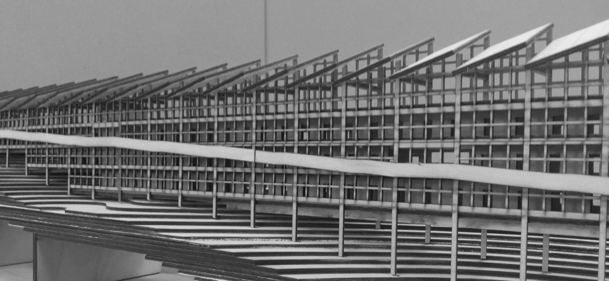
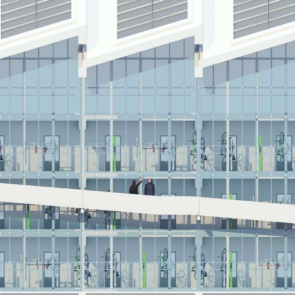
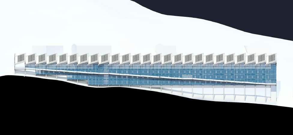
An ambitious program was the primary driver behind the form of the hostel: an energy efficient building housing a grand dining hall, sports equipment storage, and 100 rooms for up to 400 occupants. During the design process, the works of Luigi Snozzi and Aldo Rossi, particularly the Gallatarese Housing, became key conceptual influences. The project became about recognizing the beauty in repetition while acknowledging the human need for exceptions to the rules. The potential monotony of long hallways is alleviated by personalized storage areas which put each occupant’s preference of bike color, snowboard brand, helmet design, etc. on display. This circulatory showroom serves not only as a wayfinder but also as a variable in the building’s facade and a probable social spark between guests. Additionally, twenty-five near identical structural bays (of cross-laminated timber slabs and glu-lam columns) allow for a sawtooth roof ideal for harvesting solar energy. This project was completed in 2018 in Bruce Goodwin’s graduate comprehensive design studio at Tulane University.
corridor
southwest elevation
detailed wall section
photovoltaic panels
sawtooth roof
clerestory window
metal sheathing over CLT slab roof plane glulam bypass beams and columns

aluminium curtain wall attached with clips
concrete radiant floor heat recovery unit
electrical conduit tension rod supporting ramp
cold-rolled steel ramp water supply line waste pipe
radiant floor tubing
metal panels along back facade
crawlspace containing electrical and plumbing systems leads to mechanical room, height determined by 1% slope of waste pipe
steel plate connection terrain
concrete footing
isometric section 1/8”=1’

systems diagram top floor
S.2 Apartment


 east corner
courtyard section
S.2 Apartment - New Orleans, LA


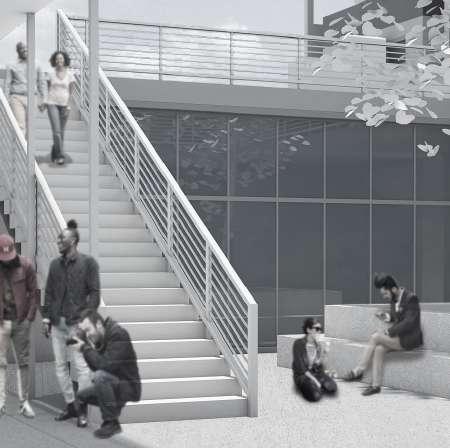
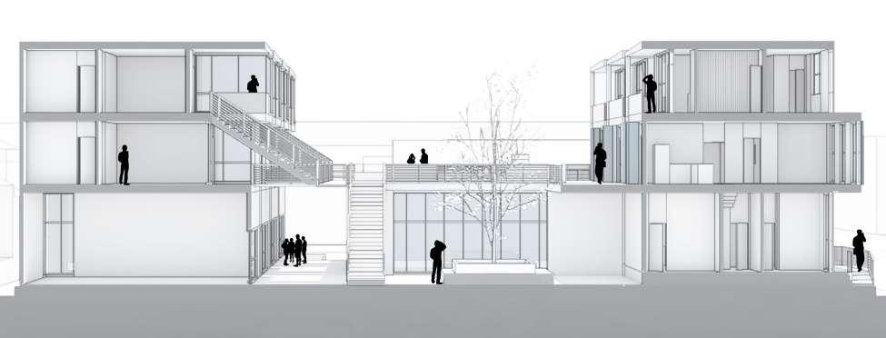
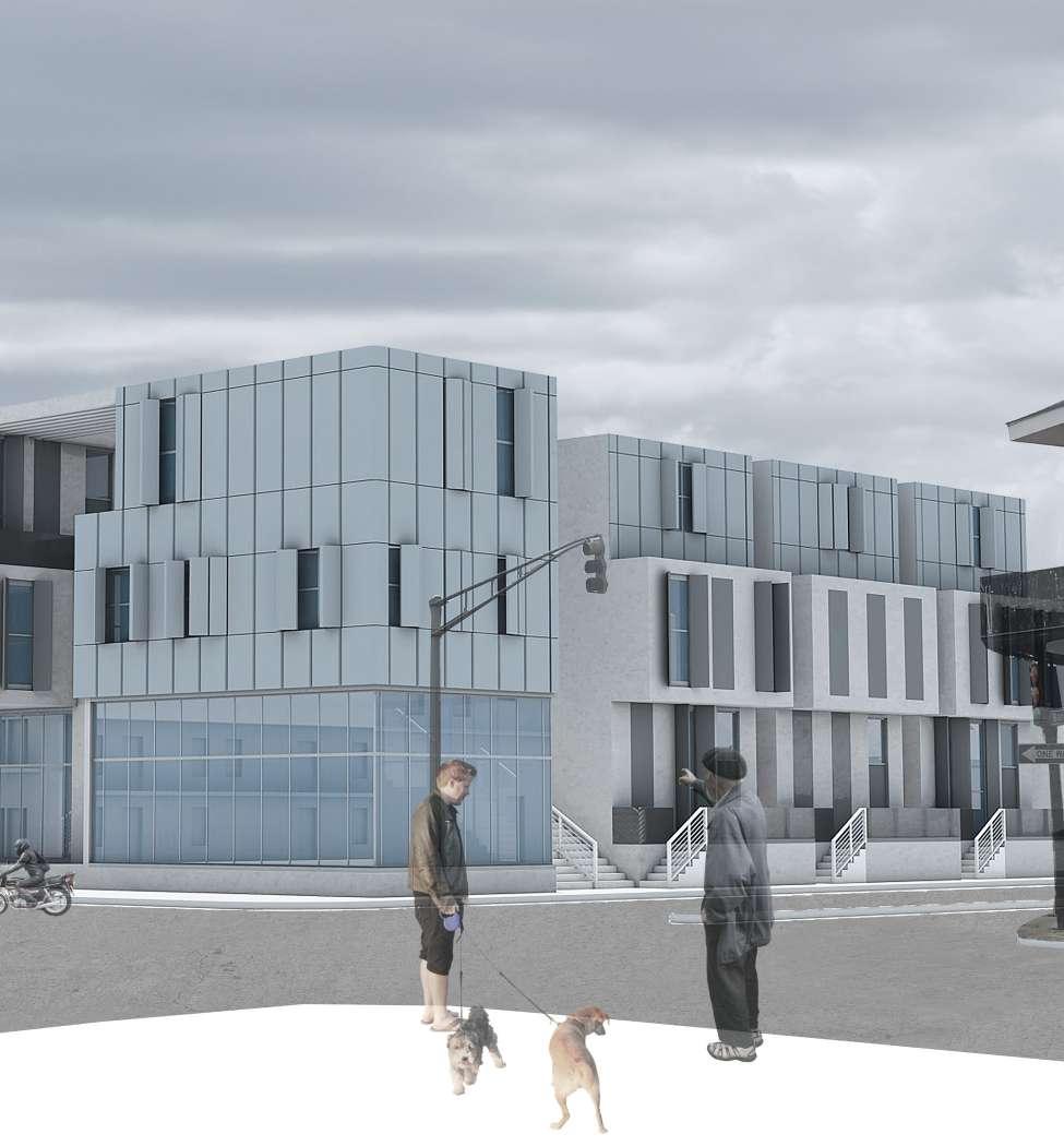
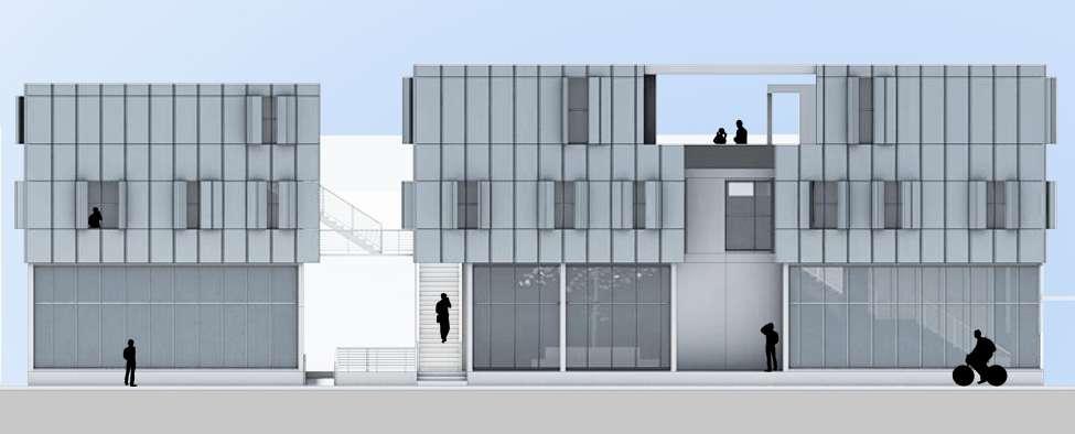
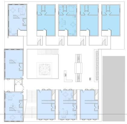
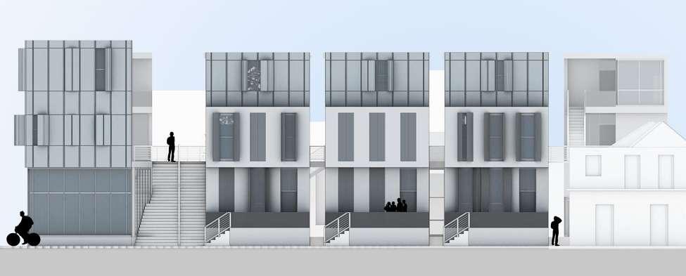
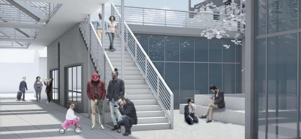
In New Orleans, the neighborhood is defined (both formally and socially) by exterior living spaces, the street, and the spatial proportions between these elements. Day-to-day connections between across the street neighbors and more eventful happenings such as street festivals and parades both become essential to the identity of the neighborhood. Sited in one of the most vibrant areas of New Orleans, the apartment adopts the structure-to-space proportions of the surrounding housing fabric. Long alleyways reveal glimpses of surrounding structures, and a large central courtyard plays the role of ‘street as gathering space.’ Each housing unit looks out over this space, giving a sense of community and ownership to each resident. Progression to each unit runs through this space, increasing the likelihood of chance interactions between neighbors. In addition to the residential units, the ground floor features a gym and five small commercial lease spaces. This project was completed in 2017 in Irene Keil’s graduate housing studio at Tulane University.
parti
courtyard
southeast elevation
third floor
second floor
ground floor unit isometrics
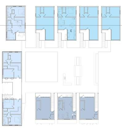



 final model
elevation
ground floor
northeast
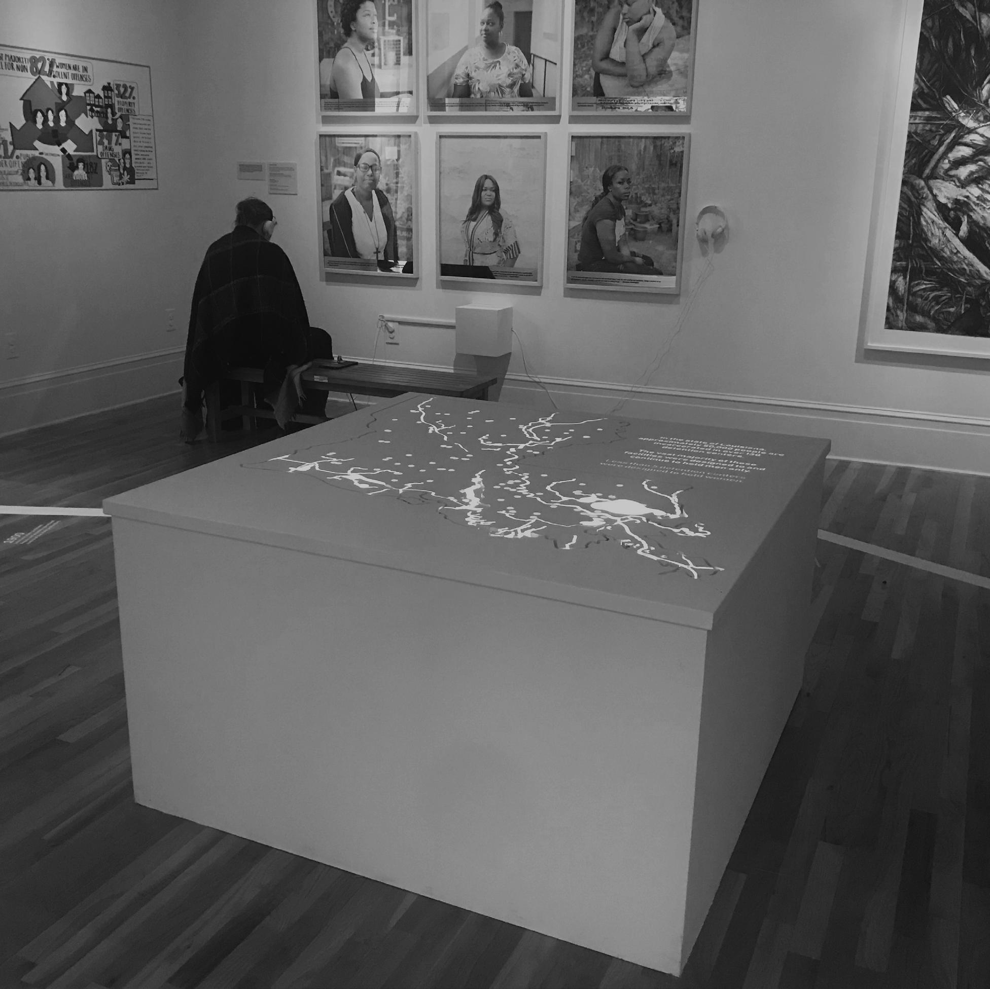
 installation on opening day
S.3 mixed media map projection
installation on opening day
installation on opening day
S.3 mixed media map projection
S.3 Mixed Media Map - New Orleans, LA
In 2019, the Newcomb Art Museum at Tulane University initiated a ten year plan to host three exhibitions highlighting the horrors of Louisiana’s unjust incarceration industry. The first, Persister, examines the plight of incarcerated and formerly incarcerated women. Museum administration gathered a team of architecture students to design parts of Persister including a map showing the dispersement of prisons and jails across the state. The team designed and executed an elevated map showing the state’s major bodies of water as negatives (CNC routed on campus). The map was then underlit, letting light shine through the lakes and rivers. A video projection suspended above placed markers at the location of each of the state’s incarceration centers and text about the state’s history of punishment on the map. A team of three (Casey Last, Hannah Bannister, and myself) initiated the project in an elective taught by Monica Ramirez Montegut and Laura Blereau at the Tulane School of Architecture in 2018. Persister opened in January of 2019.
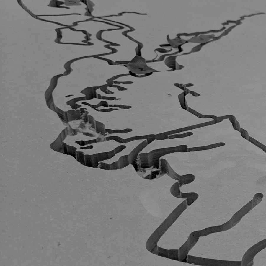

close up of map in process close up of finished map
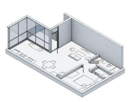
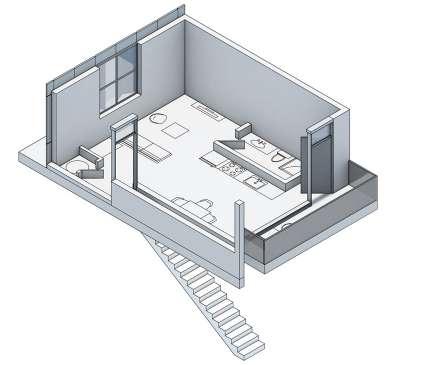
S.4.a URBANbuild14 prototype

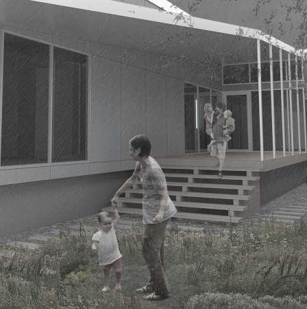
perspective | facing north
backyard/garden perspective | facing north
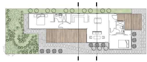
entry
plan
plan 1/4” = 1’ A B
street perspective | facing south A B
backyard/garden perspective | facing north
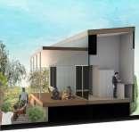
S.4 URBANbuild14 - New Orleans, LA
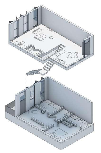
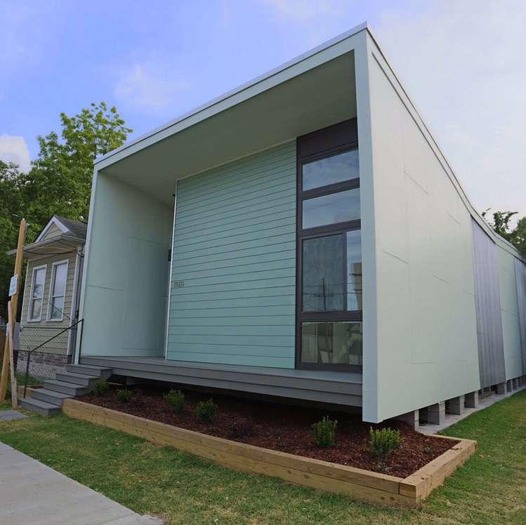
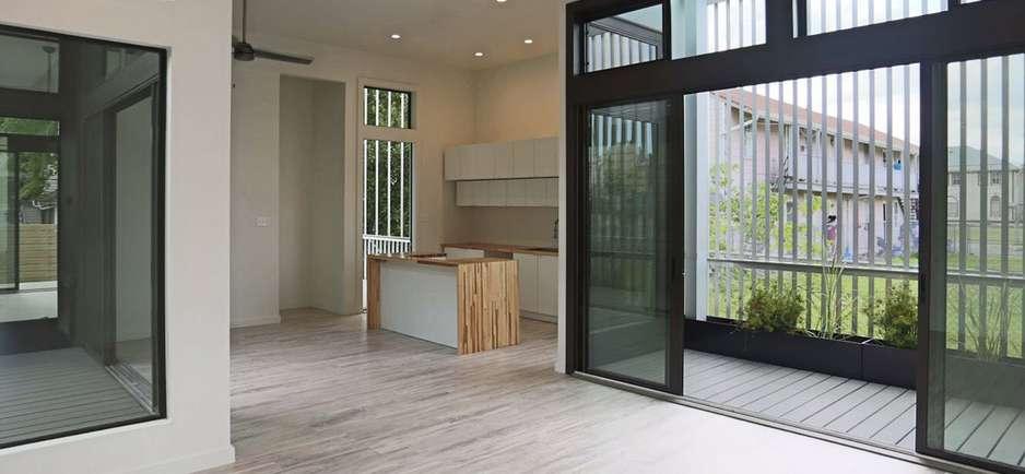
The program of the fourteenth entry in Tulane’s annual URBANbuild design studio asked participants to design a house with a growing family in mind. This idea of expansion and a garden strategy determined the form of this prototypical two bedroom home. A J-shaped primary roof covers every room of the house except the living room. This roof drains onto a secondary roof covering the living room and outdoor deck. The secondary roof drains into a lush garden in the back of the site, slowing down the flow of rainwater as it travels to the front of the site and enters the city’s drainage system. The backyard deck serves as an extension of the living room, but if needed, could be built out into a third bedroom for a larger family. This project was completed in 2018 with a partner, Katelin Morgan, in Byron Mouton’s URBANbuild studio at Tulane University. It was a runner-up in the selection of a scheme which would be built in the spring of 2019.

section B
kitchen section
backyard garden
S.4.b URBANbuild14 Construction Documents
front facade
section through guest bed, courtyard, kitchen, back porch

URBANbuild14 1920 HARMONY STREET, NEW ORLEANS, LOUISIANA 70115 SHEET NAME PROJECT PHASE TULANE SCHOOL OF ARCHITECTURE CONSTRUCTION DOCUMENTS BUILDING SECTION 5.1 2.1 3/8" = 1'-0" LONGITUDINAL SECTION A 1 NO: ISSUED FOR: DATE:
S.4 URBANbuild14 - New Orleans, LA
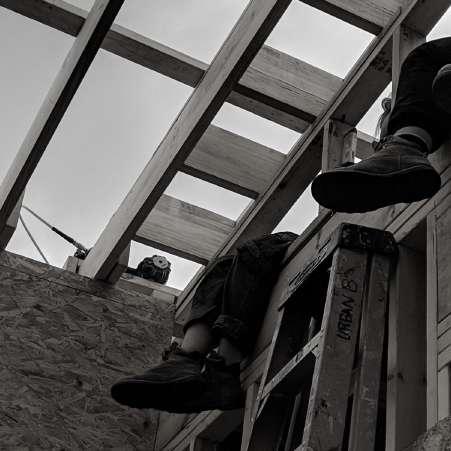
Once an URBANbuild scheme was selected for construction, four participating students were chosen to work on the permit documents for that scheme. I worked in Revit and AutoCAD on critical building sections and wall details while my three teammates, Ashley Libys, Bruna Aoki, and Katelin Morgan, completed the remainder of the drawings. During this six week period, the team not only drew the house but also made final design decisions based on budget, ease of construction, and spatial quality. As the four of us and eight other students began construction on the house in January of 2019, an extensive understanding of the house’s framing and organization helped us not only to execute the design as drawn but also to adapt and improvise when problems or opportunities arose. The project was completed in May of 2019 under the direction of Byron Mouton, Michael Mechtenberg, and Sara Allen Harper.
section through kitchen wall detail
section through master bed, courtyard, living room, entry
URBANbuild14 1920 HARMONY STREET, NEW ORLEANS, LOUISIANA 70115 CONSTRUCTION DOCUMENTS 5.2 BUILDING SECTION Issue Date NO: ISSUED FOR: DATE: 5.2 2.1 3/8" = 1'-0" LONGITUDINAL SECTION B 1 + STAIR DETAILS 5.2 2.1 3/4" = 1'-0" DETAIL STAIR PLAN 2 5.2 2.1 3/4" = 1'-0" DETAIL STAIR ELEVATION 3 URBANbuild14 1920 HARMONY STREET, NEW ORLEANS, LOUISIANA 70115 PROJECT PHASE B. MOUTON CONSTRUCTION DOCUMENTS 5.3 BUILDING SECTION 3/8" = 1'-0" CROSS SECTION A NO: ISSUED FOR: DATE: 5.3 2.1 3/8" = 1'-0" CROSS SECTION B 2
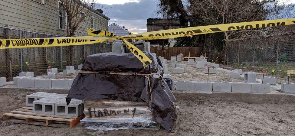
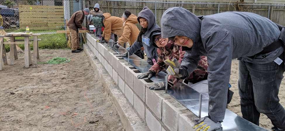
 floor framing
URBANbuild14 team
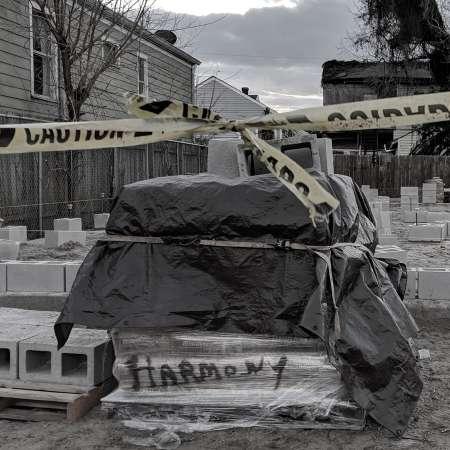
pier placement
S.4.c URBANbuild14 construction
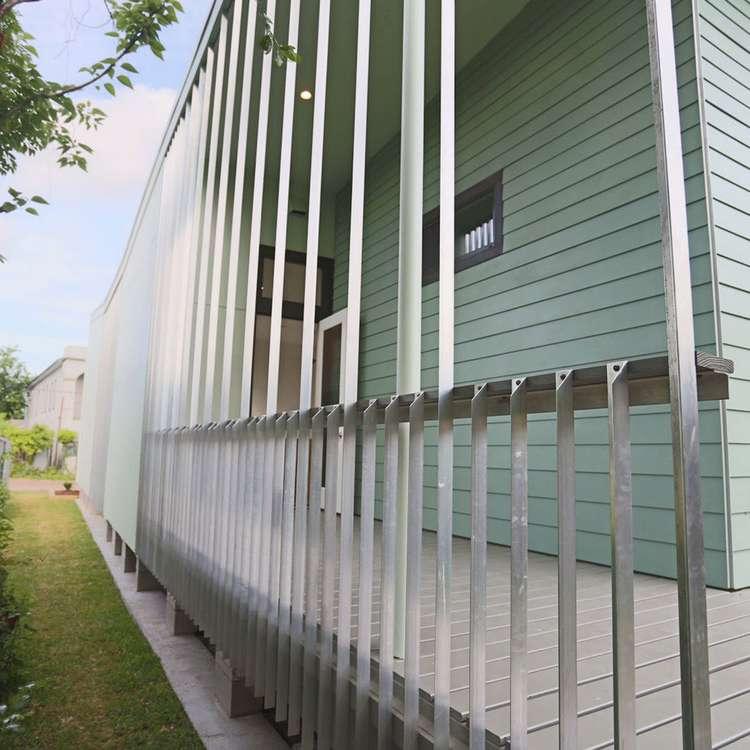
courtyard shade screen
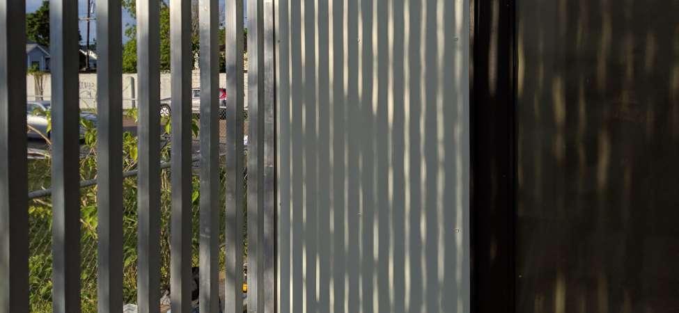
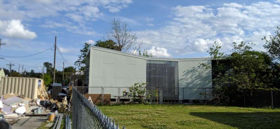
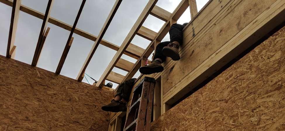 northwest elevation
a break


 pool and hotel balconies
W.2 Hotel Saint Vincent east elevation


 existing south facade
completed south facade


 front porch


 painter at work
living room framing


 east corner
courtyard section


 final model

 installation on opening day
S.3 mixed media map projection
installation on opening day
installation on opening day
S.3 mixed media map projection


 floor framing
URBANbuild14 team
pier placement
S.4.c URBANbuild14 construction


 northwest elevation
a break
 front facade
