
Vol. 10, Issue 1, pp: (14-20), Month: January - March 2022, Available at: www.researchpublish.com
A solar panel integrated three-level inverter with improvised performance using fuzzy logic controller
Anubhav Kumar Gupta1, Dr. Rajendra Murmu2 PG Student1, Assistant Professor2, Department of Electrical Engineering, BIT Sindri Dhanbad, IndiaAbstract: In this paper a three level inverter is introduced operated with FIS control for optimized operation for performance improvement connected to a solar panel. Three level or NPC are a family of multilevel power converters that are characterized by the use of clamping diodes for guaranteeing the proper voltage sharing across the power switches. A fuzzy logic controller with 49 rule base is introduced for the generation of reference signals compared to high frequency triangular waveforms for generation of pulses for the inverter. The PV module is modeled in MATLAB simulink environment connected to the inverter for renewable application. The output results are generated by graphs with respect to time.
Keywords: FIS (Fuzzy Interference System), NPC (Neutral Point Converter), PV (Photo Voltaic), MATLAB (Matrix Laboratory).
I. INTRODUCTION
MOST industrial processes need to increase efficiency and reduce production costs. This is achieved by increasing the size of installations and increasing the power of all electrical machines and equipment. This increase in power is reached in two ways: 1) by developing high-voltage semiconductors with voltage blocking capabilities of 3300, 4500, and 6500 V and2) by developing a multilevel inverter. Now, it is possible to directly connect the power converter to the mediumvoltage (MV) network. At low voltage, there is a single topology that dominates the market: the voltage-source two-level inverter. However, at medium and high voltages, the situation is completely different. A wide variety of topologies share the market and the applications of industrial MV drives [1, Fig. 1]. In effect, for high-power applications, it is possible to use direct converters (cyclo-converters) or indirect converters (with current or voltage dc link).
The continuous development of high-voltage insulated-gate bipolar transistors (IGBTs) and integrated-gate commutated thyristors (IGCTs) and the application of these power semiconductors in several multilevel voltage-source converter (VSC) topologies have led to a drastic increase of the nominal voltage and power ratings of self-commutated converters in recent years. Pulsewidth modulation (PWM) VSCs have replaced thyristor-based converters in a wide range of applications. This is largely due to substantial system advantages, such as increased availability due to ride through capability and/or a redundant converter design, drastically improved dynamic performance, extended operating range, reduced line harmonics, and an adjustable power factor at the point of common coupling.
Highly popular are the voltage-source multilevel inverters, which can be divided into three categories, according to their topology: neutral point clamped (NPC), flying capacitor (FLC), and cascade H-bridge [1], [2].Among the high-power converters shown in Fig. 1, the NPC inverter introduced 25 years ago is the most widely used in all types of industrial applications [3], [4], in the range of 2.3 to4.16 kV, with some applications up to 6 kV.
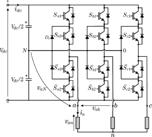
This paper presents a survey of the most relevant developments of this topology: concerning the modulation strategies and control methods, as well as the efficiency and use of power semiconductors. New topologies like the active NPC (ANPC) inverter are also discussed. Special attention is paid to the use of these inverters in non-regenerative and regenerative applications. Finally, the future of development in operation, control, and applications is highlighted. Fig.1 shows the power circuit of the three-level diode-clamped inverter. The clamping diode dc is used to connect the neutral point N to the midpoint of the transistor. This neutral N, generating an additional voltage level, yields the name “three-level inverter.”
International Journal of Electrical and Electronics Research ISSN 2348-6988 (online)
Page | 14 Research Publish Journals
International Journal of Electrical and Electronics Research ISSN 2348-6988 (online)
Vol. 10, Issue 1, pp: (14-20), Month: January - March 2022, Available at: www.researchpublish.com
Fig. 1: Neutral Point converter or three level inverter
In this paper, FLC is suggested to enhance the performance of three-level inverter as result to optimize the whole system performance. FLC is used to modify the magnitude of direct and quadrature (d-q) current and to optimize the angle of current. Finally, the power quality is increased based on proposed FLC.
II. WORKING PRINCIPLE OF NPC
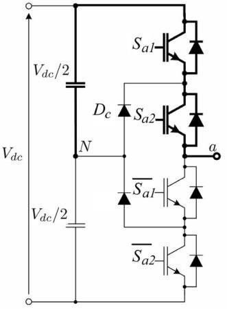
Fig. 2 shows the power circuit of the three-level diode-clamped inverter. The clamping diode dc is used to connect the neutral point N to the midpoint of the transistor. This neutral N, generating an additional voltage level, yields the name “three-level inverter.”
Fig. 2: Single leg operating state
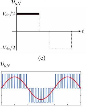
Fig. 3 shows the switching state that generates a positive voltage, at a load terminal. In this case, transitions Sa1 and Sa2 are switched ON, giving the value VaN = Vdc/2, where Syx isthe inverted signal of Syx (x =1, 2 and y = a, b, c), in order to avoid forbidden states, like short circuits. Table I shows the conduction state to be generated.
Fig. 3: Switching and output voltage generation
Page | 15 Research Publish Journals
International Journal of Electrical and Electronics Research ISSN 2348-6988 (online)
Vol. 10, Issue 1, pp: (14-20), Month: January - March 2022, Available at: www.researchpublish.com
Carrier-Based Three-Level PWM Modulation [5]–[9],: This highly popular method is based on the comparison of a sinusoidal reference υ∗ with two carriers υcr1 and υcr2.As shown in Fig. 4, the logic is very simple ∗
Today, the research on this modulation method is focused on the search for optimal switching sequences [5], operation at low modulation index [6], adaption to new topologies [7], [8], and reduction of common mode voltage [9].
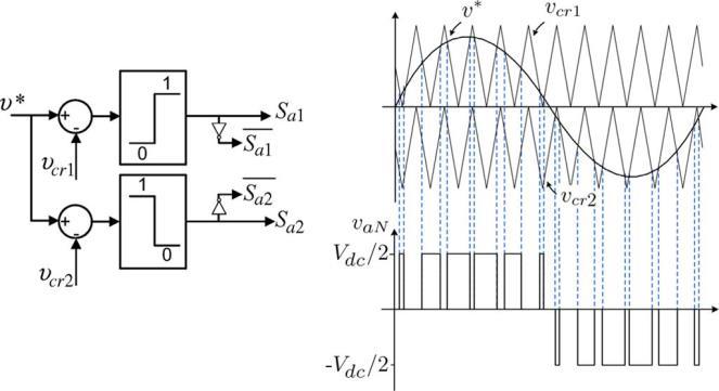
Fig. 4: Carrier based PWM modulation
III. FUZZY LOGIC CONTROL
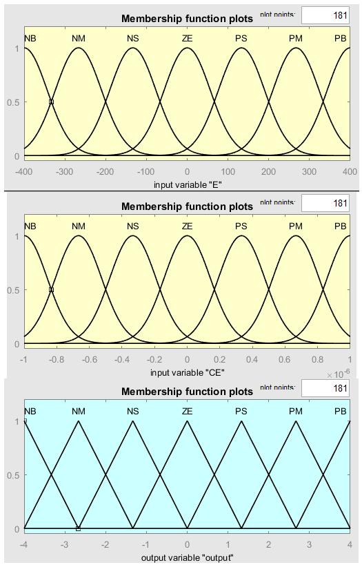
The FIS control structure is introduced with seven membership functions two input variables and two output variable with similar membership functions. The input variables are modeled with „gauss‟ type membership functions [14] and the output variable is modeled with „triangular‟ type membership functions. The FIS modeling is shown in figure 7 below.
Figure 5: FIS modeling
Page | 16 Research
Publish Journals
⇒ ∗ ⇒ ∗ ⇒
International Journal of Electrical and Electronics Research ISSN 2348-6988 (online)
Vol. 10, Issue 1, pp: (14-20), Month: January - March 2022, Available at: www.researchpublish.com
In the above figure ZE is zero region, PS is Positive Small region, PM is Positive medium region, PB is positive big region, NS is negative small region, NM is negative medium region, NB is negative big region. The first input variable is error (E) [15] set with a range -400 to 400, and second variable change in error (CE) is set with a range -1 to 1. The output variable is set with a range of -4 to 4. As per the membership functions the rule [15] is given as
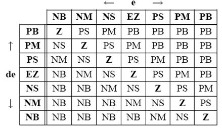
TABLE I: 49 rule base
With the above If-and-If-then rule base the PI controller is replaced with FIS module and the results are compared in the next section with graphical representation plotted with respect to time.
In this method, the three phase input voltage and current a,b,c are converted to direct and quadrature current d-q frame based on park transformation for more simplicity, and to convert from non-linear to linearity. The switching signal of three level inverters is determined based on the error between the reference current d-reference and actual current dactual. In this case, the FLC has two inputs, the first input is error and the second input is change of error with two outputs the magnitude of current and the angle.
IV. SIMULATION RESULTS
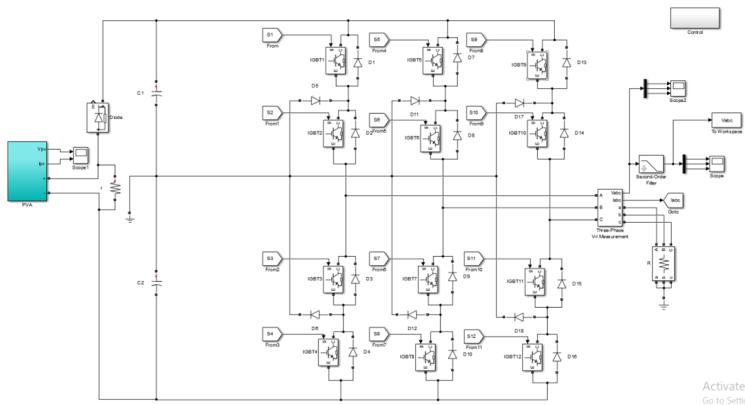
The below figure 6 is the simulation model of the proposed circuit topology with PV panel at the input.
Fig. 6: Proposed NPC with solar panel input
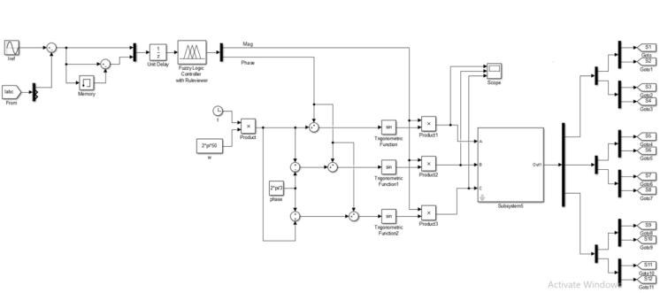
The figure 7 is the modeled control system of the proposed topology FIS control generating magnitude and phase angle of the reference signal. The reference signal is fed to carrier based PWM for generation of 12 pulses for the inverter.
Fig. 7: FIS control for the inverter
Page | 17 Research Publish
Journals
International Journal of Electrical and Electronics Research ISSN 2348-6988 (online)

Vol. 10, Issue 1, pp: (14-20), Month: January - March 2022, Available at: www.researchpublish.com
The rule base generation with given membership functions is shown in figure 8.
Fig. 8: Rule base generation for the FIS
Fig. 9: Output Line to ground voltages of a b c phases
The above are the voltage output of the inverter without LC filter with three level of voltages generated as per expected results. And the figure 10 is the filtered three phase voltages of the inverter.
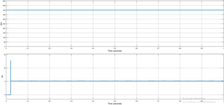
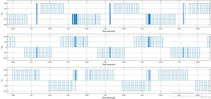
Fig. 10: Filtered voltage of abc phases
As per the given load the PV panel voltage and current waveforms are shown below in figure 11.
Fig. 11: PV panel characteristics

Page | 18 Research Publish
Journals
International Journal of Electrical and Electronics Research ISSN 2348-6988 (online)
Vol. 10, Issue 1, pp: (14-20), Month: January - March 2022, Available at: www.researchpublish.com
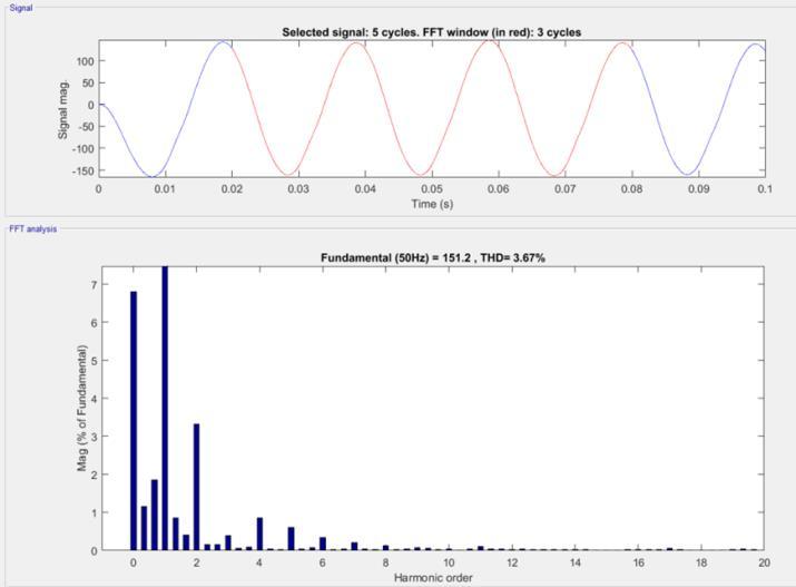
Fig. 12: THD of output voltage
The above is the THD analysis of the output voltage after filtering using LC filter carried out using FFT analysis tool.
V. CONCLUSION
It can be considered that the NPC inverter is a completely mature topology today, very well established in high-power applications.The problem of balance in the capacitor voltages, originally considered as a drawback of this topology, is definitely solved using redundant states. Classical carrier based pulsewidth modulation has been the preferred modulation techniques for operation with low switching frequency, as demanded by this topology. The field of application of NPC inverters is permanently growing due to their compactness, efficiency, and good performance. The THD of the output voltage is maintained at 3.67% which is below 5% as per the IEEE standard. All the results are generated by powergui toolbox with respect to time using Simpowersystem block sets.
REFERENCES
[1] D. Floricau, E. Floricau, and M. Dumitrescu, “Natural doubling of the apparent switching frequency using threelevel ANPC converter,” in Proc. ISNCC Conf. Rec., Lágow, Poland, Jun. 2008, pp. 1–6.
[2] C. Haederli, P. Ladoux, T. Meynard, G. Gateau, and A.-M. Lienhardt, “Neutral point control in multi level converters applying novel modulation schemes,” in Proc. IEEE Power Electron. Spec. Conf., Jun. 2006, pp. 1–8.
[3] P. Barbosa, P. Steimer, J. Steinke, M. Winkelnkemper, and N. Celanovic, “Active-neutral-point-clamped (ANPC) multilevel converter technology,” in Proc. IEEE Power Electron. Spec. Conf., Recife, Brasil, Jun. 2005, p. 10.
[4] M. Malinowski, S. Stynski, W. Kolomyjski, and M. P. Kazmierkowski, “Control of three-level PWM converter applied to variable-speed-type turbines,” IEEE Trans. Ind. Electron., vol. 56, no. 1, pp. 69–77, Jan. 2009.
[5] J. D. Barros and J. F. Silva, “Optimal predictive control of three-phase NPC multilevel converter for power quality applications,” IEEE Trans. Ind. Electron., vol. 55, no. 10, pp. 3670–3681, Oct. 2008.
[6] J. I. Leon, S. Vazquez, R. Portillo, L. G. Franquelo, J. M. Carrasco,P. W. Wheeler, and A. J. Watson, “Threedimensional feedforward space vector modulation applied to multilevel diode-clamped converters,” IEEE Trans. Ind. Electron., vol. 56, no. 1, pp. 101–109, Jan. 2009.
[7] J. Zaragoza, J. Pou, S. Ceballos, E. Robles, P. Ibaez, and J. L. Villate, “A comprehensive study of a hybrid modulation technique for the neutral-point-clamped converter,” IEEE Trans. Ind. Electron., vol. 56, no. 2, pp. 294–304, Feb. 2009.
[8] J. Zaragoza, J. Pou, S. Ceballos, E. Robles, C. Jaen, and M. Corbalan, “Voltage-balance compensator for a carrierbased modulation in the neutral-point-clamped converter,” IEEE Trans. Ind. Electron., vol. 56, no. 2, pp. 305–314, Feb. 2009.
[9] M. A. Perez, P. Cortes, and J. Rodriguez, “Predictive control algorithm technique for multilevel asymmetric cascaded H-bridge inverters,” IEEE Trans. Ind. Electron., vol. 55, no. 12, pp. 4354–4361, Dec. 2008.
Page | 19 Research Publish Journals
International Journal of Electrical and Electronics Research ISSN 2348-6988 (online) Vol. 10, Issue 1, pp: (14-20), Month: January - March 2022, Available at: www.researchpublish.com
[10] Guiying Liu; Shiping Su; Peng Peng,: “Intelligent Control and Application of All-function Active Power Filter”, IEEE , International Conference on Intelligent Computation Technology and Automation, 2008, p. 1078-1081.
[11] Kerrouche Soumia, Krim Fateh,: “Three-phase active power filter based on fuzzy logic controller”, International Journal of Sciences and techniques of automatic Control & Computer engineering, Volume 3,N°1, 2009, p. 942–955.
[12] Zhaoming Qian,: “Novel Control Scheme Based on Per-phase Reference Current Calculation for Hybrid Series Active Power Filter with Fundamental Current Bypass Channel in Unbalanced Conditions”, IEEE, 35th Annual Power Elecrronics Specialists Conference, 2004, p. 999–1002.
[13] J.M. Correa and al,: “A Fuzzy-Controlled Pulse Density Modulation Strategy for a Series Resonant Inverter with Wide Load Range”, Proceeding of the Conference on Power Electronics Specialists, PESC'03, Acapulco, Mexico 15 -19 June, 2003.
[14] A. Sayeed et al,: “Fuzzy controller for inverter fe d induction machines converter”, IEEE Trans. on Industrial Electronics, vol. 30, N° 1, 1994, p. 78- 84.
[15] C.Kannana, Nalin KantMohantyb, R.Selvarasuc “A new topology for cascaded H-bridge multilevel inverter with PI and Fuzzy control” Elsevier, Energy Procedia.vol. 117. Pp.917-926. 2017
Page | 20 Research Publish Journals