
Vol. 10, Issue 2, pp: (1-9), Month: April - June 2022, Available at: www.researchpublish.com
Behavior of Composite RC Slabs Made of New Slabs Added to Old Ones Using Shear Dowels
Hesham A. Haggag1 , Moustafa A. Osman2 , Mohamed I El- Shewy3
1Professor, Civil Eng. Dept., Helwan University, Cairo, Egypt
2Professor, Civil Eng. Dept., Helwan University, Cairo, Egypt
3Structural Engineer, Master of Civil Eng. Student, Helwan University, Cairo, Egypt
Abstract: Structural Strengthening maybe required for structures to accommodate above the design values. Moreover, the change of the building use may require increase in structure element capacity. On the other hand, structural capacity upgrade may be needed in case of structural element deterioration.
Concrete structures need to be strengthened for any of the following reasons:
- Load increase due to higher live loads, increased wheel loads, installations of heavy machinery, or vibrations.
- Damage to the structural parts due to aging of construction materials or fire damage, corrosion of the steel reinforcement and/or impact of vehicles.
- Improvement in suitability for use due to limitation of deflections, reduction of stress in steel reinforcement and/or reduction of crack widths.
- Modification of structural system due to the elimination of walls/columns and/or openings cut through slabs.
- Errors in planning or construction due to insufficient design dimensions and/or insufficient reinforcing steel.
Keywords: Structural Strengthening, Composite RC Slabs, building, structural capacity, heavy machinery.
I. INTRODUCTION
Recently, many types of strengthening slabs systems appeared using new technique of shear dowels. The use of shear dowels allows the optimization of cost and building period. The building types, which are using the slabs strengthening includes housing, hotels, shopping centers and office buildings …., etc.
There are many methods to improve the behavior of slabs to withstand extra load, such as using the shear dowels to repair and increase the slabs thickness.
Strengthening for slabs is very important and has many technology methods that leads to high-cost impact to meet our requirements, however, our study in this research is developing and demands for consumer simple method in order to meet the design requirements with less cost in reasonable time.
The trial will be done for variable thickness of slabs by some evaluation of test results considering the study of the shear flow of the 2 connected slabs intersection surface.
The problem of shear transfer in concrete structures arises when shearing forces are transmitted across a definite plane. The composite interface presents a potential weakness; they must be designed to have at least the same shear capacity of the adjoining parts. To achieve the composite action between old and new part, different types of shear connection between the two concrete surfaces may be used, such as rough surface connection, shear keyed connection, steel doweled shear connection and using of Epoxy binding materials.
International Journal of Engineering Research and Reviews ISSN 2348-697X (Online)
Page | 1 Research Publish Journals
International Journal of Engineering Research and Reviews ISSN 2348-697X (Online)
Vol. 10, Issue 2, pp: (1-9), Month: April - June 2022, Available at: www.researchpublish.com
One of the main factors affecting the strength of different shear connections is the slab thickness and location of the dowels on/below/above the Slab Centre line.
The experimental program contains testing of Three one way simply supported pre-slabs and one reference monolithic slab.
The tests on concrete slabs cast at different times. The effect of surface condition was considered to be well cleaned and filled by water in order to get the best results with smooth and trowelled interface with steel dowels, did not reach the monolithic stage.
The slab consists of a pre-cast R.C layer and an in-situ R.C topping layer.
The composite interface between steel and concrete or between two concrete layers is one of the difficulties in constructing an analytical model for composite reinforced concrete members.
II. SLABS SAMPLE
The purpose of this study is to investigate the behaviour of reinforced concrete one way slab after increasing the slab thickness by using shear dowels to connect the old slab with the new one from top of the slab. 4 No. of slabs will be examined:
Slab No. Slab layer No.
Slab layer Thk. (mm) Slab Dim. (mm) As/m Strengthening type (l) shape Ult. Load (Ton)
Max. Displac. (mm)
S1 S1-1 90 500X1750 5Y10 Shear Dowel 22 34.85 S1-2 90 500X1750 5Y10 S2 S2-1 100 500X1750 5Y10 Shear Dowel 18.85 22.94 S2-2 80 500X1750 5Y10
S3 S3-1 120 500X1750 5Y10 Shear Dowel 16.95 38.08 S3-2 60 500X1750 5Y10 CS CS 180 500X1750 5Y10 13.50 34.35
III. PREPARATION ONE-WAY SLAB SPECIMEN
Control Slab “CS’’ – 18cm Thk. :
A wooden scaffolding system used to keep the module of the Control slab in a dimension of 0.50X1.75X0.18m over a Rigid place. (Fig. 3-1)
Steel mesh of 2 layers Y10@200 prepared for the top and bottom reinforcement. 25mm Concrete cover has been considered for the Control slab.
The bottom steel mesh has been added with chairs to support the top mesh layer. (Fig. 3-1)
Concreting the slab with well compaction for the concrete.
Before reaching the Thk. Of the slab (18cm), the top mesh has been added on the steel chairs. (Fig. 3-2)
The rest of the concrete slab has been complete to reach the Thk. of 18cm. (Fig. 3-3)
3 cubes 15X15X15cm have been taken to check the concrete strength. Slabs of 9, 10 and 12cm THK. “S1,S2,S3”:
A wooden scaffolding system used to keep the module of the slabs in a dimension of 0.50X1.75X0.18m over a Rigid place.
Steel mesh of 1 layer Y10@200 prepared for the bottom reinforcement.
25mm Concrete cover has been considered for the slabs. The bottom steel mesh has been added above 25mm concrete cover.
Page | 2 Research Publish Journals
International Journal of Engineering Research and Reviews ISSN 2348-697X (Online)
Vol. 10, Issue 2, pp: (1-9), Month: April - June 2022, Available at: www.researchpublish.com
Concreting the slab with well compaction for the concrete.
Reaching the slabs Thk. of 8, 9 and 12cm.
3 cubes 15X15X15cm have been taken to check the concrete strength.
Shear dowels – planting stage after 4 months:
Steel rebars of the shear dowels prepared by considering 4cm as a constant embedded length inside the existing concrete and total length of 8cm.

4cm hole depth prepared in the existing concrete slabs each 20cm (1 hole@20cm) considering 6cm hole diameter.

Cleaning all holes by blower and keeping the holes in a very good condition for steel planting.
Filling the chemical bond material (Sika dure -31) in all holes about 2cm depth.
Adding the steel rebars (shear dowels) in all holes till reaching the end of each hole.
Slabs of 9, 10 and 12cm THK. – Concreting stage:
Steel mesh of 1-layer Y10@200 prepared for the top reinforcement.
25mm Concrete cover has been considered for the slabs.
The top steel mesh has been added with 25mm concrete cover from top.
Concreting the slab with well compaction for the new concrete until reaching the slabs total Thk. of 18cm, and 3 cubes 15X15X15cm have been taken for concrete strength.
Fig. (1) - S1 (9cm + 9cm) plan & section view
Fig. (2) - S2 (10cm + 8cm) plan & section view


Page | 3 Research
Publish Journals
International Journal of Engineering Research and Reviews ISSN 2348-697X (Online) Vol. 10, Issue 2, pp: (1-9), Month: April - June 2022, Available at: www.researchpublish.com
Fig. (3) - S3 (12cm + 6cm) Plan & section view

IV. RESULTS OF EACH TESTED SPECIMEN
This section presents the recorded data for each specimen; the relationship between load and vertical displacement.


Fig. (4)
Fig. (5) – “S1” Slab 1 cracks shape
Page | 4 Research Publish Journals
– “CS” Control slab cracks shape
Vol. 10, Issue 2, pp: (1-9), Month: April - June 2022, Available at: www.researchpublish.com
Fig. (6) – “S2” Slab 2 cracks shape

Fig. (7) – “S3” Slab 3 cracks shape
Slab Specimen CS
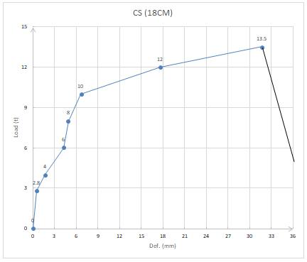
For specimen CS, where layer thickness was 180 mm with no additional layer to be as a control and reference slab, vertical cracks started to appear at the mid of the Slab adjacent to the face of the rigid base. By increasing the load, the cracks extended in the bottom third of the Slab. At failure, crushing of the bottom section of the slab took place and the load dropped suddenly as shown in Fig. (8). The deflection of concrete governed the failure of the slab.

International Journal of Engineering Research and Reviews ISSN 2348-697X (Online)
Page | 5 Research Publish Journals
International Journal of Engineering Research and Reviews ISSN 2348-697X (Online)
Vol. 10, Issue 2, pp: (1-9), Month: April - June 2022, Available at: www.researchpublish.com
Fig. (8) – CS Load - Vertical displacement relationship
- As shown in Fig. (8), the Load - Displacement curve is Nearly linear up to 10ton load and the axial displacement was 6.65mm. after This load value a high increase in Vertical displacement values appeared and can prove certain failure.

Slab Specimen S1
For specimen S1, where layer thickness was 90 mm with additional layer of 90 mm, vertical cracks started to appear at the mid of the Slab adjacent to the face of the rigid base. By increasing the load, the cracks extended in the bottom third of the Slab. At failure, crushing of the bottom section of the slab took place and the load dropped suddenly as shown in Fig. (9). The deflection of concrete governed the failure of the slab.
Fig. (9) – S1 Load & Vertical displacement relationship
- As shown in Fig. (9), the Load - Displacement curve is Nearly linear up to 18ton load and the axial displacement was 10.20mm. after This load value a high increase in Vertical displacement values appeared and can prove certain failure.
Slab Specimen S2
For specimen S2, where layer thickness was 100 mm with additional layer of 80 mm, vertical cracks started to appear at the mid of the Slab adjacent to the face of the rigid base. By increasing the load, the cracks extended in the bottom third of
Page | 6 Research Publish Journals
International Journal of Engineering Research and Reviews ISSN 2348-697X (Online)
Vol. 10, Issue 2, pp: (1-9), Month: April - June 2022, Available at: www.researchpublish.com
the Slab. At failure, crushing of the bottom section of the slab took place and the load dropped suddenly as shown in Fig. (10). The deflection of concrete governed the failure of the slab.
Fig. (10) – S2 Load - Vertical displacement relationship
- As shown in Fig. (10), the Load - Displacement curve is Nearly linear up to 14ton load and the axial displacement was 8mm. after This load value a high increase in Vertical displacement values appeared and can prove certain failure.


Slab Specimen S3
For specimen S3, where layer thickness was 120 mm with additional layer of 60 mm, vertical cracks started to appear at the mid of the Slab adjacent to the face of the rigid base. By increasing the load, the cracks extended in the bottom third of the Slab. At failure, crushing of the bottom section of the slab took place and the load dropped suddenly as shown in Fig. (11). The deflection of concrete governed the failure of the slab.
Fig. (11) – S3 Load - Vertical displacement relationship
Page | 7 Research Publish Journals
International Journal of Engineering Research and Reviews ISSN 2348-697X (Online)
Vol. 10, Issue 2, pp: (1-9), Month: April - June 2022, Available at: www.researchpublish.com
- As shown in Fig. (11), the Load - Displacement curve is Nearly linear up to 14ton load and the axial displacement was 8mm. after This load value a high increase in Vertical displacement values appeared and can prove certain failure.

Load – Vertical displacement relationship between S1 & S2 & S3 & CS
Fig. (12) - Load - Vertical displacement comparison between S1 & S2 & S3 & CS
V. CONCLUSION
Based on the experimental and analytical studies carried out in this study, the following conclusions can be carried out as following:
1- All strengthened slabs proposed in this study showed generally better behavior in load capacity and deflection results.
2- The study showed that all specimens including the control slab “CS” begins to have some cracks at the same time (6ton axial load).
3- The displacement at 6ton load for each specimen including the control slab “CS” has almost the same results with minor variance can be neglected and considered to be the same value.
4- The separation between the two layers of slabs “S1 & S2” begins to appear at 18ton.
5- The separation between the two layers of slabs “S3” begins to appear at 16ton.
6- The results indicate that the separation begins to appear faster when the strengthening done in a place above the specimens C.G.
7- The results indicate that the deflection results of all specimens including the control slab “CS” are nearly same comparing with the control slab “CS” and its max. moment & load capacity.
Page | 8 Research Publish
Journals
International Journal of Engineering Research and Reviews ISSN 2348-697X (Online)
Vol. 10, Issue 2, pp: (1-9), Month: April - June 2022, Available at: www.researchpublish.com
8- The results indicate that the deflection results for all specimens including the control slab “CS” are accepted comparing the results with the allowable deflection for all slabs according to the ECP.
Allowable def. = L/250 , 1500/250 = 6mm.
CS def. = 2.51mm “ok”.
S1 def. = 2.27mm “ok”.
S2 def. = 2.56mm “ok”.
S3 def. = 2.30mm “ok”.
9- All strengthened slabs with variable thickness are accepted to be used safely according comparing the results with calculation according to the ECP.
VI. RECOMMENDATIONS
From the present study, by using different slabs thickness for strengthening by shear dowels, it can be recommended that;
1- Using the shear dowels with min. requirements to connect two layers of concrete without adding any chemical bond is highly recommended economically.
2- Slabs behavior almost giving high performance in a place close to the slabs C.G.
REFFRENCES
[1] Bijen, J., Salet, T. Adherence of young concrete to old concrete development of tools for engineering, Wittman FW (ed) Proceeding of 2nd Bolomey workshop on adherence of young on old concrete, 1994
[2] Calixto, J. M., Pires, E. F., Lima, S. A., Piancastelli, E. M., Behavior of reinforced concrete slabs
[3] strengthened in flexure by concrete overlays, ACI Structural Journal, Vol. 229, 2003, p. 389-406 Hussien, I.A., “Effect of Shear Connectors on Composite Concrete Beams”, M.Sc. Thesis. Faculty of Eng. Cairo Univ., 1991
[4] H.Abbas et al. / Effect of CFRP and TRM Strengthening of RC Slabs on Punching Shear Strength 161
[5] Shear distribution in the reinforced concrete slab under concentrated loads as a result of non-linear finite element analysis - Chalmers reproservice, Göteborg, Sweden 2013
[6] De Lorenzis, L., A. Nanni, and A. La Tegola, "Strengthening of Reinforced Concrete Structures with Near Surface Mounted FRP Rods", bibl. International Meeting on Composite Materials, PLAST 2000, Milan, Italy, May 9-11, 2000
[7] U. Ebead, H. Marzouk, and L. M. Lye Faculty of Engineering and Applied Science, Memorial University of Newfoundland, St. John’s, NF, Canada A1B 3X5
[8] Adel A. AI- Azzwi and Abbas J., AL-Asdi Department Civil of Engineering, Al-Nahrain University, Baghdad, Iraq
Page | 9 Research Publish Journals