
Vol. 10, Issue 1, pp: (37-44), Month: January - March 2022, Available at: www.researchpublish.com
IMPROVING WIND TURBINE SPEED CONTROL USING PITCH and YAW ADJUSTMENT TECHNIQUE
Odeh Adehi Alex1, Innocent I. Eneh2, Nwogwu J. Kelechi3, Okechukwu Cletus1, 2, 3, 4
Department of Electrical and Electronic Engineering, Faculty of Engineering, Enugu State University of Science and Technology, Enugu State, Nigeria
4
Abstract: This work presents the improvement of a wind turbine system using pitch and yaw adjustment controller. The aim is to optimize the performance of a traditional wind turbine system characterized with a PID controller to produce a better power quality output. This was achieved using the structural and mathematical design methods. The materials used for the development are the asynchronous motor, pitch and yaw adjustment adaptive controller, breakers, wind turbine, and condenser. The materials were designed using a process modelling technique which integrates the components using the wind turbine model, model of the controller, model of the motor, model of the turbine dynamics considering the coefficient of the turbine blade angle. The models were investigated using simulink, tested and compared with the conventional wind turbine. The results show that the adaptive controller was able to adjust the turbine to maximize wind extraction at 12ms, compared to the characterized turbine without adaptive controller at 47ms. The percentage improvement in the controller response performance is 25.5% achieved with the percentage difference between the conventional system response time and new system response time.
Keywords: Wind turbine speed control, Pitch and Yaw, adjustment Technique, Adaptive controller, Turbine blade angle.
I. INTRODUCTION
A wind turbine is a rotating / revolving machine that undergoes two energy conversion processes, the first process is to convert the kinetic energy from the wind into mechanical energy and the second process is to convert the mechanical energy into electrical energy before it is been fed to the grid. The wind turbine consists of components that are saddled with the responsibility for these energy conversion processes they are rotor and the generator. The main driving force in a wind turbine system is wind speed, as we all know wind speed is not constant, there are days we experience high wind speed and there are days we experience low wind speed, on the days we experience high wind speed the turbine blades tends to rotate faster and it affects the output of the generator similarly on the days we experience low wind speed the turbine blades tend to rotate slowly and it affects the output of the generator as well. Hence there is need to incorporate a control mechanism to the system that will help to adapt, control and adjust the turbine blade angles to provide a prescribe speed for the turbine blades to rotate so as to deliver a stable generator output. To achieve control for the wind turbine system, the pitch and yaw adjustment technique was employed. This paper focuses on controlling a turbine by controlling the speed of the turbine blade by adjusting the turbine blade angle. Adjustment of the blade is also referred to as “Pitch adjustment” while control of the turbine rotation is known as “Yaw adjustment”.
The aim of pitch control is to ensure that the blade is maintained at optimum angle to achieve certain rotor speeds or output power. Pitch adjustment can also be utilized to achieve stall and furl, which are the two methods of Pitch control. When the wind turbine is stalled the angle of attack is increased which causes the flat side of the blade to turn further into the wind while Furling on the other hand decreases the angle of attack, causing the edge of the blade to turn to the direction of the oncoming wind [1].
International Journal of Electrical and Electronics Research ISSN 2348-6988 (online)
Page | 37 Research Publish Journals
International Journal of Electrical and Electronics Research ISSN 2348-6988 (online)
Vol. 10, Issue 1, pp: (37-44), Month: January - March 2022, Available at: www.researchpublish.com
Pitch angle adjustment is the most effective means to control power output by changing aerodynamic force on the blade at a very high wind speed [2]. Yaw refers to the rotation of the entire wind turbine on the horizontal axis. The yaw control makes sure that the turbine is constantly facing the direction of the wind to maximize the effective rotor area, because wind direction can vary quickly, the turbine may not align with the oncoming wind and cause power output losses.
II. PREVIOUS RELATED WORKS
Since the start of twenty first century, there has been huge expansion in the requirement for sustainable power. The explanation is because of the enormous ward and consumption of the traditional energy sources, for example, petroleum derivative which is nearly getting depleted and other natural difficulties like environmental change it presents. The change to sustainable power source has additionally expanded inside beyond forty years with significant spotlight on wind and photovoltaic energy sources. From the information of the worldwide energy organization [3]
The world encountered a yearly development pace of 22% in wind energy commitment somewhere in the range of 2008 and 2013. The development rate further increments and as at 2020 the IEA have recorded over 580GW limit of force produced from wind turbine internationally [3].
Wind turbine is an electrical machine which converts wind energy to mechanical energy and consequently electrical energy by the utilization of alternators, acceptance engines, or coordinated engine types. The electrical machine is planned as a wind turbine to handle wind energy, which today is the most generally utilized sustainable power on the planet [4].
[6]. Explored the different advances utilized for wind turbines and group them as fixed and variable breeze speed turbines. The decent speed wind turbine worked at a consistent speed regardless of the wind speed and has restricted proficiency while the variable speed turbine creates the most noteworthy effectiveness over high wind speed, adjusting continually. Its rotational speed ωr so the tip speed proportion ⋋is kept consistent at a predefined esteem that relates to the most extreme force coefficient.
III. DESIGN METHODOLOGY
The methodology used for the research design was guided by computer aided software engineering methodology and the IEC standard for development of wind turbine. Before the system development case study, the wind plant was studied for data collection and analysis. This new system was then developed using mathematical models and then implemented with Mathlab tool.
3.1 Data Collection
Data for this work was obtained from the Vergnet 10MW wind farm installed at Katsina state, Nigeria. The data was collected using the company SCADA system which monitors the behaviour of the wind farm and the amount of energy extracted and converted to power using the power meter. The models were used to measure the wind turbine performance using the turbine speed, power and pitch angle performance as presented in the system modelling section. The data collected is presented in table 1 below;
Table 1: Characterized Performance of the Turbine
Report Date cp -λ Turbine Speed (m/s) Pitch angle (β) Wind Speed (rad/s) PID response time (s)
Feb 09 2019 11:35:00 EDT 0.5176 14 0.75 19 40.854
Feb 09 2019 11:30:00 EDT 116 14 0.75 19 40.852
Feb 09 2019 11:25:00 EDT 0.4 14 0.75 19 40.754
Feb 09 2019 10:35:00 EDT 5 8 0.75 15 40.824
Feb 09 2019 09:35:00 EDT 21 6 0.64 13 40.814
Feb 09 2019 07:35:00 EDT 0.0068 10 0.60 12 40.717
Feb 09 2019 06:35:00 EDT 104 11 0.64 13 40.744
Feb 09 2019 05:35:00 EDT 0.3 7 0.64 13 40.816
Feb 09 2019 04:35:00 EDT 3 13 0.62 12 40.845
Feb 09 2019 03:35:00 EDT 17 10 0.64 13 40.840
Feb 09 2019 02:35:00 EDT 0.0045 12 0.75 15 40.024
Feb 08 2019 23:35:00 EDT 98 12 0.75 19 40.855
The data was obtained using the instrumentation tool and was used to analyze the wind turbine performance based on the pitch adjustment, speed and control performance to determine the turbine behaviour. The data obtained from table 1 was used to plot the control response time graph shown in figure 1;
Page | 38 Research Publish Journals
International Journal of Electrical and Electronics Research ISSN 2348-6988 (online)
Vol. 10, Issue 1, pp: (37-44), Month: January - March 2022, Available at: www.researchpublish.com
Fig. 1: controller response to wind dynamics graph
From the graph it can be deduced that the characterized controller detect the pitch angle dynamics at 7ms and then control it at 47ms which is too much a delay time for optimized power output and quality. Hence there is need for an improved controller for fast adjustment of the pitch angles.
3.2 System Design
The system design of the wind farm was developed using the wind turbine model, the generator model and the improved controller.
3.2.1 Design of the wind turbine
The model of the wind turbine was developed using the relationship between the wind characteristics such as performance coefficient, motor characteristics, pitch angle, air density and the output power characteristics. The model is presented as shown below [6];
( ) (1)
Where Pm is the mechanical output of the wind turbine in watts, cp is the performance coefficient of the turbine, is the rotor blade speed ratio, is the pitch angle, A is the swept area of the turbine, ρ is the air density and v is the wind speed. From the model in equation (1); the ( ) presented the performance coefficient of the turbine with relation to the motor characteristics like the blade pitch and speed ratio. They are related using the model in equation 3.2 as [6];
( ) = ( ) ( ) (2)
Where is specified as ; the equation (1); which is the wind energy was controlled using the relationship between the power gain, wind speed, performance coefficient and nominal power as shown in the equation (3);
(3)
Where presented the nominal power for the turbine swept area and wind density; presented the performance coefficient, is the wind speed and is the controlled power gain.
3.2.2 Model of the Asynchronous Motor
The model of the motor was developed considering the relationship between the rotor and stator characteristics of the turbine as shown in the structure of equation (1); The Rotor slip (S) is defined in terms of rotational speed ωm, the number of pole pair’s p, and the electrical supply frequency ω. Thus related by the structure [7];
S = (4)
Page | 39 Research Publish Journals
International Journal of Electrical and Electronics Research ISSN 2348-6988 (online)
Vol. 10, Issue 1, pp: (37-44), Month: January - March 2022, Available at: www.researchpublish.com
Response time model
The model presented the general equation for the response time of the conventional controller using the step input model in equation (5);
( ) ( ) ⁄ ) (5)
Where is the initial blade output and input signal from wind extracted; is the final predicted output from the dynamic turbine transfer function, t is the time, n is the system order which is this case is a second order system.
3.2.3 Model of the adaptive integral feedback pitch and yaw controller
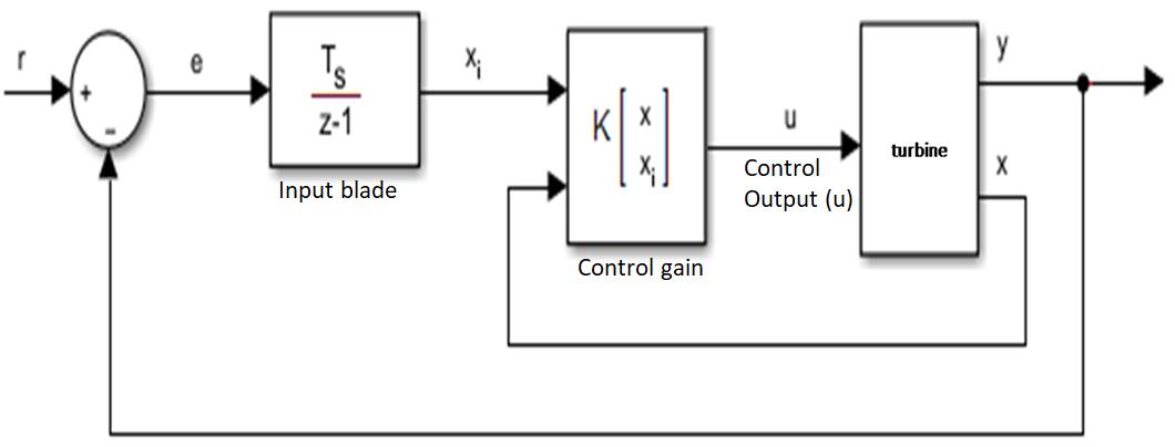
This controller is a discrete time state feedback controller with integral action to control multiple input of the wind angular velocity (yaw) and rotational dynamics of the blades (pitch) of the wind turbine (plant). The integral of the tracking error, xi, is an additional state that ensures zero steady-state error for the closed-loop system. The equivalent model of the adaptive feedback pitch and yaw controller is presented as shown below;
Fig. 2: Equivalent Block Model of the Adaptive Controller
Where x is the state vector., xi is the integral of the tracking error., xe is the extended state vector, K is the feedback matrix. The model shows the performance of the adaptive controller developed which collects aerodynamics parameters from the turbine blades as input. The controller was programmed with pitch angle set point of 1.0 (ß) and wind reference speed of 15m/s and used these values to adjust the turbine performance when these set points are not satisfied. The aerodynamic data collected is then fed to the power converter for processing into electric energy.
3.3 Implementation of the Model
This section presented the implementation of the models developed using simulink tool. The model presented the design of a 10MW capacity wind turbine system integrated on the conventional power line as an on grid network. The wind turbine was developed using the turbine model in equation (1) for the output power generated and the synchronous motor was modelled with equation (3). The figure 2 which is the adaptive controller was used to improve and regulate the speed of the turbine to maximize energy extraction. The simulink block of the adaptive controller is presented in figure 3;
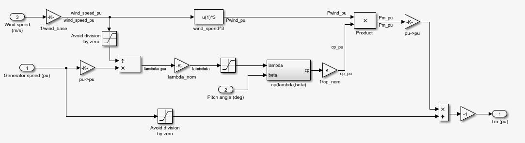
Fig. 3: Simulink model of the adaptive controller
Page | 40 Research Publish Journals
International Journal of Electrical and Electronics Research ISSN 2348-6988 (online)
Vol. 10, Issue 1, pp: (37-44), Month: January - March 2022, Available at: www.researchpublish.com
The figure 3 presented the transfer function model of the adaptive controller developed. This controller was implemented on the 10MW wind farm as shown in the simulink model of figure 4;

Fig. 4: Model of the Turbine and Adaptive Controller Performance
The simulink shows the internal architecture of the wind farm. This was developed using the wind turbine model in equation 3.1, the asynchronous generator model in equation 3.4 and the controller designed using the transfer function model in figure 3.
IV. RESULTS AND DICUSSIONS
4.1 Results
The results presented the performance of the wind turbine with the adaptive integral controller which was used to optimize the wind energy extraction ability. The turbine with the help of the controller tracks the extracts maximum energy from the wind based on the input wind characteristics like the yaw, pitch and speed of the wind. The controller employs these parameters as input to manipulate the blades in correspondence with the direction of wind.
4.2 Performance of the Adaptive integral controller on the case study turbine
The controller developed was installed on the case study wind turbine and then tested. The essence is to collected data which will be used for the validation of the system using a comparative approach with the characterized data collected. The wind turbine instrument was used here to collect the response time data of the two controllers to be compared and the result presented as shown below;
Table 2: Comparative result of the controller performance
Report Date cp -λ
Turbine Speed (m/s)
Pitch angle (β) Wind Speed (rad/s) PID response time (s)
Feb 09 2019 11:35:00 EDT 0.5176 14 0.75 19 12.054
Feb 09 2019 11:30:00 EDT 116 14 0.75 19 12.052
Feb 09 2019 11:25:00 EDT 0.4 14 0.75 19 12.054
Feb 09 2019 10:35:00 EDT 5 8 0.75 15 12.024
Feb 09 2019 09:35:00 EDT 21 6 0.75 15 12.014
Feb 09 2019 07:35:00 EDT 0.0068 10 0.75 15 12.017
Feb 09 2019 06:35:00 EDT 104 11 0.75 15 12.044
Feb 09 2019 05:35:00 EDT 0.3 7 0.75 15 12.016
Feb 09 2019 04:35:00 EDT 3 13 0.75 15 12.045
Feb 09 2019 03:35:00 EDT 17 10 0.75 15 12.040
Feb 09 2019 02:35:00 EDT 0.0045 12 0.75 15 12.024
Feb 08 2019 23:35:00 EDT 98 12 0.75 19 12.055
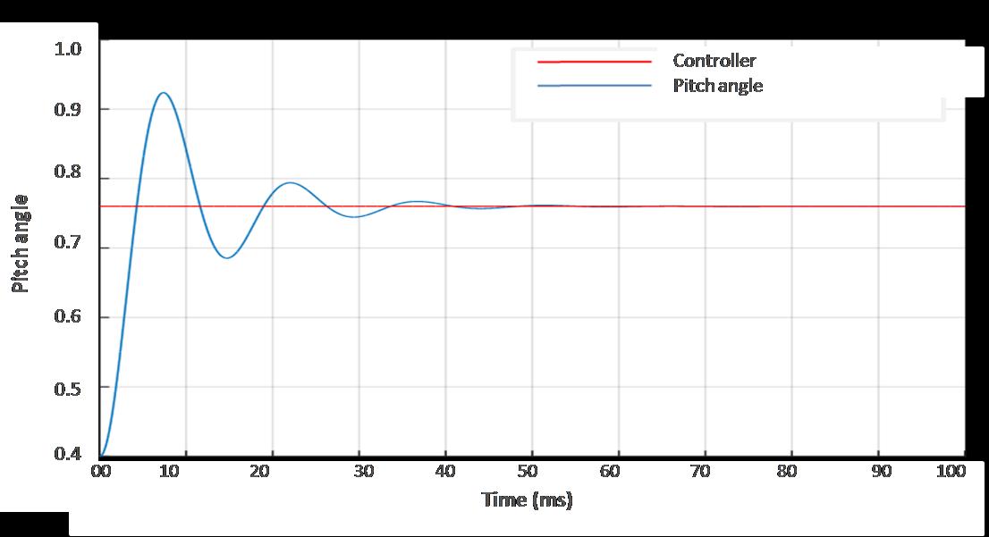
The figure 5 presented the performance of the pitch angle which the new turbine recorded; it was observed that the controller was able to adapt the pitch angle to a reference set point of 0.75 as this was achieved such that the aerodynamics variation in input source did not affect the quality of energy generated at the output.
Page | 41
Research Publish Journals
International Journal of Electrical and Electronics Research ISSN 2348-6988 (online)
Vol. 10, Issue 1, pp: (37-44), Month: January - March 2022, Available at: www.researchpublish.com
Fig. 5: Pitch Angle Performance of the Wind Turbine
The figure 5 presented the pitch angle performance of the blades when the controller identified the wind speed and adjusted the blades immediately to extract maximum wind data. The next result was used to analyze the adaptive integral control performance based on response to wind speed dynamics.
Fig. 6: The Adaptive Controller Response Time Graph
From the controller performance as shown in figure 6, it was observed that the adaptive controller was able to detect pitch angle dynamics at 10ms and adapt the blades of the turbines to the wind dynamics within 12ms. This low delay time is negligible and is a very good time response to wind speed dynamics and pitch angle variation.

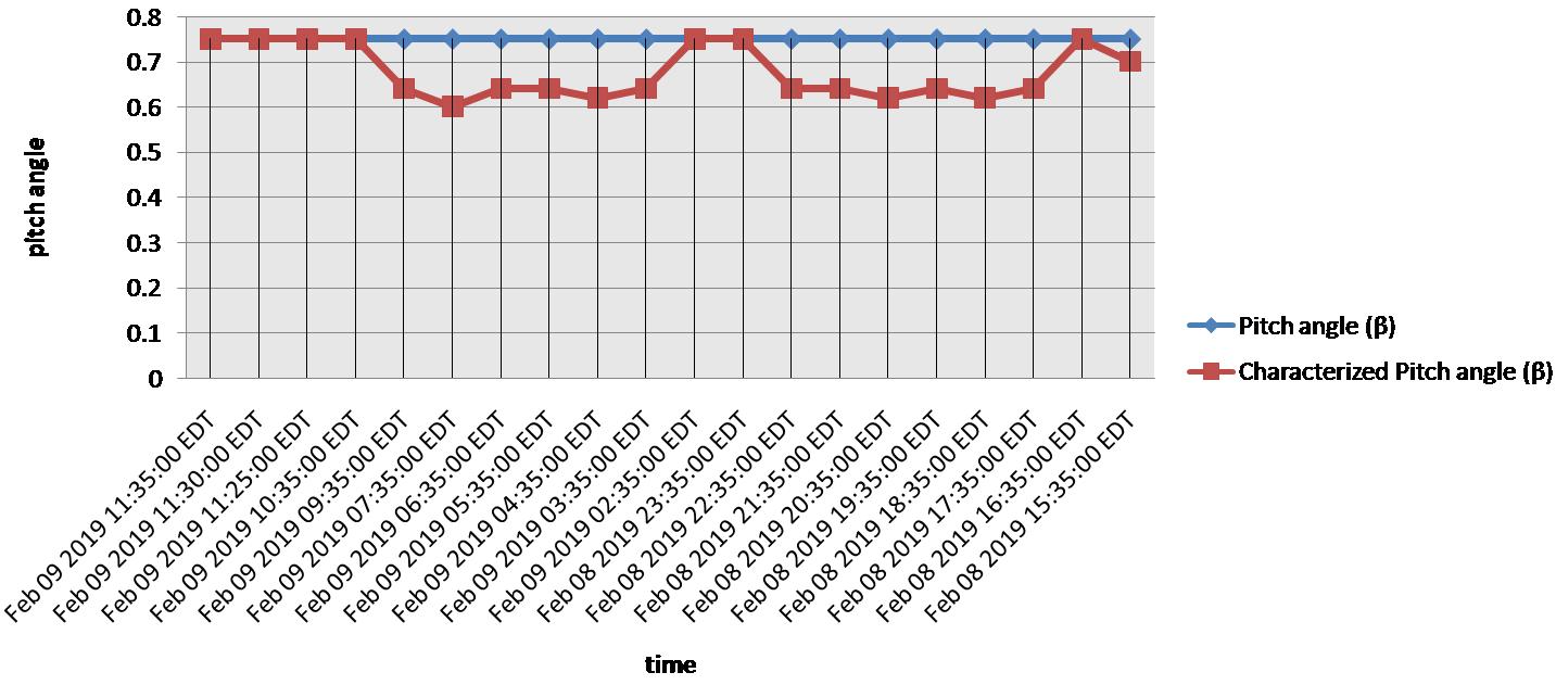
The result in table 2 presented a comparative result of the adaptive integral feedback controller and the PID used for the characterization. The instrumentation tool ZR300 LS instrument meter was again used to analyze the data collected and the result presented as shown below;
Fig. 7: Comparative Pitch Angle Performance

Page | 42 Research Publish Journals
International Journal of Electrical and Electronics Research ISSN 2348-6988 (online) Vol. 10, Issue 1, pp: (37-44), Month: January - March 2022, Available at: www.researchpublish.com
From the result it was observed that the new controller was able to aerodynamics nonlinear behaviour of the wind turbine affects the characterized PID controller; in the other hand the adaptive controller already programmed with a set point for wind speed and pitch angle at a reference angle of 0.75.
Result of Comparative controller step response
The comparative response time which compares the performance of the wind turbine with the adaptive controller and the characterized wind turbine without adaptive controller is presented as shown in table 3;
Table 3: Comparative response performance
Values Characterized New adaptive controller Control time (ms) 47 12
The table 3 presented the comparative response performance of the controllers in the wind turbine. The percentage improvement in the control performance is 25.5%. The result is graphically analyzed as shown in figure 7;
50
40
30
20
10
0
Control time (ms) Comparative Controllers
Characterized New adaptive controller
Fig. 8: comparative controller performance
Control time
The figure 8 presented the percentage improvement of the step response of the new wind turbine and the characterized wind turbine without adaptive controller. The result showed that the control performance of the adaptive controller to adjust the turbine blade to wind direction is 35ms faster than without the adaptive controller.

V. CONCLUSION
This work has successfully developed an improved wind turbine system using the pitch and yaw adjustment controller. The work was achieved by restructuring the design of a traditional wind turbine system characterized with the new controller developed. The controller was designed to boast the performance of the turbine through the adjustment of the pitch coefficient. The implication is to ensure a close dynamics in operation with respect to wind speed. This is because the faster the turbine rotates, the more and stabilized energy generated. The new controller was able to react to wind dynamics within 12ms compared to the characterized controller at 47ms. When the response time was compared to the characterized PID controller, the result shows that the adaptive controller responded faster with a difference of 35ms. The overall percentage improvement in the controller response performance is 25.5%.
REFERENCES
[1] Tazil M, Kumar V, Bansal RC, Kong S, Dong ZY, Freitas W, Mathur HD. Three-phase doubly fed induction generators: an overview. IET Electric Power Applications 2010; 4(2):75–89.
[2] Abad G, Lopez J, Rodriguez M, Marroyo L, Iwanski G. (2011) “Doubly Fed Induction Machine: Modelling and Control for Wind Energy Generation”. Wiley; 625 pp
[3] IEA (International Energy Agency) (2014), “Energy Technology Perspectives,” OECD/IEA, Paris,
Page | 43 Research Publish Journals
International Journal of Electrical and Electronics Research ISSN 2348-6988 (online) Vol. 10, Issue 1, pp: (37-44), Month: January - March 2022, Available at: www.researchpublish.com
[4] Gelma Boneya. Design of a Photovoltaic -Wind Hybrid Power Generation System for Ethiopian Remote area, PhD thesis, Institute of Technology Department of Electrical and Computer Engineering, Addis Ababa University, 2017
[5] Manjunath TC, Kusagur A, Sanjay S, Sindushree S, Ardil C. (2008)” Design, Development & Implementation of a Temperature Sensor using Zigbee Concepts”. World Academy of Science, Engineering and Technology
[6] E. Simley and L. Pao, “Correlation between rotating LIDAR measurements and blade effective wind speed,” in 51th AIAA Aerospace Sciences Meeting Including the New Horizons Forum and Aerospace Exposition, Dallas, USA, 2013.
[7] E. Bossanyi, B. Savini, M. Iribas, M. Hau, B. Fischer, D. Schlipf, T. van Engelen, M. Rossetti, and C. E. Carcangiu, “Advanced controller research for multi-MW wind turbines in the UpWind project,” Wind Energy, vol. 15, no. 1, pp. 119–145, 2012
Page | 44 Research Publish
Journals