
Elimination and Identification of Harmonic Pollution by Active Compensation Scheme in Radial System
Daniel Manoj Nethala1, Sunil Kumar.V2, Dr.P.Santosh Kumar Patra31,2Assistant Professor, 3Principal & Professor in CSE St.Martin’s Engineering College, Secunderabad, Telangana, India.
Abstract: This paper proposes an appropriated active compensation method for eliminating the harmonic pollution in a distribution network. The proposed distributive active compensation scheme covers a number of multi active component filter units that were started at the same area or various areas within the power systems. Optimum positioning of Active compensation stays on dragging in momentous observation, in view of the strong effect on power efficiency and advancement of semiconductor power devices by users. Active filter channel innovation is the most productive approach to repay and counteract the voltage distortions hailing from nonlinear loads and this Numerous Distributive Active Compensation (NDAC) worked as a shunt compensation scheme from the congregation of nonlinear loads, so the ensuring collective voltage drawn from the ac source is sinusoidal. Droop housing in between the harmonized conductance and the volt-ampere (VA) of the AFU is modified into the controller of each one unit, so diverse AFUs can communicate the workload of harmonic minimization without any correspondences. The compensation process is focused around idea of PQ theory. This proposed numerous distributive active compensation schemes is tested on 9-bus radial as well as non-radial distribution systems is verified and simulated through MATLAB-SIMULINK environment.
Keywords: Distributive active compensation scheme, Active filter units, Power quality, Harmonic Pollution, Total Harmonic Distortion (THD).
I. INTRODUCTION
Evolution of dispersed generation and deregulated electricity markets will force electric utilities to be more concerned about power-quality (PQ) problems, especially harmonics. There are various sources of harmonic pollution in the power network with nonlinear loads and dispersed generators that use power-conditioning units as the main sources.
Identifying the source of harmonic pollution is the first step toward improving the PQ of the network. A great number of nonlinear loads like adjustable speed drives and static power switches including those of higher capacity ground the power quality strife. The Power Quality is the combination of voltage quality and current quality [1].One of the major power quality issue that affects the end user is harmonics. The total and individual voltage harmonic distortions are limited to 5% and 3% respectively as per the guideline given by IEEE 519-1992 standard [2]. Nonlinear loads are continuously increasing. Harmonics have become an important power quality problem because of the increased distortion levels in the power system as a result of an increasing number of harmonic producing loads [3, 4]. The main effects of harmonics in power systems are heating, overloading, aging of equipment, increased losses and system unbalancing. Harmonics may lead to malfunctioning of power system components and electronic devices. Relays and measurement equipment may function erroneously under non-sinusoidal voltage and currents.
These harmonics can be mitigated by adopting various mitigation techniques including passive and active filtering techniques. Among these, passive filters are adopted often since it is easy to install and less cost. Various types of passive filters have been proposed to mitigate the harmonics along radial distribution system (RDS) [5]. Resonance is the major problem occurring due to the incorporation of passive filters along a radial distribution system. The recent manifestation
International Journal of Electrical and Electronics Research ISSN 2348-6988 (online) Vol. 8, Issue 2, pp: (14-22), Month: April - June 2020, Available at: www.researchpublish.com
of Nonlinear Load (NLD) in the Electric Power System aggravated harmonic distortion in the network voltages. This fact and the increasing number of applications with NLD have led us to analyze the harmonic problem in Radial Distribution System. Fig.1. circuit shows the linear and nonlinear loads in radial network system.
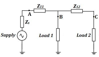
Fig. 1. Linear and Nonlinear Loads in Radial Network
The procedures used for analyzing the harmonic problem can be classified into two categories. They are time domain and frequency domain approach. In the proposed work the RDS is polluted by the inclusion of nonlinear device. The maximum polluted bus due to harmonic penetration is identified based on Total Harmonic distortion value and passive harmonic filter is placed at the scrupulous location to suppress the harmonics. Harmonic analysis is then applied to the study of resonant conditions in network, harmonic filter designs and also to investigate other effects of harmonics on the power system, i.e., notching and ringing, neutral currents, saturation of transformers, and overloading of system components. Identification and measurement of harmonic producing load has become an important issue in electric power systems since increased use of power electronic devices and equipment sensitive to harmonics has increased the number of adverse harmonic related events. Many methods have been proposed to solve the harmonic pollution produced by nonlinear loads. The commonly used harmonic analysis methods can be divided into two categories. The first category is based on the transient-state analysis techniques, such as the time domain analysis and Wavelet analysis, etc. [6]–[8]. The second category is the steady-state analysis [9]–[11]. In this method, a harmonic current source of specified magnitude is injected into a linear network to determine the voltage distortion level. One of the limitations of this method is that in the presence of multiple harmonic sources, a fundamental frequency load flow is required to determine the magnitudes and phase angles of the injected currents accurately. Another drawback of frequency scan is its reliance on typical harmonic spectra to represent nonlinear devices. This results in inaccurate results under conditions of voltage-dependency, unbalanced operation, and the generation of non-characteristic harmonics. The steady-state algorithms are developed based on load-flow programs and employed frequency-based component models. The steady state-based algorithms are more efficient than the transient state-based algorithms. Steady state-based algorithms are better choice for large-scale power system analysis due to the computational economy.
Past written works propose the establishment of active compensation channel at the end of radial lines to damp-out the harmonic resonance Moreover, dependence on the greatness of the damping provision by the active channel, the level of harmonic distortions may get more regrettable at specific areas along the radial lines. Various establishments of active channels have been exhibited, yet continuous correspondences among different units are obliged to arrange the operations. A numerous distributive active compensation scheme is proposed in this paper to eradicate the voltage harmonic distortions of power system network focused around reference qualities created by PQ reference generation theory. The proposed compensation scheme comprises of a few active filter units (AFUs) that are introduced on different areas with optimal location and every unit works as a harmonized conductance to mitigate the voltage harmonics. The AFUs of the NDAC can impart the harmonic elimination workload without any interchanges among them.
II. PROPOSED IMPROVED NUMEROUS DISTRIBUTIVE COMPENSATION SCHEME
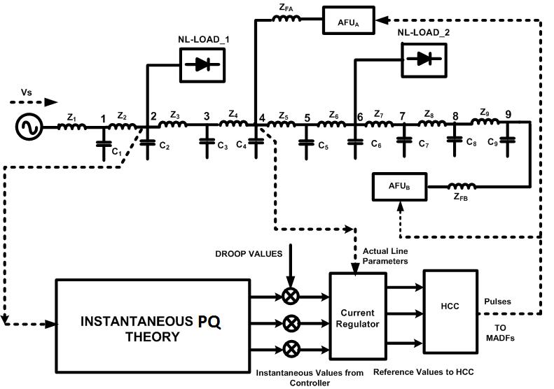
Streamlined proposed schematic diagram of numerous compensation schemes is demonstrated in Fig.2. A few AFUs, including AFUx, AFUy, and AFUz, are introduced along the line. With a specific end goal to eradicate the voltage harmonics, the AFUs work as a harmonic conductance [12]. The shunt recompense procedure is focused around the id-iq theory; it gives great remuneration attributes in unfaltering state and additionally transient states. The id-iq theory produces the reference currents needed to remunerate the contorted voltage harmonics and enhance the THD values which require the straightforwardness of the calculations, which includes just algebraic logarithms. This feature is refined by the droop relationship in between the harmonized conductance order and the volt-ampere (VA) of every active channel. The slant of the droop is dictated by the volt-ampere rating of the filter units to ensure that the offering of filtering workload is in extent with the limit of the active filter
International Journal of Electrical and Electronics Research ISSN 2348-6988 (online)
Vol. 8, Issue 2, pp: (14-22), Month: April - June 2020, Available at: www.researchpublish.com
Fig. 2. Proposed Schematic Diagram of Numerous Compensation Scheme
Execution of prompt instantaneous & quadrature current (id-iq) control procedure for concentrating on reference currents of shunt active filter units under diverse voltage conditions. PWM design era focused around carrier-less hysteresis based current control is utilized for fast response in [13]. The droop control permits different power era units to impart the load equitably without any inter-changes; subsequently the unwavering quality of the framework is incredibly improved. Also, on differentiation of diverse control methodologies; id-iq strategy is utilized for acquiring reference currents within the system, in light of the fact that in this system, angle "θ" is calculated specifically from primary voltages and empowers operation to be recurrence free their by method evades huge amounts of synchronization issues. It is additionally observed that DC voltage regulation system substantial to be an operated as stable and steady-state-error free framework was achieved in [14], [15].
A. Proposed Current control strategy:
The reference current generator block generates the reference current to be injected into the grid upon sensing the voltage at the Point of Common Coupling (VPCC) and load currents using instantaneous active and reactive power (p-q) theory. For the computation of p and q, the three phase voltages at the point of common coupling (PCC) and load currents must first be transformed to the stationary two axis (α-β) co-ordinates. The instantaneous real and reactive power p and q are determined using equations
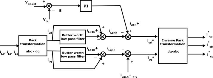
Both instantaneous power quantities p and q consists of dc and ac components. While the dc components p and q arise due to the fundamental, the ac components p and q are a result of harmonic components. To provide harmonic as well as reactive power compensation as per the load demand, the reference for active and reactive power is generated. The ac component is determined by first extracting using a very low cut off low pass filter and then subtracting it from p obtained using. Finally, the reference currents are generated as per (3) and (4). Fig.3. shows the Extraction of Reference Currents based on Id-Iq Transition Methodology
International Journal of Electrical and Electronics Research ISSN 2348-6988 (online) Vol. 8, Issue 2, pp: (14-22), Month: April - June 2020, Available at: www.researchpublish.com
Fig. 3. Extraction of Reference Currents based on Id-Iq Transition Methodology
a)Hysteresis Current Controller
The hysteresis current controller compares the three phase reference currents ( , , ) generated using with the actual inverter currents (ica ,icb ,icc) and generates the switching pulses as per the logic given below:
leg-a upper switch is OFF and lower switch is ON
leg-a upper switch is ON and lower switch is OFF Where, hb is the hysteresis band around the reference current which is usually 5 % of the maximum current to be injected by the inverter. Similarly, control signals for leg-b and leg-c of the inverter switches are generated. Fig.4. shows the phasor diagram of Instantaneous Voltage and Current Vectors.
Fig. 4. Instantaneous Voltage and Current Vectors.
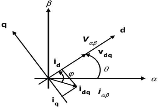
One of the focal points of interest of this strategy is that edge θ is figured specifically from fundamental voltages and subsequently makes this system frequency independent by evading the PLL in the control circuit. Hence synchronizing issues with un-even and misshaped states of principle voltages are additionally evaded. In this way id-iq accomplishes substantial frequency operating limit points basically by the cut-off frequency of voltage source inverter (VSI). On owing load momentums id and iq are gotten from park transformations then they are permitted to pass through the high pass filter unit to take out dc ripples in the nonlinear load currents. Filters utilized within the circuit are butter-worth type and to diminish the impact of high pass filter an alternative high pass filter (AHPF) could be utilized as a part of the circuit.
III. MODELLING AND SIMULATION RESULTS
The proposed numerous placements of improved active compensators are applied to a radial power distribution system to demonstrate its high capability of distributing the harmonic eliminating workload in between several AFUs with id-iq control strategy. The AFUs and nonlinear-loads will be placed at various buses along with the line to test the capability of the proposed system as well as droop control.
International Journal of Electrical and Electronics Research ISSN 2348-6988 (online) Vol. 8, Issue 2, pp: (14-22), Month: April - June 2020, Available at: www.researchpublish.com
Case I: Radial Power Distribution system with Non-linear load With Compensation Schemes.
(a) (b)
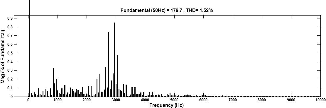
Fig. 5. AFUs are installed at bus 4 and 9 location in radial power line (a) Voltage at bus 2 (b) Bus 2 THD Value is 1.52%. (a) (b)
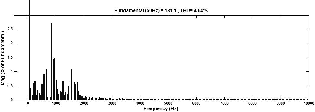
Fig. 6. AFUs are installed at bus 4 and 9 location in radial power line (a) Voltage at bus 3 (b) Bus 3 THD Value is 4.64%.

International Journal of Electrical and Electronics Research ISSN 2348-6988 (online) Vol. 8, Issue 2, pp: (14-22), Month: April - June 2020, Available at: www.researchpublish.com
(a) (b)
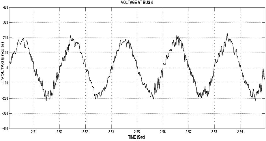
Fig. 7. AFUs are installed at bus 4 and 9 location in radial power line (a) Voltage at bus 4 (b) Bus 4 THD Value is 5.63%. (a) (b)
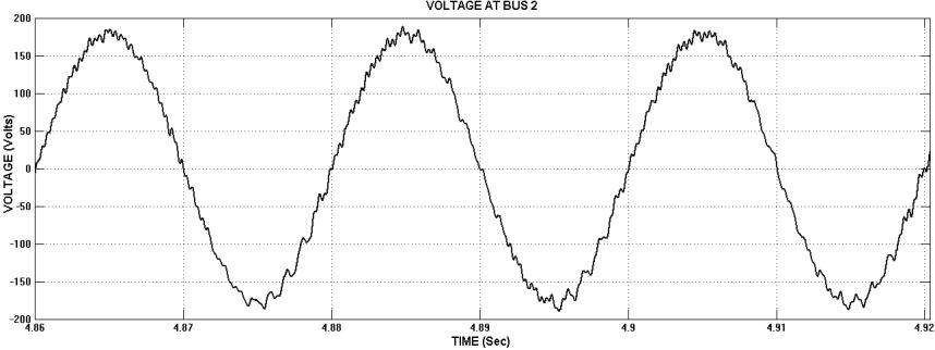
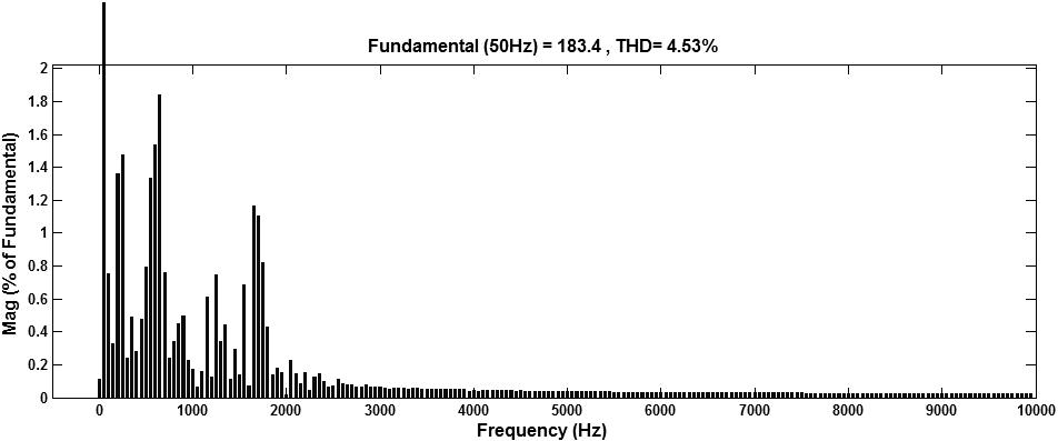
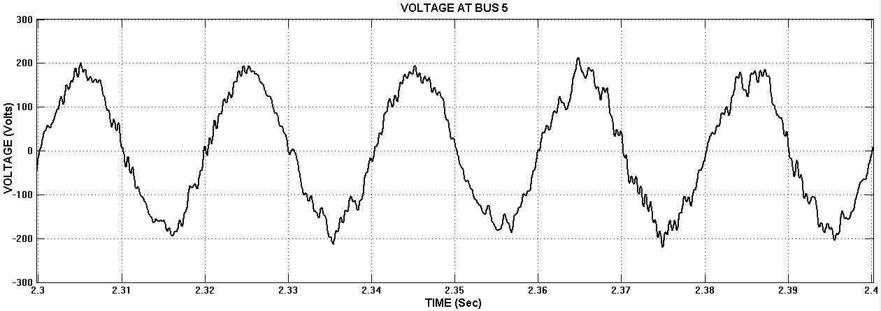
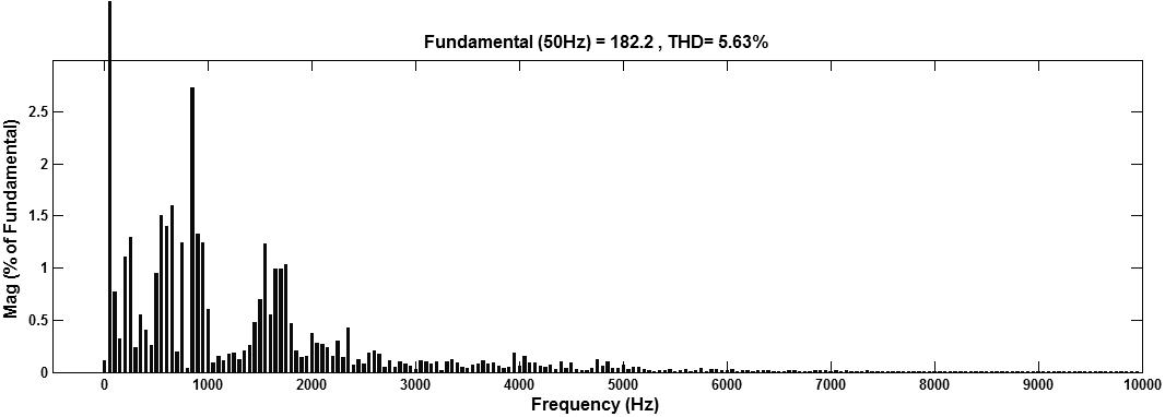
Fig. 8. AFUs are installed at bus 4 and 9 location in radial power line (a) Voltage at bus 5 (b) Bus 5 THD Value is 4.53%.
International Journal of Electrical and Electronics Research ISSN 2348-6988 (online) Vol. 8, Issue 2, pp: (14-22), Month: April - June 2020, Available at: www.researchpublish.com
(a) (b)
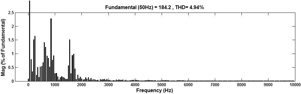
Fig. 9. AFUs are installed at bus 4 and 9 location in radial power line (a) Voltage at bus 6 (b) Bus 6 THD Value is 4.94%. (a) (b)
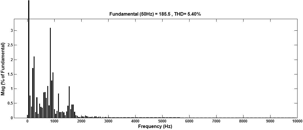
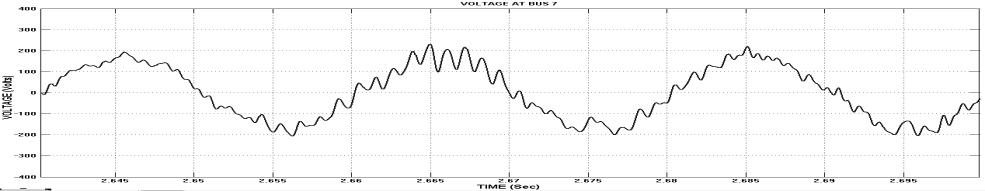
Fig. 10. AFUs are installed at bus 4 and 9 location in radial power line (a) Voltage at bus 7 (b) Bus 7 THD Value is 5.40%.

International Journal of Electrical and Electronics Research ISSN 2348-6988 (online) Vol. 8, Issue 2, pp: (14-22), Month: April - June 2020, Available at: www.researchpublish.com
(a) (b)
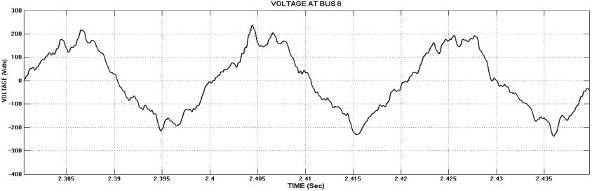
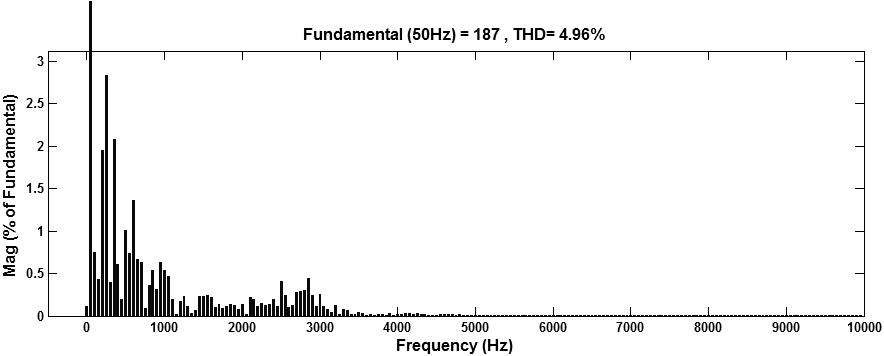
Fig. 11. AFUs are installed at bus 4 and 9 location in radial power line (a) Voltage at bus 8 (b) Bus 8 THD Value is 4.96%.
(a) (b)
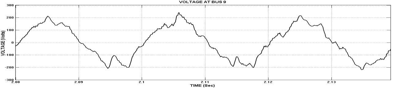
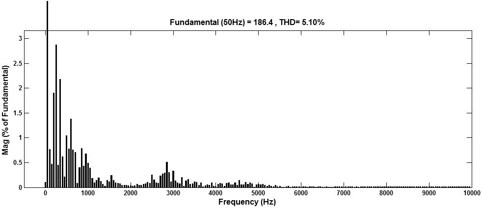
Fig. 12. AFUs are installed at bus 4 and 9 location in radial power line (a) Voltage at bus 9 (b) Bus 9 THD Value is 5.10%.
IV. CONCLUSION
Furthermost active compensation setups, which deliberate on the compensation of current harmonics coming from nonlinear loads, can't satisfactory address this issue. The proposed numerous distributive active compensation scheme can convey a few little assessed AFUs at diverse areas inside the facility to diminish the harmonic resonance. Contrasted with a unified expansive appraised active component, the circulated small rated active channels of the DACS can lessen the harmonics in the power distribution network or in a collecting facility with enhanced expense feasibility. In this paper, the
International Journal of Electrical and Electronics Research ISSN 2348-6988 (online) Vol. 8, Issue 2, pp: (14-22), Month: April - June 2020, Available at: www.researchpublish.com
damping performance of the DACS is assessed under different load areas and diverse organizations of AFUs. The main intention of this proposed DACS to achieve even distribution of harmonic elimination workload among over finest placement of several AFUs by employing successful control technique and need gate-drive circuit. Finally by utilizing this compensation principle the transient responses of radial power distribution system has been enriched and accomplishes short distortions as per the IEEE standards. Harmonic pollution at various buses with AFU’s and without AFU’s is tabulated.
REFERENCES
[1] M.H.J.Bollen, ―What is Power Quality? ‖ Electric Power Systems Research, Vol 66(2003), pp5-14.
[2] IEEE Std 519-1992, IEEE Recommended Practices and Requirements for Harmonic Control in electric Power Systems (ANSI), April 12, (1993).
[3] IEEE standards Board, IEEE Recommended Practice for Electric Power Distribution for Industrial Plants, New York: IEEE, 1994.
[4] IEEE Recommended Practices and Requirements for Harmonic Control in Electric Power Systems, IEEE Std. 5191992, 1993.
[5] S.J.Bester and G.Atkinson – Hope, ―Harmonic Filter Design to Mitigate Two Resonant Points in a Distribution Network‖, Journal of Energy and Power Engineering 6 (2012) 2018-2023.
[6] S. Herraiz, L. Sainz, and J. Clua, ―Review of harmonic load flow formulations,‖ IEEE Trans. Power Del., vol. 18, no. 3, pp. 1079–1087, Jul. 2003.
[7] G. T. Heydt and A. W. Galli, ―Transient power quality problem analyzed using wavelet,‖ IEEE Trans. Power Del., vol. 12, no. 2, pp. 908–915, Apr. 1997.
[8] T. Zheng, E. B. Makram, and A. A. Girgis, ―Power system transient and harmonic studies using wavelet transform,‖ IEEE Trans. Power Del., vol. 14, no. 4, pp. 1461–1468, Oct. 1999.
[9] D. Xia and G. T. Heydt, ―Harmonic power study part I – Formulation and solution, ‖ IEEE Trans. Power App. Syst., vol. PAS-101, no. 6, pp. 1257–1265, Jun. 1982.
[10] D. Xia and G. T. Heydt, ―Harmonic power study part II – Implementation and practical application, ‖ IEEE Trans. Power App. Syst., vol. PAS-11, no. 6, pp. 1266–1270, Jun. 1982.
[11] Y. H. Yan, C. S. Chen, C. S. Moo, and C. T. Hsu, ―Harmonic analysis for industrial customers,‖ IEEE Trans. Ind. Appl. Soc., vol. 30, no. 2, pp. 462–468, Mar./Apr. 1994.
[12] U. Borup, F. Blaabjerg, and P. N. Enjeti, “Sharing of nonlinear load in parallel-connected three-phase converters,” IEEE Trans. Ind. Appl., vol. 37, no. 6, pp. 1817–1823, Nov./Dec. 2001.
[13] P. T. Cheng, C. C. Huang, C. C. Pan, and S. Bhattacharya, “Design and implementation of a series voltage sag compensator under practical utility conditions,” IEEE Trans. Ind. Appl., vol. 39, no. 3, pp. 844–853, May/Jun. 2003.
[14] P. T. Cheng, S. Bhattacharya, and D. Divan, “Experimental verification of dominant harmonic active filter for high power applications,” IEEE Trans. Ind. Appl., vol. 36, no. 2, pp. 567–577, Mar./Apr. 2000.
[15] R. Wu, S. B. Dewan, and G. R. Slemon, “Analysis of a PWM ac to dc voltage source converter under predicted current control with fixed switching frequency,” IEEE Trans. Ind. Appl., vol. 27, no. 4, pp. 756–764, Jul./Aug. 1991.