
International Journal of Electrical and Electronics Research ISSN 2348-6988 (online) Vol. 8, Issue 2, pp: (42-49), Month: April - June 2020, Available at: www.researchpublish.com
DEVELOPMENT OFAN INSTRUMENTATION & CONTROL TRAINER FOR ENGINEERING LABORATORIES
Ysabelle Louiseanne R. Cruto1, Iverson P. Sasis2 and Dave T. Alviz3 ,12Researcher and 3Research Adviser
123
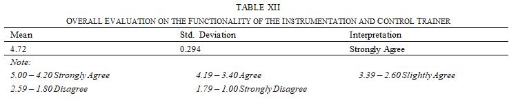
Abstract: The purpose of this research is for engineering students and faculty members, especially electronics, electrical, and mechanical engineering to have an instrumentation and control laboratory trainer that can measure flow rate, water level, temperature, and pressure, and control the latter three parameters. Mixed method was used in this study since this research is both qualitative and quantitative. The results show that the trainer prototype is properly functional as evaluated by engineering students and faculty members. The validation data shows that it has an overall grand mean of 4.72 for its functionality. Hence, it can be concluded that the prototype can properly function as intended and is a reliable trainer for engineering students to learn applications of instrumentation and control. It is recommended that future researchers need to improve the design and add more functions for the prototype such as devices that can provide a more accurate and faster control and materials that can withstand more extreme conditions.
Index Terms: Prototype, trainer, measurement and control.
I. INTRODUCTION
Through the advancement of technology, various instruments have been developed to extend the range of the human senses, measure and observe more quantities in new discovered methods and instrumentation, making the field of knowledge wider and more efficient. Instrumentation is a part of engineering which deals in measuring and controlling physical and chemical properties in a system. In an instrumentation system, there are three stages: input, signal processing, and the output. When the measuring and controlling instruments are combined, providing automation from reactions from signals, result into a control system [1].
Sensor is a device that is able to detect the changes within its range and delivers information or signal to other electronic devices [2]. Transducers are like sensors, but instead, it transforms physical quantity to an electrical signal[3]. Meanwhile, actuator is a device that can be controlled, commonly by an electrical signal, which then causes change in a physical system by means of producing heat, force, light or motion [4].
On-off controller, commonly known as a stop-start, is used for motor controls. On the other hand, PID controller or Proportional-Integral-Derivative controller is a control loop that is commonly used in industrial control system [5].
Some universities have concerns about the availability of instrumentation and control laboratory trainers. Students learn from their lecture classes but may have difficulty applying the acquired knowledge during experiments or hands-on applications. Thus, this may result into failure of the said experiment or cause the students to find a hard time during the experiment period, reflecting a low technical skill evaluation for the concerned lesson. As students would not want to fail, they will keep asking for help from the professor which may turn into a spoon-feeding activity and limit the students’ own capability to analyze the technicalities of instrumentation and to troubleshoot when needed. Another concern is
Page | 42 Research Publish Journals
Lyceum of The Philippines University, General Trias City, Philippines
International Journal of Electrical and Electronics Research ISSN 2348-6988 (online) Vol. 8, Issue 2, pp: (42-49), Month: April - June 2020, Available at: www.researchpublish.com
when students are assigned group laboratory activities, gathering components for it can be troublesome to the student as some components are hard to find and are expensive. Thus, the proponents have conducted this study in order address these concerns and issues.
The main objective of the study is to develop an instrumentation and control laboratory trainer that can measure various parameters in a single system using sensors, transducers, actuators, on-off and PID controllers.
II. METHODOLOGY
A. Project Development
1) The project will be an instrumentation and control laboratory trainer consisting of an on-off control, PID controller, sensors, transducers and actuators installed together in a single system module.
2) The module frame and base will be constructed with a combination of coated wood, steel, casters, PVC pipes together with two water tanks installed on the module.
3) Other components to be used include a circuit breaker, contactors, wires, water pump, push buttons, relays, LCD and LEDs.
4) The module will be supplied with power by a 220VAC source.
5) The module will have a laboratory manual to assist the students in conducting experiments.
B. Program Flow Chart
Fig. 1. Program flow chart of the trainer
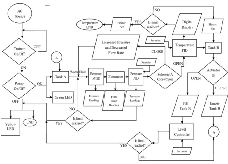
C. Parts and Specification of Trainer
Detailed discussion and specifications of the mentioned components are as follows: Actuators. The actuators will be used to control the water flow.
Electric Solenoids. Two electric solenoids will be installed along the pipes to control the water flow between tanks A and B. This will be automatically switched by the level PID and can also be triggered manually with the use of push buttons.
Faucet. A basic lever manual valve actuator, will be installed on tank A for the purpose of the module’s water drainage for maintenance.
Page | 43 Research Publish Journals
International Journal of Electrical and Electronics Research ISSN 2348-6988 (online) Vol. 8, Issue 2, pp: (42-49), Month: April - June 2020, Available at: www.researchpublish.com
Angle Bar. Two angle bars will be installed as a base for tank B.
Cable Tie and Clamp. Fixtures to keep the cable management neat and proper.
Caster. 2.5-in stem thread swivel with brake casters will be attached on the module base to enable easier moving of the module.
Circuit Breaker. A circuit breaker rated 15 A will be installed in the circuit to protect the trainer module system and its users in case of overloading.
Contactors. A reliable component for the on-off control which will keep the system in a constant state once a button is pushed. Contactor rating will be 220 V.
Heater. A water heater will be installed in tank B.
LCD. A 16x2 LCD with IC2 will be installed as the water level indicator.
LED. LED indicator lights will be installed as an indicator if the module is energized, if the pump is running, if the heater is energized, and a status indicator for the two solenoids.
Yellow LED. Will light up once the module is turned on but with an idle pump.
Green LED. Will light up as an indication once the pump button is pressed and the pump starts running, if the heater is on, and if a solenoid is open.
Red LED. Will light up as an indication if a solenoid is closed.
Module Frame and Base. Will be constructed using steel and plywood.
On-Off Control. This will be a simple part in the system composed of start and stop buttons, contactor, and a coil to serve as the main control of the energizing of the trainer. Another on-off control will be provided for energization and deenergization of the water pump installed in the trainer.
PID Controller. The PID controller will read the sensor then compute the desired actuator output while achieving precision and minimizing error in the instrumentation and control trainer.
Temperature PID Controller. Measures and controls the water temperature in Tank B.
Pressure PID Controller. Measures and limits the pressure in the pipes.
Pipe Clamp. Fixtures to be attached to the module frame and base to hold the pipes in place.
Push Buttons. Will be installed to serve as switches for the on-off control of the laboratory trainer and its installed pump, heater, and solenoids.
Green Push Button. One will serve as an on switch to turn on all the devices in the module once energized
Green Push Button with Lock. Two green push buttons will stand as an on switch for the water pump and heater each, while another two will trigger solenoid A to close and solenoid B to open.
Red Push Button. It will cease all operation and turn the entire module off.
Emergency Stop Button. An emergency stop button will be installed for added precaution.
PVC Pipe. ½-in Clear PVC pipes will be used for the cycling of the water throughout the module.
Relay Module. Will enable the level sensor to control the solenoids and pump
Rotary Encoder. Will be installed and connected to the ultrasonic level sensor for water level adjustment. This will stand as the prototype’s level controller.
Sensor. Flow and pressure sensors are to be installed along the pipes of the module to measure the water cycling in the system and display its parameters.
Flowmeter. A flowmeter will be installed in the lower level of the pipe next to the pressure gauge.
Pressure Gauge. A 10 bar pressure gauge will be installed in the lower level of the pipe.
Page | 44 Research Publish Journals
International Journal of Electrical and Electronics Research ISSN 2348-6988 (online) Vol. 8, Issue 2, pp: (42-49), Month: April - June 2020, Available at: www.researchpublish.com
Transducer. The prototype is designed to consist of temperature, level, and pressure transducers which detects respective parameters then sends the signals to their respective PIDs.
Thermocouple. The temperature transducer to be used in the system, measures the temperature in Tank B then sends the signal to the temperature PID.
Ultrasonic Level Sensor. An Arduino Uno R3 model HC-SCR04 will be programmed and installed into the prototype to act as its level transducer.
Pressure Transmitter. Will stand as the prototype’s pressure transducer, built-in inside the pressure controller.
Water Pump. The water pump will bring the water to flow from one container to another through the PVC pipes. The water pump to be used is rated 220 V, 60Hz, 0.5 HP, with a maximum flow rate of 35 L/min.
Water Tank. Two clear acrylic water tanks with an 6.8-liter capacity will be installed onto the module. It must be transparent for monitoring and observation. (Inner L:W:H = 19 cm:19 cm:19 cm).
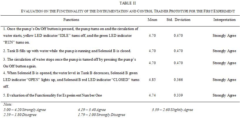
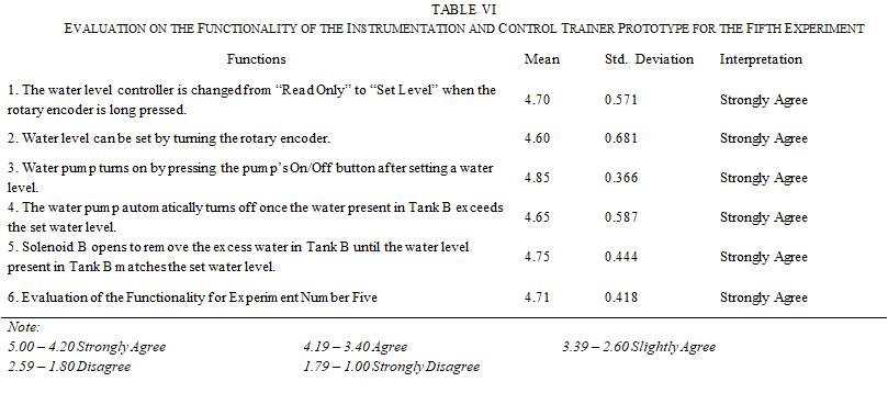
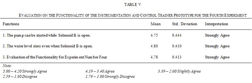
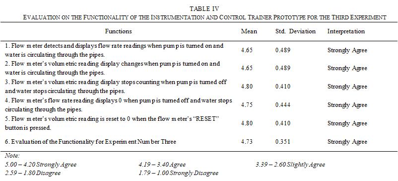
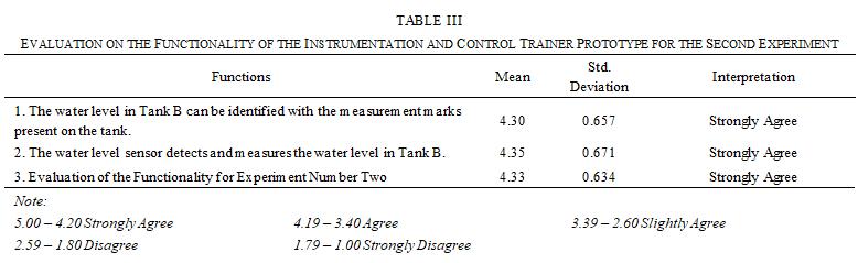
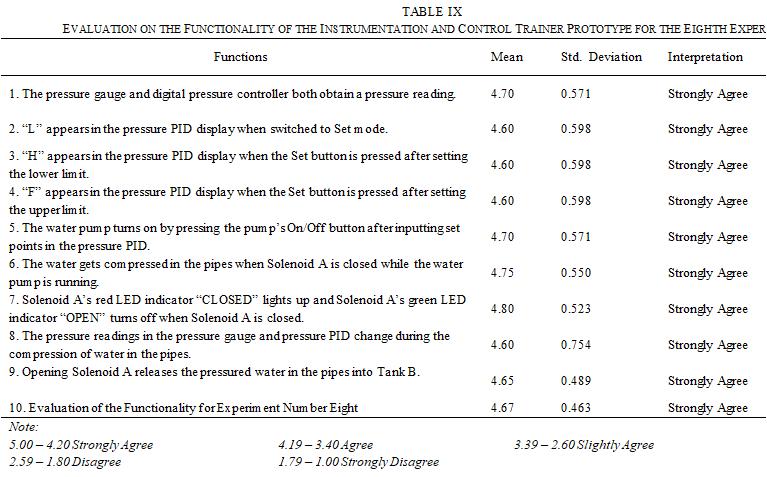
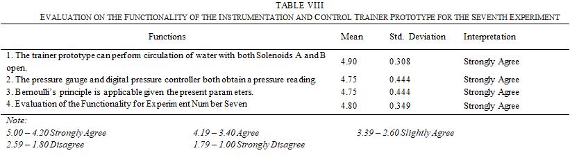
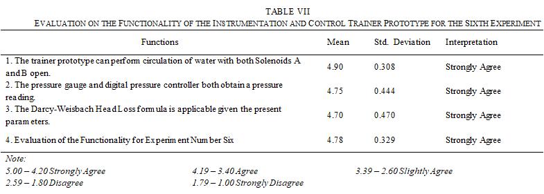
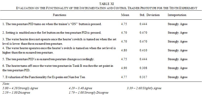
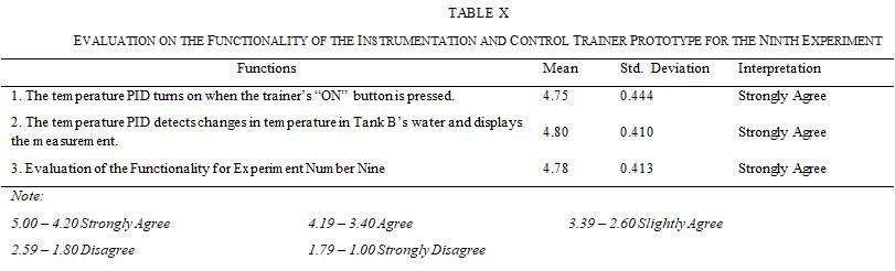
III. RESULTS AND DISCUSSION
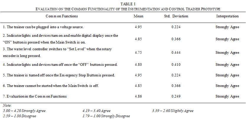
Researchers conducted a survey to validate the functionality and credibility of the device. In the said survey the participants are composed of student and faculty member of the university. The results are as follows:
Page | 45 Research Publish Journals
International Journal of Electrical and Electronics Research ISSN 2348-6988 (online) Vol. 8, Issue 2, pp: (42-49), Month: April - June 2020, Available at: www.researchpublish.com
Page | 46 Research Publish Journals
International Journal of Electrical and Electronics Research ISSN 2348-6988 (online) Vol. 8, Issue 2, pp: (42-49), Month: April - June 2020, Available at: www.researchpublish.com
Page | 47 Research Publish Journals
International Journal of Electrical and Electronics Research ISSN 2348-6988 (online) Vol. 8, Issue 2, pp: (42-49), Month: April - June 2020, Available at: www.researchpublish.com
IV. CONCLUSION
This study was conducted to develop an instrumentation and control laboratory trainer that can measure and control various parameters with sensors, transducers, actuators, on-off, and PID controllers integrated in a single system, to aid engineering students and faculty regarding the course and with the help of a simple interface and operation compared to training modules fabricated by larger companies.
To achieve the objectives of the study, the proponents have conducted various researches with regards to every main component of the planned module. The prototype design was planned as shown in the flowcharts and was succeeded by the gathering of materials and components. After assembly, the prototype was tested for accuracy and functionality.
The instrumentation and control laboratory trainer was designed with a simple interface that can accurately measure the pressure, flow rate, temperature and water level together with the control of actuators with a successful manual and automatic switching. It is an integrated single-system laboratory trainer with flow and pressure sensors, temperature, pressure, and level transducers, actuators, on-off control, and PID controllers.
Page | 48 Research Publish Journals
International Journal of Electrical and Electronics Research ISSN 2348-6988 (online) Vol. 8, Issue 2, pp: (42-49), Month: April - June 2020, Available at: www.researchpublish.com
ACKNOWLEDGMENT
The researchers wish to show their gratitude and appreciation to their research adviser, Engr. Dave T. Alviz, who greatly helped and offered support and guidance. Deepest gratitude is also due to the panel members of examiners, Engr, Oligario T. Suaiso, Engr. Delia Myrna S. Fainsan, Engr. John Christopher V. Yacap, and Engr. Leah Q. Santos, without their knowledge and assistance, the study would not have been a success.
Special thanks to Mr. David L. Prodigalidad for the abundant support and efforts in assisting the researchers on the construction of the prototype.
The researchers are also extremely grateful to their beloved families, who have provided their undying support.
And last but not the least, many thanks to God, for giving the researchers the guidance and wisdom which helped them learn and complete the project.
REFERENCES
[1] Bishop, O. (2011). Electronics circuits and systems. United Kingdom, Taylor & Francis.
[2] Iyengar, Parameshwaran, Phoha, Balakrishnan & Okoye(2011). Fundamentals of Sensor Network Programming. New Jersey, John Wiley and Sonc Inc.
[3] Transducers. Retrieved from http://www.engr.usask.ca/classes/EE/323/notes_2005/chapter7.pdf
[4] Actuator and its different types (2017). Retrieved from https://www. mechlectures. com/actuator-and-its-types/
[5] PID theory explained (2019). Retrieved from https://www. ni. com/en-ph/innovations/white-papers/06/pid-theoryexplained. Html
BIOGRAPHY:
Ysabelle Louiseanne R. Cruto was born on May 11, 1996 in Quezon City. She is currently a BS Electrical Engineering student at Lyceum of the Philippines University at Manggahan, General Trias City, Cavite. She finished her internship at Merlaco Ecozone Power located in Cavite Economic Zone Dr, Rosario, Cavite.

Iverson P. Sasis, was born on September 17, 1999 at General Trias City, Cavite. He is currently a BS Electrical Engineering student at Lyceum of the Philippines University at Manggahan, General Trias City, Cavite. He finished his internship at Merlaco Ecozone Power located in Cavite Economic Zone Dr, Rosario, Cavite.

Page | 49 Research Publish Journals