
Vol. 8, Issue 3, pp: (19-28), Month: July - September 2020, Available at: www.researchpublish.com
Strengthening of Circular Reinforced Concrete Columns with Steel FiberAdded to the Mix after Fire Exposure
1
Nasr Z. Hassan , Mostafa A. Osman2 , Doaa Y. Mohammed31Associate Professor, Civil Eng. Dept., Helwan University, Cairo, Egypt
2Associate Professor, Civil Eng. Dept., Helwan University, Cairo, Egypt
3Teaching Assistance, Civil Eng. Dept., Helwan University, Cairo, Egypt
Abstract: Columns are considered one of the most important structural elements in buildings; they transfer the load directly to the foundations. thus, their exposure to any variables or any extreme conditions such as fire may cause the collapse of the building as a result of buckling of columns.
The main objectives of this research are to investigate the effect of using the steel fiber reinforcing polymer on the strengthening of circular R.C Columns after exposure to fire. In the experimental program, the volume fraction of steel fiber, strengthening FRP area and method of Strengthening using FRP on the specimens varied in order to determine the effect of these variables on the specimen strength and axial displacement.
The experimental program consists of ten reinforced concrete short columns. A column was tested as a control column without steel fiber and without fire, nine columns with different percentages of steel fiber in the mix (0, 0.5%, 1.0%, and 1.5%) by weight, three specimens of the nine were tested only without fire, and six specimens were exposed to fire. then the columns were strengthened with glass fiber with strip of width (100mm, 200mm) respectively.
Experimental results indicated that adding steel fiber by different volume fractions increased the load carrying capacity of the reinforced concrete columns.
Keywords: FRP, axial displacement, steel fiber.
I. INTRODUCTION
The proposed technique of using steel fiber reinforced concrete reduces the manufacture and labor cost that is typically associated with conventional methods. Steel fiber reinforced concrete (SFRC) is used to reduce the problems occurring in concrete such as the weakness of concrete strength at the tension zone.
Strengthening of concrete structural members like Columns may be required on many cases such as Deterioration of structure due to environmental effect damage caused by accidents, upgrading loading requirements, revision in loading standards, and seismic retrofitting.
This research also includes a study of the effect of each variable on crack patterns, failure shape, load - deformation curves, steel strains, the stiffness, the ductility and energy absorption. From all these parameters a suggestion can be made to strengthen reinforced concrete columns after being exposed to fire.
II. EXPERIMENTAL PROGRAM
The experimental study herein tested ten reinforced concrete columns divided into four groups O, A, B and C. all specimens have same dimensions cross section, the cross section is circular section with dimensions 200 mm Diameter and 1250 mm Height. All columns have constant reinforcement. The longitudinal reinforced was 6Ф12 (grade 36/52) and 5Ø8 / m’ was used (grade 24/35) as separate stirrups in transverse direction show in Figure (1).
International Journal of Engineering Research and Reviews ISSN 2348-697X (Online)
Page | 19 Research Publish Journals
International Journal of Engineering Research and Reviews ISSN 2348-697X (Online) Vol. 8, Issue 3, pp: (19-28), Month: July - September 2020, Available at: www.researchpublish.com
Ten specimens are divided into four groups, the first group (GO) consisted only of column was cast without steel fibers and was examined under no fire conditions. The second group (GA) consisted of 3 columns with steel fiber (Vf)=0.5%, the two columns are exposed to fire for 2 hours at 600°c, and cooled in the open air then strengthened with glass fiber. The third group (GB) consisted of 3 columns with steel fiber (Vf)=1%, the two columns were exposed to fire for 2 hours at 600°c, and cooled by air then strengthened with glass fiber. The fourth group (GC) consisted of 3 columns with steel fiber ( Vf)=1.5%, the two columns were exposed to fire for 2 hours at 600°c, and cooled by air then strengthened with glass fiber. The width of the used strips in the columns was 20cm and 10cm; the distance between the strips is 10cm.
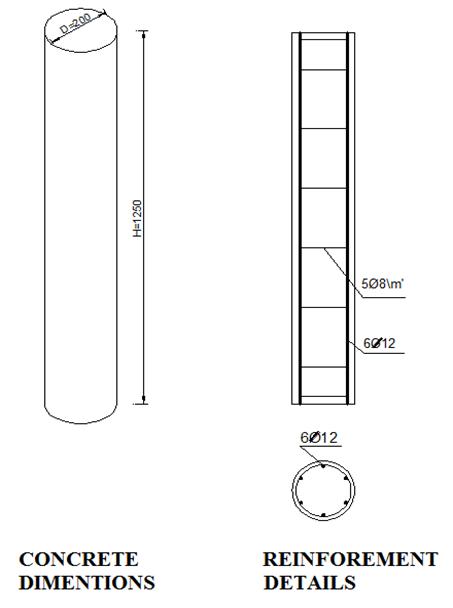
Figure (1): Details of Typical Specimen.
III. MATERIAL CHARACTERISTICS
The materials used to cast the specimens were made from locally available materials (sand, dolomite, ordinary Portland cement and drinking water). A mix was designed to reach target cubic compressive strength of 250 kg/m2 after 28 days. High tensile ribbed steel bars of 12 mm diameter and yield stress of 360MPa were used as main steel of columns. Mild smooth steel 8 mm diameter and 240MPa were used as stirrups in all columns. Tests were carried out according to the Egyptian Standard Specification No. 262 / 2000. The used steel fiber with length 50 mm, diameter 0.5 mm, aspect ratio 100, density 78.5 KN/m3, an ultimate tensile strength of 1100 MPa, and an ultimate tensile strain of 2.2% (based on the manufacturer). The average characteristic concrete strength of tested cubes was 32.7 MPa, 25.8 MPa, 25.9 MPa and 28.5 MPa respectively relative to specimens of steel fiber volume fraction of 0.0%, 0.5%, 1.0 % and 1.5%.The use glass fiber with Dry fiber density 1.85 g\cm2 , dry fiber tensile strength 1.170 N\mm2 , dry fiber modulus of elasticity in tension 76 N\mm2 , cross section 95 mm2 , is show in Figure (2) and Figure (3).
Figure (2): Steel Fiber.
Figure (3): Glass Fiber.

Page | 20 Research Publish Journals
International Journal of Engineering Research and Reviews ISSN 2348-697X (Online) Vol. 8, Issue 3, pp: (19-28), Month: July - September 2020, Available at: www.researchpublish.com
IV. SPECIMEN-PREPARATION
Test specimens were cast into PVC Smooth plastic pipes. All test specimens were casted in the same day and after 24 hours remove plastic pipes (PVC) for all columns and cured them with using water. A special fire furnace was designed for the purposes of fire. Six columns were strengthened by Glass Fiber after being exposed to the fire.
To measure strain used electrical strain gauges location in the mid height of the reinforcement steel column and used axial displacement and horizontal displacements were measured using LVDTs to accuracy of 0.01 mm, the horizontal displacement location at the mid height and the other at ¼ the height .
V. ANALYSIS AND DISCUSSION
Table (1) illustrates the outcomes of the experiments for all tested specimens as the maximum loads, the cracking loads. For all tested specimens, by adding volume fraction of Steel fiber to the columns, the ultimate load increased compared to control specimen.
Table (1): Test Results.
Specimens % volume fraction PCr (kN) Pfailue (kN)
Mode of Failure
Pfailure./ Pfailure. control (CO)
Pfailure / Pfailure control (C1A,C1B, & C1C)

Max. Displacement (mm)
CO 0 227 702.3 Crushing 1 4
C1A 0.50 249 723.3 Crushing 1.029 1 3.63
C1B 1.00 280 734.1 Crushing 1.045 1 3.5
C1C 1.50 350 943.4 Crushing 1.330 1 4
C2A 0.50 216 606.7 Crushing 0.863 0.838 3.66
C2B 1.00 246 709.8 Crushing 1.010 0.966 3.63
C2C 1.50 274 914.6 Crushing 1.302 0.969 5.21 C3A 0.50 275 744.7 Crushing 1.060 1.029 4.35 C3B 1.00 295 750.8 Crushing 1.069 1.022 3.70 C3C 1.50 300 920.6 Crushing 1.310 0.975 5.76
VI. A COMPARISON BETWEEN THE COLUMNS WITH DIFFERENT STEEL FIBER CONTENT LOAD- DISPLACEMENT CURVES
Figure (4) show the relationship between the applied load and axial displacement. It is found that column (C1B) which has a volume fraction (Vf) of steel fiber equal to 1.00% is the most effective percentage in controlling the axial displacement. The results for columns (C1A), (C1B) with (CO), it was found that the measure of ductility increased by 15% and 27.5% respectively for both columns.
800
200
0
1000 0 1 2 3 4 5 Axial Displacement(mm)
Figure (4): Load-Axial Displacement Relationship.
CO C1A CIB C1c
Page | 21 Research Publish Journals
International Journal of Engineering Research and Reviews ISSN 2348-697X (Online) Vol. 8, Issue 3, pp: (19-28), Month: July - September 2020, Available at: www.researchpublish.com
Figure (5) show the relationship between the applied load and axial displacement for three columns (C2A, C2B and C2C) which has a volume fraction (Vf) = (0.5%, 1.0%, 1.5%) and exposed to fire (at elevated temperature) for 2hours at 600°c and then strengthened with Glass fiber strips. Figure (6) show the relationship between the applied load and axial displacement for three columns (C3A, C3B and C3C) which has a volume fraction (Vf) = (0.5%, 1.0%, 1.5%) and exposed to fire (at elevated temperature) for 2hours at 600°c and then strengthened with Glass fiber strips.
The higher volume fraction of Steel fiber the recorded axial displacement was higher than in columns. The reason may be due to the effect of the fire exposure on the bond between steel fibers and the surrounding concrete which will act as confinement to the concrete. However, for column (C3B), the steel fiber was able enhance the axial displacement. Hence by increasing the volume fraction (Vf) of Steel fiber.
800
200
0
1000 0 1 2 3 4 5 6
Displacement(mm)
Displacement
Figure (5): Load-Axial Displacement. Figure (6): Load-Axial Displacement.


VII. STIFFNESS AND DUCTILITY
Figure (7) and Figure (8) show the results Stiffness and ductility. This is obvious especially for the column (C1C) which has a volume fraction (Vf) = 1.5%, which is more stiffener than the other columns, it recorded an increase in the stiffness by 10.1%.
Figure (7): Stiffness.
Figure (8): Measure of Ductility.
Figure (9) and Figure (10) show that the stiffness of the columns decreased after exposure to fire; meanwhile strengthening the columns with Glass fiber strips did not have a significant effect on column load stiffness, the columns became more ductile after being exposed to fire.
Page | 22 Research Publish Journals
Axial
C2A C2B C2c 0 200 800 1000 0 1 2 3 4 5 6
0 200
832.4 CO C1A C1B C1C 0 0.5
2.05 C0 C1A C1B C1C
Axial
C3A C3B C3c
800 1000
2.5 3
International Journal of Engineering Research and Reviews ISSN 2348-697X (Online)
Vol. 8, Issue 3, pp: (19-28), Month: July - September 2020, Available at: www.researchpublish.com
Figure (9): Stiffness.
Figure (10): Measure of Ductility.
Figure (11) and Figure (12) show that in case of fire and strengthening with Glass fiber strips of width 200mm, the results showed that the stiffness of the columns increased with increasing the volume fraction of Steel fiber used That is why (C3C) which has volume fraction of Steel fiber equal to 1.50% is stiffer than the other columns. By comparing between the ductility values of columns (C3B) and (C3C), the recorded results showed an increase in ductility by ...4%.
Figure (11): Stiffness.
Figure (12): Measure of Ductility.
VIII. A COMPARISON BETWEEN THE COLUMN EFFECT OF FIRE AND STRENGTHENING LOAD- DISPLACEMENT CURVES
In general, it is noticed that the fire has a bad effect on axial displacement values which were relatively high; in addition, the strengthening with Glass fiber did not control the axial displacement. Show in the Figure (15) after being exposed to fire, the axial displacement of column (C2C) recorded an increase by 21.5% compared of the column (C1C) and The comparison between (C2C) and (C3C) recorded an increase in the value of axial displacement by 9.5%.
Figure (13): Load-Axial Displacement.


Figure (14): Load-Axial Displacement.

Page | 23 Research Publish Journals
0 200 800 1000 321.7 C2A C2B C2C 0 0.5 2.5 3 1.7 C2A C2B C2c 0 200 800 1000 836.9 C3A C3B C3C 0 0.5 3 3.5 2.9 C3A C3B C3C 0 200 800 1000 0 1 2 3 4 5 Axial Displacement(mm) C1A C2A C3A 0 200 800 1000 0 1 2 3 4 Axial Displacement C1B C2B C3B
International Journal of Engineering Research and Reviews ISSN 2348-697X (Online)
Vol. 8, Issue 3, pp: (19-28), Month: July - September 2020, Available at: www.researchpublish.com
800
200
0
1000 0 1 2 3 4 5 6
Axial Displacement (mm)


Figure (15): Load-Axial Displacement Relationship.
IX. STIFFNESS AND DUCTILITY
Figure (16) and Figure (17) show the results Stiffness and ductility, It can be seen that the strengthening with a strip of width 100mm or 200mm did not affect the ductility and stiffness of columns in this group; at variance the column (C3A) which exposed to fire and strengthened with a strip of width 200mm, is stiffer than the other columns at the same time it has the least column ductility.
Figure (16): Stiffness.
Figure (17): Measure of Ductility. According to figure (18,19,20 and 21), It is found that the fire has an observed bad effect on the stiffness of the columns this was significant especially in case of strengthening with Glass fiber strip with 100mm width The column was not exposed to fire is the least column in ductility.
Figure (18): Stiffness.
Figure (19): Measure of Ductility.
Page | 24 Research Publish Journals
C1B
C1C C2C C3c 0 200 800 1000 493.2 C1A C2A C3A 0 0.5 3 1.7 C1A C2A C3A 0 1000 734
C2B C3B 0 0.5 3 1.8 C1B C2B C3B
Figure (20): Stiffness.
Figure (21): Measure of Ductility.
X. VARIATIONS WITH CODES MODELS


Used Model (1) show Euro code 2, ENV BC2 Design of concrete structures, General Rules and Rules of Buildings, DD. ENV, 1995[1], Model (2) show International workshop “Fire Design of concrete structures” University of Coinbra, Portugal, November 2007[2] , Model (3) show Effect of Fire Damage on the structural properties of steel elements, April 30, 2011 University of Pittsburgh, according to ASTM - A514 [3] and used Model Equation From the ACI 318 section 7.10.5 [4] , the result are show in Figure (22) and Figure (23).
Page | 25 Research Publish Journals
International Journal of Engineering Research and Reviews ISSN 2348-697X (Online) Vol. 8, Issue 3, pp: (19-28), Month: July - September 2020, Available at: www.researchpublish.com
Experimental Loads Versus Used [0.0%, 0.5%, 1.0%and 1.5%] Model Loads [4].
Experimental Loads Versus Used [0.5%, 1.0%and 1.5%] Model Loads [1], [2], [3], [4]. 0 200 800 1000 832.3 C1C C2C C3C 0 0.5 2.5 3 2.01 C1C C2C C3C 0 100 200 300 700 800 900 1000 CO C1A C1B C1C Experimental loads 0 100 200 300 400 700 800 900 1000 C2A C2B C2C C3A C3B C3C Experimental loads Model 1 Model2
Figure (22):
Figure (23):
International Journal of Engineering Research and Reviews ISSN 2348-697X (Online) Vol. 8, Issue 3, pp: (19-28), Month: July - September 2020, Available at: www.researchpublish.com
Variation with reference (Hanna Suliman Al-Nimry and Aseel Mohammad Ghanem) Results [5].
All column specimens were designed as short columns with a circular cross section of 192 mm diameter and an unsupported length of 900 mm. six steel deformed rebars of 10-mm diameter and Transverse reinforcement was provided using 6-mm diameter deformed ties at a uniform spacing of 150 mm. The ties were provided at 60 mm.
Table (2): Test Specimens [4].
Specimen designation Fire condition Strengthening condition Fu(KN) Control CH0-A No Fire 989.1
CH2-G1L Fire (2 hours) wrapped with1 layer of GFRP 790.5 CH2-G2L Fire (2 hours) wrapped with 2 layer of GFRP 1045.3
Table (3): Response Parameters for Test Specimens.
Specimen designation Fire condition Volume Fraction(Vf)% Strengthening condition Fu(KN)


Control C1A No Fire 0.5% 723.3 C2A Fire (2 hours) 0.5% wrapped with Strip of GFRP 100mm 606.7 C3A Fire (2 hours) 0.5% wrapped with Strip of GFRP200mm 744.7
The residual strength of the tested specimens in our research are rather high compared to the residual strength of the specimens experimented by Hanan Suliman [4]; this may be due to the difference in the used concrete mix, in our research the specimens contained steel fiber in their concrete mix where in the reference the specimens did not contain any steel fibers. This means that the steel fiber used in the concrete mix has a positive effect on the strength and capacity of columns.
Page | 26 Research
Publish Journals
Reduction Ration 20%. Reduction Ration 13.7%. Residual Ration 80%. Residual Ration
86.3%.
0 200 400 1000 1200 Control
790.5
0 200 400 1000 1200 C1A C2A 703.3
CH0-A CH2-G1L
Hanna Sulima…
Experiment al load
Vol. 8, Issue 3, pp: (19-28), Month: July - September 2020, Available at: www.researchpublish.com
Increased Ration 5.7%
Increased Ration 5.9%
By variation between both ration we will notice that they were approximately the same, this may be interpreted that the used steel fiber in our experimental program together with using GFRP gave the same result as that was given by the program used in the reference. They used full strengthening with GFRP.
XI. CONCLUSIONS
1- By increasing the steel fiber volume fraction, the number of cracks and their width decrease this may be due to the action of the closely spaced fibers and the concrete paste.
2- Adding steel fiber to the mixture by different volume fractions 0.5%, 1% and 1.50%) increased the load carrying capacity of the reinforced concrete columns by (2.8%, 4.2% and 25.5%) respectively compared to the control column without fiber.
3- Adding steel fiber to the concrete affected the stiffness of the concrete columns, as the volume fraction of steel fiber increased by (0.5%, 1% and 1.50%) the stiffness increased by 15.7%, 44.4% and 50% respectively.
4- By subjecting the columns to high temperature, a general deterioration was obvious in their properties; this appeared as a loss in the compressive strength, cracking and spalling of concrete, destruction in the bond between the cement paste and the aggregates and finally crushing and splitting of the concrete parts.
5- For strengthening of specimens with strips of fiber glass the failure load increased with increased the width of the strip from 100mm to 200mm, the failure load also varied with the variance of the steel fiber volume fraction.
XII. VARIATIONS WITH CODES MODELS
1. The tested specimens (CO, C1A, C1B, and C1C) which contained a volume fraction of steel fiber (0%) are considered the control specimens; those specimens complied with the ACI equation.

2. The models were rather conservative especially in dealing with the case of fire; hence the used reduction factors caused a reduction in the loads which is high relative to the actual experimental results.
3. In the model equations there is not a term that considers the volume fraction of steel fiber that was added to the tested specimens.
4. The experimental result of the control column (CO) which has (Vf) equal 0.0% with no fire and without strengthening, is in good agreement with the ACI equation by average (0.95%).
5. Due to fire and strengthening with GFRP strips of width 100mm, the capacities of columns (C2A, C2B, C2C) with (Vf) equals (0.5%, 1.0% and 1.5%) respectively the compressive strength decreased compared to the control columns with the same volume fraction. However, still those results are more than the models results by average (2.51 %), due to added steel fiber ratio.
International Journal of Engineering Research and Reviews ISSN 2348-697X (Online)
Page | 27 Research Publish Journals
744.7
0 200 400 1000 1200 Control CH0-A CH2-G2L 1045.3 Hanna Suliman [4] 0 200 400 800 1000 1200 C1A C3A
Experimental Load
International Journal of Engineering Research and Reviews ISSN 2348-697X (Online) Vol. 8, Issue 3, pp: (19-28), Month: July - September 2020, Available at: www.researchpublish.com
6. In the case fire and strengthening with GFRP strips of Width 200mm, the capacities of columns (C3A, C3B, C3C) with (Vf) equals (0.5%, 1.0% and 1.5%) respectively the compressive strength increased, compared to the control columns with the same volume fraction. However, still those results are more than the models results by average (4.1%), may be due both the added steel fiber and the strengthening.
REFERENCES
[1] Euro code 2, ENV BC2 Design of concrete structures, General Rules and Rules of Buildings, DD. ENV, 1995.
[2] International workshop (2007): “Fire Design of concrete structures” University of Coinbra, Portugal, November.
[3] Effect of Fire Damage on the structural properties of steel elements, April 30, (2011) University of pittsburgh, according to ASTM - A 514.
[4] CEN. Eurocode 2 (1995): design of concrete structures, Part 1-2: structural fire design. Final draft, pr ENV 1992-12, European Committee for Standardization, Brussels.
Page | 28 Research Publish Journals